1
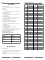
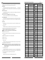
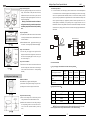
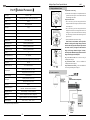
INTELLIGENT SPEED DOME
USER’S MANUAL
Please read the manual in detail before using the product!
Please obey all the rules of operation!
Speed Dome of Security & Safety of IP System
Contents
Part1.Notice
...................................................................4
Part2.Product.&
Part3.Function
Features...............................................4
Description........................................5
Part4.Installation
Preparation.....................................7
Part5.Installation Guidance....................................................7
1.Dome-Insert.Installation
.............................................................................
2.Ceiling—mounted.Installation.........................................................................8
3.Wall-hung.Installation...................................................................
4.Pillar.Installation.of.Dome......................................................................................
5.Lifting.Installation.of.Dome......................................................................................
6.Product.Connection.....................................................................................................
Part.6.
Menu
Setting
of
OSD
7
9
10
11
11
System............................12
1.English
Menu
Index.........................................................................................
12
2.Basic
Operation........................................................................................
13
3.Power-on and Self-check.......................................................................................... 13
4.Main Menu Description............................................................................................. 13
5.System
Information
Setting....................................................................................13
6.Selecting
Camera..................................................................................
14
7.Lens
Parameter
Setting........................................................................................
14
8.Preset
Position
Setting.......................................................................................
14
9.Tour Setting of Preset Position………………………….................................……….. 15
10.Display
Setting...................................................................................................
16
11.Advanced
Settings.......................................................................................
16
12.Home
Position
Setting……...........................................................................
16
13.Outo
Limit
Scan.......................................................................................16
14.Auto
Over-turn.......................................................................................
17
15.Zone
Indication
Setup..............................................................................
17
16.Privacy
Masking
Setting................................................................................
18
17.Tracking Routes Recorder............................................................................................ 19
18.Alarm Setting............................................................................................................... 20
19.Dome
Setting........................................................................................................... 20
Solemn Declaration
While writing this manual, we’ve been very cautious and prudent in
order to guarantee the credibility of all the information provided here. However, if there exists any error, your precious advice and correction will be
greatly appreciated. Meanwhile, the misinterpretation of this manual is not
controllable, so we are not responsible for the accidents and the damage
caused by misunderstanding this manual, the damage to the third party and
thereby the compensation claimed by the third party and the deletion and
loss of information and thereby other indirect loss caused by incorrect software operation, maintenance or other accidental situations.
The distribution and marketing must be conducted by the original
purchaser under the items of permission agreement. No company or individual is allowed to copy or duplicate the whole or part of this product, or convert it into other electronic media readable by other machines.
Any modification of the manual is not likely to be otherwise stated.
Please base on the software when any mismatch for this manual
caused by software upgrading occurs.
Please read the user’s manual carefully before using the product.
Make sure that your operation is complied with the operation procedure.
Part.7.Non-menu.Operation Instruction.........................22
1.Up/down and left/right Movement Control……......................…………..………………….22
2.Auto.Scan....................................................................................................
22
3.Preset.Position.Setting................................................................................................22
4.Call
Preset
Position....................................................................................................22
5.Program
Tour
Group..........................................................................................22
6.Call
Tour
Group.......................................................................................23
7.Home
Position
Setting................................................................................
23
8.Left/right
Limit
Scan
Setting................................................................
23
9.Restore
factory
default.............................................................................23
Part.8.Common functions operating Express .............24
Part.9.Technical.Parameter................................
26
Part.10.Simple.Trouble.Shooting................................27
Part.11.Common.Knowledge.on.RS485.Bus...…...........28
1.Basic.Features.of.RS485.Bus...............................................................................28
2.RS485 control bus transmitting distance........................................................................ 28
3.Connection.Methods.&.Terminal.Resistance......................................................
28
4.Problems.in.Practical.Use...........................................................................29
5.Wires.Recommended...........................................................................................
29
Part.12.code Switch setting table …........................…..30
Intelligent Speed Dome Operation Manual
Part 1 NOTICE
1.Handle with care while transportation.
Do not abuse the camera. Avoid pressing striking, shaking, etc. The camera could be damaged by improper
handling or storage.
2.How to deal with malfunction
If smoke or unusual smell comes out or malfunction occurs, SHUT DOWN the power, STOP using the
camera. Ask a qualified service person for servicing.
3. Do not attempt to disassemble the camera.
To prevent electric shock, do not remove screws or covers. There are no user serviceable parts inside. Ask
a qualified service person for servicing.
4. Do Not put other objects into the camera
No metals or combustible materials inside. If water or other liquid floats in, SHUT DOWN the power
immediately, and ask a qualified service person for servicing. Avoid raindrops and sea water.
5. Handle the camera with care while placing it
Do Not drop the camera or strike or shake it in 8. to avoid the unnecessary damage.
6. Install the camera where it’s away from power source and magnetic fields.
Jamming pictures will be caused if the camera is installed near TV, radio, magnetic device, motor, transformer and loud-speaker, etc.
7. Avoid moisture, dust and high temperature
Do Not install the camera near smoke, steam, or dusty and over-heated places.
8. Do not use strong or abrasive detergents
when cleaning the camera body. Use a dry cloth to clean the camera when dirty. In case the dirt is hard to
remove, use a mild detergent and wipe gently. Care should be taken not to scratch the dome when wiping it.
9. Never face the camera towards the sun, or it may damage the CCD.
10. Operate the camera under the required conditions
※ Warning: Do Not install the indoor speed dome outdoors.
ver2.0
Address
Code
Address Switch
12345678
Address
Code
Address Switch
12345678
195
1 1 0 0 0 0 1 1
226
0 1 0 0 0 1 1 1
196
0 0 1 0 0 0 1 1
227
1 1 0 0 0 1 1 1
197
1 0 1 0 0 0 1 1
228
0 0 1 0 0 1 1 1
198
0 1 1 0 0 0 1 1
229
1 0 1 0 0 1 1 1
199
1 1 1 0 0 0 1 1
230
0 1 1 0 0 1 1 1
200
0 0 0 1 0 0 1 1
231
1 1 1 0 0 1 1 1
201
1 0 0 1 0 0 1 1
232
0 0 0 1 0 1 1 1
202
0 1 0 1 0 0 1 1
233
1 0 0 1 0 1 1 1
203
1 1 0 1 0 0 1 1
234
0 1 0 1 0 1 1 1
204
0 0 1 1 0 0 1 1
235
1 1 0 1 0 1 1 1
205
1 0 1 1 0 0 1 1
236
0 0 1 1 0 1 1 1
206
0 1 1 1 0 0 1 1
237
1 0 1 1 0 1 1 1
207
1 1 1 1 0 0 1 1
238
0 1 1 1 0 1 1 1
208
0 0 0 0 1 0 1 1
239
1 1 1 1 0 1 1 1
209
1 0 0 0 1 0 1 1
240
0 0 0 0 1 1 1 1
210
0 1 0 0 1 0 1 1
241
1 0 0 0 1 1 1 1
211
1 1 0 0 1 0 1 1
242
0 1 0 0 1 1 1 1
212
0 0 1 0 1 0 1 1
243
1 1 0 0 1 1 1 1
213
1 0 1 0 1 0 1 1
244
0 0 1 0 1 1 1 1
214
0 1 1 0 1 0 1 1
245
1 0 1 0 1 1 1 1
Indoor speed dome
Outdoor speed dome
215
1 1 1 0 1 0 1 1
246
0 1 1 0 1 1 1 1
Temperature: -10~ 50°C
Temperature: -40~55°C
216
0 0 0 1 1 0 1 1
247
1 1 1 0 1 1 1 1
Humidity:<90%
Humidity:<90%
217
1 0 0 1 1 0 1 1
248
0 0 0 1 1 1 1 1
218
0 1 0 1 1 0 1 1
249
1 0 0 1 1 1 1 1
219
1 1 0 1 1 0 1 1
250
0 1 0 1 1 1 1 1
220
0 0 1 1 1 0 1 1
251
1 1 0 1 1 1 1 1
221
1 0 1 1 1 0 1 1
252
0 0 1 1 1 1 1 1
222
0 1 1 1 1 0 1 1
253
1 0 1 1 1 1 1 1
223
1 1 1 1 1 0 1 1
254
0 1 1 1 1 1 1 1
224
0 0 0 0 0 1 1 1
255
1 1 1 1 1 1 1 1
225
1 0 0 0 0 1 1 1
KPA::86-106kpa
KPA::86-106kpa
AC: 24v/1.5A 50/60Hz
AC : 24v/3.0A 50/60Hz
Part 2 Product features
1.Auto-recognition zoom camera
Our Intelligent speed dome is auto-recognizable for SONY, HITACHI, SANYO, SAMSUNG, LG, CNB,
CANON etc. and some domestic zoom cameras. (Other zoom cameras should provide their protocols)
2.Built-in Decoder/PAN/TILT
◆
Adopt the ARM design of high performance with high, stable stability. Setting data will not be lost when
power-off.
◆
4
33
Intelligent Speed Dome Operation Manual
◆
Address Code
Address Switch
12345678
Address
Code
Address Switch
12345678
123
1 1 0 1 1 1 1 0
159
1 1 1 1 1 0 0 1
◆
124
0 0 1 1 1 1 1 0
160
0 0 0 0 0 1 0 1
◆
125
1 0 1 1 1 1 1 0
161
1 0 0 0 0 1 0 1
◆
126
0 1 1 1 1 1 1 0
162
0 1 0 0 0 1 0 1
127
1 1 1 1 1 1 1 0
163
1 1 0 0 0 1 0 1
128
0 0 0 0 0 0 0 1
164
0 0 1 0 0 1 0 1
129
1 0 0 0 0 0 0 1
165
1 0 1 0 0 1 0 1
◆
◆
◆
◆
◆
◆
ver2.0
Precision stepper electrode drive smooth operation, accurate positioning
Infinitely variable speed Continuous 360°pan, tilt turning(180° auto flip), without any blind area.
Automatic identification PELCO-D, PELCO-P Control Protocol
Automatic identification Baud rate 2400,4800,9600
Broadcast address 255 and Invalid address 0, Convenient control
Software address ,Software Baud rate ,Software Protocol function ,Convenient setting
256 preset positions, 5 automatic programmable cruising function which can store 16 presets, including
guarding point, cruising group,
4 tracking record, 8privacy protecting area and 8 area indication, etc.
3 different Optional speed cruising function
RS485 control bus
3.Build-in digital color camera
130
0 1 0 0 0 0 0 1
166
0 1 1 0 0 1 0 1
131
1 1 0 0 0 0 0 1
167
1 1 1 0 0 1 0 1
◆
Integrated digital processing camera with high sensitivity and high resolution.
132
0 0 1 0 0 0 0 1
168
0 0 0 1 0 1 0 1
◆
Auto focus, auto aperture, auto brightness compensation ,auto White Balance.
133
1 0 1 0 0 0 0 1
169
1 0 0 1 0 1 0 1
◆
Auto color/grayscale picture change, auto backlight supplement and auto shutter.
134
0 1 1 0 0 0 0 1
170
0 1 0 1 0 1 0 1
135
1 1 1 0 0 0 0 1
171
1 1 0 1 0 1 0 1
136
0 0 0 1 0 0 0 1
172
0 0 1 1 0 1 0 1
137
1 0 0 1 0 0 0 1
173
1 0 1 1 0 1 0 1
138
0 1 0 1 0 0 0 1
174
0 1 1 1 0 1 0 1
139
1 1 0 1 0 0 0 1
175
1 1 1 1 0 1 0 1
140
0 0 1 1 0 0 0 1
176
0 0 0 0 1 1 0 1
141
1 0 1 1 0 0 0 1
177
1 0 0 0 1 1 0 1
142
0 1 1 1 0 0 0 1
178
0 1 0 0 1 1 0 1
143
1 1 1 1 0 0 0 1
179
1 1 0 0 1 1 0 1
144
0 0 0 0 1 0 0 1
180
0 0 1 0 1 1 0 1
145
1 0 0 0 1 0 0 1
181
1 0 1 0 1 1 0 1
146
0 1 0 0 1 0 0 1
182
0 1 1 0 1 1 0 1
147
1 1 0 0 1 0 0 1
183
1 1 1 0 1 1 0 1
148
0 0 1 0 1 0 0 1
184
0 0 0 1 1 1 0 1
149
1 0 1 0 1 0 0 1
185
1 0 0 1 1 1 0 1
150
0 1 1 0 1 0 0 1
186
0 1 0 1 1 1 0 1
151
1 1 1 0 1 0 0 1
187
1 1 0 1 1 1 0 1
152
0 0 0 1 1 0 0 1
188
0 0 1 1 1 1 0 1
153
1 0 0 1 1 0 0 1
189
1 0 1 1 1 1 0 1
154
0 1 0 1 1 0 0 1
190
0 1 1 1 1 1 0 1
155
1 1 0 1 1 0 0 1
191
1 1 1 1 1 1 0 1
156
0 0 1 1 1 0 0 1
192
0 0 0 0 0 0 1 1
157
1 0 1 1 1 0 0 1
193
1 0 0 0 0 0 1 1
158
0 1 1 1 1 0 0 1
194
0 1 0 0 0 0 1 1
32
Part 3【Function description】
This section only mentions main functions and their operation principles , the detailed operation will
be in other section..
1.Target tracking
Users can control the moving direction of lens by pushing joystick up and down, left and right to trace the
target or change the view-angles. The size of visual angle or target image can be adjusted by changing focus.
2.Focus length/auto matching technology of rotation speed
In the situation where focal length is long, the image will be easily distorted because speed dome responses
so fast that even a slight touch of joystick could make the picture shift rapidly. Based on people-oriented design, this speed dome camera can automatically adjust pan and vertical speed according to the focal length to
make the manual trace operation easier.
3.Auto-rotate
If operator keeps pressing the joystick after reaching the limitation in vertical direction, the lens would
automatically rotate 180°, so we can monitor the hind-scene
4.Set and transfer preset
Preset is a function that we can store parameters like the angle of PAN and the length of focus in the
memory, and the speed dome could adjust itself to reach the angle of PAN and the length of focus when you
transfer the preset.
5. Tour
Automatic tour, which arranges presets in the desired order and interval by programming, is a build-in
function of this intelligent speed dome. With a command, the camera of speed dome would tour automatically
and continuously according to the route and interval preprogrammed.
6.Auto-- scan
The high speed dome camera can automatically and repeatedly scan 360°at both high speed and slow
speed.
7.Limit scan
To set the starting point of limit scan by using the start command in the control keyboard, and then use the
5
Intelligent Speed Dome Operation Manual
joystick to move to the end point of limit scan at a certain speed. After calling the limit scan, camera will automatically scan between the start and end points at the speed of joystick moving.
Address Switch
ver2.0
Address Switch
Address
Code
12345678
Address
Code
12345678
51
1 1 0 0 1 1 0 0
87
1 1 1 0 1 0 1 0
52
0 0 1 0 1 1 0 0
88
0 0 0 1 1 0 1 0
53
1 0 1 0 1 1 0 0
89
1 0 0 1 1 0 1 0
54
0 1 1 0 1 1 0 0
90
0 1 0 1 1 0 1 0
55
1 1 1 0 1 1 0 0
91
1 1 0 1 1 0 1 0
56
0 0 0 1 1 1 0 0
92
0 0 1 1 1 0 1 0
57
1 0 0 1 1 1 0 0
93
1 0 1 1 1 0 1 0
58
0 1 0 1 1 1 0 0
94
0 1 1 1 1 0 1 0
59
1 1 0 1 1 1 0 0
95
1 1 1 1 1 0 1 0
60
0 0 1 1 1 1 0 0
96
0 0 0 0 0 1 1 0
61
1 0 1 1 1 1 0 0
97
1 0 0 0 0 1 1 0
62
0 1 1 1 1 1 0 0
98
0 1 0 0 0 1 1 0
63
1 1 1 1 1 1 0 0
99
1 1 0 0 0 1 1 0
64
0 0 0 0 0 0 1 0
100
0 0 1 0 0 1 1 0
65
1 0 0 0 0 0 1 0
101
1 0 1 0 0 1 1 0
66
0 1 0 0 0 0 1 0
102
0 1 1 0 0 1 1 0
67
1 1 0 0 0 0 1 0
103
1 1 1 0 0 1 1 0
※NOTE: Camera can NOT automatically focus in the following situation:
68
0 0 1 0 0 0 1 0
104
0 0 0 1 0 1 1 0
◆Target is not the center of the screen.
69
1 0 1 0 0 0 1 0
105
1 0 0 1 0 1 1 0
◆Clear picture of target would not be guaranteed when observing them both in the distance and close-up at
70
0 1 1 0 0 0 1 0
106
0 1 0 1 0 1 1 0
71
1 1 1 0 0 0 1 0
107
1 1 0 1 0 1 1 0
◆Target can’t be a strong light object, such as neon light and spotlight
72
0 0 0 1 0 0 1 0
108
0 0 1 1 0 1 1 0
◆Target moves too fast
73
1 0 0 1 0 0 1 0
109
1 0 1 1 0 1 1 0
◆Target is too dark or blur
74
0 1 0 1 0 0 1 0
110
0 1 1 1 0 1 1 0
c、Aperture control:
75
1 1 0 1 0 0 1 0
111
1 1 1 1 0 1 1 0
Auto-IRIS is included in system default. Camera adjusts IRIS according to the change of environmental
light to stabilize images. Auto aperture is advised.
76
0 0 1 1 0 0 1 0
112
0 0 0 0 1 1 1 0
77
1 0 1 1 0 0 1 0
113
1 0 0 0 1 1 1 0
78
0 1 1 1 0 0 1 0
114
0 1 0 0 1 1 1 0
79
1 1 1 1 0 0 1 0
115
1 1 0 0 1 1 1 0
80
0 0 0 0 1 0 1 0
116
0 0 1 0 1 1 1 0
81
1 0 0 0 1 0 1 0
117
1 0 1 0 1 1 1 0
82
0 1 0 0 1 0 1 0
118
0 1 1 0 1 1 1 0
83
1 1 0 0 1 0 1 0
119
1 1 1 0 1 1 1 0
84
0 0 1 0 1 0 1 0
120
0 0 0 1 1 1 1 0
85
1 0 1 0 1 0 1 0
121
1 0 0 1 1 1 1 0
86
0 1 1 0 1 0 1 0
122
0 1 0 1 1 1 1 0
8.Guarding point
Guarding point is a function that if there is no operation for a long time, dome
camera would be
back to an important preset position. It usually takes about 3-254 seconds before the start or stop of guarding
point function.
9.Track record route patterns
4 tour route patterns at most. Each route can continuously record the controlling operation of the PAN and
camera within at least 1 minutes.
10.Privacy protection area setting (This function is related with camera)
Users can cover at most 8 privacy protection areas with black shadow through this setting.
11.Area Indication Function
Users can indicate at most eight areas with titles through this setting. A title will be displayed automatically when the camera move to an indicated area. Note: Function 9, 10 and 11 are only applied to the speed dome
with menu
12.Lens control
a、Focus length control: Users would get a panorama or close-up pictures by controlling the keyboard to
adjust focal length.
b、Focus control:
Auto-focus is included in system default. When zooming, camera will focus in the center of picture to
keep the picture clear. Under special circumstances, focus can be done by manual drive.
Please refer to your equipment control manual in terms of specific operation.
the same time
※NOTE: When aperture is in manual control , speed dome will automatically lock the current
position of manual status, and it would not restore auto aperture status even when
the scene is changed .
d、Auto backlight compensation
Auto-backlight compensation is achieved respectively in 6 zones. Camera automatically implements
light compensation, which can help camera get a clear image, when black target in a strong light background,
and to avoid the background being too bright while the target being too dark.
e、Auto White Balance:
Self-adjust according to the change of environmental light, reappearing true color.
6
31
Intelligent Speed Dome Operation Manual
Part 12【code Switch setting table 】
ver2.0
Part 4【Installation preparation】
1.Basic requirements
◆ All electrical work should comply with the latest local electrical regulations, fire-proof pre cautions and
1.SW2 IP address setting table
other relative legislations and regulations.
◆ Check whether accessories are as complete as the packing list shows. If not, please contact the supplier.
◆ Make sure that the place where it’s applied and installed meets the requirements of installation.
Figure43
2.Check the structure of the place of installation.
◆ Make sure that there is enough room to install this product and its accessories.
◆ Make sure that the ceiling, wall and bracket where this product is installed should be able to endure 4 times
In the following table “1” stand for “ON” position in IP address switch.“0” stand for “OFF” position in IP
address switch.
Address
Code
Address Switch
12345678
Address
Code
Address Switch
12345678
as heavy as speed dome.
3. Set DIP switch
◆ Set DIP switch according to speed dome IP address (Detailed information refers to page 30)
◆ Setting IP address by software address refers to page 21【Communication settings】
4.Please keep all the packing material of dome
Please keep the packing material of dome after taking apart the package. If problems occur, please repack it with the original package and send it back to manufacturer.
1
1 0 0 0 0 0 0 0
26
0 1 0 1 1 0 0 0
2
0 1 0 0 0 0 0 0
27
1 1 0 1 1 0 0 0
3
1 1 0 0 0 0 0 0
28
0 0 1 1 1 0 0 0
4
0 0 1 0 0 0 0 0
29
1 0 1 1 1 0 0 0
5
1 0 1 0 0 0 0 0
30
0 1 1 1 1 0 0 0
6
0 1 1 0 0 0 0 0
31
1 1 1 1 1 0 0 0
7
1 1 1 0 0 0 0 0
32
0 0 0 0 0 1 0 0
A、 Intelligent speed dome camera mainly has three types of installations:
8
0 0 0 1 0 0 0 0
33
1 0 0 0 0 1 0 0
①:insert type; ②:ceiling type; ③:rack mounting
9
1 0 0 1 0 0 0 0
34
0 1 0 0 0 1 0 0
B、 In according to installation type, there are three ways on rack mounting below :
10
0 1 0 1 0 0 0 0
35
1 1 0 0 0 1 0 0
①:wallhung type ②:column type ③:lifting type
11
1 1 0 1 0 0 0 0
36
0 0 1 0 0 1 0 0
12
0 0 1 1 0 0 0 0
37
1 0 1 0 0 1 0 0
Rack mounting fits for indoor or outdoor installation. Outdoor dome camera has an extra sun-shade shell. Dome
camera IP rate is 66.
13
1 0 1 1 0 0 0 0
38
0 1 1 0 0 1 0 0
14
0 1 1 1 0 0 0 0
39
1 1 1 0 0 1 0 0
15
1 1 1 1 0 0 0 0
40
0 0 0 1 0 1 0 0
16
0 0 0 0 1 0 0 0
41
1 0 0 1 0 1 0 0
17
1 0 0 0 1 0 0 0
42
0 1 0 1 0 1 0 0
18
0 1 0 0 1 0 0 0
43
1 1 0 1 0 1 0 0
19
1 1 0 0 1 0 0 0
44
0 0 1 1 0 1 0 0
20
0 0 1 0 1 0 0 0
45
1 0 1 1 0 1 0 0
21
1 0 1 0 1 0 0 0
46
0 1 1 1 0 1 0 0
22
0 1 1 0 1 0 0 0
47
1 1 1 1 0 1 0 0
center of installation place. On one side of the hole twist a
self-drilling screw and fix it on the ceiling.
23
1 1 1 0 1 0 0 0
48
0 0 0 0 1 1 0 0
(2)Draw a circle with pencil in ceiling, and then remove the
24
0 0 0 1 1 0 0 0
49
1 0 0 0 1 1 0 0
25
1 0 0 1 1 0 0 0
50
0 1 0 0 1 1 0 0
30
※NOTE: Non-original package will cause the unexpected damage during transportation.
Part 5【Installation Guidance】
1、Dome-Insert Installation conditions:
Insert dome camera is applied to indoor ceiling setting
(1)
At least 200mm above the ceiling
(2)
ceiling thickness is 5mm—42mm
(3)
ceiling must bear 4 times the weight of camera at least.
figure(1)
Step a. Drill a hole in the ceiling
(1) Use proper tools to drill a hole with 3mm diameter in the
material inside the circuit.
figure(2)
7
Intelligent Speed Dome Operation Manual
Step b. Install ceiling mount
(1) First, keep pushing the ceiling mount into the hole in the
ceiling until the mount is totally inside the hole. Second,
unfold the three brackets and screw them up. Last, when the
metal pieces are fully expanded, tighten the screws to fix the
mount into ceiling firmly.
figure(3)
ver2.0
4.Problems in practical use :
◆
In the real construction, user often adopts y-junction connection mode whose terminal impedance
are connected between the two farthest equipments (as B and D in figure 21). But it doesn’t comply
with the use requirement of RS485 industrial standard, so it will lower the reliability of control
signal by causing the problems such as signal reflection and a weaker anti-interference ability when
there is long distance among every equipment. Its syndrome is like that speed dome can't be con-
Warning: A steel safe belt must be used between
ceiling mount and ceiling to avoid that speed dome
accidentally drops. Safe belt should be provided by
user .
trolled completely or intermittently or keeps running even if it’s stopped. We advise user to use
RS485 allotter which can avoid problems and increase the communication reliability in the situation
mentioned above by change y-junction mode to the connection mode complying with RS485 industrial standard.
Step c. Set speed dome
(1) Set (DIP switches) SW2 under the bottom of dome machine
to control speed dome IP address. (Detailed information can
120
B
RS485 distributor
分 配器
RS485
be found in PART 12)
(2) Without SW2 DIP switches , setting the IP address by softfigure(4)
A
Main control
主
控设 备
Equipment
ware address refer to Page21【Communication settings】
Step d. Connect dome lines
A+
120
1#
B-
120
2#
120
3#
C
⑴ Put video line, power supply line and signal control line
through the round hole in the ceiling mount, and connect the
lines with the corresponding places in dome.( The type of
wire is shown as figure 5)
Steps e. Dome installation
120
D
5. Wires Recommended
⑴ Insert the three screws which are in the bottom of dome into
figure(5)
the holes in ceiling mount, and then turn the mount as figure
5 shows to make sure that the screws are inside positioning
slot firmly.
2、Ceiling-mounted installation :
Installation conditions:
This installation way is applied to stiff ceiling indoor
(1) The thickness of ceiling must be enough to set up the screws
(2) Ceiling must bear 4 times the weight of camera at least.
figure(6)
Step a. drill a hole in the ceiling
(1) Draw a circle according to the size of hole with a pencil in
ceiling, and then remove the material inside the circuit.
(2) Drill three holes around the hole in the ceiling according to
the corresponding position in the mount and insert setscrews in each hole. (Setscrews should be provided by
users).
1).24V power supply connection distance and cable material requirement:
0.5mm2
(20#)
1.0mm2(18#)
1.5mm2(16#)
2.5mm2(14#)
Indoor speed dome 72W power
supply
25m(94ft)
45m(150ft)
70m(238ft)
110m(380ft)
Outdoor speed
power source
10m(37ft)
18m(60ft)
28m(95ft)
45m(152ft)
Power supply cable diameter
dome 72W
2).Requirement of video cable:
Model
Max transmitting distance
Model
Max transmitting distance
75-5
370M
75-2
150M
75-7
500M
75-3
200M
75-9
680M
75-4
270M
NOTE:The same mode cable produced by different manufacturer may differ. The table
above simply mentions the average reference distance of video cable transmitting .
figure(7)
8
29
Intelligent Speed Dome Operation Manual
Step b. fix ceiling mount
There are two connection ways:
One is from center hole, the other is from the hole beside
Part11【Common Knowledge on RS485 control bus】
⑴Make sure the installation position and the connection way.
1.Basic features of RS485 control bus :
Insert the three setscrews in the holes respectively, and then
fasten the screws with gasket and screw cap.(Take the example
of putting the wire through the center of ceiling mount)
RS485 control bus is a half duplex communication bus whose impedance is 120Ω. Its load capacity
◆
differs in the different connection interface, IC is 32-128 valid load (including main control equipment and controlled equipments).
2. RS485 control bus transmitting distance:
When using 0.56mm(24AWG) twisted pair line as the communication electric cable, the maximal
◆
ver2.0
figure(8)
transmission distances differ in different Baud rate setting. Maximum transmission distances and
Step c. Set speed dome
(1) Set (DIP switches) SW2 under the bottom of dome machine
to control speed dome IP address. (Detailed information can
be found in PART 12)
corresponding Baud rates are shown in following table:
(2) Without SW2 DIP switches , setting the IP address by software address refer to Page21【Communication settings】
◆
Baud rate
Maximum distance
Baud rate
Maximum distance
2400BPS
1800m
4800BPS
1200m
9600BPS
800m
19200BPS
600m
Step d Line connection:
⑴ Put video line, power supply line and signal control line
The max transmission distance would be shortened in conditions like: when a slim communication
figure(9)
cable is used or the speed dome is used in the environment with strong electromagnetic interference or
there are many equipments connected to control bus, vice versa.
3. Connect mode and terminal impedance
◆
through the round hole in the ceiling mount. ( The type of
wire is shown as figure 9)
Steps e. Dome installation
Insert the three setscrews which are in the bottom of dome
into the holes in the ceiling mount, and then turn the mount as
figure 9 shows to make sure that the screws are inside positioning slot firmly.
3、Wall-hung installation
The RS485 industry control bus requires daisy-chain connection mode between equipments, and 120Ω
Step a. . drill a hole on the wall.
terminal impedances should be connected at each end. The mode is shown in figure 41. Simplified
⑴As shown in figure 10, taking the installation holes of bottom
connection mode is shown in figure 42.The distance of D must be less than 23 feet (7 meters).
surface of wall bracket as the template, draw the drilling
positions and drill the holes:
Step b. Install bracket and housing:
⑴ Put the video lines, power lines and signal-control lines
through the hollow tube of the wall mounting bracket as the
figure 11 shows.
120
120
1#
2#
3#
4#
⑵ Install the speed dome camera on the bracket , and fix it
32#
figure(10)
Figure41
B-
screws.
Note :if the camera is used for outdoor environment, please seal it to be waterproof.
A+
D
with 3 PCS screws.
⑶ Fix the installed dome camera to the wall with bulgy
① After winding enough PTFE tapes around the
screw thread , screw the housing firmly to the wall
mounting bracket
B-
A+
120
1#
②Seal the joint face between wall and the bracket,
120
2#
4#
3#
Figure42
28
32#
figure(11)
holes, and the joint face between bracket and around
the housing with silica gel to be waterproof.
9
Intelligent Speed Dome Operation Manual
Step c. Set speed dome
(1) Set (DIP switches) SW2 under the bottom of dome machine
to control speed dome IP address. (Detailed information can
be found in PART 12)
(2) Without SW2 DIP switches ,setting the IP address by softFigure(12)
figure(13)
ware address refer to Page21【Communication settings】
Step d. Install the speed dome core
(1). Hold the module with a hand, put the 2 waist-holes at the
module bottom accordingly into the 2 screws of top bracket,
and screw it to the bottom of the waist-holes. Screw the 2
screws firmly with a screwdriver.
Part 10【Simple Trouble Shooting】
Breakdown phenomenon
Possible causes
Solution
1. The end of 24V AC power supply
isn’t connected with speed dome correctly.
2. Power failure or transformer breakdown.
1. Check whether speed dome is connected
to 24V AC power supply. Make sure
that connection with sockets is well.
2. Check whether the city power supply is
working well and whether 24V AC transformer works well.
After self testing, keyboard
can’t control speed dome.
1. IP address Switch of speed dome is set
incorrectly.
2. Reverse connection and open/short circuit
of RS485 control bus.
3. RS485 control bus breaks down.
1. Reset DIP switches according to DIP
switch setting table. Make sure that the IP
address speed dome is the same with that
of keyboard.
2. Check connection of RS485 control bus
and guarantee well and correct connection.
3. Refer to common knowledge of RS485
control bus .
Dome can be controlled but
without working smoothly .
A. Bad connection of RS485.
B. One line of RS 485 is off .
C. Main machine is too far from dome.
D. Too many parallel connections.
Speed dome has no movement and there is no picture
in monitor when power is
on .
Step e. install dome
(1). Insert two setscrews which are in the bottom of dome into
the waist-shape holes in top mount and turn the mount to
make sure that two screws are in the positioning slot.
figure(14)
A. Reconnect RS485;
4、Pillar installation of dome:
Blurry picture
(2) Install the dome on the bracket; fix it tightly with a
3PCS screw.
(3) Put the line though the wall bracket and fix it with column
accessory together. ( Shown as figure 15)
No self-testing ,or with
noise
※NOTE: If the machine is installed outside, seal
C.
Install a terminal matching
resistance;
1. Focus of speed dome is in the manual
status.
2. Transparent lower dome gets dirty.
1. Change the manual focus status to
auto focus status. Or call the preset
to adjust the focus.
2. Clean transparent lower dome.
Power supply not enough
Replacement to meet the requirements of power
Mechanical failure
Need to overhaul
Different phase of the camera power
If several speed dome camera is
connected to the same transformer,
the power supply connection in each
speed dome camera to be the same,
that is, the transformer at one end of
the outlet must be connected to the
terminal on the same side of each
speed dome camera
Control lines reversed or open circuit
Check the wiring of control lines, to
ensure that wiring is correct and
good contact
The address or protocol baud rate of the
speed dome camera is not set correctly
Refer to the manual reset
the speed dome to be water proof.
① Tape around the joint, and then fasten the housing.
② make sure the joint with silica gel to be waterproof
Step b. Install wall bracket
(1) Put the line though the wall bracket and fix it with column
accessory together as figure 16 shows.
There are the vertical
direction of the roll bar
on the monitor, when
switching between cameras
Step C. Set driver of dome: refer to the drive setting of
wallhung dome on Page 10
Step D. Install the module : refer to the installation of
wallhung dome module on Page 10
figure(16)
B. Change another RS485;
D. Install a RS485 distributor.
Step a. Install pillar accessory
(1) Put the line though the pillar accessory and fix it with hose
clamps.
figure(15)
ver2.0
Step E. Install the lower housing : refer to the installation of
lower housing of wallhung dome on Page 10
10
The self-testing successfully but can not operate
high-speed dome camera
27
Intelligent Speed Dome Operation Manual
Part 9【Technical Parameters】
Power supply
5、Lifting installation of dome:
AC24±5V,50Hz
Power consumption
Indoor speed dome: 15W
Decoder
Outdoor speed dome: 50W
Built-in
Synchronous mode
Inner synchronization
Video output
1.0vp-p
Focus Iris
figure(17)
Auto
Preset
256 Presets
Tour
5(Editable)
Guarding position
3-254 seconds (settable)
Pattern tracking record
5( Menu type has this function)
Privacy protection
8( Menu type has this function)
Area-indicative function
8( Menu type has this function)
Auto scan
figure(18)
2
Left or right limitation scan
359°adjustable
Auto-control of focal speed
Control speed automatically according to the length of focal length
Auto overturn
ON/OFF
Horizontal overturn scan
Manual pan speed
360°continuous overturn
Vertical revolving range
Vertical speed
6、Product connection
Figure (20)
High speed dome series 0.1-150°/s
RS485
PELCO-D,PELCO-P automatic identification
Correspondence baud rate
2400/4800/9600bps automatic identification
Ambient temperature
Step C. Set driver of dome: refer to the drive setting of
wallhung dome on Page 10
Step D. Install the module : refer to the installation of
wallhung dome module on Page 10
Step E. Install the lower housing : refer to the installation of
lower housing of wallhung dome on Page 10
Medium speed dome series 0.5-50°/s
Communication protocol
Camera
Step a Drill holes on the ceiling
(1) Take the holes of the ceiling base as a template and mark the
positions of the holes as figure 17 shows. Drill the holes and
load with bulgy screws inside.
Step b Install dome camera
℃ Put the video lines, power lines and signal-control lines
through the hollow tube of hanger rod, and fasten the dome
and the hanger rod.
℃ Put the video lines, power lines and signal-control lines
through the central holes at the hanger bottom and into the
sealing groove at the side notch of the bottom of connecting
base of the hanger, ad fasten the dome and the hanger rod as
figure 18 shows
℃ Fix the installed dome camera onto the ceiling.
Note: If dome is used outdoor, seal the joint face
between the ceiling and the hanger base, and around
the holes with silica gel to be waterproof. Tape around
the screws at the top of hanger rod and fasten the
hanger to the hanger bottom. As figure 19 shows,,
seal the joint face between hanger joint sleeve and the
hanger with silica gel to be waterproof.
Vertical 90°/180°
Control mode
Address code
figure(19)
Medium speed dome series 0.1°—120°/s
High speed dome series 0.05°—240°/s
Hardware configuration and software configuration
Support all mainstream camera currently on the market
Indoor: - 10 +50℃, outdoor: - 40 +55℃
Technical parameter changes, without notice
26
ver2.0
11
Intelligent Speed Dome Operation Manual
Part 6【Menu Setting of OSD system】
1、English menu index
SYSTEM INFO
SITE ADDRESS: 001
CAMERA TYPE:SONY
PROTOCOL:PELCO-D
BAUD RATE: 2400
VERSION: V7.0
RETURN
EXIT
CAMERA SELECTION
SONY 9600 NO
LG-327(CANON) 9600 NO
C&B 9600 NO
SANYO 9600 NO
SAMSUNG 38400 EVEN
HITACHI 4800 EVEN
LG-MULTIXE 9600 NO
RETURN
EXIT
CAMERA SETTINGS
ZOOM SPEED:HIGH/LOW
DIGITAL ZOOM: ON/OFF
AUTO FOCUS: ON/OFF
AUTO IRIS: ON/OFF
SLOW SHUTTER: ON/OFF
AUTO CHECK: ON/OFF
RETURN
EXIT
PRESET POS SETTINGS
NO.: 001
TITLE: POS0001
MOVE
SAVE
CLEAR
RETURN
EXIT
MAIN MENU
SYSTEM INFO
CAMERA SELECTION
CAMERA SETTINGS
PRESET POS SETTINGS
TOUR SETTINGS
DISPLAY SETTINGS
ADVANCED SETTINGS
DOME SETTINGS
EXIT
TOUR SETTINGS
NO.(1-5): 1
INTERVAL TIME: 05
TITLE: TOUR NO1
PRESET POS NO.LIST
XXX XXX XXX XXX
XXX XXX XXX XXX
XXX XXX XXX XXX
XXX XXX XXX XXX
SAVE
RUN
RETURN
DISPLAY SETINGS
TOUR: ON/OFF
PRESET POS: ON/OFF
ZONE : ON/OFF
TRACK : ON/OFF
ANGLE: ON/OFF
DOME TITLE:ON/OFF
RETURN
EXIT
ADVANCED SETTINGS
HOME POS SETTINGS
SCAN SETTINGS
AUTOFLIP SETTINGS
ZONE SETTINGS
PRIVACY MASKING
TRACK SETTINGS
ALARM SETTINGS
RETURN
EXIT
DOME SETTINGS
LANGUAGE:ENGLISH
TV STANDARD:PAL/NTSC
DOME TITLE:DOME0005
COMM SETTINGS
RESTORE DEFAULTS
RETURN
EXIT
12
HOME POS SETTINGS
TIME: 003
PRESET POS NO.: 001
OPEN:ON/OFF
SAVE
RETURN
EXIT
SCAN SETTINGS
SET 1stnd POINT
SET 2 POINT
RUN
RETURN
EXIT
Preset NO.
RETURN
131
¤
132
Start the third track record(effective for menu camera )
¤
Start the fourth track record(effective for menu camera )
¤
133
135
136
142
144
ZONE SETTINGS
NO.(1-8):1
TITLE: ZONE 1
SET LEFT LIMIT POS
SET RIGHT LIMIT POS
SAVE
CLEAR
RETURN
EXIT
PRIVACY MASKING
NO.(1-8):1
SET ZONE POS
SET MASK POS
SET MASK SIZE
START
CLEAR
RETURN
EXIT
TRACK SETTINGS
NO.(1-4):1
TITLE: TRACK 001
SET START POS
RECORD
SAVE
RUN
RETURN
EXIT
ALARM SETTINGS
ON. (1-4)1
DISPLAY: OFF/ON
PRESET POS NO.:001
TIME:003
ALARM:OFF/ON
SAVE
RETURN
EXIT
Call preset
Start the second track record(effective for menu camera )
141
AUTOFLIP SETTINGS:ON/ OFF
Speed dome / camera control content
ver2.0
145
146
Set video output format as PAL (effective for dome
menu )
Set video output format as NTSC (effective for dome
menu )
Set movement\ range of up and down of mini speed dome
as 0-180°
Set movement range of up and down of mini speed dome
as 0-90°
Setting the PTZ slow down 2 times corresponding to the
zoom
Setting the PTZ slow down 4 times corresponding to the
zoom
Setting the PTZ slow down 8 times corresponding to the
zoom
Set preset
¤
¤
¤
¤
¤
¤
¤
131
Setting software address
¤
148
Open the Camera boot initialized function
¤
149
Close the camera boot initialized function
¤
65
Enter OSD menu of speed dome
95
Enter OSD menu of speed dome
95
Exist OSD menu of speed dome
¤
111
Reset
¤
150
Restore factory defaults
¤
134
Enter menu (some camera available)
¤
134
Exist menu (some camera available)
¤
¤
COMM SETTING
DOME ADDR:001
PROTOCOL: PELCO-D
BAUD RATE: 2400
TEST
SAVE
RETURN
25
¤
Intelligent Speed Dome Operation Manual
8 【Common functions operating Express 】
Note: ¤ stands for effective function.
Preset NO.
Speed dome / camera control content
Call preset
Set preset
Menu or non menu program tour operation: (It’s effective after entering OSD menu or referring to non-menu
2.Basic operation
⑴ Instruction:In order to make it easy to understand this operation, we make agreements as follows:
A) Through calling NO.65 present point or set up NO.95 preset point, the system enters main menu of OSD
B) When editing menu ,the up and down of joystick is used to select submenu and edit numerical value. The
right and left of joystick will be used to enter or exit submenu .
C) All of setting data will not be lost when power is off.
D) The position of the equipment information is displayed on monitor as follows:
programming on Page 22)
100
Start the first programmed tour
¤
101
Start the second programmed tour
¤
102
Start the third programmed tour
¤
103
Start the fourth programmed tour
¤
104
Start the fifth programmed tour
ver2.0
Preset position displaying area
The horizontal and vertical angle
Displaying area of
356/38
Image display area
Tracking record displaying area
Alarming display area
Zone title display area
Cruising title display area
¤
Easy tour operation:
115
Start the first programmed tour 1-16 scanning
¤
116
Start the second programmed tour17-32 scanning
¤
117
Start the third programmed tour 33-48scanning
¤
118
Start the fourth programmed tour 49-64scanning
¤
119
Start the fifth programmed tour 65-80scanning
¤
110
Left Limit position
¤
111
Right Limit position
¤
112
Call panning limit position
113
lens/over-turn auto-match Open
¤
⑴ Self-testing procedure will be started after the power is on .The
114
lens/overturn auto-match
¤
equipment can automatically identify integrated camera equipment
120
Pan slowly
¤
first (Only limited to the integrated camera of HITACHI、
121
Pan quickly
¤
121
Home position setting
¤
122
Start home position
¤
123
Stop home position
¤
123
Auto-overturn on
¤
124
Auto-overturn off
¤
125
open the SONY camera auto IR mode
¤
126
close the SONY camera auto IR mode
¤
Off
138
IR-CUT off
¤
139
User can switch small light and big lights of IR on or off
according to the zoom of camera
¤
140
Clear software configuration, and start hardware configuration or auto-protocol
¤
130
C ,it can indicate that the present point and left and right scans haven’t been set up.
Start the first track record(effective for menu camera )
24
Information
3.Power on and self-testing
SONY、LG、CNB、SANYO、SAMSUNG、CANON),
and
then from horizontal rotating to primary horizontal point of factory
defaults, and move down to primary vertical point. The camera lens
will be tested from far-focusing to close-focusing and then from
close-focusing to far-focusing. After self-testing, the screen will
appear the relevant information as follows:
(as shown in Figure
21)
SITE ADDRESS:001
PROTOCOL :PELCO-D
BAVD RATE:2400
Figure (21)
MAIN MENU
SYSTEM INFO
CAMERA SELECTION
CAMERA SETTINGS
PRESET POS SETTINGS
TOUR SETTINGS
DISPLAY SETTINGS
OTHER SETTINGS
RESTORE DEFAULTS
EXIT
Figure (22)
137
128
When preset position /scanning label displaying area displays PRESET XXX N/C,SCAN-N N/
¤
Open the function that the IR led is controlled by the
zoom camera
Close the function that the IR led is controlled by the zoom
camera
IR-CUT on
127
Introductions:
¤
¤
¤
4.Main menu description
⑴ The system will enter into OSD main menu through calling No.65
preset point or set up No.95 preset point. (as shown in Figure 22)
5.System information setting
⑴ System information view
¤
Such as :Address code; Camera type; Communication protocol;
Version number
SYSTEM INFO
SITE ADDRESS: 001
CAMERA TYPE:SONY
PROTOCOL TYPE: Pelco-D
BAUD RATE: 2400
VERSION: V7.0
RETURN
EXIT
Figure (23)
13
Intelligent Speed Dome Operation Manual
ver2.0
Examples: Set the first tour group including 5 presets. The number of the five presets are 1 → 10 → 15 →
16 → 21, interval time is 6 seconds.
6.selecting camera
【SONY 9600 NO】SONY camera Baud rate 9600 No check digit
【LG-327(CANON) 9600 NO】LG-327 series or CANON camera
Baud
rate 9600 No check digit
【C&B 9600 NO】CNB camera Baud rate 9600 No check digit
【SANYO 9600 NO】SANYO camera Baud rate 9600 No check digit
【SAMSUNG 38400 ODD】Samsung 38400 odd number checking
【LG- MULTIXE 9600 NO】LG-MULTIXE series camera baud rate
9600 No check digit
【HITACHI 4800 EVEN】HITACHI camera baud rate 4800 even num-
★Set NO.100 preset matching with the first tour (please refer to the section about how to set preset)
CAMERA SELECTION
SONY 9600 NO
LG-327(CANON) 9600 NO
C&B 9600 NO
SANYO 9600 NO
KVS 9600 NO
SAMSUNG 38400 EVEN
HITACHI 4800 EVEN
LG-MULTIXE 9600 NO
RETURN
EXIT
★Set NO. 6 preset corresponding to the interval time.
★Set NO.1 preset (NO.1 preset is added)
★Set NO. 10 preset (10 preset is added)
★Set NO.15 preset (NO.15 preset is added )
★Set NO.16 preset (NO.16 preset is added)
★Set NO.21 preset (NO.21 preset is added)
★Set NO.119 preset (exit the tour group programming)
Figure (24)
ber checking
⑴ Ways to define the operation of the camera are as follows:
Grey shows the using camera, you can select the camera you wanted by moving the joystick up or down.
6.Call Tour Group
Through calling preset 100, preset 101, preset 102, preset 103,and preset 104, tour group 1, 2, 3, 4 and
5 is called respectively.
For example: In the tour group 1, it contains 5 presets in the order like 1→ 10→15 → 16 → 21, and its
interval time of every preset is programmed as 6 seconds,
Confirm the selected camera protocol by moving the joystick to the right . The selected camera can use the
★Call preset 100 corresponding to tour 1 (please refer to the section about how to call preset). After
camera protocol and save it into EEPROM at the same time. When you open the equipment next time, it will
calling tour 1, the speed dome camera will move like this: 1 → stay six seconds → 10 → stay six seconds →
15 → stay six seconds → 16 → stay six seconds → 21 → stay six seconds→1(repeat the tour)
use the camera you selected last time if the auto-check mode of the camera is off .If the auto-check mode is on,
2)If without programming, User can directly call preset positions No.115,116,117,118, 119 to
auto-check mode will be in operation and the camera that you selected last time won’t be in use. The auto-check
execute simple tour group 1, 2, 3,4, 5. The system default time of this operation is 5 seconds. Please
mode of the camera can be configured in camera setting menu
7.Lens parameters setting
⑴ The system will enter main menu of OSD by calling No.65 preset point
or setting up No.95 preset point. Moving up or down to point cursor at
【CAMERA SETTINGS】,then move the joystick right to enter lens
parameters setting (shown as Figure 25)(Note: some functions can not
be executed for some types of machines)
⑴If the auto check mode is off, it will use the camera you selected last
time. However, if on, it will make auto check and do not use the
CAMERA SETTINGS
ZOOM SPEED:HIGH/LOW
DIGITAL ZOOM: ON/OFF
AUTO FOCUS: ON/OFF
AUTO IRIS: ON/OFF
SLOW SHUTTER: ON/
OFF
AUTO CHECK: ON/OFF
RETURN
Figure (25)
camera you selected last time. Please note that the selection of cam-
refer to Page 24 for <<Easy tour operation>>.
7. Home Position Setting
Home position is a function that speed dome camera automatically moves to a certain important preset
position which is set in advance, if there’s no operation within a period of time. The waiting time before
entering home status can be set from 3 to 254 seconds.
set
◆
preset
you
as the
point
a
which
want
home
◆Set preset 121 to enter home position setting status:
era will be configured in the selecting menu of camera.
⑵ For more setting of cameras parameters , please press iris opening 【OPEN】or iris closing 【CLOSE】
to menu setting of camera.(Part of cameras have this function).
◆Set preset 122 to start home position
8. Preset Position Setting
◆Set preset 123 to delete home position
⑴ When storing the parameters of level angle, angle of inclination, lens focus in the current state into
preset points, you can call these parameters quickly and adjust the PTZ and camera to this position . The
equipment can store 1-128 preset points at most.
⑵ In Figure 22, moving the cursor up or down to 【PRESETS POS SETTINGS】,moving the joystick
14
8.Left/right Limit Scan Setting
User can set the left scan limit and right scan limit to make speed dome scan within the limited scale.
Call the wanted camera to the monitor (Enter IP address of camera then press SHOT key)
Set preset 110 as left limit, and then move the joystick to the position where you want to set the right
limit, and then set preset 111 as right limit. Finally, move back 30 degree to avoid the speed dome camera not
23
Intelligent Speed Dome Operation Manual
【NO.: 001】Preset number:001
Part 7【Non Menu Operation Instruction】
【MOVE】After setting positions,You need call No.65 or No.1
preset position to return to menu mode
These operating instructions cover the basic operations and features of the dome without involving with the
specific operation of other control equipments of other companies. Different control equipments differ in
specific operation methods. In terms of special requirements and operations, please contact the local distributor.
1. Control the up/down and left/right of camera
After selecting a camera, use the keyboard joystick to control the directions of the camera. The joystick control the movements of the camera. When the joystick turn to the right, the camera moves to the
right. Similarly, when the joystick turn to the left, the camera also moves to the left. When the joystick
moves vertically, the camera responds in the vertical direction. The camera can move horizontally and
vertically simultaneously with moving direction of the joystick.
2.Auto scan
Call preset position 120 to start slow scan of horizontal 360°. Call preset 121 to start fast scan of
⑶ Ways to define the operation of presets points :
A) Move the cursor to 【 NO.】,moving the joystick right to enter the
ver2.0
PRESET POS SETTINGS
NO.: 001
TITLE: POS0001
MOVE
SAVE
CLEAR
RETURN
EXIT
Figure(26)
selection of preset points. Select range 001-255. Please note that the
following operations are only aimed at the current preset point .
B)
Move the cursor to 【TITLE】,and move the joystick right to enter the setting of preset positions title.
The title setting of preset positions contains 8 characters at most, and the supporting characters (0-9,AZ,blank)。
C) Move the cursor to 【MOVE】,move the joystick to the right and select the preset position you need,
and call No.65 or No.1[select’ MOVE’ to set up the position .(the arrow will become grey) When calling
No.65 or 1 preset position is done, return to menu mode (the arrow becomes white)
horizontal 360°.
3. Preset Position Setting
D) Move the cursor to 【SAVE】,and then move the joystick to the right, and【SAVE】ending will dis-
Enter the preset position setting status,use the number key to input the camera number on which
you want to set preset,then press SHOT and ON. (See the following figure)
play the current preset position number. When the display disappears , it indicates that the current preset
position has been saved.
E) Move the cursor to 【CLEAR】,and then move right the joystick to the right.
9.Tour Setting of Preset Position
4.Call Preset Position
Enter the preset number and then press SHOT key to call the preset position you want, then the camera
will immediately move to the preset position and automatically change to zoom, focus and aperture of the
preset position you called.
⑴ Through this setting, it can arrange some scheduled preset positions
into tour array in the order you need. With a command, the dome
can auto-turn continuously within the given period of time according
the sequence of the scheduled preset point. This machine can save 5
touring preset positions at most .Each touring route of preset position can save 16 preset points.
5. Program Tour Group
◆ Five tour groups (100,101,102,103,104) are available in this product.
◆ Each tour group has 16 presets at least. If less than 16, the last preset number should be set 119, and
then exit. If more than 16, system will automatically save the former 16 presets. The interval time
must be set more than 3 seconds. If the interval time is less than 3 seconds, the system will automatically set 3 seconds as default interval time.
⑵ The system enters main menu of OSD by calling No.65 preset position or setting No.95 preset position. Move up or down to point the
cursor at 【TOUR SETTINGS】,and then move the joystick right to
TOUR SETTING
NO.(1-5): 1
INTERVAL TIME: 05
TITLE: TOUR NO1
PRESET POS NO.LIST
XXX XXX XXX XXX
XXX XXX XXX XXX
XXX XXX XXX XXX
XXX XXX XXX XXX
SAVE
RUN
RETURN
enter preset position touring menu of preset position( shown as
Figure (27)
Figure 27)
⑶ Ways to define the touring of preset position as follows:
A) Move the cursor to 【NO.】.The setting area turns grey when moving the joystick to the right. Move the
joystick up or down to set code, and then move the joystick left or right to exit the setting.
B) Move the cursor to 【INTERVAL TIME】,The setting area turns grey when moving the joystick to the
right. Move the joystick up or down to set the interval time of preset positions , and then move the joystick
left or right to exit the setting. The interval time ranges from 5 to 99 seconds.
Detailed operation is showed in the following plan
22
C) Move the cursor to 【TITLE: TOUR NO1】.The setting area turns grey when moving the joystick to the
15
Intelligent Speed Dome Operation Manual
right. Move the joystick up or down to set touring title, and then move the joystick left or right to exit the
setting. The touring title contains 8 characters at most, the supporting characters (0-9,A-Z blank)。
D) Move the cursor to 【PRESET POS NO. LIST】.The setting area turns grey when moving the cursor
right to the setting area of touring 【XXX…XXX】.Move the joystick up or down to select preset position. When Moving the joystick left or right, the cursor will jump to the former or next position. The
camera rotates through every preset position from the left to right or from up to down.。If the preset
position is 0, it will automatically jump to next preset position that is not 0.
E) Move the cursor to 【SAVE】,When moving the joystick to the right,【SAVE TOUR】ending shows
“xxx”,When“xxx” disappears,it indicates that the current operation has been completed.。Note:
xxx consists of tour code and interval time.
F) Move the cursor to 【RUN】,Move the joystick right to execute operating tour route and exit the menu.
10.Display setting
⑴ All titles and displaying open/close on the screen can be set through
【DISPLAY SETINGS】.Once confirmed,the setting comes into
use. It will the parameters you configured next time when the machine is on . Shown as Figure 28
DISPLAY SETINGS
TOUR: ON/OFF
PRESET POS: ON/OFF
ZONE IND: ON/OFF
TRACK IND: ON/OFF
ANGLE: ON/OFF11
SITE NAME:ON/OFF
RETURN
EXIT
Figure (28)
ver2.0
Move the joystick up or down to choose the characters. After
editing, move right or left till the last and the systems will save the settings automatically.
Notice: 8 English characters can be set in the title. As for the unnecessary characters, move the joystick right to skip them. As for the characters that need to be deleted, replace them with
space. Move the joystick right to skip to the next character after editing each character.
(3) Ways to operate the communication setting are as follows:
℃ Two mode of speed dome communication :1, . protocol and baud rate are both auto-recognizable, and the
address code uses SW2 switch of binary system. 2. Use soft address, protocol, baud rate ( software
configuration) and the setting of 【COMM SETTING】 in the menu. The specific way starts from A.
Notice: If user needs to shift (Software configuration) to auto-recognizable protocol, baud rate mode, call
to 140 preset position.
℃ If there are no OSD menu of speed dome ,ways of setting software adress as follow:
Setting 131 preset ,so it can into setting software adress status , then using the way of calling preset to set
the
adress that you
need.
.such as :setting
the
adress 2 :
A)Move the joystick up or down as figure 22 shows, and then move the cursor to 【DOME SETTINGS】.
Move the joystick right to enter sub-menu setting of the dome as figure 39 shows.
B)Move the joystick up or down as figure 39 shows, and then move the cursor to 【COMM SET-
11.Advanced Settings
Instruction:Only first through calling No.65 preset point or setting No.95 can all the other settings enter main menu of OSD. No
further instruction. Main menu is shown as figure 22, while entering
other submenu setting shown in Figure 29.
ADVANCED SETTINGS
HOME POS SETTINGS
SCAN SETTINGS
OVERTURN SETTINGS
ZONE SETTINGS
PRIVACY MASKING
TRACK SETTINGS
ALARM SETTINGS
RETURN
EXIT
Figure (29)
12.Home position function
⑴The home position function is that dome cameras will automatically
return to one important position that user presets when the operator is
away for a long time. The home position will not be in use when the
dome camera is moving.。You can set home position or its waiting
time(3-254 seconds), ON or OFF through【TIME】and【PRESET】
in the menu item:【HOME POS SETTINGS】
HOME POS SETTINGS
TIME: 003
PRESET POS NO.: 001
SAVE
OPEN
CLOSE
RETURN
EXIT
Figure (30)
TINGS】.Move the joystick right to enter the setting of dome address (dome number), protocol and
baud rate.
C)Move the cursor to 【DOME ADDR】and the setting area turns grey when moving the joystick right.
Move the joystick up or down set the dome address as figure 40 shows.
D)Move the cursor to 【PROTOCOL】and the setting area turns grey when moving the joystick right.
Move the joystick up or down to set the protocol.
E)Move the cursor to 【BAUD RATE】and the setting area turns grey when moving the joystick right.
Move the joystick up or down to set the baud rate.
F)After choosing the address, protocol and baud rate you want, move the cursor to 【TEST】. Start 120
seconds(2 minutes) countdown after moving the joystick right. Test and try the equipment control during
the countdown, like the corresponding dome address of DVR, keyboard, etc, and the editing of protocol
and baud rate. When the equipment control is well configured and the communication with dome is
successful, move the joystick up/down or left/right, and test is completed when【OK】is displayed.
G) Move the cursor to 【SAVE】and move the joystick right. The settings of dome address, protocol and
baud rate are saved when【OK】is displayed.
Note: 1. Speed dome camera debugging can not control, but can not determine the control device
address settings or dome camera address, firstly dome camera address is set to 0 invalid
address judgment and analysis. (dome camera for No. 0, all addresses can be controlled)
2. Communication settings if you do not remember the address before the dome camera can
not control, you can use the 255 broadcast address.
13.Auto limit scan
16
21
Intelligent Speed Dome Operation Manual
ver2.0
【SET 1ST POINT】Set the first point, and call No.65 or No.1 back to menu after setting .
18.Alarm Setting
【SET 2ND POINT】Set the second point, and call No.65 or No.1 back to menu
⑴ The machine can connect alarm inputs of 4 routes and alarm output
of 1 route, conducting interactive alarm. External alarm signals the
machine, and the machine will turn to the alarming places to take
photos( calling preset position or starting preset position of touring ,routes record, etc)
【NO.】(1-4):1alarm code (1-4):1
【DISPLAY】:ON/OFF alarm display: on/off
【PRESET NO.】:001 preset position code:001
【TIME】:003 the alarm interval time:003,3 seconds at least
after setting .
ALARM SETTINGS
ON. (1-4)1
DISPLAY: OFF/ON
PRESET POS NO. :001
TIME:003
ALARM:OFF/ON
SAVE
RETURN
EXIT
Figure (38)
【ALARM】:ON/OFF alarm control: on/off
【RUN】Execute limit scan
⑴ The operator can set left limit and right limit through 【SET 1st
POINT】and【SET 2nd POINT】in the menu item:【SCAN SET-
A)Move the cursor to 【NO.】,and the setting area turns grey when moving the joystick right. Move
the joystick or down to set alarm code .At last move the joystick right or left to exit the setup.
B)Move the cursor to 【DISPLAY】and the setting area ON/OFF turns grey when moving the joystick
right. When moving the joystick up or down to set an alarm, ON/OFF shows up on the screen.
C)Move the cursor to 【PRESET NO.】and the setting area turns grey when moving the joystick right.
Move the joystick up or down to set interaction with alarm input. The options of interaction of alarm
are as follows: preset position-99、preset position touring 100-104(matching with 1-5 touring)、
tracking routes record 130-133(matching with 1-4 routes record)、Off setting is No.0 preset position。And then move the joystick right or left to exit the setting.
D)Move the cursor to 【TIME】and the setting area turns grey when moving the joystick right .Move the
joystick up or down to set the interval time of preset position when setting some certain route input
E)Move the cursor to 【ALARM】and the setting area ON/OFF turns grey. When moving the joystick
right, move the joystick up or down to match with the ON/OFF setting of alarm input code
F)Move the cursor to 【SAVE】and save the current setting after all the above operation.
stick’s final movement between the left and right limit of cameras.
14.Auto Overturn
SETTINGS】.Move the joystick right to enter the setting of auto over-
the cursor to 【DOME SETTINGS】. Move the joystick right to
enter sub-menu setting of the dome as figure 39 shows.
C) Move the joystick up or down as figure 39 shows, and then move the
cursor to 【DOME TITLE】. Move the joystick right to enter title
setting, and the characters of title which cursor indicates turns grey.
20
DOME SETTINGS
LANGUAGE:ENGLISH
DOME TITLE:DOME0005
COMM SETTINGS
RESTORE DEFAULTS
RETURN
EXIT
Figure (39)
Figure (32)
opens the auto overturn function,or if selecting OFF, it closes the auto
overturn function. The set value can be switched between ON/OFF,
and then move the cursor of the joystick left or right to return to
【OVERTURN SETTINGS】,and the auto overturn is done.
Note::User can directly watch the back scene and achieve overall monitoring ,if use keeps
pressing the joystick after connecting the lens to the bottom when the auto overturn function is on.
15.zone indication setup
【NO.(1-8)】:1 zone number(1-8):1
【TITLE】: ZONE 1 zone title:No.1 zone
【SET LEFT LIMIT POS】set left limit position , After setting ,user
position to return to menu mode.
(1) Language choice:
English and Chinese menu are available; this function can be
saved even if the power is off.
(2) Ways to edit the dome titles:
A) When using several speed domes, in order to tag each speed dome,
this system provide tagging setting function of dome. The ways are
as follow:
B) Move the joystick up or down as figure 22 shows, and then move
OVERTURN-SETTINGS
OVERTURN SETTINGS: ON/
OFF
RETURN
turn and move the joystick up or down to select it. If selecting ON, it
need to call No.65or NO.1 preset
19.Dome Settings
Figure (31)
TINGS】and achieve horizontal reciprocating scan at the speed of joy-
⑴ Move the joystick up or down to point the cursor to 【OVERTURN
⑵ Ways to define the operation of routes recorder are as follows:
SCAN SETTINGS
SET 1st POINT
SET 2nd POINT
RUN
RETURN
EXIT
【SET RIGHT LIMIT POS】set right limit position. After setting ,user
need to call No.65or NO.1 preset
ZONE SETTINGS
NO.(1-8):1
TITLE: ZONE 1
SET LEFT LIMIT POS
SET RIGHT LIMIT POS
SAVE
CLEAR
RETURN
EXIT
Figure (33)
position to return to menu mode.
⑴ Firstly, through calling No.65 preset point or setting No.95 preset point it enters main menu of OSD. It
displays the indicative title of this zone on the screen when the camera moves to this zone when
【DISPLAY SETINGS】(in the main menu) 【ZONE IND】is【ON】; 8 zones at most can be set.
COMM SETTING
DOME ADDR:001
PROTOCOL:PELCO-D
BAUD RATE:2400
TEST
SAVE
RETURN
⑵ Ways to define indicative zone are as follows:
A) Move the cursor to 【NO.】,and the setting area turns grey when moving the joystick right. Move the
joystick up or down to set code, and then movie the joystick left or right to exit the setting.
B) Move the cursor to 【TITLE】and the setting area turns grey when moving the joystick right. Move the
Figure (40)
17
Intelligent Speed Dome Operation Manual
joystick up or down to set area title, and then move the joystick left or right to exit the setting. The area
after pressing the joystick for 2 seconds. Call No.1 preset position after setting the position, and the
screen will be shown as Figure 35.
title setting contains 8 characters at most, the supporting characters (0-9,A-Z, blank).
C) Move the cursor to 【SET LEFT LIMIT POS】and the setting area turns grey when moving the joystick
E) Move the cursor to 【SET MASK SIZE】and then move the joystick right .Move the joystick left or
right to adjust the width of privacy masking section and move the joystick up or down to adjust the
height of privacy masking section . Instruction :the height and width of privacy masking section will
automatically increase or decrease along with the direction of the joystick after pressing the joystick for
2 seconds. Call the No.1 preset position to save the setting after finishing it and the screen will be shown
as Figure 36.
right, and then move joystick and select left border, and later the cursor becomes white when calling No.65
or No.1 preset position.
D) Set the right border of the current area (the same as the above) Note: The effective area is the clockwise
area between the left and right border.
E) Move the cursor to 【SAVE】 after finishing the operations mentioned
above. and then move the joystick right to save the current area setting.
16.Privacy Masking setting
⑴ Through invoking NO.65 preset position or setting No.95 preset position the system enters main menu of OSD . All of submenu setting
must call main menu in advance. (Main menu is shown as Figure
PRIVACY MASKING
NO.(1-8):1
SET ZONE POS
SET MASK POS
SET MASK SIZE
START
CLEAR
RETURN
EXIT
Figure (34)
22).The cursor will point at【PRIVACY MASKING】 by moving the
joystick up or down, and then enter the menu of function setting by
moving the joystick right (shown as Figure 34).You can set privacy
masking in any position of the monitored area and set a privacy mask-
The setting range of SONNY and SANYO series
camera shown as follows
The setting range of HITACHI series camera
shown as follows
ver2.0
OK
图4 7
图46
Figure (35)
Figure (36)
F) Move the cursor to 【START】and then move the joystick right to enable the privacy masking of this
area.
G) If you want to delete the privacy masking of the current area, move the joystick to point the cursor at
【CLEAR】,and then it can be deleted by moving the joystick to the right.
17.Tracking Routes Recorder
⑴ This machine can record continuously the regular controlling of the
operator to the PTZ and camera for one minutes at least. The dome
camera will auto move back and forth with only one order. This
machine just can save 4 rout.。
⑵ Way to define the operation of tracking records are as follows:
A) Move the cursor to【NO.】, and then move the joystick right and
the content of setting zone turns grey. Move the joystick up or
down to set tracking code, and then move the joystick left or right
to exit the setting.
⑵ Ways to define the privacy masking zone are as follows:
B)
A) Move the cursor to 【NO.】,and the setting area turns grey when moving the joystick right. Move the
ing setting the code, if the corresponding privacy masking zone has been set well when setting privacy
Figure (37)
Move the cursor to【TITLE】,and then move the joystick right and the content of setting zone turns
grey. Move the joystick up or down to set tracking title,and then move the joystick left or right to exit
joystick up or down to set code, and then movie the joystick left or right to exit the setting. Instruction:
The machine will auto-call the privacy masking section that has been set well to the screen after finish-
TRACKING SETTINGS
NO.(1-4):1
TITLE: TRACK 001
SET START POS
RECORD
SAVE
RUN
RETURN
EXIT
the setting. The tracking title contains 8 characters at most , the supporting characters((0-9,A-Z,blank)。
C) Move the cursor to【SET START POS】,and then move the joystick right to select the starting point
that needs recording, and then call No.1 preset position to confirm it.
zone number.
B) Move the cursor to 【SET ZONE POS】,and then move the joystick right to show the selected priva-
D)
“031” on the right .If you want to finish recording, you can call No.1 preset position to stop record-
cy masking image on the screen. Call No.1 preset position and confirm it.
ing and return to menu.
C) Move the cursor to 【SET MASK POS】,and then move the joystick right, and the privacy masking
section will automatically appear on the center of the screen. If privacy masking section has been set in
E)
struction: The privacy masking section will automatically move along with the direction of the joystick
18
Move the cursor to 【SAVE】,and move the joystick right to save the current tracking routes
recording.
this area number ,it will directly jump to this step to continue the following operation.
D) Move the joystick up/down/left/right to adjust the position of privacy masking zone on the screen. In-
Move the cursor to 【RECORD】,and move the joystick right to start recording. It will appears
F)
Move the cursor to 【RUN】and move the joystick to the side to operate continually the current tracking routes record .Any operation on the joystick can stop the recording.
19