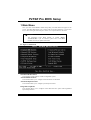
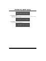
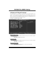
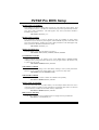
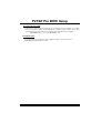
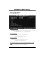
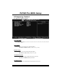
1
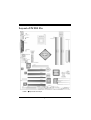
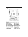
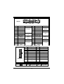
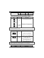
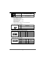
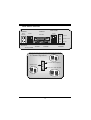
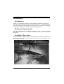
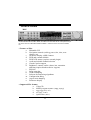
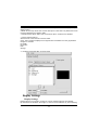
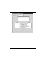
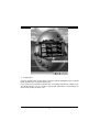
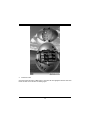
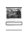
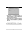
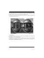
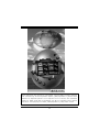
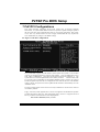
P P44TTS SE EP Prroo FCC Information and Copyright This equipment has been tested and found to c omply with the limits of a C lass B digital device, pursuant to Part 15 of the FCC Rules . T hese limits are designed to provide reasonable protection agains t harmful interference in a residential installation. This equipment generates , uses and can radiate radio frequency energy and, if not ins talled and used in accordance with the instructions, may c ause harmful interference to radio communications . There is no guarantee that interference will not occur in a partic ular installation. The vendor makes no representations or warranties with respec t to the contents here of and specially disclaims any implied warranties of merchantability or fitness for any purpose. F urther the vendor reserves the right to revise this publication and to make changes to the c ontents here of without obligation to notify any party beforehand. Duplication of this publication, in part or in whole, is not allowed without firs t obtaining the vendor’s approval in writing. The c ontent of this user’s manual is subject to be changed without notice and we will not be responsible for any mistakes found in this us er’s manual. A ll the brand and product names are trademarks of their respective c ompanies . i C Coonntteenntt LAYOUT OF P4TS E PRO ....................................................................... 1 COMPONENT INDEX............................................................................. 2 ENGLIS H................................................................................................... 3 P4TSE Pro Features ...................................................................................3 Package contents.......................................................................................5 How to set up Jumper.................................................................................6 CPU Installation.........................................................................................6 DDR DIMM Modules: DDRA1-2, DDRB1-2 ......................................................7 Installing DDR Module................................................................................8 Jumpers, Headers, Connectors & Slots.........................................................8 S TUDIOFUN!.......................................................................................... 16 Introduction............................................................................................. 16 Hardware Requirements............................................................................ 16 Installation Procedure............................................................................... 16 Booting to StudioFun!.............................................................................. 18 Media control.......................................................................................... 19 Control Panel.......................................................................................... 20 Software Details....................................................................................... 22 Select Region.......................................................................................... 24 Screensaver............................................................................................ 25 Display Settings....................................................................................... 26 File Manager............................................................................................ 27 WARPSPEEDER..................................................................................... 29 Introduction............................................................................................. 29 System Requirement................................................................................ 29 Installation .............................................................................................. 30 Usage..................................................................................................... 31 TROUBLE S HOOTING......................................................................... 39 ii Layout of P4TSE Pro NOTE: ●represents the f irst pin. 1 Component Index A. JKBV1: Po wer Sour ce Selection for Keyboard/ Mouse B. JUSBV1: Po wer Source Selection for USB C. Back Pan el Connector s D. JAUDIO1: Front Audio H eader E. PCI 1-5: Per ipheral Component Interconnect Slots F. JCDIN1: CD-ROM Audio-In Header G. U43: Wireless Audio Connector H. CNR1: Communication Net work Ri ser Slot I. U33: W ireless L AN Connector (optional) J. JW OL1: W ake On LAN H eader K. JSPDIF_OUT1: Digital Audio Connector L. JUSB2: Front USB Head er M. JUSBV3_4: Po wer Source Selection for USB N. JUSB3: Front USB Head er O. J1394A1: Front 1394 Header P. J1394B1: Front 1394 Header Q. JP ANEL1: Front Panel Connector R. JSF AN1: S ystem F an Header S. JG AME 1: Gam e Header T. RAID1-2: R aid Connectors U. JCL1: Case Op en Connector V. JCMOS 1: Clear CMOS Jump er W. JDJ1: Audio DJ Connector X. S AT A1-2: S eri al ATA Connectors Y. AGP 1: Acceler ated Gr aphic Port Slot Z. IDE1-2: Hard Disk Connectors A1. FDD1: Flopp y Disk Connector A2. DDRA1-2/ DDRB1-2: DDR DIMM Modules A3. JCF AN1: CPU Fan Connector A4. JATXPWR2: ATX Po wer Connector A5. JATXPWR1: ATX Po wer Connector A6. JUSBV2: 5V /5V SB S election for USB 2 English P4TS E Pro Features A. Hardware CPU Prov ides Socket-478. Supports the Intel Pentium 4 processor to 3.6 GHz+. Front Side Bus at 400/533/800MHz. Supports Hy per-Threading. Supports Northwood and Prescott CPU. (Willamette not supported) Chipset North Bridge: Intel 865PE. South Bridge: Intel ICH5R. Main Memory Supports one or two 64-bit wide DDR data channels with 1 or 2 DIMMs per-channel. Available bandwidth up to 3.2GB/s(DDR400) f or single-channel mode and 6.4GB/s (DDR 400) in dual channel mode. Supports 128-MB, 256-Mb, 512-Mb DDR technologies. Supports only x8, x16, DDR devices.( Does not support registered DIMMs) Supports four bank devices. Maximum memory size is 4GB. Super I/O Chip: ITE IT8712. Low Pin Count Interface. Prov ides the most commonly used legacy Super I/O functionality. Env ironment Control initiatives, - H/W Monitor - Fan Speed Controller - ITE's "Smart Guardian" f unction Slots Five 32-bit PCI bus master slots. One CNR slot. One AGP 4X/8X slot. On Board IDE Supports four IDE disk drives. Supports PIO Mode 5, Bride Mode and Ultra DMA 33/66/100 Bus Master Mode. Supports 2 Serial ATA (SATA) ports. - Compliant with SATA 1.0 specification 3 - Data transfer rates up to 1.5 Gb/ s LAN Chip: RTL8100B. Supports 10 Mb/s and 100 Mb/s auto-negotiation Half /Full duplex capability. Supports ACPI power management IEEE 1394A Chip Chip: VIA VT6307. Support 2 ports with transfer up to 400Mb/s. Serial ATA/RAID Chip: ICH5R with Intel® RAID Technology. Support RAID 0 (striping). Optimize data transfer rates for disk-intensive application. Features Benefits Intel ® 82801ER I/O Controller Industry’s first desktop RAID controller Hub integrated directly into the chipset Dual Serial ATA Controllers with Exceptional storage performance utilizing the RAID 0 Support next-generation hard disk interface technology RAID BIOS ROM Integrated into system BIOS, enables pre-OS RAID creation, naming and deletion RID Migration Capability Seamless migration from a single hard drive to a RAID 0 array with no OS reinstallation required Intel Application Accelerator RAID Driv er with full management and status Edition reporting of y our RAID array including detailed reporting of storage devices On Board AC’97 Sound Codec Chip: CMI9739A/ 9760. Compliant with AC’97 specification. AC97 2.2 interface. Supports 6 channels . On Board Peripherals a.Rear side 2 serial ports. 1 parallel port. (SPP/EPP/ECP mode) Audio ports in vertical position. 1 RJ-45 LAN jack. Supports PS/2 mouse and PS/2 key board. 4 USB2.0 ports. 1 1394A Firewire ports. 4 b.Front Side 1 floppy port supports 2 FDDs with 360K, 720K, 1.2M, 1.44M and 2.88Mbytes. 4 USB2.0 ports. 1 front audio header. 1 S/PDIF header. 1 1394A Firewire ports. Dimensions ATX Form Factor: 24.4 X 30.5cm (W X L) B. BIOS & Software BIOS Award legal BIOS. Supports APM1.2. Supports ACPI. Supports USB Function. Software Supports Warpspeeder™, 9th Touch™, FLASHER™ and StudioFun! ™. Off ers the highest performance for Windows 98 SE, Windows 2000, Windows Me, Windows XP, SCO UNIX etc. Package contents HDD Round Cable X 1 FDD Round Cable X 1 User’s Manual X 1 Fully Setup Driv er CD X 1 StudioFun! Application CD X 1 USB 2.0 Cable X 1 (optional) S/PDIF Cable X 1 Rear I/O Panel f or Micro ATX Case X 1 Serial ATA Cable X 1 Serial ATA Power Switch Cable X 1 IEEE 1394 Cable X 1 (optional) 5 How to set up Jumper The illustration shows to how set up jumper. When the Jumper cap is placed on pins, the jumper is “close”. IF no jumper cap is placed on the pins, the jumper is ”open”. The illustration shows a 3-pin jumper whose pin1and 2 are “close” when jumper cap is placed on these 2 pins. Jumper open Jumper close Pin1-2 close CPU Installation Step1: Pull the lever sideway s away from the socket and then raise the lev er up to a 90-degree angle. Step2: Look f or the white dot/cut edge. The white dot/cut edge should point wards the lev er piv ot. The CPU will f it only in the correct orientation. Step3: Hold the CPU down f irmly, and then close the lever to complete the installation. Step4: Put the CPU Fan on the CPU and buckle it. Connect the CPU fan power cable to the JCFAN1. This completes the installation. Step1 Step2 Step3 6 Step4 CPU Fan Headers: JCFAN1 1 JCFAN1 Pin Assignment 1 Ground 2 +12V 3 FAN RPM rate Sense S ystem Fan Headers: JSFAN1 Pin Assignment 1 Ground 2 +12V 3 FAN RPM rate Sense 1 JSFAN1 DDR DIMM Modules: DDRA1-2, DDRB1-2 Supports up to four DDR DIMMs(two DIMMs per channel), single-sided and/ or double-sided. For Dual Channel Operation, DIMMs must be populated in identical pairs. It has to be the combination of DDRA1+DDRB1 (Blue DIMMs) or DDRA2+DDRB2 (white DIMMs). Dual Channel Guidelines Matched DIMM conf iguration in each channel % Same Density (128MB, 256MB, 512MB, 1GB, etc.) % Same DRAM technology (128M-bit, 256M-bit, or 512M-bit) % Same DRAM bus width (x8 or x16) % Both either single-sided or dual-sided Matched in both Channel A and Channel B memory channels % Populate symmetrical memory slots Optimal platf orm performance with Dual Channel, DDR400, matched DIMMs % Fully loaded configurations can be single or double sided DIMMs % Lightly loaded configurations need to be double sided DIMMs When not using DDR400, best perf ormance obtained with 7 % Symmetrical DIMM population and matched double-sided DIMMs % Lightly loaded configuration Dual Channel Configuration Table • Dual Channel Configuration Table DIMM Slot DDRA1 DDRA2 DDRB1 DDRB2 System Density Lightly Loaded 128MB -Config Lightly Loaded Config Fully Loaded 128MB -Config 128MB -- 1GB 1GB 256MB -- 1GB 2GB 128MB -- 128MB -- 1GB 1GB 128MB -- 128MB -- 128MB -- 1GB 1GB 1GB 256MB -2GB 512MB -4GB DRAM Access Time: 2.5V Unbuffered/ no registered (without ECC) DDR SDRAM PC2100/ PC2700/ PC3200 Ty pe required. DRAM Ty pe: 128MB/ 256MB/ 512MB/ 1GB DIMM Module (184 pin) Installing DDR Module 1. Unlock a DIMM slot by pressing the retaining clips outward. Align a DIMM on the slot such that the notch on the DIMM matches the break on the slot. 2. Insert the DIMM v ertically and firmly into the slot until the retaining chip snap back in place and the DIMM is properly seated. Jumpers, Headers, Connectors & Slots Floppy Disk Connector: FDD1 The motherboard provides a standard f loppy disk connector that supports 360K, 720K, 1.2M, 1.44M and 2.88M floppy disk types. This connector supports the prov ided f loppy drive ribbon cables. Hard Disk Connectors: IDE1/ IDE2 The motherboard has a 32-bit Enhanced PCI IDE Controller that provides PIO Mode 0~5, Bus Master, and Ultra DMA 33/ 66/ 100 f unctionality. It has two HDD connectors IDE1 (primary) and IDE2 (secondary). 8 The IDE connectors can connect a master and a slave driv e, so you can connect up to f our hard disk driv es. The f irst hard drive should alway s be connected to IDE1. Peripheral Component Interconnect Slots: PCI1-5 This motherboard is equipped with 5 standard PCI slots. PCI stands f or Peripheral Component Interconnect, and it is a bus standard for expansion cards. This PCI slot is designated as 32 bits. Accelerated Graphics Port S lot: AGP1 Y our monitor will attach directly to that v ideo card. This motherboard supports video cards for PCI slots, but it is also equipped with an Accelerated Graphics Port (AGP). An AGP card will take advantage of AGP technology f or improved video efficiency and performance, especially with 3D graphics. Communication Network Riser S lot: CNR1 The CNR specification is an open Industry Standard Architecture, and it defines a hardware scalable riser card interf ace, which supports modem only. Serial ATA Connector: JS ATA1/JS ATA2 The motherboard has a PCI to SATA Controller with 2 channels SATA interf ace, it satisfies the SATA 1.0 spec and can transf er data with 1.5GHz speed. Front Panel Connector: JPANEL1 9 P WR_LED ON/OF F S LP JPANEL1 IR 2 24 1 23 S PK HLED RST IR Pin 1 Assignment +5V Function Speaker Pin 2 Assignment Sleep Control Function Sleep 3 NA Connector 4 Ground Button 5 NA 6 NA NA 7 Speaker 8 Power LED (+) 9 HDD LED (+) Hard Drive 10 Power LED (+) POWER LED 11 HDD LED (-) LED 12 Power LED (-) 13 Ground Reset 14 Power Button Power-on 15 Reset Control Button 16 Ground Button 17 NA 18 KEY 19 NA IrDA 20 KEY IrDA 21 +5V Connector 22 Ground Connector 23 IRTX 24 IRRX Power Connectors: JATXPWR1/ J ATXPWR2 10 20 1 11 J ATXPWR1 PIN 1 Assignment +3.3V PIN 11 Assignment +3.3V 2 3 +3.3V Ground 12 13 -12V Ground 4 5 +5V Ground 14 15 PS_ON Ground 6 +5V 16 Ground 7 8 Ground PW_OK 17 18 Ground -5V 9 Standby Voltage +5V +12V 19 +5V 20 +5V 10 1 3 PIN Assignment 10 PIN Assignment 1 +12V 3 Ground 2 +12V 4 Ground Power S ource Selection for Keyboard/ Mouse: JKBV1 JKBV1 Assignment Description +5V for key board and mouse 1 +5V 3 Pin 1-2 close 1 +5V Standby Voltage 3 PS/2 Mouse and PS/2 Keyboard are powered with +5V standby v oltage Pin 2-3 close Note: In order to power-on keyboard and mouse function, “JKBV1” jumper cap should be placed on pin 2-3. Power S ource Selection for USB: JUSBV1/ JUS BV2/ JUS BV3_4 JUSBV1/JUSBV2/ JUSBV3_4 1 3 Assignment Description +5V JUSBV1: 5V for JUSB1 port JUSBV2: 5V for JRJ45USB1 port Pin 1-2 close JUSBV3_4: 5V for JUSB2/3 ports 1 3 Pin 2-3 close +5V Standby Voltage JUSBV1: JUSB1 port powered with standby v oltage of 5V JUSBV2: JRJ45USB1 port powered with standby voltage of 5V JUSBV3_4: JUSB2/3 ports powered with standby voltage of 5V Note: In order to pow er-on USB devices function, “JUSBV1/JUSBV2/ JUSBV3_4” jumper cap should be placed on pin 2-3 individually. Clear CMOS Jumper: JCMOS1 JCMOS1 Assignment 11 1 3 1 3 Pin 1-2 Close Normal Operation (default) Pin 2-3 Close Clear CMOS Data ※ Clear CM OS Procedures: 1. Remov e AC power line. 2. Set the jumper to “Pin 2-3 Close”. 3. Wait for fiv e seconds. 4. Set the jumper to “Pin 1-2 Close”. 5. Power on the AC. 6. Reset y our desired password or clear the CMOS data. Case Open Connector: JCL1 2 1 JCL1 Pin Assignment 1 Case Open Signal 2 Ground Serial ATA Connector: JS ATA1/ JS ATA2 65 3 2 7 4 1 JS ATA1/ JSATA2 Pin Assignment Pin Assignment 1 Ground 2 TX+ 4 TX- 4 Ground 5 RX- 6 RX+ 7 Ground AUD IO DJ Connector: JDJ1 5 1 JDJ1 Pin Assignment Pin Assignment 1 SMBDATA 2 SMBCLK 3 INT_B 4 KEY 5 ATX_PWROK 12 Game Header: JGAME1 15 1 16 2 JG AME1 Pin Pin 1 Assignment +5V 2 Assignment +5V 3 GPSB1 4 GPSA1 5 GPX2 6 GPX1 7 MIDI-OUT 8 Ground 9 GPY 2 10 Ground 11 GPSB2 12 GPY1 13 MIDI-IN 14 GPSA2 15 NA 16 +5V CD-ROM Audio-In Header: JCDIN1 1 JCDIN1 Pin Assignment 1 Left Channel Input 2 Ground 3 Ground 4 Right Channel Input Front Panel Audio Header: JAUDIO1 2 1 14 13 J AUDIO1 Pin Assignment Pin Assignment 1 Mic In 2 Ground 3 Mic Power 4 Audio Power 5 RT Line Out 6 RT Line Out 7 Reserv ed 8 Key 9 LFT Line Out 10 LFT Line Out 11 RT Line In 12 RT Line In 13 LET Line In 14 LET Line In 13 Digital Audio Connector: JS PDIF_OUT1 Pin 1 JSPDIF_OUT1 1 Assignment +5V 2 SPDIF_OUT 3 Ground Wake On LAN Header: JWO L1 1 JWOL1 Pin 1 Assignment +5V_SB 2 3 Wake up Ground Front USB Header: JUSB2/3 Pin 9 10 1 2 JUSB2/3 Assignment +5V(f used) USBUSB+ Ground Pin 1 3 5 7 2 4 6 8 Assignment +5V(fused) USBUSB+ Ground 9 KEY 10 NC Front 1394 Header: J1394A1/ J1394B1 Pin 9 10 1 2 J1394 A1/ B1 Assignment A+ Ground B+ +12V Pin 1 3 5 7 2 4 6 8 Assignment AGround B+12V 9 KEY 10 Ground 14 Back Panel Connectors JKBMS1 PS/2 Mouse JRJ45USB1 JPRNT1 LAN 1394 Parallel Line In Speaker Out Mic In PS/2 Keyboard USB COM1 J1394_USB1 JCOM1 COM2 USB JCOM2 JAUDIO 6 Channe l Spe akers Line In/ Rear Speaker Speaker Out Mic In/ Center & Bass 15 StudioFun! Introduction StudioFun! is a media-player based on optimized GNU/Linux distribution. It plays DVD, VCD, MP3, Audio CD and various other known f ile formats. You can take snapshots of video and customize the sav ed images as screensavers. Y ou can also store the images on USB mass storage dev ices like f lash disks and USBf loppy disks. Hardware Requirements The supported hardware list of StudioFun! grows up ev ery day. So please check the hwreq.txt located in the root of StudioFun! Installation CD to get the most updated inf ormation. Installation Procedure Insert the StudioFun! Installation CD in a CD/DVD ROM drive and let the system boot through the CD. The disk will boot and bring up the grub boot loader installation menu. Two options are specified. 16 Installation This option will do the basic installation of the distribution. The installation works on pre-installed windows or GNU/Linux distribution. On selecting the ’installation’ option the installer boots and displays a dialog box indicating the space required and waits f or a confirmation. Selecting Ok will continue the installation while selecting Cancel will terminate the installation and reboot the machine. If Windows or GNU/Linux is the only OS installed on the hard disk with no f ree space, it will resize the partition, either NTFS or FAT32 or ext2, and install StudioFun!. In case the hard disk has a 128MB of free space av ailable, the installation will use the free space. After installing the base system you will be prompted to select the resolution from the f ollowing choices 1. 1024x768 (recommended) 2. 800x600 3. 640x480 Select the desired resolution. The default is 1024x768f or high-end graphics. Next y ou will be prompted to choose the DVD area/region selection code. Choose this based on the ty pe of DVDs y ou will be playing. The installation procedure will then probe f or the ty pe of mouse installed. The distribution currently supports PS/2, USB and Serial mice. In case of serial mouse you will hav e to mov e the mouse when prompted. The other two are probed and installed automatically. The installation procedure will now finish, the CD is ejected and a dialog box prompting to reboot the machine is display ed. Press OK button and enjoy StudioFun!. 3.1.1 Error Messages 1. Media corrupted!! Please check the media! The CD-ROM is corrupted. 2. Extraction of base system failed!! Please try again later!! The CD-ROM is corrupted. 3. Unsupported hardware f ound, Aborting... If you try to install StudioFun! on an unsupported and undocumented hardware the abov e error message is popped. 4. No device found! This error message is given if there is no hard disk in the system. 17 Recovery In case of a MBR corruption, this option should be used. It will automatically probe the hard disk master boot record and f ind out the installed operating system(s). On success it will re-install the boot loader with correct options in the MBR. Any custom boot loader option specified from other GNU/Linux installations will get ov er written by the newly probed one. Booting to StudioFun! After Installation is ov er, remove the CD f rom the CD-ROM and restart the machine. After the machine reboots, you will get the GRUB boot loader menu screen. Select the StudioFun option to boot to the StudioFun! partition. 18 After complete boot up, you get to the main Desktop screen. The f ollowing section is a complete description of the Desktop application. Desktop This is the main shell of the StudioFun software. It basically comprises of two categories, one is the main "media control" part and the other is the "control panel". Media control The media control part of the Desktop has the f ollowing controls: 1. VCD This control will glow whenev er a VCD is detected in a DVD/CD-ROM driv e. The VCD will be auto-played only when it is put in to the drive when the Desktop (StudioFun! shell) is up and running, otherwise, the control will simply glow to inform the user about a VCD 19 present in the DVD/CD-ROM driv e. 2. DVD This control will glow whenev er a DVD is detected in a DVD drive. The DVD will be auto-played only when it is put in to the drive when the Desktop (StudioFun! shell) is up and running, otherwise, the control will simply glow to inform the user about a DVD present in the DVD/CD-ROM. 3. MP3 This control will glow whenev er a MP3 is detected in a DVD/CD-ROM driv e. The MP3 will be auto-played only when it is put in to the drive when the Desktop (StudioFun! shell) is up and running, otherwise, the control will simply glow to inf orm the user about a MP3 present in the DVD/CD-ROM driv e. 4. AUD IO This control will glow whenev er a AUDIO is detected in a DVD/CD-ROM driv e. The AUDIO will be auto-play ed only when it is put in to the driv e when the Desktop (StudioFun! shell) is up and running, otherwise, the control will simply glow to inf orm the user about a AUDIO present in the DVD/CD-ROM driv e. 5. FILE This control will glow whenev er a File CD (CDs with other media type f iles) is detected in a DVD/CD-ROM drive. The File CD will be auto-played only when it is put in to the driv e when the Desktop (StudioFun! shell) is up and running, otherwise, the control will simply glow to inf orm the user about a File CD present in the DVD/CD-ROM driv e. 6. EJECT MEDIA This control when clicked will eject any MP3 or File CDs f rom any of the DVD/CDROM driv es. In case there were no MP3 or File CDs it will eject the def ault medium, (i.e.), the CD-ROM driv e in case if the user has both DVD/CD-ROM driv e or else it will eject the def ault DVD/CD-ROM drive. 7. EXIT This is the "Power on/off" control of the Desktop (StudioFun! shell). Control Panel Control panel part has fiv e icons, which are shortcuts to other applications present in the StudioFun software. Tool tips are provided on the icons when the mouse is rolled ov er them. 20 1. Select Region Clicking this icon will inv oke the application for selection DVD region settings. Ref er to section 5.2 Select DVD Region application for more details. 2. S creensaver Clicking this icon will inv oke the screensav er application. Ref er to section 5.3 Screensaver f or more details. 3. Display Settings Clicking this icon will inv oke the application for changing the screen resolutions. Refer to section 5.4, Display Settings f or more details . 4. File Manager Clicking this icon will inv oke the file manager. Ref er to section 5.6 File manager f or more details. When user has a DVD and a CD-ROM Drive: If user has both DVD and a CD-ROM drive, DVD drive will be given the pref erence when both the drives hold v alid media in them, i.e., if the CD-ROM drive has a media and a DVD driv e also has a media, and the StudioFun! is started, then the media inside the DVD driv e will be play ed. If in case the media in CD-ROM takes a longer time to get recognized than the media inside the DVD drive, the media in the CD-ROM will be played, once if it is recognized. Other general user scenarios When a user clicks on any of the media-controls when it is not glowing, except eject media and exit, the media-play er will just come up and wait for user input. NO DUPLICATE INSTANCE OF ANY APPLICATION WILL BE ALLOWED TO RUN. 21 Software Details XIN E XINE is a multimedia play er. It plays back Audio CD, DVD, and VCD. It also decodes multimedia files like AVI, MOV, WMV, and MP3 from local disk driv es. It interprets many of the most common multimedia f ormats available - and some of the uncommon f ormats, too. • Features of Xine a. Skinnable GUI b. Navigation controls (seekin g, p ause, fast, slow, next chap ter, etc) c. On Screen Display (OSD) features d. DVD and external subtitles e. DVD/VCD menus (requ ires external plu gin) f. Audio and subtitle channel selection g. Closed Cap tion supp ort h. Brightness, contrast, audio volume, hue, saturation adjusting requ ires hardware/driver supp ort) i. Play lists j. Image snap shot k. Audio resamp ling l. Software de-interlacin g algorithms m. Configuration dialo g n. Asp ect ratio changin g o. Fullscreen display • S upported File formats a. Video CD b. MPEG p rogram streams (.mp g, .mpeg) c. ogg (.o gg) avi (.avi) d. asf (.asf, .wmv) e. QuickTime (.mov) 22 a. f. MPEG-Video (.mp v, .m2v) g. MPEG-Audio (.mp 2, .mp 3) h. WAV (.wav) Video Codecs i. MPEG 1/2 j. MPEG 4 (aka Op enDivX) k. M S MPEG 4 Chap ter 5: Software Details 10 l. Windows Media Video 7 m. M otion JPEG • Remote Control support. a. Infrared interface b. User-friendly • Usage of S tudioFun! with CelomaChrome skin a. Select VCD button to p lay a VCD disc b. Select DVD button to p lay a DVD disc c. Select CDDA button to p lay a Audio cd d. Select next chap ter or MRL (>>|) button to play next track in Audio CD, VCD and M P3 songs and to p lay next chap ter in DVD e. Select previous chap ter or M RL (|<<) button to p lay p revious track in Audio CD, VCD and MP3 songs and to p lay p revious chapter in DVD f. Select slow motion (<<) button to p lay the video / audio in slow motion (Select p lay button after reaching the required p osition) g. Select fast motion (>>) button to p lay the video / audio in fast motion (Select p lay button after reaching the requ ired p osition) h. Select subs + / - button to select the app rop riate subtitle (Usable while play ing i. Select audio + / - button to select the app rop riate audio track (For examp le when j. The DVD contains one audio track in En glish and the other with some other language, k. Usable while play ing DVD’s) 23 l. m. n. o. p. q. r. s. j. Select hide button to hide the control p anel of the play er k. Select menu button to use menu’s while p lay ing DVD l. Select control button to adjust brightness / color Select setup button to modify the settings of the p layer Select f.scr button to show the video outp ut of the p lay er in full screen mode Select snap button to take a snapshot of the currently p lay ing video Select plist button to add / remove / manage play list Select mrl button to add new file to play Error Messages The following error message is given if an unknown file format is selected through Xine M RL browser and p lay ed. While p laying mp3 files, if the user stops p lay ing and tries to select the DVD button, then the following error message is shown Select Region Overview Select region is a utility to set a DVD region. With the help of this application user can set or change a DVD region. Only one region can be set at a time. About S elect Region With the help of this application y ou can set a region for DVD. Only one region can be set at a time. If y ou keep the mouse pointer on any region, y ou canv iew the countries, which comes under that region. Ok - Click to set the selected region. Cancel - Click to quit the application. How to select DVD region Y ou can select only one region at a time. Y ou can change your selection by clicking on any other region. • A snapshot of the application is shown below: 24 Screensaver S creensaver The xscreensaver daemon waits until the keyboard and mouse hav e been idle for a period, and then runs a graphics demo chosen at random. The demo is terminated as soon as there is any mouse or keyboard activ ity. The xscreensav er-demo program is the graphical user interf ace to xscreensaver. It lets y ou tune the v arious parameters used by the xscreensaver daemon, and browse through the graphics demos. StudioFun! comes with xscreensaver when you click on the screensaver icon the application comes up. Then user can choosev arious graphics demos like chbg,halo,hypercube or hyperball. S creensaver comes with various options • Prev iew Option: When a user selects a particular graphics demo and clicks on preview button the demo comes up. • Blank After Option: The screensaver will blank the screen after the keyboard and mouse hav e been idle def ault time is 1minute and user can change the settings. • Cycle After Option: When screensav er is running this cycle time defines the time limit f or each screensaver. • Mode Screensaver comes with v arious modes: 1. Random Screen Saver: When user chooses this option, Screensav er cycles through v arious graphics demos randomly 25 2. Only one Screen Saver: When user chooses this option, screensaver displays only one graphics demo. 3. Blank Screen Only: When user chooses this option, screensaver only blanks the screen instead of displaying the graphics demo. 4. Disable Screen Saver: When user chooses this option, screensaver is disabled. • Various Graphics Demos XScreensav er comes with various screensaver Chbg: This screensaver displays the images stored in StudioFun! the time gap between images is 5 seconds. Hy perball Hy percube Halo Strange • A snapshot of the application is shown below: Display Settings Display Settings Display setting is a program to change the current resolution settings of the Display. By def ault user of StudioFun will be given a choice to select between any of the f ollowing 26 three resolutions. • 640x480 • 800x600 • 1024x768 The current resolution of the Display will be selected by default. It requires restart of the StudioFun to reflect the changes made. File Manager Overview File manger is an utility to copy f iles from deferent devices to hard disk and v ice versa. User can copy f iles from dev ices such as, f loppy, cdrom and f lashdisk to hard disk. And also f rom hard disk to floppy and flashdisk. About File manager The hard disk f iles are stored in a directory called “/studiof un” on the hard disk. Y ou can also delete f iles from hard disk, but you cannot deletef iles from any device. Select device - Contains the device names /f loppy, /cdrom and /f lashdisk. Select a device f rom/to whichyou want to copy files. Please double click the device option twice to mount the device. List Directories - Shows the list of directories of the selected device after double clicking it. Floppy /cdrom/Flashdisk - Shows the contents of the selected directory from the “List directories“f ield after double clicking it. Hard disk - Shows the contents of a directory called “/studiof un”. Add (>>) - Click to copy selected files from a device to hard disk. Add (<<) - Click to copy selected files from hard disk to a dev ice. Remov e - Click to delete files from hard disk. Exit - Click to quit the application. 27 28 WarpSpeeder Introduction [ WarpSpeeder™ ], a new powerf ul control utility, f eatures three user-f riendly functions including Ov erclock Manager, Ov ervoltage Manager, and Hardware Monitor. With the Ov erclock Manager, users can easily adjust the frequency they prefer orthey can get the best CPU perf ormance with just one click. The Ov ervoltage Manager, on the other hand, helps to power up CPU core v oltage and Memory voltage. The cool Hardware Monitor smartly indicates the temperatures, voltage and CPU fan speed as well as the chipset inf ormation. Also, in the About panel, you can get detail descriptions about BIOS model and chipsets. In addition, the frequency status of CPU, memory, AGP and PCI along with the CPU speed are synchronically shown on our main panel. Moreov er, to protect users' computer systems if the setting is not appropriate when testing and results in system f ail or hang, [ WarpSpeeder™ ] technology assures the system stability by automatically rebooting the computer and then restart to a speed that is either the original system speed or a suitable one. System Requirement OS Support: Windows 98 SE, Windows Me, Windows 2000, Windows XP DirectX: DirectX 8.1 or above. (The Windows XP operating system includes DirectX 8.1. If y ou use Windows XP, y ou do not need to install DirectX 8.1.) 29 Installation 1. Execute the setup execution f ile, and then the following dialog will pop up. Please click “Next” button and f ollow the default procedure to install. 2. When y ou see the f ollowing dialog in setup procedure, it means setup is completed. If the “Launch the WarpSpeeder Tray Utility” checkbox is checked, the Tray Icon utility and [WarpSpeeder™] utility will be automatically and immediately launched after y ou click “Finish” button. 30 Usage The following figures are just only for reference, the screen printed in this user manual will change according to your motherboard on hand. [WarpSpeeder™] includes 1 tray icon and 5 panels: 1. Tray Icon: Whenev er the Tray Icon utility is launched, it will display a little tray icon on the right side of Windows Taskbar. 31 This utility is responsible f or conveniently invoking [WarpSpeeder™] Utility. Y ou can use the mouse by clicking the left button in order to inv oke [WarpSpeeder™] directly from the little tray icon or you can right-click the little tray icon to pop up a popup menu as following f igure. The “Launch Utility” item in the popup menu has the same function as mouse left-click on tray icon and “Exit” item will close Tray Icon utility if selected. 2. Main Panel If you click the tray icon, [ WarpSpeeder™ ] utility will be inv oked. Please ref er do the following f igure; the utility’s f irst window y ou will see is Main Panel. Main Panel contains features as follow s: a. Display the CPU Speed, CPU external clock, Memory clock, AGP clock, and PCI clock inf ormation. b. Contains About, Voltage, Overclock, and Hardware Monitor Buttons f or invoking respective panels. c. With a user-friendly Status Animation, it can represent 3 ov erclock percentage stages: Man walking => ov erclock percentage from 100% ~ 110 % Panther running => overclock percentage from 110% ~ 120% Car racing => ov erclock percentage f rom 120% ~ above 32 3. Voltage Panel Click the Voltage button in Main Panel, the button will be highlighted and the Voltage Panel will slide out to up as the f ollowing figure. In this panel, you can decide to increase CPU core voltage and Memory voltage or not. The def ault setting is “No”. If y ou want to get the best performance of ov erclocking, we recommend y ou click the option “Y es”. 33 4. Overclock Panel Click the Ov erclock button in Main Panel, the button will be highlighted and the Overclock Panel will slide out to left as the f ollowing figure. 34 Overclock Panel contains the these features: a. “–3MHz button”, “-1MHz button”, “+1MHz button”, and “+3MHz button”: provide user the ability to do real-time overclock adjustment. Warning: Manually overclock is potentially dangerous, especially w hen the overclocking percentage is over 110 %. We strongly recommend you verify every speed you overclock by click the Verify button. Or, you can just click Auto overclock button and let [ WarpSpeeder™ ] automatically gets the best result for you. b. “Recovery Dialog button”: Pop up the following dialog. Let user select a restoring way if system need to do a f ail-safe reboot. 35 d. “Auto-ov erclock button”: User can click this button and [ WarpSpeeder™ ] will set the best and stable performance and frequency automatically. [ WarpSpeeder™ ] utility will execute a series of testing until system f ail. Then system will do f ail-saf e reboot by using Watchdog f unction. After reboot, the [ WarpSpeeder™ ] utility will restore to the hardware def ault setting or load the verif ied best and stable frequency according to the Recovery Dialog’s setting. e. “Verify button”: User can click this button and [ WarpSpeeder™ ] will proceed a testing f or current frequency. If the testing is ok, then the current f requency will be sav ed into system registry. If the testing f ail, system will do a fail-safe rebooting. After reboot, the [ WarpSpeeder™ ] utility will restore to the hardware default setting or load the verif ied best and stable frequency according to the Recovery Dialog’s setting. Note: Because the testing programs, invoked in Auto-overclock and Verify, include DirectDraw , Direct3D and DirectShow tests, the DirectX 8.1 or newer runtime library is required. And please make sure your display card’s color depth is High color (16 bit) or True color( 24/32 bit ) that is required for Direct3D rendering. 36 5. Hardware Monitor Panel Click the Hardware Monitor button in Main Panel, the button will be highlighted and the Hardware Monitor panel will slide out to left as the f ollowing figure. In this panel, you can get the real-time status information of y our system. The information will be ref reshed ev ery 1 second. 6. About Panel Click the About button in Main Panel, the button will be highlighted and the About Panel will slide out to up as the following f igure. In this panel, you can get model name and detail inf ormation in hints of all the chipset that are related to overclocking. Y ou can also get the mainboard’s BIOS model and the Version number of [ WarpSpeeder™ ] utility. 37 Note: Because the overclock, overvoltage, and hardware monitor features are controlled by several separate chipset, [ WarpSpeeder™ ] divide these features to separate panels. If one chipset is not on board, the correlative button in Main panel will be disabled, but will not interfere other panels’ functions. This property can make [ WarpSpeeder™ ] utility more robust. 38 Trouble Shooting PROBABLE SOLUTION No power to the system at all Power light don’t * Make sure power cable is securely plugged in illuminate, fan inside power supply does not turn * Replace cable on. Indicator light on keyboard does not turn on * Contact technical support PROBABLE SOLUTION System inoperative. Keyboard lights are on, * Using even pressure on both ends of the power indicator il ghts are lit, hard drive is DIMM, press down firmly until the module snaps into place. spinning. PROBABLE SOLUTION System does not boot from hard disk drive, can * Check cable running from disk to diskcontroller be booted from CD-ROM drive. board. Make sure both ends are securely plugged in; check the drive type in the standard CMOS setup. * Backing up the hard drive is extremely important. All hard disks are capable o breaking down at any time. PROBABLE SOLUTION System only boots from CD-ROM. Hard disk can * Back up data and applications files. Reforma be read and applications can be used but the hard drive. Re-install applications and data using backup disks. booting from hard disk is impossible. PROBABLE SOLUTION Screen message says “Invalid Configuration” or * Review system’s equipment . Make sure “CMOS Failure.” correct information is in setup. PROBABLE SOLUTION Cannot boot system after installing second hard * Set master/slave jumpers correctly. drive. * Run SET UP program and select correct drive types. Call drive manufacturers for compatibility with other drives. 39 05/05/2003 40 P4TSE Pro BIOS Setup BIOS Setup........................................................................................1 1 Main Menu..................................................................................................... 3 2 Standard CMOS Features .............................................................................. 6 3 Advanced BIOS Features............................................................................... 9 4 Advanced Chipset Features.......................................................................... 12 5 Integrated Peripherals .................................................................................. 15 6 Power Management Setup ........................................................................... 20 7 PnP/PCI Configurations ............................................................................... 24 8 PC Health Status .......................................................................................... 26 9 Frequency Control ....................................................................................... 28 i P4TSE Pro BIOS Setup BIOS Setup Introduction This manual discussed Award™ Setup program built into the ROM BIOS. The Setup program allows users to modify the basic system configuration. This special information is then stored in battery-backed RAM so that it retains the Setup information when the power is turned off. The Award BIOS™ installed in your computer system’s ROM (Read Only Memory) is a custom version of an industry standard BIOS. This means that it supports Intel Pentium ® 4 processor input/output system. The BIOS provides critical low-level support for standard devices such as disk drives and serial and parallel ports. Adding important has customized the Award BIOS™, but nonstandard, features such as virus and password protection as well as special support for detailed fine-tuning of the chipset controlling the entire system. The rest of this manual is intended to guide you through the process of configuring your system using Setup. Plug and Play Support These AWARD BIOS supports the Plug and Play Version 1.0A specification. ESCD (Extended System Configuration Data) write is supported. EPA Green PC Support This AWARD BIOS supports Version 1.03 of the EPA Green PC specification. APM Support These AWARD BIOS supports Version 1.1&1.2 of the Advanced Power Management (APM) specification. Power management features are implemented via the System Management Interrupt (SMI). Sleep and Suspend power management modes are supported. This AWARD BIOS can manage power to the hard disk drives and video monitors . ACPI Support Award ACPI BIOS support Version 1.0 of Advanced Configuration and Power interface specification (ACPI). It provides ASL code for power management and device configuration capabilities as defined in the ACPI specification, developed by Microsoft, Intel and Toshiba. 1 P4TSE Pro BIOS Setup PCI Bus Support This AWARD BIOS also supports Version 2.1 of the Intel PCI (Peripheral Component Interconnect) local bus specification. DRAM Support DDR DRAM (Double Data Rate Synchronous DRAM) are supported. Supported CPUs This AWARD BIOS supports the Intel Pentium ® 4 CPU. Using Setup In general, you use the arrow keys to highlight items, press <Enter> to select, use the <PgUp> and <PgDn> keys to change entries, press <F1> for help and press <Esc> to quit. The following table provides more detail about how to navigate in the Setup program by using the keyboard. Keystroke Up arrow Down arrow Left arrow Right arrow Move Enter PgUp key PgDn key + Key - Key Esc key F1 key F5 key F7 key F10 key Function Move to previous item Move to next item Move to the item on the left (menu bar) Move to the item on the right (menu bar) Move to the item you desired Increase the numeric value or make changes Decrease the numeric value or make changes Increase the numeric value or make changes Decrease the numeric value or make changes Main Menu – Quit and not save changes into CMOS Status Page Setup Menu and Option Page Setup Menu – E xit Current page and return to Main Menu General help on Setup navigation keys Load previous values from CMOS Load the optimized defaults Save all the CMOS changes and exit 2 P4TSE Pro BIOS Setup 1 Main Menu Once you enter Award BIOS™ CMOS Setup Utility, the Main Menu will appear on the screen. The Main Menu allows you to select from several setup functions. Use the arrow keys to select among the items and press <Enter> to accept and enter the sub-menu. 0 WARNING The information about BIOS defaults on manual (Figure 1,2,3,4,5,6,7,8,9) is just for reference, please refer to the BIOS installed on board, for update information. Figure 1. Main Menu Standard CMOS Features This submenu contains industry standard configurable options. Advanced BIOS Features This submenu allows you to configure enhanced features of the BIOS. Advanced Chipset Features This submenu allows you to configure special chipset features. Integrated Peripherals This submenu allows you to configure certain IDE hard drive options and Programmed Input/ Output features. 3 P4TSE Pro BIOS Setup Power Management Setup This submenu allows you to configure the power management features. PnP/PCI Configurations This submenu allows you to configure certain “Plug and Play” and PCI options. PC Health Status This submenu allows you to monitor the hardware of your system. Frequency Control This submenu allows you to change CPU Vcore Voltage and CPU/PCI clock. (However, this function is strongly recommended not to use. Not properly change the voltage and clock may cause CPU or M/B damage!) Load Optimized Defaults This selection allows you to reload the BIOS when the system is having problems particularly with the boot sequence. These configurations are factory settings optimized for this system. A confirmation message will be displayed before defaults are set. Set Supervisor Password Setting the supervisor password will prohibit everyone except the supervisor from making changes using the CMOS Setup Utility. You will be prompted with to enter a password. Set User Password If the Supervisor Password is not set, then the User Password will function in the same way as the Supervisor Password. If the Supervisor Password is set and the User Password is set, the “User” will only be able to view configurations but will not be able to change them. Save & Exit Setup Save all configuration changes to CMOS(memory) and exit setup. Confirmation message will be displayed before proceeding. 4 P4TSE Pro BIOS Setup Exit Without Saving Abandon all changes made during the current session and exit setup. Confirmation message will be displayed before proceeding. Upgrade BIOS This submenu allows you to upgrade bios. 5 P4TSE Pro BIOS Setup 2 Standard CMOS Features The items in Standard CMOS Setup Menu are divided into 10 categories. Each category includes no, one or more than one setup items. Use the arrow keys to highlight the item and then use the<PgUp> or <PgDn> keys to select the value you want in each item. Figure 2. Standard CMOS Setup 6 P4TSE Pro BIOS Setup Main Menu Selections This table shows the selections that you can make on the Main Menu. Item Options Date mm : dd : yy Set the system date. Note that the ‘Day’ automatically changes when you set the date. Time hh : mm : ss Set the clock. IDE Primary Master Options are in its sub menu. Press <Enter> to enter the sub menu of detailed options IDE Primary Slave Options are in its sub menu. Press <Enter> to enter the sub menu of detailed options. IDE Secondary Master Options are in its sub menu. Press <Enter> to enter the sub menu of detailed options. IDE Secondary Slave Options are in its sub menu. Press <Enter> to enter the sub menu of detailed options. 360K, 5.25 in Select the type of floppy disk drive installed in your system. Drive A 1.2M, 5.25 in 720K, 3.5 in Drive B Description system internal 1.44M, 3.5 in 2.88M, 3.5 in None Video EGA/VGA CGA 40 CGA 80 MONO 7 Select the default device. video P4TSE Pro BIOS Setup Item Halt On Options Description All Errors Select the situation in which No Errors you want the BIOS to stop All, but Keyboard All, but Diskette the POST process and notify you. All, but Disk/ Key Base Memory N/A Displays the amount of conventional memory detected during boot up. Extended Memory N/A Displays the amount of extended memory detected during boot up. Total Memory N/A Displays the total memory available in the system. 8 P4TSE Pro BIOS Setup 3 Advanced BIOS Features Figure 3. Advanced BIOS Setup Boot Seq & Floppy Setup First/ Second/ Third/ Boot Other Device These BIOS attempt to load the operating system from the device in the sequence selected in these items. The Choices: Floppy, LS120, HDD-0, SCSI, CDROM, HDD-1, HDD-2, HDD-3, ZIP100, LAN, HPT370, Disabled, Enabled. Swap Floppy Drive For systems with two floppy drives, this option allows you to swap logical drive assignments. The Choices: Disabled (default), Enabled. Boot Up Floppy Seek Enabling this option will test the floppy drives to determine if they have 40 or 80 tracks. Disabling this option reduces the time it takes to boot-up. The Choices: Disabled, Enabled (default). Report NO FDD for Win95 The Choices: NO(default). 9 P4TSE Pro BIOS Setup Cache Setup CPU L1&L2 Cache Depending on the CPU/chipset in use, you may be able to increase memory access time with this option. Enabled (default) Enable cache. Disabled Disable cache. Virus Warning This option allows you to choose the Virus Warning feature that is used to protect the IDE Hard Disk boot sector. If this function is enabled and an attempt is made to write to the boot sector, BIOS will display a warning message on the screen and sound an alarm beep. Enabled Virus protection is activated. Disabled (default) Virus protection is disabled. Hyper-Threading Technology This option allows you to enable or disabled Hyper-Threading Technology. “Enabled” for Windows XP and Linux 2.4.x (OS optimized for Hyper-Threading Technology). “Disable” for other OS (OS not optimized for Hyper-Threading Technology). The Choices: Enabled (Default), Disabled. Quick Power On Self Test Enabling this option will cause an abridged version of the Power On Self-Test (POST) to execute after you power up the computer. Disabled Normal POST. Enabled (default) Enable quick POST. Boot Up NumLock Status Selects the NumLock. State after power on. On (default) Numpad is number keys. Off Numpad is arrow keys. Gate A20 Option Select if chipset or keyboard controller should control Gate A20. Normal A pin in the keyboard controller controls Gate A20. Fast (default) Lets chipset control Gate A20. Typematic Rate Setting When a key is held down, the keystroke will repeat at a rate determined by the keyboard controller. When enabled, the typematic rate and typematic delay can be configured. The Choices: Disabled (default), Enabled. 10 P4TSE Pro BIOS Setup Typematic Rate (Chars/Sec) Sets the rate at which a keystroke is repeated when you hold the key down. The Choices: 6 (default), 8,10,12,15,20,24,30. Typematic Delay (Msec) Sets the delay time after the key is held down before it begins to repeat the keystroke. The Choices: 250 (default), 500,750,1000. Security Option This option will enable only individuals with passwords to bring the system online and/or to use the CMOS Setup Utility. System A password is required for the system to boot and is also required to access the Setup Utility. Setup (default) A password is required to access the Setup Utility only. This will only apply if passwords are set from the Setup main menu. APIC Mode Selecting Enabled enables ACPI device mode reporting from the BIOS to the operating system. The Choices: Enabled (default), Disabled. MPS Version Control For OS The BIOS supports version 1.1 and 1.4 of the Intel multiprocessor specification. Select version supported by the operation system running on this computer. The Choices: 1.4 (default), 1.1. OS Select For DRAM > 64MB A choice other than Non-OS2 is only used for OS2 systems with memory exceeding 64MB. The Choices: Non-OS2 (default), OS2. Summary Screen Show This item allows you to enable/disable the summary screen. system configuration and PCI device listing. The choices: Enabled, Disabled (default). 11 Summary screen means P4TSE Pro BIOS Setup 4 Advanced Chipset Features This submenu allows you to configure the specific features of the chipset installed on your system. This chipset manage bus speeds and access to system memory resources, such as DRAM. It also coordinates communications with the PCI bus. The default settings that came with your system have been optimized and therefore should not be changed unless you are suspicious that the settings have been changed incorrectly. Figure 4. Advanced Chipset Setup DRAM Timing Selectable When synchronous DRAM is installed, the number of clock cycles of CAS latency depends on the DRAM timing. The Choices: By SPD (default), Manual. CAS Latency Time When synchronous DRAM is installed, the number of clock cycles of CAS latency depends on the DRAM timing. The Choices: 1.5, 2 (default), 2.5, 3. Active to Precharge Delay This item controls the number of DRAM clocks to activate the precharge delay. The Choices: 8 (default),7, 6, 5 12 P4TSE Pro BIOS Setup DRAM RAS# to CAS# Delay This field let you insert a timing delay between the CAS and RAS strobe signals, used when DRAM is written to, read from, or refreshed. Fast gives faster performance; and slow gives more stable performance. This field applies only when synchronous DRAM is installed in the system. The Choices: 4 (default), 3, 2. DRAM RAS# Precharge If an insufficient number of cycle is allowed for RAS to accumulate its charge before DRAM refresh, the refresh may be incomplete, and the DRAM may fail to retain data. Fast gives faster performance; and Slow gives more stable performance. This field applies only when synchronous DRAM is installed in the system. The Choices: 4 (default), 3, 2. Memory Frequency For This item allows you to select the Memory Frequency. The Choices: Auto (default), DDR266, DDR300, DDR400. System BIOS Cacheable Selecting Enabled allows you caching of the system BIOS ROM at F0000h~FFFFFh, resulting a better system performance. However, if any program writes to this memory area, a system error may result. The Choices: Enabled (default), Disabled. Video BIOS Cacheable Select Enabled allows caching of the video BIOS, resulting a better system performance. However, if any program writes to this memory area, a system error may result. The Choices: Disabled, Enabled (default). Video RAM Cacheable This option allows you to enable or disable VGA RAM cache capability. The Choices: Disabled (default), Enabled Memory Hole At 15M-16M You can reserve this area of system memory for ISA adapter ROM. When this area is reserved it cannot be cached. The user information of peripherals that need to use this area of system memory usually2 discussed their memory requirements. The Choices: Disabled (default), Enabled. Delay Prior to Thermal Set this item to enable the CPU Thermal function to engage after the specified time. The Choices: 4, 8, 16 (default), 32. 13 P4TSE Pro BIOS Setup AGP Aperture Size (MB) Select the size of the Accelerated Graphics Port (AGP) aperture. The apertures is a portion of the PCI memory address range dedicated for graphics memory address space. Host cycles that hit the aperture range are forwarded to the AGP without any translation. The Choices: 64 , 4, 8, 16, 32, 128 (default), 256. Init Display First This item allows you to decide to active whether PCI Slot or on-chip VGA first. The Choices: AGP (default), PCI Slot. 14 P4TSE Pro BIOS Setup 5 Integrated Peripherals Figure 5. Integrated Peripherals Onboard IDE Device Press Enter to configure the onboard IDE Controllers. IDE HDD Block Mode Block mode is also called block transfer, multiple commands, or multiple sector read / write. If your IDE hard drive supports block mode (most new drives do), select Enabled for automatic detection of the optimal number of block mode (most new drives do), select Enabled for automatic detection of the optimal number of block read / write per sector where the drive can support. The Choices: Enabled (default), Disabled. On-Chip Primary/ Secondary PCI IDE This item allows you to enable or disable the primary/ secondary IDE Channel. The Choices: Enabled (Default), Disabled. Primary / Secondary /Master / Slave PIO The IDE PIO (Programmed Input / Output) fields let you set a PIO mode (0-4) for each of the IDE devices that the onboard IDE interface supports. Modes 0 to 4 will increased performance progressively. In Auto mode, the system automatically determines the best mode for each device. The Choices: Auto (default), Mode0, Mode1, Mode2, Mode3, Mode4. 15 P4TSE Pro BIOS Setup Primary / Secondary /Master / Slave UDMA Ultra DMA/100 functionality can be implemented if it is supported by the IDE hard drives in your system. As well, your operating environment requires a DMA driver (Windows 95 OSR2 or a third party IDE bus master driver). If your hard drive and your system software both support Ultra DMA/100, select Auto to enable BIOS support. The Choices: Auto (default), Disabled. On-Chip Serial ATA This item allows you to enable or disable the On-Chip Serial ATA. The Choices: Disabled(default). Serial ATA Port0/1 Mode The Choices: Primary Master(default). Onboard Device Press Enter to configure the onboard Device. USB Controller Select Enabled if your system contains a Universal Serial Bus (USB) controller and you have USB peripherals. The Choices: Enabled (default), Disabled USB 2.0 Controller The Choices: enabled (default), disabled. USB Keyboard/Mouse Support This item allows you to enable or disable the USB Keyboard/ Mouse Legacy Support. Enabled Enable USB Keyboard/Mouse Support. Disabled (default) Disable USB Keyboard/Mouse Support. AC97 Audio/ Modem This item allows you to decide to enable/ disable to support AC97 Audio/Modem. The Choices: Auto (default), Disabled. VIA 1394 Controller(optional) This item allows you to enable or disable the Onboard 1394 Controller. The Choices: Enabled (default), Disabled. VIA RAID Controller(optional) This item allows you to enable or disable the Onboard Raid Controller. The Choices: Enabled (default), Disabled. 16 P4TSE Pro BIOS Setup Onboard PCI LAN This item allows you to enable or disable the onboard PCI LAN. The Choices: Enabled (default), disabled. Realtek Wirless LAN(optional) This item allows you to enable or disable the Onboard Realtek Wirless Controller. The Choices: Enabled (default), Disabled. Wirless Function(optional) This item allows you to switch the Wireless Function from Wireless Audio and Wireless Lan. The Choices: Wireless Audio(default)., Wirless LAN Onboard LAN Boot ROM Decide whether to invoke the boot ROM of the onboard LAN chip. The Choices: Disabled, Enable (default). Super IO Device Press Enter to configure the Super I/O Device. Power On Function This item allows you to choose the powen on function. The Choices: Button Only (default), Password, Hot Key, Mouse Left, Mouse Right, Any Key, Keyboard 98. KB Power on Possword Input password and press Enter to set the Keyboard power on password . HOT Key power ON Input password and press Enter to set the Keyboard power on password . The Choices: Ctrl-F1(default) , Ctrl-F2 , Ctrl-F3 , Ctrl-F4 , Ctrl-F5, Ctrl-F6 , Ctrl-F7 , Ctrl-F8 , Ctrl-F9, Ctrl-F10 , Ctrl-F11 , Ctrl-F12 . Onboard FDC Controller Select Enabled if your system has a floppy disk controller (FDC) installed on the system board and you wish to use it. If install and FDC or the system has no floppy drive, select Disabled in this field. The Choices: Enabled (default), Disabled. Onboard Serial Port 1 Select an address and corresponding interrupt for the first and second serial ports. The Choices: 3F8/IRQ4 (default), Disabled, Auto, 2F8/IRQ3, 3E8/IRQ4, 2E8/IRQ3. 17 P4TSE Pro BIOS Setup Onboard Serial Port 2 Select an address and corresponding interrupt for the first and second serial ports The Choices: 2F8/IRQ3 (default), Disabled, Auto, 3F8/IRQ4 , 3E8/IRQ4, 2E8/IRQ3. UART Mode Select This item allows you to determine which Infrared (IR) function of onboard I/O chip. The Choices: Normal (default), ASKIR, IrDA, SCR . UR2 Duplex Mode Select the value required by the IR device connected to the IR port. Full-duplex mode permits simultaneous two-direction transmission. Half-duplex mode permits transmission in one direction only at a time. The Choices: Half (default), Full. Onboard Parallel Port This item allows you to determine access onboard parallel port controller with which I/O Address. The Choices: 378/IRQ7 (default), 278/IRQ5, 3BC/IRQ7, Disabled. Parallel Port Mode The default value is SPP. SPP(default) EPP ECP ECP+EPP Using Parallel port as Standard Printer Port. Using Parallel Port as Enhanced Parallel Port. Using Parallel port as Extended Capabilities Port. Using Parallel port as ECP & EPP mode. ECP Mode Use DMA Select a DMA Channel for the port. The Choices: 3 (default), 1. Power After Power Fail This setting specifies whether your system will reboot after a power fail or interrupts occurs. off Leaves the computer in the power off state. on Reboots the computer. Former-Sts Restores the system to the status before power failure or interrupt occurs. The Choices: off (default), on, Former-Sts. Game Port Address Game Port I/O Address. The Choices: 201 (default), 209, Disabled. Midi Port Address Midi Port Base I/O Address. 18 P4TSE Pro BIOS Setup The Choices: 330 (default), 300, Disabled. Midi Port IRQ This determines the IRQ in which the Midi Port can use. The Choices: 10 (default), 5. 19 P4TSE Pro BIOS Setup 6 Power Management Setup The Power Management Setup Menu allows you to configure your system to utilize energy conservation and power up/power down features. Figure 6. Power Management Setup ACPI Function This item displays the status of the Advanced Configuration and Power Management (ACPI). The Choices: Enabled (default), Disabled. ACPI Suspend Type The item allows you to select the suspend type under the ACPI operating system. The Choices: S1 (POS) (default) Power on Suspend S3 (STR) Suspend to RAM S1 & S3 POS+STR Run VGABIOS if S3 Resume Choosing Enabled will make BIOS run VGA BIOS to initialize the VGA card when system wakes up from S3 state . The system time is shortened if you disable the function , but system will need AGP driver to initialize the card . So , if the AGP driver of the VGA card does not support the initialization feature , the display may work abnormally or not function after S3 . The Choices:Auto (default), Yes, No. 20 P4TSE Pro BIOS Setup Power Management This category allows you to select the type (or degree) of power saving and is directly related to the following modes: 1.HDD Power Down. 2.Doze Mode. 3.Suspend Mode. There are four options of Power Management, three of which have fixed mode settings Min. Saving Minimum power management. Doze Mode = 1 hr. Standby Mode = 1 hr Suspend Mode = 1 hr. HDD Power Down = 15 min Max Saving Maximum power management only available for sl CPU’s. Doze Mode = 1 min Standby Mode = 1 min. Suspend Mode = 1 min. HDD Power Down = 1 min. User Defined (default) Allows you to set each mode individually. When not disabled, each of the ranges are from 1 min. to 1 hr. except for HDD Power Down which ranges from 1 min. to 15 min. and disable. Video Off Method This option determines the manner in which the monitor is goes blank. V/H SYNC+Blank This selection will cause the system to turn off the vertical and horizontal synchronization ports and write blanks to the video buffer. Blank Screen This option only writes blanks to the video buffer. DPMS (default) Initial display power management signaling. 21 P4TSE Pro BIOS Setup Video Off In Suspend This determines the manner in which the monitor is blanked. The Choices: Yes (default), No. Suspend Type Select the Suspend Type. The Choices: Stop Grant (default, PwrOn Suspend). MODEM Use IRQ This determines the IRQ, which can be applied in MODEM use. The Choices:3 (default)/ 4 / 5 / 7 / 9 / 10 / 11 / NA. Suspend Mode When enabled and after the set time of system inactivity, all devices except the CPU will be shut off. The Choices: Disabled (default), 1Min, 2Min, 4Min, 8Min, 12Min, 20Min, 30Min, 40Min, 1Hour. HDD Power Down When enabled and after the set time of system inactivity , the hard disk drive will be powered down while all other devices remain active. The Choices: Disabled (default), 1Min, 2Min, 3Min, 4Min, 5Min, 6Min, 7Min, 8Min, 9Min, 10Min, 11Min, 12Min, 13Min, 14Min, 15Min. . Soft-Off by PWR-BTTN Pressing the power button for more than 4 seconds forces the system to enter the Soft-Off state when the system has “hung.” The Choices: Delay 4 Sec, Instant-Off (default). Intruder# Detection This item allows you to enabled or disable intruder# detection The Choices: Disabled (default), Enabled. Wake-Up by PCI card When you select Enable, a PME signal from PCI card returns the system to Full On state. The Choices: Enabled, Disabled (default). Power On by Ring An input signal on the serial Ring Indicator (RI) line (in other words, an 22 P4TSE Pro BIOS Setup incoming call on the modem) awakens the system from a soft off state. The Choices: Enabled, Disabled (default). USB Keyboard Wake-Up from S3 This item allows you to enable or disabled wake up from S3 from USB keyboard. The Choices: Disabled (Default), Enabled. Resume by Alarm This function is for setting date and time for your computer to boot up. During Disabled, you cannot use this function. During Enabled, Choose the Date and Time. Alarm: Date (of Month) Alarm You can choose which month the system will boot up. Time (hh:mm:ss) Alarm You can choose shat hour, minute and second the system will boot up. Note: If you have change the setting, you must let the system boot up until it goes to the operating system, before this functin will work. Reload Global Timer Event Reload Global Timer Events are I/O events whose occurrence can prevent the system from entering a power saving mode or can awaken the system from such a mode. In effect, the system remains alert for anything, which occurs to a device, which is configured as Enabled, even when the system is in a power down mode. Primary IDE 0/1 Secondary IDE 0/1 FDD, COM, LPT Port PCI PIRQ [A-D]# 23 P4TSE Pro BIOS Setup 7 PnP/PCI Configurations This section describes configuring the PCI bus system. PCI, or Personal Computer Interconnect, is a system which allows I/O devices to operate at speeds nearing the speed of the CPU itself uses when communicating with its own special components. This section covers some very technical items and it is strongly recommended that only experienced users should make any changes to the default settings. Figure 7. PnP/PCI Configurations Reset Configuration Data The system BIOS supports the PnP feature which requires the system to record which resources are assigned and protects resources from conflict. Every peripheral device has a node, which is called ESCD. This node records which resources are assigned to it. The system needs to record and update ESCD to the memory locations. These locations (4K) are reserved in the system BIOS. If the Disabled (default) option is chosen, the system‘s ESCD will update only when the new configuration varies from the last one. If the Enabled option is chosen, the system is forced to update ESCDs and then is automatically set to the “Disabled” mode. The above settings will be shown on the screen only if “Manual” is chosen for the resources controlled by function. Legacy is the term, which signifies that a resource is assigned to the ISA Bus and provides non-PnP ISA add-on cards. PCI / ISA PnP signifies that a resource is assigned to the PCI Bus or provides for ISA PnP add-on cards and peripherals. The Choices: Disabled (default), Enabled. 24 P4TSE Pro BIOS Setup Resources Controlled By By Choosing “Auto(ESCD)” (default), the system BIOS will detect the system resources and automatically assign the relative IRQ and DMA channel for each peripheral.By Choosing “Manual”, the user will need to assign IRQ & DMA for add-on cards. Be sure that there are no IRQ/DMA and I/O port conflicts. IRQ Resources This submenu will allow you to assign each system interrupt a type, depending on the type of device using the interrupt. When you press the “Press Enter” tag, you will be directed to a submenu that will allow you to configure the system interrupts. This is only configurable when “Resources Controlled By” is set to “Manual”. IRQ-3 IRQ-4 IRQ-5 IRQ-7 IRQ-9 IRQ-10 IRQ-11 IRQ-12 IRQ-14 IRQ-15 assigned to assigned to assigned to assigned to assigned to assigned to assigned to assigned to assigned to assigned to PCI Device PCI Device PCI Device PCI Device PCI Device PCI Device PCI Device PCI Device PCI Device PCI Device PCI / VGA Palette Snoop Choose Disabled or Enabled. Some graphic controllers which are not VGA compatible take the output from a VGA controller and map it to their display as a way to provide boot information and VGA compatibility. However, the color information coming from the VGA controller is drawn from the palette table inside the VGA controller to generate the proper colors, and the graphic controller needs to know what is in the palette of the VGA controller. To do this, the non-VGA graphic controller watches for the Write access to the VGA palette and registers the snoop data. In PCI based systems, where the VGA controller is on the PCI bus and a non-VGA graphic controller is on an ISA bus, the Write Access to the palette will not show up on the ISA bus if the PCI VGA controller responds to the Write. In this case, the PCI VGA controller should not respond to the Write, it should only snoop the data and permit the access to be forwarded to the ISA bus. The non-VGA ISA graphic controller can then snoop the data on the ISA bus. Unless you have the above situation, you should disable this option. Disabled(default) Disables the function. Enabled Enables the function. 25 P4TSE Pro BIOS Setup 8 PC Health Status Figure 8. PC Health Status Shutdown Temperature This item allows you to set up the CPU shutdown Temperature. This item only effective under Windows 98 ACPI mode. The Choices: 60°C/140°C, 65°C/149°F, Disabled (default). CPU FAN Control by The Choice “smart” can make your CPU FAN to reduce noice. The Choices: Always On(default), smart. SYS FANControl by The Choice “smart” can make your System FAN to reduce noice. The Choices: Always On (default), smart. CPU Vcore/ AGP Voltage/ +3.3V/ +5.0V/ +12V/ -12V/ -5V/ 5VSB(V)/ Voltage Battery Detect the system’s voltage status automatically. 26 P4TSE Pro BIOS Setup Current CPU Temp Show you the current CPU temperature. Current CPU FAN Speed This field displays the current CPUFAN speed. Current SYS FAN Speed This field displays the current speed SYSTEM fan. Show H/W Monitor in POST If you computer contain a monitoring system, it will show PC health status during POST stage. The item offers several delay time to select you want. The Choices: Enabled (default), Disabled . 27 P4TSE Pro BIOS Setup 9 Frequency Control Figure 9. Frequency Control CPU Clock Ratio The Choices: 8 X(default), 9X, 10X, 11X, 12X, 13X, 14 X, 15X, 16X, 17X, 18X, 19X, 20 X, 21 X, 22 X, 23 X. CPU Voltage This item allows you to select CPU Voltage Regulator. The Choices: Default (default), +2.5%, +5.5%, +8.1%. DIMM Voltage This item allows you to select DDR Voltage Regulator. The Choices: 2.5V (Default), 2.6V, 2.7V, 2.8V. Auto Detect PCI Clk This item allows you to enable / disable auto Detect PCI Clock. The Choices: Enabled (default), Disabled. Spread Spectrum This item allows you to enable/disable the Spread Spectrum function. 28 P4TSE Pro BIOS Setup The Choices: Enabled (default), Disabled. CPU Clock This item allows you to select CPU Clock, and CPU over clocking. If unfortunately, the system’s frequency that you are selected is not functioning, there are two methods of booting-up the system. Method 1: Clear the COMS data by setting the JCOMS1 ((2-3) closed)) as “ON” status. All the CMOS data will be loaded as defaults setting. Method 2: Press the <Insert> key and Power button simultaneously, after that keep-on pressing the <Insert> key until the power-on screen showed. This action will boot-up the system according to FSB of the processor. ※ It’s strongly recommended to set CPU Vcore and clock in default setting. If the CPU Vcore and clock are not in default setting, it may cause CPU or M/B damage. 29