1
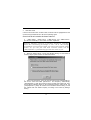
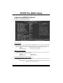
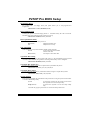
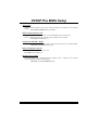
P Prro PP DP TD P44T FCC Statement and Copyright This equipment has been tested and f ound to comply with the limits of a Class B digital device, pursuant to Part 15 of the FCC Rules. These lim its are designed to provide reasonable protection against harmful interf erence in a residential installation. This equipment generates, uses and can radiate radio frequency energy and, if not installed and used in accordance with the instructions, may cause harmf ul interference to radio communications. There is no guarantee that interference will not occur in a particular installation. The v endor makes no representations or warranties with respect to the contents here of and specially disclaims any m i plied warranties of merchantability or fitness for any purpose. Further the v endor reserv es the right to rev ise this publication and to make changes to the contents here of without obligation to notify any party beforehand. Duplication of this publication, in part or in whole is not allowed without first obtaining the v endor’s approval in writing. The content of this user’s is subject to be changed without notice and we will not be responsible f or any mistakes found in this user’s manual. All the brand and product names are trademarks of their respective companies. i C Coonntteennttss ENGLISH .............................................................................................1 P4TDP Pro Features.......................................................................................................................1 Package contents ...........................................................................................................................2 Layout of P4TDP P ro......................................................................................................................2 CPU Installation ...............................................................................................................................3 DDR DIMM Modules: DDR1-2.......................................................................................................4 Jumpers, Head ers, Connectors & Slots ...................................................................................5 ESPAÑOL .......................................................................................... 11 Caracter ísticas del P4TDP Pro ..................................................................................................11 Contenido del Paqu ete................................................................................................................12 Disposición del P4TDP Pro ........................................................................................................12 Instalación de la CPU...................................................................................................................13 Módulos DDR DIMM: DDR1-2....................................................................................................14 Puentes, Cabez ales, Conectores y Ranuras .........................................................................15 DEUTSCH ..........................................................................................21 Merkmal e des P 4TDP Pro ...........................................................................................................21 Verpackungsinhalt ........................................................................................................................22 Layout des P4TDP Pro ................................................................................................................22 Installation der CPU .....................................................................................................................23 DDR-DIMM-Modules: DDR1-2....................................................................................................24 Jumpers, Head ers, Anschlü sse & Slots .................................................................................25 WARPSPEEDER ................................................................................31 Introduction....................................................................................................................................31 S ystem Requirement ...................................................................................................................32 Installation ......................................................................................................................................32 Usage ...............................................................................................................................................34 TROU BLE SHOOTING .......................................................................42 SOLUCIÓN DE PROBLEMAS.............................................................43 PROBLEMLÖSUNG...........................................................................44 ii English P4TDP Pro Features Use Intel 845E/ ICH2 Chipset, ITE I/O- IT8712. Contains on board I/O facilities, which include two serial port, a parallel port, a PS/2 mouse port, a PS/2 key board port, audio ports, USB ports, a game port . Supports the Intel Pentium 4 (Socket 478) processor up to 2.4GHz. Supports Ultra 100/66/33, BMIDE and PIO modes. Supports up to 2 DDR 200/ 266/ Fuzzy 333 MHz dev ices, running at 400 MHz/ 533 Front Side Bus f requency. Supports fiv e 32-bit PCI Bus slots, and one CNR Slot (Ty pe A only ) . ® (If use the onboard CODEC, the CNR slot only support slave card. use H/W Audio, then the CNR slot only support primary card) If Supports USB1.1. Supports USB2.0(optional). Complies with PC ATX f orm f actor specif ications. Supports popular operating systems such as Windows 98, Windows NT, Windows 2000, Windows ME, Windows XP, LINUX and SCO UNIX. DIMM Power Selection by BIOS setup to adjust DDR DIMM v oltage. (Once encounter the DDR DIMM compatible problem, try to adjust the DDR Voltage to f ix the compatible program.) Intel High S/N ratio meets PC 99 requirements. 6CH , applicable for leading motherboard chipsets. Line-in phone-jack share with rear out . Mic-in phone-jack share with Bass and Center. ® AC’97 2.2 compatible. 1 Package contents HDD Cable X 1, FDD Cable X 1, Fully Setup Driv er CD X 1 USB Cable X 2 (Optional) Layout of P4TDP Pro JK BMS1 K /B & Mouse JU SB1 JCFAN1 JK BV1 JATXPW R2 1 JUS BV1 C OM1 JCO M1 DDR 1 DDR 2 Socke t478 Paral le l Port JPRN T1 I /O JCO M2 GAME Po rt MIC- IN LIN E-IN SP-OU T JG AME1 IN TEL 845E 2 JUSB4 JUS BV4 BAT1 JATXP WR1 J1 JD I MMVO LT1 2 1 A GP 1 U SB 2 .0 C hi p ( op ti on al) JA UD IO 1 2 1 PCI 1 JU S B3 JCDI N1 PCI 2 INTEL IC H2 2 JU S B2 Cod ec (op tio na )l JCMO S1 2 PCI 3 1 JUSBV 2_3 PCI 4 H/W A UDI O Chi p ( opt io na l) IDE1 P R IM AR Y ID E C O NN . S EC ONDARY IDE C ONN. PCI 5 FL OPPY DISK C ONN. IDE2 F DD 1 JS FA N1 JW OL1 2 1 1 1 BI O S CNR1 2 JPAN EL1 24 23 CPU Installation CPU 1. Pull the lever sideways away f rom the socket then raise the lever up to 90-degree angle. 2. Locate Pin A in the socket and lock f or the white dot or cut edge in the CPU. Match Pin A with the white dot/cut edge then insert the CPU. 3. Press the lever down. Then Put the f an on the CPU and buckle it and put the f an’s power port into the JCFAN1, then to complete the installation. CPU/ S ystem Fan Headers: JCFAN1/ JS FAN1 12V Gro un d Sense 12 V Gro und Sen se 1 1 JCFAN1 JSFAN1 3 DDR DIMM Modules: DDR1-2 DRAM Access Time: 2.5V Unbuffered DDR 200/266/Fuzzy 333 MHz Ty pe required (x16 does not support). DRAM Ty pe: 64MB/ 128MB/ 256MB/ 512MB/ 1GB DIMM Module (184 pin) DIMM Socket Location DDR Module DDR 1 64MB/128MB/256MB/512MB/1GB *1 DDR 2 64MB/128MB/256MB/512MB/1GB *1 Total Memory Size (MB) Max is 2GB * The list shown above f or DRAM configuration is only f or ref erence. How to install a DIMM Module 1. The DIMM socket has a “ Plastic Safety Tab”, and the DIMM memory module has an “Asymmetrical notch”, so the DIMM memory module can only fit into the slot in one direction. 2. Push the tabs out. Insert the DIMM memory modules into the socket at a 90-degree angle, then push down v ertically so that it will fit into the place. 3. The Mounting Holes and plastic tabs should f it over the edge and hold the DIMM memory modules in place. 4 Jumpers, Headers, Connectors & Slots Hard Disk Connectors: IDE1/ IDE2 The motherboard has a 32-bit Enhanced PCI IDE Controller that provides PIO Mode 0~4, Bus Master, and Ultra DMA / 33/ 66/ 100 f unctionality. It has two HDD connectors IDE1 (primary ) and IDE2 (secondary ). The IDE connectors can connect a master and a slav e drive, so you can connect up to four hard disk driv es. The f irst hard driv e should alway s be connected to IDE1. Floppy Disk Connector: FDD1 The motherboard prov ides a standard f loppy disk connector that supports 360K, 720K, 1.2M, 1.44M and 2.88M f loppy disk ty pes. This connector supports the prov ided f loppy drive ribbon cables. Communication Network Riser S lot: CNR1 The CNR specif ication is an open Industry Standard Architecture, and it def ines a hardware scalable riser card interf ace, which supports audio, network and modem only (slave card only) . (If use the onboard CODEC, the CNR slot only support slave card. If use H/W Audio, then the CNR slot only support primary card) Accelerated Graphics Port S lot: AGP1 Unlike the mouse ports, key board ports and printer ports this motherboard does not hav e built in v ideo facilities and therefore requires a video card f or one of the expansion slots. Your monitor will attach directly to that v ideo card. This motherboard supports video cards f or PCI, and it is also equipped with an Accelerated Graphics Port (AGP). An AGP card will take advantage of AGP technology for improved video efficiency and performance, especially with 3D graphics. Peripheral Component Interconnect Slots: PCI1-5 This motherboard is equipped with 5 standard PCI slots. PCI stands f or Peripheral Component Interconnect, and it is a bus standard f or expansion cards, which has, supplanted the older ISA bus standard in most ports. This PCI slot is designated as 32 bits. 5 Power Connectors: JATXPWR1/ J ATXPWR2 JATXPWR2 (ATX 12V Power Conn.) JATXPWR1 (ATX Main Po wer Con n.) DIMM Po wer S election Connector: JDIMMVOLT1 (Optional) 2 1 JDIMMVOLT (Default ==> 2.5V) Jump Open==> Pin 1-2 on ==> Pin 3-4 on ==> Pin 5-6 on ==> Pin 7-8 on ==> Wake On LAN Header: JWO L1 Ground 5V_SB Wake up 1 WOL1 6 2.5V 2.6V 2.7V 2.8V 2.9V Front US B Header: JUS B2/ JUSB3(Optional) / JUSB4(Optional) 2 1 JUSB2/3/4 JUSB1 (Located in the back panel) USB 1.1 Before Chip using USB 2.0 Chip After using USB 2.0 Chip USB 2.0 Chip Pin1,2 Pin3,4 Pin5,6 Pin7,8 Pin9 Pin10 ==> ==> ==> ==> ==> ==> +5V Data(-) Data(+) Ground KEY NA JUSB2 JUSB3 JUSB4 USB 1.1 Chip X X USB 1.1 Chip USB 1.1 Chip USB 2.0 Chip 5V/ 5 VS B Selection for US B: JUS BV1/2_3/ JUS BV4(Optional) 1 Pin 1-2 on ==> 5V JUSBV1/2_3/4 Pin 2-3 on ==> 5V_SB 5V/ 5 VS B Selection for KB: JKBV1 1 JKBV1 Pin 1-2 on ==> 5V Pin 2-3 on ==> 5V_SB 7 5V/ 5 VS B Selection for US B WAKE-UP: J1(Optional) 1 Pin 1-2 ==> on Pin 2-3 ==> off J1 z JUSB1 and JUSB4 will change to 5V_SB after using USB 2.0 Chip (VT6202) and the 5V/ 5VSB Selection for USB WAKE-UP (J1) will be set in “on” mode. Audio S ubsystem: JAUDIO1/ JCDIN1 2 1 1 JAUDIO1 JC DIN1 ( Front Audio Hea der) ( CD-R OM Audio-I n He ader ) 22 1 Pin 1 3 5 7 9 10 9 J AUDIO1 Pin 2 4 6 8 10 Assignment Mic In Mic Power RT Line Out Reserved LFT Line Out 8 Assignment Ground Audio Power RT Line Out NC LFT Line Out Front Panel Audio Connector/ Jumper Bloc k J umpe r Setting 1 3 5 7 9 2 4 6 1 3 5 7 9 2 4 6 C onfiguration Pin 5 and 6 Pin 9 and 1 0 10 No jum per s installed 10 Au dio lin e o ut sign als are ro uted to th e back p an el au dio lin e o ut con nector. Au dio lin e o ut and m ic in s ig nals are ava ilable f or fro nt p anel au d io co nn ecto rs . Front Panel Connector: JPAN EL1 PWR_LED SLP ON /OFF (+) (+) (-) IR 2 24 1 23 SPK (+) (-) HLE D RST IR SPK ==> Speaker Conn. HLED ==> Hard Driver LED RST ==> Reset Button IR ==> Infrared Conn. SLP ==> Sleep Button PWR_LED ==> Power LED ON/ OFF ==> Power-on Button 9 Clear CMOS Jumper: JCMOS 1 JCMOS1 Assignment Normal Operation (default) 1 Pi n 1-2 on 1 Clear CMOS Data Pi n 2-3 on Back Panel Connectors JKBMS1 JPRNT1 PS/2 M ouse P S/2 Keyboard Game P ort USB Mic In COM COM11 JCOM2 JCOM1 4 Ch ann el Spe akers Sp eaker Ou t JGAME1 Line In/ Mic In Rear Speaker 6 Ch an n el Sp eak ers Spea ker Out 10 Line I n/ Rea r Sp eaker Mic In/ Center & Bass Español Características del P4TDP Pro Usa Chipset Intel 845E/ ICH2, ITE I/O- IT8712. Contiene f acilidades I/O integrados en la placa madre en el que incluy e dos puertos en serie, un puerto paralelo, un puerto para ratón PS/2, un puerto para teclado PS/2, puertos de audio, puertos USB y un puerto de juego . Soporta procesadores Intel Pentium 4 (Socket 478) de hasta 2.4GHz. Soporta Ultra 100/66/33, BMIDE y modos PIO. Soporta hasta 2 dispositivos DDR 200/266/Fuzzy 333 MHz, corriendo a 400 MHz/ 533 MHz frecuencia Front Side Bus. Soporta cinco ranuras PCI 32-bit y una ranura CNR (solamente de Tipo A) . ® (Si usa CODEC integrado en la placa madre, la ranura CNR solamente soporta tarjeta esclava. Si usa H/W Audio, la ranura CNR solamente soporta tarjeta primaria.) Soporta USB1.1. Soporta USB2.0 (opcional). Compatible con las especificaciones del factor de forma de tamaño de PC ATX. Soporta sistemas operativ os populares tales como Windows 98, Windows NT, Windows 2000, Windows ME, Windows XP, LINUX y SCO UNIX. Corriente de Selección DIMM para configuración BIOS utilizado para ajustar voltaje DDR DIMM. (Si se encuentra con un problema compatible al DDR DIMM, trate de ajustar el v oltaje DDR para fijar con el programa compatible.) Compatible con Intel Alto S/N ratio para requerimientos PC 99. ® AC’97 2.2. 11 6CH , aplicable para chipsets de principales placas madres. Entrada de Línea phone-jack compartido con el rear out. Micróf ono phone-jack compartido con Bass y Center. Contenido del Paquete Cable HDD X 1, Cable FDD X 1, Configuración Completa del Driv er CD X1 Cable USB X 2 (Opcional) Disposición del P4TDP Pro JKB MS1 J CFAN1 JKB V1 JATXPWR2 1 JUSB 1 JUSB V1 DD R 1 D DR 2 Par all el Po rt JPR NT1 S o ck et 47 8 CO M1 J COM 1 I/O J C OM 2 GAME P or t M IC-IN LIN E-IN S P-OUT JGAME 1 INTEL 845E 2 J USB4 J USBV4 BAT1 JATXPWR1 J1 J DIM M VOLT1 2 1 AGP 1 US B 2.0 C hip ( opti onal) JAUDI O1 2 1 PC I1 J USB 3 JC DI N1 PC I2 IN TEL I CH 2 2 J USB 2 C odec (op ti on al ) 2 PC I3 J C M OS1 1 JUSB V2_3 PC I4 H/ W AUDI O C hip ( opti onal) I DE1 PRIMARY IDE CONN. SEC ON DA RY I DE CO NN . I DE2 PC I5 F LO PP Y D I SK CO NN . F DD1 BI OS C NR 1 12 J SF AN 1J WOL 1 2 1 1 1 J PANEL 1 24 23 Instalación de la CPU CPU 1. Tire de la palanca del lado del zócalo, luego lev ante la palanca hasta un ángulo de 90 grados. 2. Sitúe el contacto A del zócalo y busque el punto blanco o corte el borde en la CPU. Empareje el contacto A con el punto blanco/ corte del borde, luego inserte la CPU. 3. Presione la palanca para abajo. Ponga el v entilador en la CPU y abróchelo. Luego ponga el puerto de corriente del ventilador en el JCFAN1. Y y a habrá completado su instalación. CPU/ Cabezales del Sistema de Ventilación: JCFAN1/ JS FAN1 12V Tierra Sens e 12V Tierra Sense 1 1 JCFAN1 JSFAN1 13 Módulos DDR DIMM: DDR1-2 DRAM Tiempo de Acceso: 2.5V Unbuffered DDR 200/266/Fuzzy 333 MHz Tipo requerido (no soporta x16) DRAM Tipo: 64MB/ 128MB/ 256MB/ 512MB/ 1GB Módulos DIMM (184 contactos) Localización Módulo DDR del Zócalo DIMM DDR 1 DDR 2 To tal del Tamaño de Memoria (MB) 64MB/128MB/256MB/512MB/1GB *1 64MB/128MB/256MB/512MB/1GB *1 Máximo de 2GB * La lista de arriba para la configuración DRAM es solamente para uso de ref erencia. Cómo instalar un Módulo DIMM 1. El zócalo DIMM tiene una lengüeta plástica de seguridad y el módulo de memoria DIMM tiene una muesca asimétrica, así el módulo de memoria DIMM puede caber solamente en la ranura de una sóla dirección. 2. Tire la lengüeta hacia af uera. Inserte los módulos de memoria DIMM en el zócalo a los 90 grados, luego empuje hacia abajo v erticalmente de modo que encaje en el lugar. 3. Los agujeros de montaje y las lengüetas plásticas deben caber por sobre el borde y sostenga los módulos de memoria DIMM en el lugar. 14 Puentes, Cabezales, Conectores y Ranuras Conectores del Disco Duro: IDE1/ IDE2 La placa madre tiene un controlador de 32-bit PCI IDE que proporciona Modo PIO 0~4, Bus Master, y funcionalidad Ultra DMA / 33/ 66/ 100. Tiene dos conectores HDD IDE1 (primario) y IDE2 (secundario). El conector IDE puede conectar a un master y un drive esclavo, así puede conectar hasta cuatro discos rígidos. El primer disco duro debe estar siempre conectado al IDE1. Conectores para el Disquete: FDD1 La placa madre proporciona un conector estándar del disquete (FDC) que soporta 360K, 720K, 1.2M, 1.44M y 2.88M tipos de disquete. Éste conector utiliza los cables de cinta proporcionados por el disquete. Ranura de la Banda de Suspensión de Comunicación y Red: CNR1 La especificación CNR es una abierta Industria de Arquitectura Estándar, que def ine una tarjeta de interf ace escalable del hardware en el que soporta solamente audio, network y modem (solamente tarjeta esclava). (Si usa CODEC integrado en la placa madre, la ranura CNR solamente soporta tarjeta esclava. Si usa H/W Audio, la ranura CNR solamente soporta tarjeta primaria.) Accelerated Graphics Port S lot: AGP1 Su monitor se fijará directamente a la tarjeta de video. Ésta placa madre soporta tarjetas de v ideo para ranuras PCI, y también está equipado con un Puerto Acelerado para Gráficos. Ésta tarjeta AGP tomará v entaja de la tecnología del AGP para el mejoramiento de la ef iciencia y f uncionamiento del v ideo, especialmente con gráf icos 3D. Ranura de Interconexión del Componente Periférico: PCI1-5 Ésta placa madre está equipada con 5 ranuras estándar PCI. PCI es la sigla para Interconexión del Componente Periférico, y es un bus estándar para tarjetas de expansión en el que suplanta a la antigua bus estándar ISA, en su may oría de las partes. Ésta ranura PCI está diseñado con 32 bits 15 Conectores de Corriente: JATXPWR1/ J ATXPWR2 JATXPWR2 (ATX 12V Conector de Corriente) JATXPWR1 (ATX Co nector de Co rrien te Prin cipal) Conector de Selección de la Corriente DIMM: JDIMMVOLT1 (Opcional) 2 1 JDIMMVOLT (Default ==> 2.5V) Puente Abierto==> 2.5V Contacto 1-2 on ==> 2.6V Contacto 3-4 on ==> 2.7V Contacto 5-6 on ==> 2.8V Contacto 7-8 on ==> 2.9V Cabezal Wake On LAN: J WOL1 Tierra 5V_SB Wake up 1 WOL1 16 Cabezal Frontal US B: JUS B2/ JUS B3(Opcional)/ JUS B4(Opcional) 2 1 JUSB2/3/4 Co ntacto1 ,2 Co ntacto3 ,4 Co ntacto5 ,6 Co ntacto7 ,8 Co ntacto9 Co ntacto1 0 JUSB1 (Ubicado en el panel trasero) USB 1.1 Antes de Chip usar Chip USB 2.0 USB 2.0 Luego de Chip usar Chip USB 2.0 ==> ==> ==> ==> ==> == > +5 V Dato(-) Dato(+) Tierra KEY NA JUSB2 JUSB3 JUSB4 USB 1.1 Chip X X USB 1.1 Chip USB 1.1 Chip USB 2.0 Chip 5V/ 5 VS B Selección para US B: JUS BV1/2_3 / JUS BV4(Opcional) 1 JUSBV1/2_3/4 5V/ 5 VS B Selección para KB: JKBV1 Contacto 1-2 on ==> 5V Contacto 2-3 on ==> 5V_SB 1 JKBV1 17 Contacto 1-2 on ==> 5V Contacto 2-3 on ==> 5V_SB 5V/ 5 VS B Selección para US B WAKE-UP: J1 (Opcional) 1 Contacto 1-2 ==> on Contacto 2-3 ==> off J1 z JUSB1 y JUSB4 cambiará a 5V/5VSB luego de usar el Chip USB 2.0 (VT6202) y el la función 5V/5VSB Selección para USB WAKE-UP (J1) se f ijará al modo “on”. Subsistema de Audio: JAUDIO1/ JCDIN1 2 1 1 JCDIN1 (Cabezal de En trada d e Aud io CD-ROM) JAUDIO1 (Cab ezal Fron tal de Au di o) 22 1 Contactos 1 3 5 7 9 10 9 JAUDIO1 Asignacion Contactos Entrada del MIC 2 Corriente del MIC 4 RT Salida de Linea 6 Reservado 8 LFT Salida de Linea 10 18 Asignacion Tierra Corriente de Audio RT Salida de Linea Key LFT Salida de Linea C onector del Pane l Frontal de Audio/ Jumper Block J umpe r Setting 1 3 5 7 9 2 4 6 1 3 5 7 9 2 4 6 C onfiguracion Co ntacto 5 & 6 Co ntacto 9 & 1 0 La se ~nal d e s alid a d e linea del Au dio enc am ina al co nector d e la salid a d e linea del Au dio ub icad o en el p anel tras ero . 10 No jum per s installed 10 La se ~nal d e s alid a d e linea del Au dio y la ~ d el en trad a d el m ic es ta n disp on ib les s enal des de el co necto r d e A udio d el pan el fro ntal. Conector del Panel Frontal: JPANEL1 PWR_ LED SLP (+) (+) (-) ON/OFF IR 2 24 1 23 SPK (+) (-) HLED RST IR SPK ==> Conector de Altavoz HLED ==> LED del Disco Duro RST ==> Boton de Reinicio IR ==> Conector Infrarojo SLP ==> Boton de Suspension PWR_LED ==> Corriente LED ON/ OFF ==> Boton de Encendido 19 Puente de Borrar CMOS : JCMOS 1 Asignacion JCMOS1 Operacion Normal (Default) 1 Contact o 1-2 on 1 Borrar Datos CMOS Contacto 2-3 on Conectores del Panel Trasero JKBMS1 JPRNT1 Raton PS/2 JGAM E1 Par alelo Puerto de Juego JUSB1 Teclado PS/2 USB COM1 COM2 JCOM1 J COM2 Altavo z d e 4 Can ale s Sal ida d el Alta voz Entrad a de Entrada Linea/ de l Mic Rear Spea ker Salida del Altavo z En trad a En trada de Linea d el MIC Altavo z de 6 Can ales Sa lida del Altavoz 20 Entrad a d e Line a/ Rear Spea ker Entrad a del Mic/ Center & Bass Deutsch Merkmale des P4TDP Pro Benutzt Intel 845E/ ICH2 Chipsatz, ITE I/O- IT8712. Onboard I/O Geräte umfassen: zwei serielle Schnittstelle, eine parallele Schnittstelle, , eine PS/2-Mausschnittstelle, eine PS/2-Tastaturschnittstelle, Audio-Schnittstellen, USB-Schnittstellen, und ein Gameport. Unterstützung für den Prozessor Intel Pentium 4 (Socket 478) bis zu 2.4GHz. Unterstützung für Ultra 100/66/33, BMIDE- und PIO-Modus. Unterstützung bis zu zwei DDR 200/ 266/Fuzzy 333 MHz Geräte, FSB mit 400 / 533 MHz. Unterstützung für fünf 32-bit PCI-Bus-Slots, und ein CNR-Slot ( nur Typ A) . ® (Falls man ein Onboard-Codec verwendet, unterstützt das CNR-Slot nur die Slave-Karte. Falls man ein Onboard-H/W-Audio benutzt, unterstützt dann das CNR-Slot nur die primäre Karte . ) Unterstützung für USB1.1. Unterstützung für USB2.0(optional). Entspricht den PC ATX Formf actor-Spezif ki ation. Unterstützung für die am meisten v erbreiteten Betriebsysteme wie Windows 2000, Windows ME, Windows XP, LINUX and SCO UNIX. Die DDR-DIMM-Spannung wird durch “Bios-Setup”(Auswahl f ür DIMM Stromversorgung) eingestellt. (Wenn Sie die kompatible Probleme v on DDR-DIMM lösen wollen , versuchen Sie bitte, die DDR-Spannung durch “Bios-Setup” einzustellen.) Intel® AC’97 2.2 kompatible. High S/N ratio entspricht den Anfordungen von PC 99. 6-Kanal -Audio gilt f ür f ührende Motherboard-Chipsätze. Line-in Phone-Buchse ist geteilt mit “Rear-Out”. 21 Mic-in Phone-Buchse ist geteilt mit “Bass & Center”. Verpackungsinhalt HDD-Kable X 1, FDD-Kable X 1, Treiber-CD f ür Installation X 1 USB-Kable X 2 (optional) Layout des P4TDP Pro JKBMS1 K/B & Mou se JUSB1 JCFAN1 JKBV1 JAT XPWR2 1 JU SBV1 DDR 1 DDR 2 JP RNT1 So ck e t 4 7 8 Pa ra llel Port CO M1 JCOM1 I /O JGAME1 GAME Por t MIC-IN LIN E-IN SP-O UT JCOM2 INTEL 845E 2 JUSB4 JUS BV4 BAT1 JATXP WR1 J1 JDI MMVO LT 1 2 1 AGP 1 U SB 2. 0 Chip ( op tio nal) JAUDI O1 2 1 P CI1 JUSB3 JCDI N1 P CI2 IN TEL ICH2 2 JUS B2 Cod ec (o ptio na )l 2 JCMOS 1 P CI3 1 JUS BV2 _3 P CI4 H/W A UDI O Chip ( op tio nal) P CI5 I DE1 PRIMA RY ID E CO NN. SEC O N DA RY ID E C O NN . IDE2 FLO PPY D ISK C O NN . F DD 1 BI OS CNR1 22 JS FAN 1 JWOL 1 2 1 1 1 JPANE L 1 24 23 Installation der CPU CPU 1. Ziehen Sie den Hebel seitwärts v on der Sockel und neigen Sie ihn um 90-Grad nach oben. 2. Suchen Sie Pin A im Sockel und den weißen Punkt oder die Abschnittkante in der CPU. Passen Sie Pin A mit dem weißen Punkt/der Abschnittkante zusammen und legen Sie danach die CPU ein. 3. Drücken Sie den Hebel nach unten. Bef estigen Sie danach den Lüfter auf die CPU und schließen Sie die Stromschnittstelle des Lüfters an JCFAN1 an und beenden Sie die Installation. CPU/ S ystem Fan Headers: JCFAN1/ JS FAN1 GND 12 V Sen sor GND 1 12V Senso r 1 JCFAN1 JSFAN1 23 DDR-DIMM-Modules: DDR1-2 DRAM Zugriffszeit: 2.5V unbuffered DDR 200/266/Fuzzy 333 MHz Ty pe erf ordert . (x16 hat keine Unterstützung) DRAM Ty pen: 64MB/ 128MB/ 256MB/ 512MB/ 1GB DIMM-Module (184 pin) DIMM-Sockel DDR-Module Speichergröße (MB) Standort DDR 1 64MB/128MB/256MB/512MB/1GB *1 DDR 2 64MB/128MB/256MB/512MB/1GB *1 maximal si t 2GB * Die obere Liste f ür DRAM-Konf iguration ist nur als Referenz gezeigt. Installation von DIMM-Modulen 1. Es gibt eine Plastikklammer an beiden Enden der DIMM-Slot, und eine Passkerbe in der Mitte des Moduals. Deswegen passt das Dimm-Modual nur in einer Richtung. Pl asti kk lammer 2. Ziehen Sie die Plastikklammer aus. Setzen Sie das DIMM-Modual im 90-Grad-Winkel in den DIMM-Steckplatz und drücken es nach unten. 3. Schließen Sie die Plastikklammer, um das DiMM-Modul zu v erriegeln. 24 Passke rb e Jumpers, Headers, Anschlüsse & Slots Festplattenanschlüsse: IDE1/ IDE2 Das Mainboard hat einen 32-Bit Enhanced PCI IDE-Controller, der die Modi PIO0~4, Bus Master sowie die Ultra DMA/33/66/100 Funktion zur Verfügung stellt. Dieser ist mit zwei HDD-Anschlüssen versehen IDE1 (primär) und IDE2 (sekundär). Die IDE-Anschlüsse können eine Master- und eine Slav e-Festplatte v erbinden, so dass bis zu 4 Festplatten angeschlossen werden können. Die erste Festplatte sollte immer an IDE1 angeschlossen werden. Diskettenanschluss: FDD1 Das Motherboard enthält einen standardmäßigen Diskettenanschluss, der 360K-, 720K-, 1.2M-, 1.44M- und 2.88M-Disketten unterstützt. Dieser Anschluss unterstützt die mitgelieferte Bandkabel des Diskettenlauf werks. Communication Network Riser S lot: CNR1 Die CNR-Spezif ikation erklärt sich als eine “ offene Industrie- StandardArchitekltur “ und sie wird als ein skalierbares Riser-Karte-Interface von Hardware def iniert, das nur Audio, Netzwerk und Modem unterstützt. (Falls man ein Onboard-Codec verwendet, unterstützt das CNR-Slot nur die Slave-Karte. Falls man ein Onboard-H/W-Audio benutzt, unterstützt dann das CNR-Slot nur die primäre Karte.) Accelerated Graphics Port S lot: AGP1 Es ist ungleich mit Maus-, Tastatur- und Print-Ports, dass dieses Motherboard kein Onboard Video-Gerät hat. Deshalb verlangt das Motherboard eine Video-Karte für Ausweitung-Slots. Ihr Monitor wird direkt an die Videokarte angebracht. Dieses Motherboard unterstützt Video-Karten für PCI-Slots und ISA-Slots, aber es ist auch mit einem “Accelerated Graphics Port“ eingerichtet . Mit den AGP-Karten kann man die Wirksamkeit und Leistung v on Viedosignalen v erbessern.(3D-Grafiken f unktioniert noch besser) Peripheral Component Interconnect Slots: PCI1-5 Dieses Motherboard ist mit f ünf standardmäßigen PCI-Slots ausgestattet. PCI steht f ür Peripheral Component Interconnect und bezieht sich auf einem Busstandard f ür Erweiterungskarten, der den älteren ISA-Busstandard in den meisten Schnittstellen ersetzt hat. Dieser PCI-Slot ist für 32 bits vorgesehen. 25 S tromversorgungsanschlüsse: JATXPWR1/ J AT XPWR2 JATXPWR2 (ATX 12V strom anschl.) JATX PW R1 (ATX Netzst rom anschl .) Anschluss für Auswahl von DIMM S tromversorgung: JDIMMVOLT1(o ptional) 2 1 Jumper offen ==> 2.5V Pin 1-2 geschlossen ==> 2.6V Pin 3-4 geschlossen ==> 2.7V Pin 5-6 geschlossen ==> 2.8V Pin 7-8 geschlossen ==> 2.9V JDIMMVOLT (Default = => 2.5V) Wake On LAN Header: JWO L1 GND 5V_SB Wake- Up 1 WOL1 26 Front US B Header: JUS B2/ JUSB3(optional) / JUSB4(optional) Pin1,2 Pin3,4 Pin5,6 Pin7,8 Pin9 Pin10 2 1 JUSB2/3/4 Kein USB 2.0-Chip Zunahme v on USB 2.0-Chip ==> ==> ==> ==> ==> ==> +5V Data(-) Data(+) GND KEY NA JUSB1 (auf der Ruckwand) USB 1.1-Chip JUSB2 JUSB3 JUSB4 USB 1.1-Chip X X USB 2.0-Chip USB 1.1-Chip USB 1.1-Chip USB 2.0-Chip 5V/ 5 VS B Auswahl für US B: JUS BV1/2_3 / JUS BV4(optional) 1 JUSBV1/2_3/4 Pin 1-2 geschlossen ==> 5V Pin 2-3 geschlossen ==> 5V_SB 5V/ 5 VS B Auswahl für KB: JKBV1 1 JKBV1 Pin 1-2 geschlossen ==> 5V Pin 2-3 geschlossen ==> 5V_SB 27 5V/ 5 VS B Auswahl für US B-Wake-UP: J1(optional) 1 Pin 1-2 geshlossen ==> aktiviert J1 z Pin 2-3 geschl ossen ==> deaktiviert Nachdem man einUSB2.0-Chip benutzt und J1 auch in “aktiviert” Mode festgelegt wird, werden JUSB1/4(weiß) zu 5V_SB geändert. Audio S ubsystem: JAUDIO1/ JCDIN1 2 1 1 JAUDIO1 JC DIN1 ( Front Audio Hea der) ( CD-R OM Audio-I n He ader ) 22 1 Pin 1 3 5 7 9 10 9 JF_ AU DIO Pin 2 4 6 8 10 Beschreibung Mic In Mic Power RT Line Out Reserved LFT Line Out 28 Beschreibung GND Audio Power RT Line Out Key LFT Line Out Au dio-A ns chl s s e f r d ie Vord ers eite/ J umper- Bloc k Jum pe r-Ei nste llen 1 3 5 7 9 2 4 6 1 3 5 7 9 2 4 6 Pi n 5 u nd 6 Pi n 9 u nd 10 Ko n fig ura tio n Audi o-Ausg an g-Si ngal s werd en zu der Audi oAusg an g-Anschl uss an der R uckwand gel ei tet . 10 10 K e in J ump er i nst a ll ie re n Audi o-Aus gang und Mi c-In -Si ngals s ind verf ugb ar f ur Audi o-Anschl us se an der Vo rders eit e. Anschlüsse auf der Vorderseite: JPANEL1 SLP PWR_LED (+) (+) (-) ON/OFF IR 24 2 1 23 SPK (+) (-) HLED RST IR SPK ==> Lautsprecheranschl. HLED ==> Festplattenanzeige RST ==> Reset-Taste IR ==> Infrarotanschl. SLP ==> Sleep-Taste PWR_LED ==> Stromanzeige EIN/AUS ==> EIN /Ausschalttaste 29 Jumper zum Löschen des CMOS: JCMOS1 JCMOS1 Beschreibung 1 Normale Operation (Default) Pin 1-2 geschlosssen 1 Pin 2-3 geschlossen CMOS-Daten loschen Anschlüsse auf der Rückwand: JKBMS1 JPRNT1 PS/2Mau s PS/2Tastatur JGAME1 Gameport USB COM1 COM1 JCOM2 JCOM1 6-Kana l-Lau tspre ch er Speaker-Out Line -I n/ Mic-In Rea r-Spe ake r Speaker-Out 30 Line -I n/ Rea r-Spea ke r Mic-I n/ Center & Bass WarpSpeeder Introduction [ WarpSpeeder™ ], a new powerf ul control utility, features three user-friendly f unctions including Overclock Manager, Overvoltage Manager, and Hardware Monitor. With the Overclock Manager, users can easily adjust the frequency they pref er or they can get the best CPU perf ormance with just one click. The Ov ervoltage Manager, on the other hand, helps to power up CPU core v oltage and Memory v oltage. The cool Hardware Monitor smartly indicates the temperatures, voltage and CPU f an speed as well as the chipset information. Also, in the About panel, y ou can get detail descriptions about BIOS model and chipsets. In addition, the frequency status of CPU, memory, AGP and PCI along with the CPU speed are synchronically shown on our main panel. Moreov er, to protect users' computer systems if the setting is not appropriate when testing and results in system f ail or hang, [ WarpSpeeder™ ] technology assures the system stability by automatically rebooting the computer and then restart to a speed that is either the original system speed or a suitable one. 31 System Requirement OS Support: Windows 98 SE, Windows Me, Windows 2000, Windows XP DirectX: DirectX 8.1 or above. (The Windows XP operating system includes DirectX 8.1. If y ou use Windows XP, you do not need to install DirectX 8.1.) Installation 1. Execute the setup execution f ile, and then the following dialog will pop up. Please click “Next” button and follow the default procedure to install. 32 2. When you see the f ollowing dialog in setup procedure, it means setup is completed. If the “Launch the WarpSpeeder Tray Utility ” checkbox is checked, the Tray Icon utility and [ WarpSpeeder™ ] utility will be automatically and immediately launched after y ou click “Finish” button. 33 Usage The following figures are just only for reference, the screen printed in this usr manual will change according to your motherboard on hand. [ WarpSpeeder™ ] includes 1 tray icon and 5 panels: 1. Tray Icon: Whenev er the Tray Icon utility is launched, it will display a little tray icon on the right side of Windows Taskbar. This utility is responsible for conveniently invoking [ WarpSpeeder™ ] Utility. Y ou can use the mouse by clicking the left button in order to invoke [ WarpSpeeder™ ] directly f rom the little tray icon or y ou can right-click the little tray icon to pop up a popup menu as following figure. The “Launch Utility” item in the popup menu has the same function as mouse left-click on tray icon and “Exit” item will close Tray Icon utility if selected. 34 2. Main Panel If you click the tray icon, [ WarpSpeeder™ ] utility will be inv oked. Please ref er do the following f igure; the utility’s f irst window you will see is Main Panel. Main Panel contains features as follows: a. Display the CPU Speed, CPU external clock, Memory clock, AGP clock, and PCI clock inf ormation. b. Contains About, Voltage, Overclock, and Hardware Monitor Buttons f or inv oking respective panels. c. With a user-f riendly Status Animation, it can represent 3 overclock percentage stages: Man walking => ov erclock percentage from 100% ~ 110 % Panther running => overclock percentage from 110% ~ 120% Car racing => ov erclock percentage f rom 120% ~ above 35 3. Voltage Panel Click the Voltage button in Main Panel, the button will be highlighted and the Voltage Panel will slide out to up as the f ollowing figure. In this panel, you can decide to increase CPU core voltage and Memory voltage or not. The def ault setting is “No”. If y ou want to get the best perf ormance of overclocking, we recommendy ou click the option “Y es”. 36 4. Overclock Panel Click the Overclock button in Main Panel, the button will be highlighted and the Overclock Panel will slide out to left as the following f igure. Overclock Panel contains the these features: a. “–3MHz button”, “-1MHz button”, “+1MHz button”, and “+3MHz button”: prov ide user the ability to do real-time overclock adjustment. Warning: Manually overclock is potentially dangerous, especially w hen the overclocking percentage is over 110 %. We strongly recommend you verify every speed you overclock by click the Verify button. Or, you can just click Auto overclock button and let [ WarpSpeeder™ ] automatically gets the best result for you. b. “Recovery Dialog button”: Pop up the following dialog. Let user select a restoring way if system need to do a fail-safe reboot. c. “Auto-overclock button”: User can click this button and [ WarpSpeeder™ ] will set the best and stable performance and frequency automatically. [ WarpSpeeder™ ] utility will execute a series of testing until system fail. Then sy stem will do f ail-saf e reboot by using Watchdog f unction. After reboot, the [ WarpSpeeder™ ] utility will restore to the hardware def ault setting or load the verified best and stable f requency according to the Recov ery Dialog’s setting. 37 d. “Verify button”: User can click this button and [ WarpSpeeder™ ] will proceed a testing for current f requency. If the testing is ok, then the current f requency will be saved into system registry. If the testing fail, sy stem will do a fail-safe rebooting. After reboot, the [ WarpSpeeder™ ] utility will restore to the hardware default setting or load the verif ied best and stable f requency according to the Recovery Dialog’s setting. Note: Because the testing programs, invoked in Auto-overclock and Verify, include DirectDraw , Direct3D and DirectShow tests, the DirectX 8.1 or new er runtime library is required. And please make sure your display card’s color depth is High color (16 bit) or True color( 24/32 bit ) that is required for Direct3D rendering. 38 5. Hardware Monitor Panel Click the Hardware Monitor button in Main Panel, the button will be highlighted and the Hardware Monitor panel will slide out to left as the following f igure. In this panel, y ou can get the real-time status inf ormation of y our system. The information will be refreshed ev ery 1 second. 6. About Panel Click the About button in Main Panel, the button will be highlighted and the About Panel will slide out to up as thef ollowing figure. In this panel, you can get model name and detail inf ormation in hints of all the chipset that are related to overclocking. Y ou can also get the mainboard’s BIOS model and the Version number of [ WarpSpeeder™ ] utility. 39 40 Note: Because the overclock, overvoltage, and hardw are monitor features are controlled by several separate chipset, [ WarpSpeeder™ ] divide these features to separate panels. If one chipset is not on board, the correlative button in Main panel w ill be disabled, but will not interfere other panels’ functions. This property can make [ WarpSpeeder™ ] utility more robust. 41 Trouble Shooting PROBABLE SOLUTION No power to the system at all Power light don’t * Make sure power cable is securely plugged in illuminate, fan inside power supply does not turn * Replace cable on. Indicator light on keyboard does not turn on * Contact technical support PROBABLE SOLUTION System inoperative. Keyboard lights are on, * Using even pressure on both ends of the power indicator lights are lit, hard drive is DIMM, press down firmly until the module snaps into place. spinning. PROBABLE SOLUTION System does not boot from hard disk drive, can * Check cable running from disk to disk be booted from CD-ROM drive. controller board. Make sure both ends are securely plugged in; check the drive type in the standard CMOS setup. * Backing up the hard drive is extremely important. All hard disks are capable o breaking down at any time. PROBABLE SOLUTION System only boots from CD-ROM. Hard disk can * Back up data and applications files. Reforma be read and applications can be used but the hard drive. Re-install applications and data using backup disks. booting from hard disk is impossible. PROBABLE SOLUTION Screen message says “Invalid Configuration” or * Review system’s equipment . Make sure “CMOS Failure.” correct information is in setup. PROBABLE SOLUTION Cannot boot system after installing second hard * Set master/slave jumpers correctly. drive. * Run SET UP program and select correct drive types. Call drive manufacturers for compatibility with other drives. 42 Solución de Problemas CAUSA PROB ABLE SOLUCIÓN No hay corriente en el sistema. La luz de * corriente no ilumina, ventilador dentro de la fuente de alimentación apagada. Indicador de * luz del teclado apagado. * CAUSA PROB ABLE Asegúrese que el cable de transmisión esté seguramente enchufado. Reemplace el cable. Contacte ayuda técnica. SOLUCIÓN Sistema inoperativo. Luz del teclado encendido, * Presione los dos extremos del DIMM, presione luz de indicador de corriente iluminado, disco para abajo firmemente hasta que el módulo rígido está girando. encaje en el lugar. CAUSA PROB ABLE SOLUCIÓN Sistema no arranca desde el disco rígido, puede * Controle el cable de ejecución desde el disco ser arrancado desde el CD-ROM drive. hasta el disco del controlador. Asegúrese de que ambos lados estén enchufados con seguridad; controle el tipo de disco en la configuración estándar CMOS. * Copiando el disco rígido es extremadamente importante. T odos los discos rígidos son capaces de dañarse en cualquier momento. CAUSA PROB ABLE SOLUCIÓN Sistema solamente arranca desde el CD-ROM. * Copie datos y documentos de aplicación Disco rígido puede leer y aplicaciones pueden Vuelva a formatear el disco rígido. Vuelva a ser usados pero el arranque desde el disco instalar las aplicaciones y datos usando e rígido es imposible. disco de copiado. CAUSA PROB ABLE SOLUCIÓN Mensaje de pantalla ”Invalid Configuration” o * Revise el equipo del sistema. Asegúrese de que la información configurada sea correcta. “CMOS Failure.” CAUSA PROB ABLE SOLUCIÓN No puede arrancar después de instalar el * Fije correctamente el puente master/esclavo. segundo disco rígido. * Ejecute el programa SET UP y seleccione e tipo de disco correcto. Llame a una manufacturación del disco para compatibilidad con otros discos. 43 Problemlösung MÖGLICHE URSACHE LÖSUNG Das System hat keine Spannungsversorgung. * Versichern Sie sic h, dass das Stromkabel richtig Die Stromanzeige leuchtet nicht, der Lüfter im angebracht ist Inneren der Stromversorgung wird nicht * Ersetzen Sie das Stromkabel eingeschaltet. T astatu rleuchten sind nicht an. * Wenden Sie sich an Ihre Kundendienststelle MÖGLICHE URSACHE LÖSUNG Das System funktioniert nicht. Die * Drücken Sie das D I MM- Modul bei gleichem T astaturleuchten sind an, die Stromanzeige Druck an beide Seiten, bis es einrastet. leuchtet, die Festplatte dreht sich. MÖGLICHE URSACHE LÖSUNG Das System wird von der Festplatte nicht * Überprüfen Sie das Kabel zwischen Festplatte hochgefahren, vom CD-ROM-T reiber aber ja. und Festplatten-Controller. Versichern Sie sich, dass beide Enden richtig angebrach sind; überprüfen Sie den Laufwerktyp in der standardmäßigen CMOS-Einrichtung. * Ein Backup der Festplatte ist sehr wichtig. Alle Festplatten können irgendwann beschädig werden. MÖGLICHE URSACHE LÖSUNG Das System wird nur von der CD-RO M * Machen Sie eine Sicherungskopie von allen hochgefahren. Die Festplatte wird gelesen und Daten und Anwendungsdateien. Formatieren die Anwendungen sind funktionsfähig, aber es Sie die Festplatte und reinstallieren Sie die ist nicht möglich, das System von der Festplatte Anwendungen und Daten mit Hilfe von Backup-Disks. zu starten. MÖGLICHE URSACHE LÖSUNG Auf dem Bildschirm erscheint die Meldung * Überprüfen Sie die Systemkomponenten und versichern Sie sich, das diese richtig “Ungültige Konfiguration” oder “CMOS Fehler.” eingerichtet sind. MÖGLICHE URSACHE LÖSUNG Das System kann nach der Installation einer * Setzen Sie die Master/Slave-Jumper richtig ein. zweiten Festplatte nicht hochgefahren werden. * Führen Sie das SET UP-Programm aus und wählen Sie die richtigen Laufwerktypen. Wenden Sie sich an den Laufwerkhersteller, um die Kompatibilität mit anderen Laufwerken zu überprüfen. 44 01/28/2003 45 P4TDP Pro BIOS Setup BIOS Setup........................................................................................1 1 Main Menu..................................................................................................... 3 2 Standard CMOS Features .............................................................................. 6 3 Advanced BIOS Features............................................................................... 9 4 Advanced Chipset Features.......................................................................... 12 5 Integrated Peripherals .................................................................................. 15 6 Power Management Setup ........................................................................... 19 7 PnP/PCI Configurations ............................................................................... 23 8 PC Health Status .......................................................................................... 26 9 Frequency Control ....................................................................................... 28 i P4TDP Pro BIOS Setup BIOS Setup Introduction This manual discussed Award™ Setup program built into the ROM BIOS. The Setup program allows users to modify the basic system configuration. This special information is then stored in battery-backed RAM so that it retains the Setup information when the power is turned off. The Award BIOS™ installed in your computer system’s ROM (Read Only Memory) is a custom version of an industry standard BIOS. This means that it supports Intel Pentium ® 4 processor input/output system. The BIOS provides critical low-level support for standard devices such as disk drives and serial and parallel ports. Adding important has customized the Award BIOS™, but nonstandard, features such as virus and password protection as well as special support for detailed fine-tuning of the chipset controlling the entire system. The rest of this manual is intended to guide you through the process of configuring your system using Setup. Plug and Play Support These AWARD BIOS supports the Plug and Play Version 1.0A specification. ESCD (Extended System Configuration Data) write is supported. EPA Green PC Support This AWARD BIOS supports Version 1.03 of the EPA Green PC specification. APM Support These AWARD BIOS supports Version 1.1&1.2 of the Advanced Power Management (APM) specification. Power management features are implemented via the System Management Interrupt (SMI). Sleep and Suspend power management modes are supported. This AWARD BIOS can manage power to the hard disk drives and video monitors . ACPI Support Award ACPI BIOS support Version 1.0 of Advanced Configuration and Power interface specification (ACPI). It provides ASL code for power management and device configuration capabilities as defined in the ACPI specification, developed by Microsoft, Intel and Toshiba. 1 P4TDP Pro BIOS Setup PCI Bus Support This AWARD BIOS also supports Version 2.1 of the Intel PCI (Peripheral Component Interconnect) local bus specification. DRAM Support DDR DRAM (Double Data Rate Synchronous DRAM) are supported. Supported CPUs This AWARD BIOS supports the Intel Pentium ® 4 CPU. Using Setup In general, you use the arrow keys to highlight items, press <Enter> to select, use the <PgUp> and <PgDn> keys to change entries, press <F1> for help and press <Esc> to quit. The following table provides more detail about how to navigate in the Setup program by using the keyboard. Keystroke Up arrow Down arrow Left arrow Right arrow Move Enter PgUp key PgDn key + Key - Key Esc key F1 key F5 key F6 key F7 key F10 key Function Move to previous item Move to next item Move to the item on the left (menu bar) Move to the item on the right (menu bar) Move to the item you desired Increase the numeric value or make changes Decrease the numeric value or make changes Increase the numeric value or make changes Decrease the numeric value or make changes Main Menu – Quit and not save changes into CMOS Status Page Setup Menu and Option Page Setup Menu – E xit Current page and return to Main Menu General help on Setup navigation keys Load previous values from CMOS Load the fail-safe defaults from B IOS default table Load the optimized defaults Save all the CMOS changes and exit 2 P4TDP Pro BIOS Setup 1 Main Menu Once you enter Award BIOS™ CMOS Setup Utility, the Main Menu will appear on the screen. The Main Menu allows you to select from several setup functions. Use the arrow keys to select among the items and press <Enter> to accept and enter the sub-menu. !! WARNING !! The information about BIOS defaults on manual (Figure 1,2,3,4,5,6,7,8,9) is just for reference, please refer to the BIOS installed on board, for update information. Figure 1. Main Menu Standard CMOS Features This submenu contains industry standard configurable options. Advanced BIOS Features This submenu allows you to configure enhanced features of the BIOS. Advanced Chipset Features This submenu allows you to configure special chipset features. 3 P4TDP Pro BIOS Setup Integrated Peripherals This submenu allows you to configure certain IDE hard drive options and Programmed Input/ Output features. Power Management Setup This submenu allows you to configure the power management features. PnP/PCI Configurations This submenu allows you to configure certain “Plug and Play” and PCI options. PC Health Status This submenu allows you to monitor the hardware of your system. Frequency Control This submenu allows you to change CPU Vcore Voltage and CPU/PCI clock. (However, this function is strongly recommended not to use. Not properly change the voltage and clock may cause CPU or M/B damage!) Load Optimized Defaults This selection allows you to reload the BIOS when the system is having problems particularly with the boot sequence. These configurations are factory settings optimized for this system. A confirmation message will be displayed before defaults are set. Set Supervisor Password Setting the supervisor password will prohibit everyone except the supervisor from making changes using the CMOS Setup Utility. You will be prompted with to enter a password. Set User Password If the Supervisor Password is not set, then the User Password will function in the same way as the Supervisor Password. If the Supervisor Password is set and the User Password is set, the “User” will only be able to view configurations but will not be able to change them. 4 P4TDP Pro BIOS Setup Save & Exit Setup Save all configuration changes to CMOS(memory) and exit setup. Confirmation message will be displayed before proceeding. Exit Without Saving Abandon all changes made during the current session and exit setup. Confirmation message will be displayed before proceeding. Upgrade BIOS This submenu allows you to upgrade bios. 5 P4TDP Pro BIOS Setup 2 Standard CMOS Features The items in Standard CMOS Setup Menu are divided into 10 categories. Each category includes no, one or more than one setup items. Use the arrow keys to highlight the item and then use the<PgUp> or <PgDn> keys to select the value you want in each item. Figure 2. Standard CMOS Setup 6 P4TDP Pro BIOS Setup Main Menu Selections This table shows the selections that you can make on the Main Menu. Item Options Date mm : dd : yy Set the system date. Note that the ‘Day’ automatically changes when you set the date. Time hh : mm : ss Set the clock. IDE Primary Master Options are in its sub menu. Press <Enter> to enter the sub menu of detailed options IDE Primary Slave Options are in its sub menu. Press <Enter> to enter the sub menu of detailed options. IDE Secondary Master Options are in its sub menu. Press <Enter> to enter the sub menu of detailed options. IDE Secondary Slave Options are in its sub menu. Press <Enter> to enter the sub menu of detailed options. 360K, 5.25 in Select the type of floppy disk drive installed in your system. Drive A 1.2M, 5.25 in 720K, 3.5 in Drive B Description system internal 1.44M, 3.5 in 2.88M, 3.5 in None Video EGA/VGA CGA 40 CGA 80 MONO 7 Select the default device. video P4TDP Pro BIOS Setup Item Halt On Options Description All Errors Select the situation in which No Errors you want the BIOS to stop All, but Keyboard All, but Diskette the POST process and notify you. All, but Disk/ Key Base Memory N/A Displays the amount of conventional memory detected during boot up. Extended Memory N/A Displays the amount of extended memory detected during boot up. Total Memory N/A Displays the total memory available in the system. 8 P4TDP Pro BIOS Setup 3 Advanced BIOS Features Figure 3. Advanced BIOS Setup Virus Warning This option allows you to choose the Virus Warning feature that is used to protect the IDE Hard Disk boot sector. If this function is enabled and an attempt is made to write to the boot sector, BIOS will display a warning message on the screen and sound an alarm beep. Enabled Virus protection is activated. Disabled (default) Virus protection is disabled. Quick Power On Self Test Enabling this option will cause an abridged version of the Power On Self-Test (POST) to execute after you power up the computer. Disabled Normal POST. Enabled (default) Enable quick POST. First /Second/Third/ Boot Other Device These BIOS attempt to load the operating system from the devices in the sequence selected in these items. The Choices: Floppy, LS120, HDD-0, SCSI, CDROM, HDD-1, HDD-2, HDD-3, ZIP100, LAN, Disabled, Enabled. 9 P4TDP Pro BIOS Setup Swap Floppy Drive For systems with two floppy drives, this option allows you to swap logical drive assignments. The Choices: Enabled, Disabled (default). Boot Up Floppy Seek Enabling this option will test the floppy drives to determine if they have 40 or 80 tracks. Disabling this option reduces the time it takes to boot-up. The Choices: Enabled (default), Disabled. Boot Up NumLock Status Selects the NumLock. State after power on. On (default) Numpad is number keys. Off Numpad is arrow keys. Gate A20 Option Select if chipset or keyboard controller should control Gate A20. Normal A pin in the keyboard controller controls Gate A20. Fast (default) Lets chipset control Gate A20. Typematic Rate Setting When a key is held down, the keystroke will repeat at a rate determined by the keyboard controller. When enabled, the typematic rate and typematic delay can be configured. The Choices: Disabled (default), Enabled. Typematic Rate (Chars/Sec) Sets the rate at which a keystroke is repeated when you hold the key down. The Choices: 6 (default), 8,10,12,15,20,24,30. Typematic Delay (Msec) Sets the delay time after the key is held down before it begins to repeat the keystroke. The Choices: 250 (default), 500,750,1000. Security Option This option will enable only individuals with passwords to bring the system online and/or to use the CMOS Setup Utility. System A password is required for the system to boot and is also required to access the Setup Utility. Setup (default) A password is required to access the Setup Utility only. This will only apply if passwords are set from the Setup main menu. 10 P4TDP Pro BIOS Setup APIC Mode Selecting Enabled enables ACPI device mode reporting from the BIOS to the operating system. The Choices: Enabled (default), Disabled. MPS Version Control For OS The BIOS supports version 1.1 and 1.4 of the Intel multiprocessor specification. Select version supported by the operation system running on this computer. The Choices: 1.4 (default), 1.1. OS Select For DRAM > 64MB A choice other than Non-OS2 is only used for OS2 systems with memory exceeding 64MB. The Choices: Non-OS2 (default), OS2. Report No FDD For WIN 95 Whether report no FDD for Win 95 or not. The Choices: No (default), Yes. Summary Screen Show This item allows you to enable/disable the summary screen. system configuration and PCI device listing. The choices: Enabled, Disabled (default). 11 Summary screen means P4TDP Pro BIOS Setup 4 Advanced Chipset Features This submenu allows you to configure the specific features of the chipset installed on your system. This chipset manage bus speeds and access to system memory resources, such as DRAM and external cache. It also coordinates communications with the PCI bus. The default settings that came with your system have been optimized and therefore should not be changed unless you are suspicious that the settings have been changed incorrectly. Figure 4. Advanced Chipset Setup DRAM Timing Selectable When synchronous DRAM is installed, the number of clock cycles of CAS latency depends on the DRAM timing. The Choices: By SPD (default), Manual. CAS Latency Time When synchronous DRAM is installed, the number of clock cycles of CAS latency depends on the DRAM timing. The Choices: 1.5 (default), 2, 2.5, 3 12 P4TDP Pro BIOS Setup Active to Precharge Delay This item controls the number of DRAM clocks to activate the precharge delay. The Choices: 7 (default), 6, 5. DRAM RAS# to CAS# Delay This field let you insert a timing delay between the CAS and RAS strobe signals, used when DRAM is written to, read from, or refreshed. Fast gives faster performance; and slow gives more stable performance. This field applies only when synchronous DRAM is installed in the system. The Choices: 3 (default), 2. DRAM RAS# Precharge If an insufficient number of cycle is allowed for RAS to accumulate its charge before DRAM refresh, the refresh may be incomplete, and the DRAM may fail to retain data. Fast gives faster performance; and Slow gives more stable performance. This field applies only when synchronous DRAM is installed in the system. The Choices: 3 (default), 2. DRAM Data Integrity Mode This item select supported ECC or Non-ECC for DRAM. The Choices: Non-ECC (default), ECC. Memory Frequency (Host:DRAM) This item allows you to select the Memory Frequency(Host:DRAM). The Choices: Auto (default), 1:1, 1:1.33. Dram Read Thermal Mgmt The Intel 845 Chipset MCH provides Memory Thermal Management functionality. It increases the system reliability by decreasing thermal stress on system memory and on the Intel 845 Chipset MCH. The Choices: Disabled (default), Enabled. System BIOS Cacheable Selecting Enabled allows you caching of the system BIOS ROM at F0000h~FFFFFh, resulting a better system performance. However, if any program writes to this memory area, a system error may result. The Choices: Enabled (default), Disabled. Video BIOS Cacheable Select Enabled allows caching of the video BIOS, resulting a better system performance. However, if any program writes to this memory area, a system error may result. The Choices: Disabled (default), Enabled. 13 P4TDP Pro BIOS Setup Memory Hole At 15M-16M You can reserve this area of system memory for ISA adapter ROM. When this area is reserved it cannot be cached. The user information of peripherals that need to use this area of system memory usually2 discussed their memory requirements. The Choices: Disabled (default), Enabled. Delayed Transaction The chipset has an embedded 32-bit posted write buffer to support delay transactions cycles. Select Enabled to support compliance with PCI specification version 2.1. The Choices: Enabled (default), Disabled. AGP Aperture Size (MB) Select the size of the Accelerated Graphics Port (AGP) aperture. The apertures is a portion of the PCI memory address range dedicated for graphics memory address space. Host cycles that hit the aperture range are forwarded to the AGP without any translation. The Choices: 64 (default), 4, 8, 16, 32, 128, 256. 14 P4TDP Pro BIOS Setup 5 Integrated Peripherals Figure 5. Integrated Peripherals IDE DMA transfer access The Choices: Enabled (default), Disabled. On-Chip Primary / Secondary PCI IDE The integrated peripheral controller contains an IDE interface with support for two IDE channels. Select Enabled to activate each channel separately. The Choices: Enabled (default), Disabled. IDE Primary / Secondary Master / Slave PIO The IDE PIO (Programmed Input / Output) fields let you set a PIO mode (0-4) for each of the IDE devices that the onboard IDE interface supports. Modes 0 through 4 provides successively increased performance. In Auto mode, the system automatically determines the best mode for each device. The Choices: Auto (default), Mode0, Mode1, Mode2, Mode3, Mode4. IDE Primary / Secondary Master / Slave UDMA Ultra DMA/100 functionality can be implemented if it is supported by the IDE hard drives 15 P4TDP Pro BIOS Setup in your system. As well, your operating environment requires a DMA driver (Windows 95 OSR2 or a third party IDE bus master driver). If your hard drive and your system software both support Ultra DMA/100, select Auto to enable BIOS support. The Choices: Auto (default), Disabled. OnBoard CMI Audio This item select to Enable or Disable the Onboard CMI 8738 Audio controller . The Choices: Enabled (default), Disabled. VT6202 USB 2.0 Controller This item allows you to Enable or Disable the VT6202 USB 2.0 Controller. The Choices: Enabled (default), Disabled. USB Controller Select Enabled if your system contains a Universal Serial Bus (USB) controller and you have USB peripherals. The Choices: Enabled (default), Disabled. USB Keyboard Support The default value is Disabled. Enabled Disabled (default) Enable USB Keyboard Support. Disable USB Keyboard Support. AC97 Audio/ Modem This item allows you to decide to enable/ disable to support AC97 Audio/Modem. The Choices: Auto (default), Disabled. Init Display First This item allows you to decide to active whether PCI Slot or on-chip VGA first. The Choices: AGP (default), PCI Slot. IDE HDD Block Mode Block mode is also called block transfer, multiple commands, or multiple sector read / write. If your IDE hard drive supports block mode (most new drives do), select Enabled for automatic detection of the optimal number of block mode (most new drives do), select Enabled for automatic detection of the optimal number of block read / write per sector where the drive can support. The Choices: Enabled (default), Disabled. POWER ON Function This item allows you to Power on the system by Keybord and Mouse . 16 P4TDP Pro BIOS Setup The Choices: Password , Hot KEY , Mouse Move , Mouse Click , Any KEY , BUTTON ONLY(default) , Keyboard 98 KB Power on Possword Input password and press Enter to set the Keyboard power on password . HOT Key power ON Input password and press Enter to set the Keyboard power on password . The Choices: Ctrl-F1(default) , Ctrl-F2 , Ctrl-F3 , Ctrl-F4 , Ctrl-F5, Ctrl-F6 , Ctrl-F7 , Ctrl-F8 , Ctrl-F9, Ctrl-F10 , Ctrl-F11 , Ctrl-F12 . Onboard FDC Controller Select Enabled if your system has a floppy disk controller (FDC) installed on the system board and you wish to use it. If install and FDC or the system has no floppy drive, select Disabled in this field. The Choices: Enabled (default), Disabled. Onboard Serial Port 1 Select an address and corresponding interrupt for the first and second serial ports. The Choices: 3F8/IRQ4 (default), Disabled, Auto, 2F8/IRQ3, 3E8/IRQ4, 2E8/IRQ3. Onboard Serial Port 2 Select an address and corresponding interrupt for the first and second serial ports The Choices: 2F8/IRQ3 (default), Disabled, Auto, 3F8/IRQ4 , 3E8/IRQ4, 2E8/IRQ3. UART Mode Select This item allows you to determine which Infrared (IR) function of onboard I/O chip. The Choices: Normal (default), ASKIR, IrDA , SCR . UR2 Duplex Mode Select the value required by the IR device connected to the IR port. Full-duplex mode permits simultaneous two-direction transmission. Half-duplex mode permits transmission in one direction only at a time. The Choices: Half (default), Full. Onboard Parallel Port This item allows you to determine access onboard parallel port controller with which I/O Address. The Choices: 378/IRQ7 (default), 278/IRQ5, 3BC/IRQ7, Disabled. 17 P4TDP Pro BIOS Setup Parallel Port Mode The default value is SPP. SPP (default) Using Parallel Port as Standard Printer Port. EPP Using Parallel Port as Enhanced Parallel Port. ECP Using Parallel Port as Extended Capabilities Port. ECP+EPP Using Parallel Port as ECP & EPP mode. ECP Mode Use DMA Select a DMA Channel for the port. The Choices: 3 (default), 1. PWRON After PWR-Fail This field determines the action the system will automatically take when power is restored to a system that had lost power previously without any subsequent manual intervention. There are 3 sources that provide current to the CMOS area that retains these Power-On instructions; the motherboard battery (3V), the Power Supply (5VSB), and the Power Supply (3.3V). While AC is not supplying power, the motherboard uses the motherboard battery (3V). If AC power is supplied and the Power Supply is not turned on, 5VSB from the Power Supply is used. When the Power Supply is eventually turned on 3.3V from the Power Supply will be used. There are 3 options: “Former-Sts”, “On”, “Off”. “Former-Sts” Means to maintain the last status of the CMOS when AC power is lost. “On” Means always set CMOS to the “On” status when AC power is lost “Off” (default) Means always set CMOS to the “Off” status when AC power is lost. For example: If set to “Former-Sts” and AC power is lost when system is live, then after AC power is restored, the system will automatically power on. If AC power is lost when system is not live, system will remain powered off. Game Port Address Game Port I/O Address. The Choices: 201 (default), 209, Disabled. Midi Port Address Midi Port Base I/O Address. The Choices: 330 (default), 300, Disabled. Midi Port IRQ This determines the IRQ in which the Midi Port can use. The Choices: 10 (default), 5. 18 P4TDP Pro BIOS Setup 6 Power Management Setup The Power Management Setup Menu allows you to configure your system to utilize energy conservation and power up/power down features. Figure 6. Power Management Setup ACPI Function This item displays the status of the Advanced Configuration and Power Management (ACPI). The Choices: Enabled (default), Disabled. ACPI Suspend Type The item allows you to select the suspend type under the ACPI operating system. The Choices: S1 (POS) (default) Power on Suspend S3 (STR) Suspend to RAM S1 & S3 POS+STR Run VGABIOS if S3 Resume Choosing Enabled will make BIOS run VGA BIOS to initialize the VGA card when system wakes up from S3 state . The system time is shortened if you disable the function , but system will need AGP driver to initialize the card . So , if the AGP driver of the VGA card does not support the initialization feature , the display may work abnormally or not function after S3 . The Choices:Auto (default), Yes, No. 19 P4TDP Pro BIOS Setup Power Management This category allows you to select the type (or degree) of power saving and is directly related to the following modes: 1.HDD Power Down. 2.Doze Mode. 3.Suspend Mode. There are four options of Power Management, three of which have fixed mode settings Min. Saving Minimum power management. Doze Mode = 1 hr. Standby Mode = 1 hr Suspend Mode = 1 hr. HDD Power Down = 15 min Max Saving Maximum power management only available for sl CPU’s. Doze Mode = 1 min Standby Mode = 1 min. Suspend Mode = 1 min. HDD Power Down = 1 min. User Defined (default) Allows you to set each mode individually. When not disabled, each of the ranges are from 1 min. to 1 hr. except for HDD Power Down which ranges from 1 min. to 15 min. and disable. Video Off Method This option determines the manner in which the monitor is goes blank. V/H SYNC+Blank This selection will cause the system to turn off the vertical and horizontal synchronization ports and write blanks to the video buffer. Blank Screen This option only writes blanks to the video buffer. DPMS (default) Initial display power management signaling. 20 P4TDP Pro BIOS Setup Video Off In Suspend This determines the manner in which the monitor is blanked. The Choices: Yes (default), No. Suspend Type Select the Suspend Type. The Choices: Stop Grant (default), PwrOn Suspend. MODEM Use IRQ This determines the IRQ, which can be applied in MODEM use. The Choices:3 (default) 4 / 5 / 7 / 9 / 10 / 11 / NA Suspend Mode When enabled and after the set time of system inactivity, all devices except the CPU will be shut off. The Choices: Disabled (default), 1Min, 2Min, 4Min, 8Min, 12Min, 20Min, 30Min, 40Min, 1Hour. HDD Power Down When enabled and after the set time of system inactivity , the hard disk drive will be powered down while all other devices remain active. The Choices: Disabled (default), 1Min, 2Min, 3Min, 4Min, 5Min, 6Min, 7Min, 8Min, 9Min, 10Min, 11Min, 12Min, 13Min, 14Min, 15Min. . Soft-Off by PWR-BTTN Pressing the power button for more than 4 seconds forces the system to enter the Soft-Off state when the system has “hung.” The Choices: Delay 4 Sec, Instant-Off (default). Wake-Up by PCI card When you select Enable, a PME signal from PCI card returns the system to Full On state. The Choices: Enabled, Disabled (default). Power On by Ring An input signal on the serial Ring Indicator (RI) line (in other words, an incoming call on the modem) awakens the system from a soft off state. The Choices: Enabled, Disabled (default). 21 P4TDP Pro BIOS Setup Wake Up On LAN To use this function, you need a LAN add-on card which support power on function. It should also support the wake-up on LAN jumper. The Choices: Enabled, Disabled(default). Resume by Alarm This function is for setting date and time for your computer to boot up. During Disabled, you cannot use this function. During Enabled, Choose the Date and Time Alarm: Date (of Month) Alarm You can choose which month the system will boot up. Time (hh:mm:ss) Alarm You can choose shat hour, minute and second the system will boot up. Note: If you have change the setting, you must let the system boot up until it goes to the operating system, before this function will work. Reload Global Timer Event Reload Global Timer Events are I/O events whose occurrence can prevent the system from entering a power saving mode or can awaken the system from such a mode. In effect, the system remains alert for anything, which occurs to a device, which is configured as Enabled, even when the system is in a power down mode. Primary IDE 0/1 Secondary IDE 0/1 FDD, COM, LPT Port PCI PIRQ [A-D]# 22 P4TDP Pro BIOS Setup 7 PnP/PCI Configurations This section describes configuring the PCI bus system. PCI, or Personal Computer Interconnect, is a system which allows I/O devices to operate at speeds nearing the speed of the CPU itself uses when communicating with its own special components. This section covers some very technical items and it is strongly recommended that only experienced users should make any changes to the default settings. Figure 7. PnP/PCI Configurations Reset Configuration Data The system BIOS supports the PnP feature which requires the system to record which resources are assigned and protects resources from conflict. Every peripheral device has a node, which is called ESCD. This node records which resources are assigned to it. The system needs to record and update ESCD to the memory locations. These locations (4K) are reserved in the system BIOS. If the Disabled (default) option is chosen, the system‘s ESCD will update only when the new configuration varies from the last one. If the Enabled option is chosen, the system is forced to update ESCDs and then is automatically set to the “Disabled” mode. 23 P4TDP Pro BIOS Setup The above settings will be shown on the screen only if “Manual” is chosen for the resources controlled by function. Legacy is the term, which signifies that a resource is assigned to the ISA Bus and provides non-PnP ISA add-on cards. PCI / ISA PnP signifies that a resource is assigned to the PCI Bus or provides for ISA PnP add-on cards and peripherals. The Choices: Disabled (default), Enabled. Resources Controlled By By Choosing “Auto(ESCD)” (default), the system BIOS will detect the system resources and automatically assign the relative IRQ and DMA channel for each peripheral.By Choosing “Manual”, the user will need to assign IRQ & DMA for add-on cards. Be sure that there are no IRQ/DMA and I/O port conflicts. IRQ Resources This submenu will allow you to assign each system interrupt a type, depending on the type of device using the interrupt. When you press the “Press Enter” tag, you will be directed to a submenu that will allow you to configure the system interrupts. This is only configurable when “Resources Controlled By” is set to “Manual”. IRQ-3 IRQ-4 IRQ-5 IRQ-7 IRQ-9 IRQ-10 IRQ-11 IRQ-12 IRQ-14 IRQ-15 assigned to assigned to assigned to assigned to assigned to assigned to assigned to assigned to assigned to assigned to PCI Device PCI Device PCI Device PCI Device PCI Device PCI Device PCI Device PCI Device PCI Device PCI Device 24 P4TDP Pro BIOS Setup PCI / VGA Palette Snoop Choose Disabled or Enabled. Some graphic controllers which are not VGA compatible take the output from a VGA controller and map it to their display as a way to provide boot information and VGA compatibility. However, the color information coming from the VGA controller is drawn from the palette table inside the VGA controller to generate the proper colors, and the graphic controller needs to know what is in the palette of the VGA controller. To do this, the non-VGA graphic controller watches for the Write access to the VGA palette and registers the snoop data. In PCI based systems, where the VGA controller is on the PCI bus and a non-VGA graphic controller is on an ISA bus, the Write Access to the palette will not show up on the ISA bus if the PCI VGA controller responds to the Write. In this case, the PCI VGA controller should not respond to the Write, it should only snoop the data and permit the access to be forwarded to the ISA bus. The non-VGA ISA graphic controller can then snoop the data on the ISA bus. Unless you have the above situation, you should disable this option. Disabled(default) Disables the function. Enabled Enables the function. 25 P4TDP Pro BIOS Setup 8 PC Health Status Figure 8. PC Health Status Shutdown Temperature This item allows you to set up the CPU shutdown Temperature. This item only effective under Windows 98 ACPI mode. The Choices: 60OC/140O F, 65O C/149O F, 70O C/158OF, Disabled (default). CPU Vore/AGP Voltage/+3.3V/+-5V/+-12V/ 5V(SB) Detect the system’s voltage status automatically. Current CPU Temp Show you the current CPU1 temperature. Current SYS FAN Speed This field displays the current speed SYSTEM fan. Current CPU FAN Speed This field displays the current CPUFAN speed. 26 P4TDP Pro BIOS Setup Show H/W Monitor in POST If you computer contain a monitoring system, it will show PC health status during POST stage. The item offers several delay time to select you want. The Choices: Enabled (default), Disabled . 27 P4TDP Pro BIOS Setup 9 Frequency Control Figure 9. Frequency Control CPU Clock Ratio This item allows you to select the CPU Ratio. CPU Voltage This item allows you to select CPU Voltage Regulator. The Choices: Default (default), +1.7%, +3.45%, +5.1%. CPU Clock This item allows you to select CPU Clock, and CPU over clocking. If unfortunately, the system’s frequency that you are selected is not functioning, there are two methods of booting-up the system. Method 1: Clear the COMS data by setting the JCOMS1 ((2-3) closed)) as “ON” status. All the CMOS data will be loaded as defaults setting. Method 2: Press the <Insert> key and Power button simultaneously, after that keep-on pressing the <Insert> key until the power-on screen showed. This action will boot-up the system according to FSB of the processor. ※ It’s strongly recommended to set CPU Vcore and clock in default setting. If the CPU Vcore and clock are not in default setting, it may cause CPU or M/B damage. 28