1
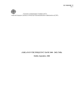
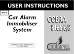
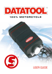
USER GUIDE
Welcome
Thank you for choosing the new Datatool® S4 Alarm
system for your motorcycle. The system provides
many unique features designed to increase the
protection of your machine or to customise its
operation to meet your individual requirements.
Some of these features can only be adjusted by your
dealer and are dependent on local regulations. For
these reasons, we advise you to discuss the options
available with your installing dealer.
We also advise you read this manual carefully and
keep it safe for future reference.
This manual covers the following products:
• Datatool ® S4 Red, Alarm/Immobiliser system
(insurance approved for all motorcycles)
• Datatool ® S4 Green, Alarm Upgrade system
(insurance approved for machines already complying
with Thatcham category 2 immobilisation. Visit
www.thatcham.org for the latest listings).
• Datatool® S4 Yellow, Alarm/Immobiliser system
(insurance approved for machines up to 125cc’s)
Please be aware that insurance companies may on
occasion apply other requirements regarding the
cover of machines.
General security advice
This security system is designed as a deterrent and
is not in itself a guarantee against theft. We advise
you, that the more difficult you make your machine
to be stolen, the lower the potential risk. Applying
common sense each time you park and securing
your machine plays a large part in this.
For further advice please visit www.datatool.co.uk
2
Registering the system
Remember to complete and return your certificate
of installation to Datatool® (UK) Ltd in the self
addressed envelope enclosed within 30 days of the
date of installation to ensure you are fully covered
for warranty.
Your unique tag ID (UK only)
Your security system contains an internal transponder
tag recognised by all UK police forces which is
unique to your alarm only. Registration of your
system adds this unique identification code to our
database and enables the police to identify the alarm
to your machine in the event of theft. The unique
code contained within the transponder can lead to
the prosecution of any person or persons in
possession of the alarm. This technology has already
resulted in many successful prosecutions and is an
additional deterrent to the would-be thief.
NOTE: For security reasons, the internal ID tag can
only be registered to the machine the alarm was
originally installed to. Therefore the alarm should
never be transferred to a different machine. Should
the original machine be stolen the alarm will still be
registered to it and you would have a registered
stolen part on your current machine.
NOTE: If you fail to register your machine your unique
ID tag will not be added to our system.
We would recommend that you upgrade the tagging
system by fitting the specially designed Datatool® S4
Tagging Upgrade Kit, only available to S4 security
system owners, which brings the parts marking up
to insurance standards at an enhanced price.
Should you wish to parts mark your machine to a
higher standard, the Datatool® Gold Tagging Kit is
available from your dealer to further reduce its
desirability to the potential thief.
Your remote control
All S4 systems come supplied with 2 remote
controls as standard. It is possible to add up to
4 extra remote controls (6 in total).
This is not a standard part of the installation and
your installer may levy a small charge at their own
discretion for carrying this out on your behalf.
The pictures below show the type of transmitter
supplied with your alarm depending on the type
purchased.
Should you require a combined ignition key and
remote control for the S4 Yellow, it is possible to
purchase the S4 Red remote control and code it to
the Yellow type alarm. You should discuss this with
your dealer.
The middle picture shows the S4 Red/Green
transmitter which has been converted for added
convenience with a key from the original motorcycle.
S4 Red/Green standard
S4 Red/Green conversion
completed
S4 Yellow
What the buttons do:
There are two buttons on your transmitter.
• The GREY button controls the main arm/disarm
functions of the system.
• The BLACK button controls secondary functions
such as movement sensor deletion (Ferry Mode)
and panic/locate.
Combinations of these buttons control further
functions (described later in the manual).
Should you wish to change the operation of the alarm
from the factory default setting, refer to the relevant
section within this manual for information on how
this effects the operation of the system. If you
require further guidance you should contact your
installing dealer.
3
Changing your remote control battery
Models S4 Red and S4 Green
Each remote control contains a single long-life
lithium battery (CR1616). This battery will normally
last at least 12 months. Normal range for the remote
control is around 10 metres. As the battery within
the remote control comes to the end of its life, you
will notice a reduction in its range and the battery
should be replaced.
1. To replace the battery remove the small screw
from the ‘key end’ of the remote and split the two
halves of the case.
NOTE: Take care not to lose the screw and ignition
key blade/transponder if the key conversion has
already been carried out.
2. Lift the printed circuit board from the remote.
3. Slide out the circular CR1616 battery from its
holder noting the polarity.
4. Maintaining the polarity of the battery, slide the
new battery into the battery holder.
5. Fit the PCB into the rubberised holder and check
an OE transponder chip is still located within the
top half of the casing.
6. Fit the assembly into the top casing so the GREY
and BLACK buttons drop into their respective
holes. At this stage it is a good idea to press the
remote control buttons to check they are operating
correctly, this will be shown by the LED on the
remote control illuminating.
7. Refit the ignition key blade into its holder, if
required.
8. Clip the bottom half of the casing to the top half,
replace and tighten the screw holding the two
halves securely.
4
Model S4 Yellow
The S4 Yellow transmitter contains a single CR2032
Lithium battery. This battery will normally last at least
24 months. (See S4 Red and Green for range and its
reduction with age).
1. Use a small coin, placed in the recess between the
two case halves near the key attachment hole, to
split the casings.
2. Lift the circuit board from the rubberised seal.
3. Remove the CR2032 Lithium battery from its
holder noting the polarity.
4. Maintaining the polarity, fit a new battery into the
holder and then refit the circuit board into its
rubberised housing.
5. Line up the two case halves and snap them
together
6. Finally test the remote control for correct operation
by operating the alarm.
NOTE: For the safe use and disposal of batteries,
please refer to the relevant section at the end of this
manual.
If you are unsure or have trouble in replacing/
sourcing a battery your Datatool ® dealer will be able
to assist you.
5
Operating the alarm system
This section explains fully how the alarm system
works. For a more basic explanation refer to the
credit card sized instructions (S4 Quick Reference)
supplied. We advise you to carry the quick reference
card with you for roadside guidance.
Fully arming the alarm system
Arming the system
To fully arm the alarm system to give movement,
nudge, trigger switch and battery back-up coverage,
press the GREY button on the remote control within
45 seconds of turning the ignition off. The
indicators will flash twice. (The S4 Yellow does not
have battery back-up).
Passive arming
Unless the unit has been placed in ‘winter’ mode, the
system will always passive arm 45 seconds after
the ignition is turned OFF.
NOTE: It is possible for your dealer to add
Arm/Disarm beeps to the system via the
customisation software switches so the system gives
audible signals also when it is armed/disarmed.
When the ignition is turned OFF the LED will light
continuously before emitting a set of increasing rate
beeps in the last 5 seconds.
NOTE: The inclusion of arm and disarm indication
beeps is strictly forbidden in all EU countries.
The LED changes to flashing to indicate the system is
activated.
When set to the factory default the system passively
arms the immobiliser and ignition trigger only.
If you wish to make the alarm fully arm passively you
can do this via the software switches covered within
the customisation section of this manual.
The LED will start to flash 5 seconds after the alarm
is armed and will be fully active after 20 seconds.
If you have changed the default settings within the
software section and selected FULL passive arming
of both the alarm and immobiliser, the alarm will
automatically arm along with the immobiliser (except
on the S4 Green model) 45 seconds after turning off
the ignition.
You can still arm it instantly by pressing the GREY
button of the remote within the first 45 seconds after
turning off the ignition.
If the system has passively armed as an
immobiliser and you wish to arm it fully, simply
press the GREY button TWICE. The first press
disarms the system, the second arms it fully.
Press to arm
6
2 flashes,
LED flashes 5 seconds after
arming. System is fully
armed after 20 seconds.
Arming the system without the
movement sensor (‘Ferry’ Mode).
To arm the alarm system but have both the
movement and nudge sensors turned off; press the
BLACK button within 10 seconds of arming the
system with the GREY button.
The indicators will flash twice to indicate the alarm
has been armed and then indicators will flash three
further times to confirm the movement sensors have
been turned OFF.
The system will still have immobilised the machine
(except with S4 Green model) and the alarm will
react if the machine is hot-wired, the supply to the
alarm is tampered with or one of the trigger switches
is activated.
If you press the BLACK button after more than 10
seconds of arming the alarm nothing will happen and
the alarm will still remain fully armed with the
movement sensors ON.
Disarming the system
To disarm the system from the armed state, simply
press the GREY button on the remote control.
The unit will then flash the indicators once to indicate
it has been disarmed.
Turn the ignition on within 45 seconds or the
system will automatically re-arm in the same state
as it was armed prior to disarming.
NOTE: Each time the system is disarmed the LED will
flash to signify the total number of remote controls,
including PIR’s, coded into the system. This ensures
you will always know you are in possession of all
remote controls capable of operating your system.
If you find there are extra, unknown remote controls
coded into your alarm, your dealer can exclude these
from the unit. Your dealer may levy a small charge at
their own discretion for this service.
This process has to be carried out EVERY time you
wish the alarm to be in ‘Ferry’ mode.
NOTE: If you have selected full passive arming and
wish to have the alarm in ‘Ferry’ mode you must arm
the alarm as stated above. The alarm cannot be put
into ‘Ferry’ mode after it has been ‘PASSIVE’ armed.
Press to arm
2 flashes
Press within
10 seconds
3 flashes
Press to disarm
Flash once, LED flash
according to number of
remote coded to the alarm
7
Disarming the system after it has been triggered
If the system has been triggered in your absence,
a long audible tone will be heard when the alarm
system is disarmed using the transmitter.
The system includes a diagnostic mode, which allows
you to identify the circuit that triggered the alarm
system.
After the long audible tone, the siren will beep and
the LED will flash a number of times to indicate what
triggered the alarm system.
Diagnostic chart
No. of Beeps Reason
Automatic re-arming
To ensure the machine remains covered at the level
chosen the last time you armed it, when the system
is disarmed it automatically starts a 45 second
countdown after which the system will automatically
re-arm at the SAME level as it was last armed in
(i.e. passive immobiliser, full alarm or full alarm
minus movement sensors).
If the ignition is turned or one of the trigger
switches is operated (e.g. seat removed if the switch
is fitted to it) within the 45 second countdown period,
the unit will passively immobilise.
1
The Positive or Negative supply to
the alarm has been lost (the fuse
may have blown)
NOTE: If full passive arming has been selected and
the ignition is turned ON/OFF the alarm will
re-arm fully.
2
The alarm has detected the ignition
being turned on whilst armed
If one of the trigger switches has been operated the
alarm will only immobilise.
3
Movement Detection – Motorcycle
has been moved (not applicable to
S4 Yellow)
Silent arming/disarming
4
Shock Sensor Detection – Motorcycle
has been nudged too many times
5
Trigger switch 1 has been initiated
6
Trigger switch 2 has been initiated
(not applicable to S4 Yellow)
To arm/disarm silently, simply press the BLACK
button of the remote control followed by the GREY
button. The system will arm or disarm for this one
operation and only flash the indicators.
7
Remote PIR Trigger – Remote trigger
from PIR sensor
NOTE: The inclusion of the arm and disarm indication
beeps is strictly forbidden in all EU countries.
If you have asked your dealer to select the
arm/disarm tones you can still arm or disarm the
system without the tones on a one-off basis.
NOTE: The S4 Yellow product uses the shock sensor
for movement detection and is equipped with only
the potential for trigger switch 1 and no trigger
switch 2. Therefore diagnostic 3 and 6 are not
contained within the code sequence for this product.
All S4 Alarm systems store the last five triggers
within their memory. This can only be accessed by
an approved Datatool® Installer to assist them in
servicing your system.
8
Press BLACK
Press GREY
Flashes only
‘Sleep’ mode
All alarm systems use a small amount of current
during operation and we advise if the machine is to
be left for an extended period in the armed state, it
is left connected to a float charger suitable for
maintaining the condition of the battery without
damaging it, such as the Datatool® Battery
Conditioner (Pt No. 02012011).
However the Datatool® S4 systems include a three
level sleep procedure to reduce the current
consumption of the system as the motorcycle battery
starts to discharge. This system reduces the risk of
damaging the machine’s battery through being left in
a discharged state. The levels of sleep are as follows:
Level 1 – Switching Point 11.5 Volts
- The LED flash rate is slowed to once every 10
seconds.
- The receiver is switched off unless the LED is
turned on, (i.e. the alarm will only disarm as the
LED flashes).
All other features remain unchanged.
Level 2 – Switching Point 10.5 Volts
- The LED flash rate is slowed to once every 30
seconds and the brightness of the LED is reduced
- The Siren will give a low level audible beep
every 60 seconds to warn you of a potential
battery failure.
Level 3 – Switching Point 9.8 Volts
- The LED is turned OFF
- The Siren Beep is turned off
- The internal battery back-up is turned off
If you wish to disarm the alarm, in sleep levels two
and three, turn the ignition on and press the GREY
button on the remote control.
Hazard warning lights
This is a hazard light warning feature for motorcycles
even if they do not have a hazard-warning switch.
Pressing both the GREY and BLACK buttons of the
remote control for 3 seconds when the ignition is
OFF and the alarm system is armed will start the
hazard warning lights.
NOTE: If the motorcycle battery voltage is too low to
maintain this feature, the lights will flash 5 times and
then stop.
To turn off the hazards either press both buttons
again for 3 seconds (leaves the system armed) or
press the GREY button to disarm the alarm system
and turn off the hazard lights.
NOTE: For safety reasons the hazard light feature
cannot be used with the ignition turned on.
- Shock Sensor is turned off (the movement sensor
remains turned on).
- The receiver is switched off and the remote will not
turn off the alarm until the ignition is turned ON.
Press and hold GREY and BLACK at the same time
9
‘Panic/locator’ feature
Entering ‘Winter’ mode
Press and hold the BLACK button of the remote for
3 seconds with the ignition switched OFF to enter
‘panic/locator’ mode.
From the disarmed state, press both buttons on the
transmitter for 10 seconds with the ignition ON
until you hear a beep, after the ignition is switched
OFF the alarm unit will go into winter sleep mode.
The unit will now be completely shut down leaving
the machine and current usage below 250µA.
The siren will sound and the indicators will flash until
any button is pressed on the remote control to turn
the panic/locator mode off.
When triggered, the alarm system reverts to the
original state held before the button was pressed to
activate the panic/locate mode.
Ignition
ON
Press GREY
button
Press and hold BLACK button for three seconds
One flash,
one beep
Ignition
OFF
one beep
Press both buttons
for 10 seconds
Winter mode
Exiting ‘Winter’ mode
The purpose of this mode is to enable you to leave
the machine for long periods of time with the alarm
drawing an absolute minimum current (250µA) from
the machine’s battery. In this mode the alarm system
is no longer active and it leaves the machine
immobilised only.
To re-activate the alarm system the ignition has to
be switched ON and the alarm will give a series of
increasing rate beeps which last for 5 seconds.
Within this time press the GREY button on the
remote control or the alarm system will trigger.
Should you decide to place the machine in this state,
we strongly advise you to use further measures to
protect your machine with quality physical security
such as the Thatcham approved Datatool® Python
Lock and Chain system combined with a Datatool®
Fortress Ground Anchor.
NOTE: The machine’s battery will still naturally
discharge over time so we advise you to check
its condition periodically.
10
Once the unit has woken up it will come back as a
fully armed alarm/immobiliser. This ensures that if
the machine is attacked by a third party, it is fully
protected.
We would again advise you on the benefits of using
the Datatool® Battery Conditioner (Pt No. 02012011)
to maintain the condition of your battery during
extended stand up periods.
NOTE: Datatool® (UK) Ltd cannot be held responsible
for batteries which have failed due to mistreatment.
The PIN override system
ALL Datatool® S4 Alarms have a PIN disarming
feature. As a new product there is no PIN number
programmed into the alarm, therefore we strongly
recommend you enter your own 4 digit number
as one of your first priorities.
NOTE: If you do not enter a PIN number and lose or
damage your remote control whilst out, you will not
be able to disarm your alarm without accessing your
second remote control.
Should you lose all your remote controls and not
know (or have not entered) your PIN number, the
alarm system will have to be returned to Datatool®
to be recoded. This is a chargeable service.
Entering a new PIN code
To initialise the PIN number the following procedure
should be followed:
1. Disarm the alarm system using the remote
control. The LED will flash to signify how many
remote controls are coded into the alarm.
2. Immediately after this, turn the ignition ON, OFF
and ON within 5 seconds.
3. Press both buttons on the remote control within
10 seconds of turning the ignition back ON until
the siren beeps confirmation (3 seconds).
7. The LED will again start to flash rapidly for
3 seconds and then start to flash slowly along
with the beeps. Count the number of flashes or
beeps from the siren until it equals the second
digit of the required PIN and turn the ignition OFF
and ON.
8. Repeat the process for the 3rd and 4th digits.
9. Once you have entered 4 numbers, the siren will
beep one long tone to indicate their entry. You
then have to confirm your selected PIN number
by entering it again.
10. Turn the ignition ON and repeat the above
procedure with the same PIN.
11. Once re-entered, turn the ignition OFF to
complete the procedure. If the PIN is confirmed
correctly, then the alarm system will give 2 short
tones. If the PIN is confirmed incorrectly, then
the alarm system will give 3 long tones.
NOTE:
a) You can disarm the alarm system with the
transmitter at any time.
b) If the ignition is left off and no action is taken
within 3 minutes, the alarm system reverts to
normal mode.
c) If the ignition is left on for more than 10 seconds,
the alarm will revert to disarmed mode.
4. Turn the ignition OFF and ON.
5. The LED fitted to the machine will flash rapidly
for 3 seconds.
6. After 3 seconds the flashes will slow and a beep
will be heard with each slow flash.
Count the number of slow flashes or beeps from
the siren until it equals the first digit of the required
PIN and turn the ignition OFF and ON. If you wish to
enter a zero turn the ignition OFF and ON
immediately after the rapid flashes stop (i.e. before
the first slow flash).
d) There is no default PIN, therefore you must set a
PIN to disarm the system in the event of remote
control loss or failure.
e) The number 0000 cannot be used even if initialised.
Please write your PIN code here and on your credit
card instructions and store in a secure location
11
Entering a new PIN code
To initialise the PIN number the following
procedure should be followed:
Ignition
ON
Ignition
OFF
Ignition
ON within
5 secs
Ignition
OFF
ONE LONG TONE
To set
second digit
LED on bike
flashes rapidly
for 3 seconds
Press both buttons
simultaneously within 10 seconds
confirmation beep 3 secs
Press GREY button
To set
first digit
Ignition
ON
To set
third digit
To set
fourth digit
Repeat procedure to confirm new PIN
To confirm
first digit
One beep & flash
To confirm
second digit
To confirm
third digit
To confirm
fourth digit
One beep & flash
four beeps & flash two beeps & flash six beeps & flash
four beeps & flash two beeps & flash six beeps & flash
New PIN
TWO SHORT TONES
(3 long tones if incorrect confirmation)
DON’T WORRY IF YOU GET IT WRONG
You can disarm the
alarm with the
transmitter at anytime
If ignition is left OFF and
no action is taken within
3 minutes, the alarm will
revert to service mode
Changing your PIN
The PIN can be changed at any time simply by
repeating the above procedure. The original PIN will
be deleted and the new PIN will disarm the alarm.
NOTE:
1. The factory set PIN is 0000. This PIN will not
operate the alarm so it is important you set your
own personal PIN.
2. You cannot set a PIN without a valid remote
control. If you have no remote controls and do not
know the PIN, the system will have to be returned
to Datatool® for recoding and 2 new remote
controls. This is a chargeable service.
12
If ignition is left ON for
more than 10 seconds,
the alarm will revert to
disarmed mode
3. If you do not set a PIN you will not be able to
disarm the system should you lose or damage
your remote control.
4. The PIN is also required to add further remote
controls or change the operation of the alarm via
the software switches.
5. Should you require your dealer to change any
settings or add a new remote control you should
inform them of your PIN. They will still be able to
carry out customisation of the unit but they will
have to over-write your existing PIN and you will
have to re-enter your preferred number.
Disarming the system with your PIN
If the transmitter is lost or damaged, or the
transmitter battery is flat, the system can be
overridden by your chosen four digit PIN (Personal
Identification Number) used in conjunction with the
ignition switch. The PIN procedure can only be used
after a full alarm reaction has been initiated.
The procedure is as follows: 1. Turn the ignition ON to initiate an alarm reaction,
(this will be immediate if the alarm is armed, or
after 10 seconds if the immobiliser only is armed).
2. The alarm will sound for 30 seconds and the
indicators will flash for 30 seconds. Do not turn
the ignition OFF during the sounding phase.
3. When the alarm reaction stops, the motorcycle LED
will be on constantly for 5 seconds. During this
5 second period, turn the ignition OFF and ON.
4. The override procedure will start immediately,
indicated by rapid flashes of the LED for
3 seconds which then switch to a slow flash
combined with beeps as detailed within the PIN
entry section above.
5. Count the number of slow flashes from the LED or
beeps from the siren until it equals the first digit
of the PIN code and then turn the ignition OFF
and ON. Again if you have selected zero as your
first PIN number you must turn the ignition OFF
and ON immediately after the rapid flashes stop.
6. The system will then return to the rapid LED flash
sequence for 3 seconds and then go to slow
flashes/beeps. Count the number of flashes or
beeps from the siren until it equals the second
digit of the PIN code and then turn the ignition
OFF and ON.
7. Repeat the sequence to enter the 3rd and 4th
PIN numbers.
If entered correctly, the alarm will disarm and the
motorcycle indicators will flash once.
NOTE: As soon as the alarm system is disarmed, the
passive arming alarm (if selected) and passive
arming immobiliser periods will begin. Therefore, the
ignition must be switched ON within the 45 second
arming period, otherwise the alarm system (if
selected) and the immobiliser will passive arm.
Entering an incorrect PIN code will initiate a full
alarm reaction.
If an incorrect PIN code is entered three times the
unit cannot be disarmed by the PIN number for
2 minutes.
If you have done this, the LED will give double
flashes when the third incorrect code is entered
until the lock-out time has expired.
Initiate full alarm reaction by turning
the ignition ON and leaving it ON
During this 5 second
interval turn ignition
OFF and ON again
To enter
first digit
To enter
second digit
To enter
third digit
LED on bike flashes
rapidly for 3 seconds
To enter
fourth digit
One beep & flash
four beeps & flash
two beeps & flash
six beeps & flash
YOU NOW HAVE 45 SECONDS TO TURN THE IGNITION ON
AND START THE MOTORCYCLE
Until your transmitter is replaced or repaired, this procedure must be
repeated to disarm the system every time it arms.
Entering an incorrect PIN will initiate a full alarm reaction.
13
Adding extra remote controls
All systems come with two remote controls preprogrammed into the alarm unit. Should you require
extra or replacement remote controls they can be
purchased through any Datatool® authorised dealer.
i) Should you require more remote controls (or radio
linked PIR’s) to be coded into the system, press the
GREY button on each transmitter required, leaving
no more than 15 seconds between presses
You can have up to a maximum of 6 remote controls
operating the system at any one time.
j) The transmitter memory is a stack with six locations
operating on a first in first out basis. There is no
limit to the number of transmitters which can be
taught at one time but the 7th transmitter/PIR will
replace 1st, 8th will replace 2nd etc.
To add a new remote control use the following
sequence:
a) Disarm the alarm system using either a
transmitter or PIN code (please note the code 0000
cannot be used, so if you have not previously
entered a PIN number and have lost both remote
controls the alarm unit will have to be returned to
Datatool® to be cleared and have new remote
controls coded to it. This is a chargeable service).
b) Immediately after the LED flashes to signify the
number of remotes coded into it, turn the ignition
ON, OFF, ON, OFF and ON within 7 seconds.
k) Turn the ignition OFF and leave it OFF for 15
seconds to exit transmitter learn mode you will
hear, two long tones to indicate learn mode has
been exited.
l) Alternatively, if you want to enter the software
switches to customise the system to your
preferred settings turn the ignition OFF, wait for
two beeps and then turn it back ON (see next
section ‘Customising the system’).
c) The LED will enter rapid flash for 3 seconds and
then start flashing the LED slowly and beeping the
siren as previously described.
Removing lost or stolen
remote controls
d) Enter the PIN number as previously described.
Lost or stolen remote controls can be removed from
your system by any APPROVED Datatool® dealer.
e) When the PIN number has been entered correctly,
the siren will give a long tone (1 second)
f) Immediately after the long tone turn the ignition
back ON.
Should you wish to exclude a remote control, take all
remaining transmitters (including any garage PIRs
coded into the alarm) with the machine to your
chosen dealer for them to carry out the service.
g) Within 15 seconds press the GREY button on a
new transmitter to teach it to the system.
Your dealer may levy a small charge at their
discretion for this service.
h) The LED will immediately flash with the number
of the remote control coded into the system (if
this is a new transmitter, the number will be the
total number of transmitters currently coded into
the system).
NOTE: If you do not code in a remote control at this
stage, or find your lost transmitter, it can be simply
added by following the normal coding in procedure.
14
Customising the system
It is possible to change the operation of the security
system to suit your requirements (see transmitter
learn procedure for details on how to enter the
software switches).
2. Press the BLACK button on the remote control to
move backwards through the table to Switch 1
(one beep will be heard when the switch is
selected).
Once you have entered the software switch section
3. If 3 beeps are heard you have entered Switch 3
which requires a special engineer’s code to enter.
Exit this area by pressing the GREY button to enter
Switch 1 again and wait for the confirmation beep.
1. Press the GREY button on the transmitter to move
forward through the table to Switch 2 (two beeps
will be heard when the switch is selected).
Switch Function
Number
Default
setting
Method of altering setting/
accepting setting
Listen for the correct number of beeps and press both buttons to enter the software switch
1
Change siren tone
(eight tones available)
2
Full passive arming alarm/
passive immobiliser selection
3
Select engineer software switches
Changing the siren tone
1. Once you have found the siren tone selection
(switch 1), press both the GREY and BLACK
buttons of the remote control to select the
switch. A triple beep will be heard and the
siren will sound at a reduced volume.
Siren 1
Off
Sequential
GREY button = Next tone
BLACK button = Previous tone
BOTH Buttons = Accept tone
GREY button/LED ON = Full passive alarm
BLACK button/LED OFF = Passive immobiliser
BOTH buttons = Accept arming method
Operable by installation engineer only
2. Each press of the GREY button will move the siren
tone forward to the next. If you press the BLACK
button you will return to the previous tone.
3. Once you have decided the siren tone you require
press both buttons of the remote control. When you
have selected it a double beep will be heard and
you will return to the software switch selection.
15
Changing the passive arming
settings (passive immobiliser or full
passive arming)
1. Once you have found the passive arming selection
(Switch 2), press BOTH buttons of the remote
control to select the switch. A triple beep will be
heard confirming you have entered the switch.
3. Once you have set the alarm to your arming
preference, press BOTH buttons of the remote
control to confirm the setting, a double beep will be
heard and you will return to the software switch
selection.
To exit software switch selection simply turn the
ignition OFF completely.
2. The factory default setting for this switch is OFF. If
you wish to turn it ON (full passive arming of the
alarm and immobiliser) press the GREY button of
the remote control and the system LED will be lit
confirming you have selected full passive arming.
If you wish to return to passive immobiliser only,
press the BLACK button of the remote control and
the LED will be OFF to confirm the setting.
How to remove your machine’s battery
You can remove the battery at any time when the
system is ‘immobilised only’ or in ‘winter mode’.
Winter mode also stops the remotes operating the
system making this setting better.
If the alarm system has been armed, the internal
battery back-up system (S4 Red and Green only) is
also turned on and disconnection of the battery will
cause the alarm system to sound.
If you have changed the standard default setting of
the alarm to full passive arming the easiest way to
remove the machine’s battery is to select ‘winter
mode’ prior to removal of the battery.
16
Ignition
ON
Press GREY button
Press both buttons
for 10 seconds until
beep
Disconnect
battery
Ignition
OFF
Special features (Dealer selectable only)
The following features can only be accessed by an
APPROVED Datatool® dealer. Should you wish to have
a setting changed from the factory default please
discuss this with your dealer first. The factory default
settings have been chosen to deliver the optimum
performance from the system.
NOTE: The inclusion of arm and disarm indication
beeps is strictly forbidden in all EU countries.
The factory default settings are in bold text.
No.
Feature
Settings available
1
Erase other transmitter codes (save
code of transmitter being used)
This switch removes all remotes except the one
being used to carry out the process. Any remotes
required to operate the system MUST be re-coded
after carrying out this function
2
Return software switches to default
This setting returns ALL software switches to the
factory defaults, including customer set switches
3
System diagnostics with event memory
Gives last five trigger types in reverse order
4
Movement sensor adjustment
(S4 Red and S4 Green only)
4 settings 2 ˚, 3 ˚, 4 ˚, 5 ˚
5
Shock sensor adjustment
10 settings
Default setting level 8
6
Arm / Disarm Tones
On/Off
7
Panic
On/Off
8
Nudge sensor (S4 Red and S4 Green)
Off
On continuous warn-away with no trigger
Trigger on first nudge detection
1 Warn-away and trigger on second nudge
2 Warn-aways and trigger on third nudge
3 Warn-aways and trigger on fourth nudge
4 Warn-aways and trigger on fifth nudge
8a
Nudge (S4 Yellow)
Trigger on first nudge detection
1 Warn-away and trigger on second nudge
2 Warn-aways and trigger on third nudge
3 Warn-aways and trigger on fourth nudge
4 Warn-aways and trigger on fifth nudge
17
Extending your security
Extra siren/Pager output
This system contains a supplementary output which
becomes positive only when the siren is sounding.
This wire is identified by a green and yellow tag on
the end.
The position of this wire is detailed on your certificate
of installation.
This output can be used to drive extra sirens, pagers
or telephone diallers. Your dealer can give you advice
regarding any extras you may wish to add along with
costs.
WARNING: Do not connect the extra siren wire
directly to your motorcycle horn. Should you
do this, the output may be damaged.
Covering accessories
The alarm system has a secondary trigger input,
which in certain instances may be able to be
connected to the side stand or to be used to offer
some protection to detachable luggage etc, by
looping an extension cable through it.
This is not part of the standard installation so please
discuss this with your dealer.
Garage security
Your alarm system can be extended to give protection
to your garage whilst the machine is parked within it.
There are two methods available, a remote linked
passive infra-red detector system and a hard-wired
magnetic contact system.
The Magnetic Reed Switch System
(Part number 02012006)
If you wish only to protect the doors and windows of
the garage you can use the Datatool® garage security
kit. This directly plugs into the machine via an
accessory socket Part No 02012007.
18
The kit contains three magnetic reed switches along
with all the cables and fixings required to carry out
the installation to most normal garages. Extra
switches are available if required.
For this kit to work the alarm must be armed.
The Passive Infra Red system
(Part number 02012084)
This uses a battery powered sensor of a similar type
used in house alarm systems. This communicates
with the alarm system via radio waves so no direct
connection to the machine is required. The signal
coding used is unique to Datatool® products.
As the sensor communicates with the unit by radio
waves it needs to be coded into the alarm system
before it works.
Do not buy any other type of sensor as you will not
be able to code it into the system.
Details of how to code it to the sensor are contained
within the sensor kit.
It is possible to code more than one sensor to the
system. The maximum distance between the sensor
and the alarm system should be no more than 10
metres.
Please remember the PIR sensor will detect any
movement within its line of sight range, such as pets.
Please bear this in mind when selecting the position
for this type of sensor.
If you do not want the sensor to work temporarily do
not arm the alarm, simply allow it to passive arm as
an immobiliser only.
If you wish to further extend the coverage it is
possible to wire the magnetic switch kit detailed
previously directly to the PIR sensor instead of to the
machine. The sensor will then trigger the alarm
system through its radio link.
Safety notice on the care, handling
and disposing of batteries
NOTE: The battery used in this device may cause a
risk of fire or explosion or chemical burn if
mistreated.
• Do not short-circuit, charge or heat.
• Do not deform, take apart, insert in reverse;
observe the + and – markings on the battery and
equipment.
Do not dispose of batteries with standard household
waste and do not dispose of batteries in fire.
When used correctly, batteries provide a safe and
dependable source of power. However, if they are
misused or abused, leakage, venting, and in extreme
cases, explosion and/or fire can result.
Declaration of conformity
• Do not mix batteries. Replace all batteries at the
same time with new batteries of same system and
manufacture.
The declaration of conformity certificates applicable
to the Datatool S4 range of security systems can be
viewed at www.datatool.co.uk/product
• Clean contacts on the battery and the equipment
before inserting new ones.
Contacts
• Insert only the batteries which are listed in this
user guide. Store this manual for future reference.
• Do not directly weld or solder batteries.
• Do not take batteries apart.
• Do not dispose of batteries in fire.
• Do not expose battery contents to water.
For further information please contact Datatool® (UK) Ltd
by e-mail at [email protected]
Our website www.datatool.co.uk contains full UK
dealer listings along with links/contact details for all
international distributors.
It also contains information covering the rest of our
product range of rider safety security and information
products along with useful hints and tips regarding
securing your machine.
• Store unused batteries in their original packing and
keep away from metal objects which cause a
short-circuit.
• Remove batteries from equipment if it is not to be
used for an extended period of time.
Keep batteries out of the reach of children. Do not
allow children access to batteries. If a cell or battery
has been swallowed, the person involved should seek
medical assistance promptly.
Dispose of damaged or discharged batteries
according to legal regulation or law. Contact your
local environmental authority for more details.
19
Quick Reference Guide
Disarm
‘Panic/Locator’
Press GREY button
Ignition OFF for more than 45 seconds
With the system armed, press and hold
BLACK button until the alarm sounds.
To silence, press either button on the
remote control
Alarm fully
Hazards
Press GREY button within 45 seconds
of ignition OFF
Press GREY and BLACK buttons together
until the hazards start to flash. To turn
off press BOTH buttons again
Immobilise only
‘Ferry Mode’
Press BLACK button within 10 seconds
of arming the alarm fully
For full instructions on features please refer to the
main manual or visit www.datatool.co.uk