1
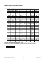
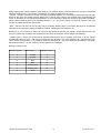
List of Contents
1. INTRODUCTION................................................................................................................................... 3
1.1 Definitions and abbreviations............................................................................................................................ 3
1.2 References ......................................................................................................................................................... 3
2. TECHNICAL DATA .............................................................................................................................4
2.1 General Modbus RTU ....................................................................................................................................... 4
3. COMMISSIONING.................................................................................................................................5
4. Modbus ADDRESSING MODULE .......................................................................................................6
4.1 Modbus function code ....................................................................................................................................... 6
5. Modbus HOLDING REGISTERS .......................................................................................................7
6. Modbus RS485 MODULE FOR MQU 99 ............................................................................................9
7. CONTACT..............................................................................................................................................10
Modbus RTU Module User Guide
1
V1.3 29-04 -2011
Modbus RTU Module User Guide
2
V1.3 29-04 -2011
1. INTRODUCTION
This manual describes the Modbus-RTU communication protocol.
1.1 Definitions and Abbreviations
CRC
Cyclic Redundancy Check, Used for error-checking in Modbus RTU. See
appendix
Modbus master
A Modbus device, which is able to access data in one or more connected Modbus
slaves
Modbus slave
A Modbus device, which is able to respond to requests from a single Modbus
master
Modbus address
Throughout this document the following notation is used to address Modbus RTU
registers:
• 1234 - Holding register
• 1234 (addressed in messages by 1233)
RS 232
Refers to the communication standard defined by EIA/TIA-232C. (Physical layer)
EIA/TIA232C
USB
Refers to the USB Specification usb.org
RS 485
Refers to the 2-wire communication standard defined by EIA/TIA-485. (Physical
layer)
RTU
Remote Terminal Unit – Standard Modbus transmission mode
1.2 References
Reference 1
Modbus over Serial Line
Specification & Implementation guide v. 1.0 Modbus.org 12/02/02
Reference 2
Modbus Application Protocol Specification v. 1.1
Modbus.org 12/06/02
Reference 3
MQU manual
Modbus RTU Module User Guide
3
V1.3 29-04 -2011
2. TECHNICAL DATA
Modbus RTU specification
Device type
Baud rates Recommended:
Slave
4800, 9600, 14400, 19200, 38400, 56000, 57600, 115200
bits/sec.
max. 31 per segment without repeaters
1-247
Modbus RTU (Other Modbus protocols like ASCII, Plus or
TCP/IP are not supported)
RS232, RS 485 - 2 wire, USB, Ethernet
• 3 read holding registers
• 16 write multiple registers
No
Reference 3
Device address range
Number of stations
Protocol
Electrical interface
Supported function code
Broadcast
Maximum cable length
Standard Modbus over
serial line v1.0)
Certified
No
2.1 General Modbus RTU
The module complies with the Modbus serial line protocol [Reference 1].
Among other things, this implies a masterslave
protocol at level 2 of the OSI model. One node,
(the master), issues explicit commands to one
of the „slave“-nodes and processes responses.
Slave nodes will not transmit data without a
request from the master node, and do not
communicate with other slaves.
Modbus is a mono master system, which
means that only one master can be connected
at any single point in time. Two modes of
communication are possible, Unicast and
Broadcast. Unicast mode is where the master
sends a request to one slave device, and waits
a specified time for a response. In Broadcast
mode the master sends out a request to
address „0“, which means that the information
is for all slave devices on the network. In
Broadcast mode there is no response from the
slave devices.
The Modbus frame is shown below, and is valid for both requests and responses.
Slave address
Function code
Data
CRC
1 Byte
1 Byte
0-252 Bytes
2 Bytes
Further details of the Modbus protocol can be found in Reference 1 and 2.
Modbus RTU Module User Guide
4
V1.3 29-04 -2011
3. COMMISSIONING
Before communicating with the master, Baud rate, node ID and update rate must be selected. This can be done
from the display. Please look in to the MQI, MQU transmitter manual to locate the Modbus RTU menu. (see
Reference 3).
Item
Slave address
Baud rate
Parity/framing
Response delay
Interframe
spacing
Value
1-247
4800, 9600, 14400, 19200,
38400,
56000,
57600,
115200
Even, 1 stopbit
Odd, 1 stopbit
None, 2 stopbit
None, 1 stopbit
0-255 msec.
3.5-25 chars
Modbus RTU Module User Guide
Comments
Device address [Factory setting: 1]
Communication speed [Factory setting: 9600]
Communication parameters [Factory setting: Even, 1 stopbit]
The minimum time from when a slave receives a request and
until it returns a response. This makes it possible to send data
to slow masters without overwhelming its receiver. [Factory
setting: 0]
The minimum interframe space between two Modbus RTU
messages in sequence (specified as 3.5 characters) is
configurable.
Range: 3.5 - 25 character times. [Factory setting: 3,5]
5
V1.3 29-04 -2011
4. Modbus ADDRESSING MODULE
The module allows R/W access to the following standard Modbus data register blocks:
• Holding registers
I.e. the module will not support the other standard data register blocks:
• Coils
• „Discrete input“
• „Input registers“
4.1 Modbus function codes
This device supports the following function codes: 3, 16 and 17.
Function code 3 and 16 are used for accessing registers. Function code 17 (report slave ID) will return a structure
of identification information of the device. Below the different function code exceptions are described.
Function code 3 (Read holding registers)
General exceptions:
• Requesting less than 1 or more than 125 registers => Exception 3 (illegal data value)
• Requesting more, than max. message size => Exception 2 (illegal data address)
• Requesting data, above/crossing limitation of max. register address (0xFFFF) => Exception 2 (illegal data
address)
• If the end address is only part of a mapped holding register item (e.g. one half of a longint value)=> Exception 2
(Illegal data address)
Application exceptions:
• Application errors => Exception 2 (illegal data address)
Holes/register alignment:
• The read command always returns data if no exception is given. Bad start/end alignment will result in only parts of
the data item being read.
• Holes in the holding register map return Exception 2 (illegal data address)
Function code 16 (Write multiple registers)
General exceptions:
• Exceeding max. message size => Exception 2 (illegal data address)
• Writing data above/crossing limitation of max. register address (0xFFFF) => Exception 2 (illegal data address)
Application exceptions:
• Application errors => Exception 2 (illegal data address)
• Application errors include writing to ReadOnly holding registers
Holes / register alignment:
• If start-address is not the start of a mapped holding register => Exception 2 (illegal data address)
• Writing to holes is not allowed => Exception 2 (illegal data address)
• If the end address is only part of a mapped holding register item (e.g. one half of a longint value), the action
depends on the data type.
• If the end address is only part of a mapped holding register item (e.g. one half of a longint value) => Exception 2
(illegal data address)
Modbus RTU Module User Guide
6
V1.3 29-04 -2011
5. Modbus HOLDING REGISTERS
In the following the holding registers for the MQU 99 Modbus RTU module are described.
Modbus
register
Modbus
address
No. of
bytes
1000
999
4
Float
-
-
HA [m]
R
1002
1001
4
Float
-
-
HB [m]
R
3
R
3
Data type Min Value Max Value
Descriptio
n
Read/
Write
1004
1003
4
Float
-
-
Qa [m /hr]
1006
1005
4
Float
-
-
Qb [m /hr]
R
1008
1007
4
Float
-
-
Fail
R
1010
1009
4
Float
-
-
3
R
3
Sa [m ]
1012
1011
4
Float
-
-
Sb [m ]
R
1014
1013
4
Float
-
-
Ta [h]
R
1016
1015
4
Float
-
-
Tb [h]
R
100
99
4
Long
4800
115200
102
101
4
Long
0
3
104
103
4
Long
1
247
106
105
4
Long
0
2
108
107
4
Long
0
70
110
109
4
Long
0
70
112
111
4
Long
0
255
Device info
R/W
1
0
1
Bool
0
1
Relay 1 ***
R
2
1
1
Bool
0
1
Relay 2 ***
R
3
2
1
Bool
0
1
Relay 3 ***
R
4
3
1
Bool
0
1
Relay 4 ***
R
Modbus
Baud Rate
*
R/W
Parity **
R/W
Slave
Address
Protocol
version
Device RT
Timeout
[ms]
Device RT
Timeout
reserve
[ms]
R/W
R/W
R/W
R/W
* 4800, 9600, 14400, 19200, 38400, 56000, 57600, 115200
If you write the wrong value to the Baudrate item, the default value 9600 will be written to this item.
** Parity values
0
None, 1 stopbit
Modbus RTU Module User Guide
7
V1.3 29-04 -2011
When writing to the Holding registers, data validity is not checked. Writing incorrect values can result in unexpected
behaviour of the device. In any further explanations, the following data types are used:
• Longint – Number consisting of 32 bits, formed by 2 Modbus registers. It is necessary to write both Low and High
Words of this item, the register number always has to be an even number. Not meeting these requirements will
cause an Exception 2 error (illegal data address). In case information about the number of decimals is available,
then the final number is given by the following formula: Y = X * 10^(- DEC), where Y is the final number, X the read
number, and DEC the number of decimals.
• Bool – this item can be read, but its value has no meaning. Writing value 1 to this item will cause an unspecified
operation to be performed (erasing the Memory module, resetting the flow totalisers, etc.
Reference 3). It is necessary to write both Low and High Words of this item, the register number always has to be
an even number. Not meeting these requirements will cause an Exception 2 error (illegal data address).
• Floating point – values are represented in standard IEEE format. Size of floating point value is 32 bits. Range
represented number is from 1.18E-38 up to 3.39E+38. Sign bit (bit31), the most significant bit represents the sign
of the number (0 for positive, 1 for negative). Exponent bits (bits 30 – 23), the next 8 bits represent the exponent.
Mantissa bits (bits 22 – 0), the remaining 23 bits represent the mantissa.
Data type memory map:
Modbus register
Data Type
Low/High Word
2
Longint
L
3
Longint
H
4
Bool
L
5
Bool
H
6
Floating point
L
7
Floating point
H
8
Word
--
Modbus RTU Module User Guide
8
V1.3 29-04 -2011
6. Modbus RS485 MODULE FOR MQU99
MQU99 communication modules and protocols (overview)
MQU99 ultrasonic flowmeters can be equipped with the following communication modules
*
• RS232C module with company protocol )
•
RS485 module with company protocol )
•
Modbus RTU RS485 module with Modbus and company protocols ). Selection between these protocols is done
by means of a module on-board jumper (Modbus – without jumper, company protocol – with jumper).
*
*
*
) Note about company protocol versions:
- MQU99 ultrasonic flowmeters have company protocol v.1,
Using Modbus RTU RS485 module at Modbus RTU mode
For this standard using Modbus RTU RS485 module, this module must be configured for Modbus protocol (without
corresponding jumper). Furthermore, MQU99 or flowmeter with Modbus RTU RS485 module at Modbus RTU mode
must have the following communication parameters (equal to factory settings):
Device address:
Baud rate:
R/T timeout:
31
9600 Bd
10.0 ms
These parameters are available by means of the flowmeter local keyboard and display (MAIN menu, RS 485 offer).
•
Modbus RTU RS485 module and SmartMQU software
SmartMQU data acquisition software can communicate in ELA-1 protocol only. Therefore, while using this software
with MQU99 flowmeter equipped by Modbus RTU RS485 module, this module must be configured for ELA protocol
(with corresponding jumper).
Modbus RTU Module User Guide
9
V1.3 29-04 -2011
7. CONTACT
Technical support: [email protected]
Windows life messenger: [email protected]
Sales office: [email protected]
Office hours:
8:30 – 18:00 (GMT+1)
Direct technical support:
8:00 – 16:30 (GMT+1))
Modbus RTU Module User Guide
10
V1.3 29-04 -2011