1
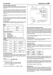
MAIN SYSTEM COMPONENTS
USER GUIDE
SYSTEM 3
Two Remote Transmitters
Installed Control Unit
Customising Wires
Installed Protective Trigger Switch
Installed In-Line Fuse and Spare Fuse
Installed LED Alarm Indicator
Warning Labels
SYSTEM 21
WARNING
All references to System 3 apply to
System 21 unless otherwise stated
UNAUTHORISED ALTERATIONS OR
ADDITIONS MAY INVALIDATE THE
WARRANTY AND CERTIFICATE OF
INSTALLATION
even if you read nothing else - READ THESE 2 POINTS!
ALWAYS CARRY A SPARE
IN-LINE FUSE
Set your own individual
PIN OVERRIDE
Make sure your installer advises you of
the location of the in-line fuse. If the
fuse fails, your motorcycle will be
immobilised until it is replaced.
This will let you disarm the system if
you lose the remote transmitter.
See pages 6 to 8
KEEP WITH YOUR MOTORCYCLE IN PLASTIC BAG PROVIDED
02005084
06/2003
INITIAL OPERATION - STANDARD MODE
When you collect your motorcycle, the Datatool System will be armed in STANDARD MODE.
In this mode the system arms automatically, 30 seconds after you switch off the ignition.
Before moving or starting your motorcycle, You will need to DISARM the system.
TO DISARM THE SYSTEM
The system will arm again automatically after
30 seconds if the ignition isn’t turned ON.
TO ARM THE SYSTEM
The system will arm automatically 30 seconds after the ignition is switched OFF,
or you can arm the system manually before this time.
FULL ALARM REACTION
Once triggered, the audible alarm will sound and the indicators will flash for 30 seconds,
the alarm will then switch off and reset automatically (See Diagnostic Mode).
To switch OFF the alarm manually, use the transmitter.
Page 1
OPERATION OVERVIEW
Four elements of the motorcycle are monitored and will initiate a full reaction if any
of the following occurs.
IGNITION CIRCUIT
BATTERY CIRCUIT
MOVEMENT
TAMPER
If the circuit is
hotwired, or the
ignition is forced.
If any part of the
circuit becomes live,
or the battery
connection is cut.
If the motorcycle is
moved or nudged
(with movement/
nudge detection on).
If there is any
attempt to gain
access to the alarm
control unit.
MOVEMENT/NUDGE DETECTION
In normal setting, movement/nudge detection is enabled automatically when the
system arms. Warning beeps will sound if the motorcycle is nudged or moved, too
many beeps within a certain time will initiate a full reaction.
Movement/Nudge detection should be disarmed
when you are filling with petrol at a garage, or
moving the motorcycle with the ignition off.
NEVER LEAVE THE MOTORCYCLE UNATTENDED WHEN MOVEMENT/NUDGE
DETECTION IS DISABLED
Page 2
OPERATION - SERVICE/VALET MODE
Engage Service Mode when you wish to service
or clean your motorcycle, or remove the motorcycle
battery.
IMPORTANT
If after entering service/valet mode you get more than one audible beep every 15
seconds, the system has been triggered in your absence and you have automatically
entered diagnostic mode (see diagnostics table on page 9).
YOUR MOTORCYCLE IS COMPLETELY UNPROTECTED IN SERVICE MODE
IMPORTANT
Protective Trigger Switch
A Protective Trigger Switch
is fitted to protect the
System Control Unit from
access eg: under the seat,
side panel or petrol tank. In
normal operation, if this is
tampered with a full alarm
reaction will be initiated.
In Service Mode, the
Protective Trigger Switch is
disarmed allowing access to
the area protected by it.
Page 3
HAZARD WARNING LIGHTS
A hazard warning lights function is included.
NOTE:
When entering Hazard Warning Lights Mode,
the hazard warning lights flash 5 times then
stop. The motorcycle battery is too low to
maintain this mode.
To switch off the hazard warning lights,
but leave the system armed, press
both buttons together for 3 seconds.
To switch off the hazard warning lights,
and disarm the system, press the
round button.
SLEEP MODE
If the level of charge in your motorcycle battery drops, the system will go into Sleep
Mode conserving remaining power.
NOTE: If the system does not come out of sleep mode in the normal way, hold the
transmitter button down, at the same time turn on the ignition.
Page 4
RIDER OPTION - Siren Tone Selector
You can choose one
of eight individual
siren tones.
The siren tone will be
subdued during the
selection process.
RIDER OPTION - Arming the system without Movement/Nudge Function
The System can be programmed to arm with the movement/nudge function disarmed
(Ferry Mode). This is achieved by securely grounding the Yellow wire.
NOTE: If you arm the system manually with the transmitter (within 30 seconds of
turning the ignition off) the system will arm with movement/nudge function armed.
Movement/nudge detection can be switched ON/OFF at any time with the transmitter
when the system is armed.
RIDER OPTION - Arming/Disarming the system in Silent Mode
The System can be programmed to
arm/disarm in silent mode. This is achieved by
securely grounding the white wire.
Page 5
PIN OVERRIDE - INITIAL PIN ENTRY
If your transmitter is lost or damaged, or the transmitter battery is flat, the System can be
overriden by a four digit PIN (Personal Identity Number) used in conjunction with the
ignition switch. The System is supplied without a PIN.
We recommend that you set your own individual four digit PIN as soon as possible.
The first time a new PIN is entered, you must have access to the in-line fuse.
Page 6
PIN OVERRIDE - CHANGE PIN
Page 7
DISARMING USING PIN OVERRIDE
If your transmitter is lost or damaged, or the transmitter battery is flat, the System
can be overriden by your four digit PIN used in conjunction with the ignition switch.
The PIN facility can only be used after a full alarm reaction has been initiated.
Until your transmitter is replaced or repaired, this procedure must be repeated
to disarm the system every time it arms.
Entering an incorrect PIN will initiate a full alarm reaction.
Carry your spare in-line fuse and transmitter when touring.
Page 8
SYSTEM REACTION DIAGNOSTICS
Reaction Indication
If the system has been triggered in your absence, a long audible tone will be heard when
the alarm is disarmed with the transmitter. If you wish to establish the reason for the alarm
being triggered, enter Service Mode and count the number of beeps emitted from the
alarm (see diagnostics table below).
To return to service mode - disarm the system (see page 1) and re-enter service
mode (see page 3).
Alarm Reaction Diagnostics
Number of Beeps
2
Reason for alarm being triggered
Power Failure (Alarm)
Fuse failed
Wires cut
3
Hot wire detection (possible theft)
Ignition tampered with
4
Movement detection
Motorcycle has been moved
5
Nudge detection
Motorcycle has been nudged too many times
6
Tamper circuit
Protective trigger switch has been initiated
Page 9
TROUBLESHOOTING
ALWAYS
CARRY A
SPARE
IN-LINE FUSE
System doesn’t
disarm or arm
manually
Make sure your
installer advises you
of the location of the
in-line fuse. If the fuse
fails your motorcycle
will be immobilised
until it is replaced.
If the replacement
fuse blows repeatedly,
or you continue to
experience difficulties
consult your dealer.
Starter motor
fails to function
(System 3 only)
•
Check the ignition switch is in the OFF
position.
•
Check the system fuse.
•
Check that you are within range of the
motorcycle (10m max.).
•
Under rare circumstances, the transmitter
operational range can be affected by radio
interference from other sources. This
problem can be overcome by moving the
transmitter closer to the motorcycle. In
extreme circumstances when the
interference is so strong that the transmitter
will not function, the system can be
disarmed using your PIN.
•
Check the condition of the transmitter
battery (see transmitter battery state maintenance).
•
Check (where applicable) that engine
‘Run/Stop’ switch is in the ‘run’ position, side
stand is up and motorcycle is not in gear.
•
Check the motorcycle battery is in good
condition.
•
Check the system fuse
(NB: if the indicators do not function when
arming/disarming or during reaction, this
indicates a failed fuse or lack of power
supply/earth to alarm system).
•
Check that the system will engage Service
Mode. If not, check all motorcycle fuses as
this indicates that the system is not
receiving an “ignition on” signal.
•
Failure of the system fuse
(see above).
•
Movement/Nudge detection too sensitive,
ask your installer to reset the sensitivity to
its least sensitive setting.
•
Protective Trigger Switch not set or
adjusted correctly.
IMPORTANT
(System 3 only)
If there is a failure
within the control
unit, or if the unit
detects spurious or
missing signals from
the motorcycle, the
alarm control unit will
not immobilise the
motorcycle until the
ignition is switched
OFF.
The motorcycle will
not start again until
the “fault” has been
rectified.
False alarms
can be initiated
by the following
Page 10
MAINTENANCE
TRANSMITTER
MOTORCYCLE BATTERY
The transmitter contains delicate electronic
circuits and must be protected from impact and
water damage. Do not remove soft plastic body
until batteries need replacing.
If the battery level falls, the alarm system is
equipped with ‘intelligent sleep mode’.
Low Transmitter Battery State
If three long tones are heard when the
transmitter operates, the transmitter batteries
need replacing.
REPLACE THE BATTERIES (two CR2016) as
soon as possible. Failure to do so will mean that
you are unable to disarm the system, and your
motorcycle will be immobilised (see pin override).
Replacing Transmitter Batteries
Clean the battery contacts and make sure that
the replacement batteries are of the correct type
and located in the correct position with the
polarity maintained.
New Transmitters
If one of your transmitters has been lost or
damaged, a new transmitter can be supplied. The
new transmitter will automatically cancel the lost
or damaged transmitter, so only two functioning
transmitters can ever exist. Contact your supplier
for full details of this service.
CONTROL UNIT
The control unit also contains delicate electronic
circuits and must never be pressure washed or
steam cleaned.
Intelligent battery chargers and optimisers are
available to maintain the motorcycle battery in
top condition, recommended types are Optimate
(DATATOOL Part No 02012011) and Airflow
(DATATOOL Part No 02012009). DATATOOL does
not recommend that any other charging device is
used unless the system has been put in
SERVICE MODE and the IN-LINE Fuse has
been removed prior to connection of the charging
device.
Contact your DATATOOL Installer for further
information.
GENERAL SECURITY
The DATATOOL alarm/immobiliser system will
provide an effective deterrent against theft. It will
not in itself guarantee that your motorcycle is not
stolen or damaged. We strongly advise that your
DATATOOL System is used in conjunction with
basic anti-theft precautions.
ACCESSORIES
A range of accessories are available to extend
the performance of your system. These are
available from your dealer or importer and
include:
•
Additional Remote Transmitters
•
Pocket Paging Alert (Available only in certain
countries)
•
Intelligent Battery Charger
WARRANTY TERMS AND CONDITIONS
Full written details of the Warranty Terms and
Conditions will be given to you by the DATATOOL
Authorised Installer.
BE SURE TO RETURN YOUR CERTIFICATE
OF INSTALLATION
DATATOOL Products are designed and produced in the UK by Datatool (UK) Ltd
Anstey Mill Lane, Alton, Hampshire GU34 2QQ United Kingdom
Telephone: +44 (0) 1420 541444 Fax: +44 (0) 1420 541447
Email: [email protected] web: www.datatool.co.uk