1
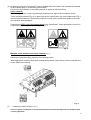
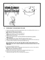
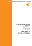
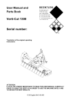
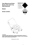
User manual and parts book Verti-Quake® Model: 3825 Serial number: NOTE: IN THE INTERESTS OF SAFETY AND ACHIEVING THE BEST RESULT, IT IS VERY IMPORTANT THAT THIS MANUAL IS READ CAREFULLY BEFORE USING THE VERTI-QUAKE®. 1212 English 915.120.204 PREFACE Congratulations with the purchase of your Verti-Quake®. This manual must be read and understood in order to ensure safe and long-term operation of this Verti-Quake®. Safe operation of this machine is not possible if the user is not fully familiar with the contents of this manual. The Verti-Quake® is not a stand-alone machine. It is the responsibility of the user to use the correct tractor. The user also has to perform safety-related checks on the tractor / Verti-Quake® combination including sound level, user instructions and risk analysis. The Verti-Quake® is solely intended for use on fields or other areas where grass can grow. The general safety instructions will be covered on the next page. All users must be familiar with and apply these instructions. There is a registration card below, which must be sent back in order to process any future claims. This user manual contains numerous instructions, which are numbered in sequence. This working sequence must be adhered to. The indicates a tip and/or note. pictogram indicates safety instructions. The pictogram All information and technical specifications used are the most recent at the time of publication. Design specifications are subject to change without notice. This document is a translation of the original user manual. The original user manual (Dutch language) is available on request. WARRANTY CONDITIONS THIS VERTI-QUAKE® IS SUPPLIED WITH A WARRANTY FOR DEFECTS IN MATERIALS. THIS WARRANTY IS VALID FOR A PERIOD OF 12 MONTHS FROM THE DATE OF PURCHASE. VERTI-QUAKE® WARRANTIES ARE SUBJECT TO THE “GENERAL CONDITIONS FOR SUPPLY OF PLANT AND MACHINERY FOR EXPORT, NUMBER 188”, WHICH WERE PUBLISHED UNDER THE AUSPICES OF THE UNITED NATIONS ECONOMIC COMMISSION FOR EUROPE. REGISTRATION CARD Complete the table below for your own records: Machine serial number Dealer name Purchase date Comments 2 ! Fig. 1 SAFETY INSTRUCTIONS ! The Verti-Quake® is designed for safe use. This is only possible if the safety instructions defined in this manual are observed in full. Read and understand (Fig. 1) the manual before proceeding to use the Verti-Quake®. Failure to use the machine as described in the manual can result in injury and/or damage to the Verti-Quake®. (1) The Verti-Quake® is solely intended for use on fields or other areas where grass can grow. The manufacturer accepts no liability whatsoever for incompetent use and any damage arising from this; the user bears full responsibility for all risks arising from this. The prompt and correct execution of the user, maintenance and repair instructions prescribed by the manufacturer also constitutes competent use. Inspect the area for treatment prior to using the Verti-Quake®. Remove any free-standing obstacles and avoid irregularities. (2) The Verti-Quake® has been manufactured in accordance with the latest technological knowledge and is safe for use. There is a risk of injury for the user and third parties if the machine is operated, maintained or repaired by improper persons. This must be avoided! Always use the Verti-Quake® in combination with the correct tractor, as defined in the technical data. (3) All persons appointed by the owner as authorised to operate, perform maintenance on or repair the Verti-Quake® must have read and fully understood the content of the operation manual and the Safety guidelines section in particular. The user is responsible for a safe Tractor / Verti-Quake® combination. The system as a whole must be tested for sound, safety, risk and ease of use. User instructions must also be drawn up. (4) The user has an obligation to check the Verti-Quake® for visible damage and defects before use. Changes to the Verti-Quake® (including the operation) that are detrimental to safety must be rectified immediately. For safety-based reasons, adapting or adding to the Verti-Quake® (with the exception of factory approved changes) is not permitted as a rule. Modifications to the Verti-Quake® will render the current CE marking ineffective and the person who performed the modifications is personally responsible for arranging new CE marking. Check the Verti-Quake® for loose bolts / nuts / parts prior to each use. Regularly check any hydraulic hoses and replace these if damaged or show signs of ageing. The replacement hoses must meet the manufacturer’s technical requirements. If present, the hydraulic system must be depressurised at all times before performing any activities on it. 3 The Verti-Quake® may NEVER be used if the safety guards and safety stickers are not present. NEVER crawl underneath the Verti-Quake®. Tilt the Verti-Quake® if required. NEVER get off the tractor while the engine is still running. The Verti-Quake® must be blocked to prevent it from lowering / driving off/ sliding away when performing maintenance, adjustment and repair activities. Always switch off the tractor engine, remove the tractor ignition key and disconnect PTO when performing maintenance, adjustment and repair activities (Fig. 2) Fig. 2 Only use original Verti-Quake® parts for maintenance or repairs so as to guarantee the safety of the machine and user. Adjustments and repairs to the Verti-Quake® must be performed by authorised, technical staff only. Maintain a repairs record. (5) In addition to the instructions in this user manual, the prevailing safety standards and Occupational Health and Safety regulations must be observed. The governing procedures of the traffic regulations apply to use on public highways. Transport of persons is not permitted! Do not use the Verti-Quake® during hours of darkness, heavy rain / storm or on slopes with a gradient greater than 20 degrees. 4 (6) All persons using the Verti-Quake® must be familiar with all functions and operational elements of the machine prior to commencing the activities. Connect the Verti-Quake® to the pulling vehicle as stated in the instructions. (Injury hazard!) Ensure that you have a clear long distance view and clear sight of the immediate vicinity. There are safety stickers (Fig.5) on both sides of the Verti-Quake® one on the side panel (Fig. 5) with an identical meaning. These safety stickers must be clearly visible and legible at all times and replaced when damaged. Persons must STAY out of the hazard zone of the Verti-Quake® when operational, as there is a physical injury hazard due to rotating parts. (Fig. 3) Fig. 3 Fig. 4 Maintain a safe distance of at least 4 metres! (Fig. 4) Observe the permitted lifting capacity of the pulling vehicle. Wear appropriate clothing. Wear steel toecap safety shoes, long trousers, secure long hair and do not wear loose clothing. Fig. 5 (7) Locations of safety stickers. (Fig 5.) Used oil / grease constitutes an environmental hazard and must be disposed in accordance with current regulations. 5 EU DECLARATION We, Redexim BV Utrechtseweg 127 3702 AC Zeist, the Netherlands declare entirely under our own responsibility that the product: VERTI-QUAKE WITH MACHINE NUMBER AS STATED ON THE MACHINE AND IN THIS MANUAL, to which this statement relates, is in accordance with the provisions of the Machine Directive 2006/42/EG. Zeist, 20/03/12 A.C. Bos Manager Operations & Logistics Redexim Holland 6 TABLE OF CONTENTS EU DECLARATION......................................................................... Fout! Bladwijzer niet gedefinieerd. 1.0 TECHNICAL DATA............................................................... Fout! Bladwijzer niet gedefinieerd. 2.0 GENERAL DESCRIPTION................................................... Fout! Bladwijzer niet gedefinieerd. 3.0 FIRST INSTALLATION, UNLOADING THE MACHINE FROM THE PALLETFout! Bladwijzer niet gedefin 3.1 PREPARING THE MACHINE FOR USE.............................. Fout! Bladwijzer niet gedefinieerd. 4.0 THE PTO .............................................................................. Fout! Bladwijzer niet gedefinieerd. 4.1 LENGTH OF THE PTO (fig. 8) ............................................. Fout! Bladwijzer niet gedefinieerd. 4.2 USING THE PTO.................................................................. Fout! Bladwijzer niet gedefinieerd. 4.3 PTO INFORMATION AND MAINTENANCE ........................ Fout! Bladwijzer niet gedefinieerd. 5.0 CONNECTING TO THE TRACTOR (Fig. 9)......................... Fout! Bladwijzer niet gedefinieerd. 6.0 ADJUSTING OPERATING DEPTH (Fig. 10) ....................... Fout! Bladwijzer niet gedefinieerd. 7.0 DRIVING SPEED ................................................................. Fout! Bladwijzer niet gedefinieerd. 8.0 START/STOP PROCEDURE ............................................... Fout! Bladwijzer niet gedefinieerd. 9.0 USING THE VERTI-QUAKE® ............................................... Fout! Bladwijzer niet gedefinieerd. 10.0 TRANSPORTING THE VERTI-QUAKE® .............................. Fout! Bladwijzer niet gedefinieerd. 11.0 DISCONNECTING THE VERTI-QUAKE® ............................ Fout! Bladwijzer niet gedefinieerd. 12.0 TROUBLESHOOTING ......................................................... Fout! Bladwijzer niet gedefinieerd. 13.0 MAINTENANCE ................................................................... Fout! Bladwijzer niet gedefinieerd. 13.1 CLEANING THE VERTI-QUAKE® ........................................ Fout! Bladwijzer niet gedefinieerd. 13.2 REPLACING THE BLADES ................................................. Fout! Bladwijzer niet gedefinieerd. 14.0 EU DECLARATION ..................................................................................................................... 21 7 1.0 TECHNICAL DATA Model Verti-Quake® 3825 Operating width 2.5 m (98.4”) Operating depth 380 mm (15”) Tractor speed measured at 540 RPM at PTO. 0.5 - 1.5 Km/h PTO RPM: (max.) 540 Weight 1602 Kg 0.3 - 0.9 mph 3532 lbs Number of blades 30 Number of blade disks 10 Distance between the blade disks 250 mm (9.84”) Thickness of the blades 15 mm (0.59”) Recommended tractor 80-120hp Minimum Lifting Capacity 2000kg / 4400 lbs. Hydraulic connection Double-action external hydraulic connection Maximum operating capacity 3750 m2/h 40365 ft2/h Machine dimension LxWxH ( height-adjustable leg in lowest position) 1.98 x 2.51 x 1.44 m 77.9”x98.8”x56.7” Three-point connection Cat. 2 Gearbox oil SAE 90 Lubricating grease Standard parts EP2 -Blades 15 mm (0.59”) -Rear roller -Integrated, height-adjustable legs -Hydraulic depth adjustment -PTO with coupling 2.0 GENERAL DESCRIPTION The Verti-Quake® is a machine designed to air grass fields. 8 Verti-Quake® Position 1 Position 2 Position 3 Fig. 6 3.0 FIRST INSTALLATION, UNLOADING THE MACHINE FROM THE PALLET The machine rests vertically on the pallet. To remove the pallet and place the machine on the floor horizontally, follow the instructions below: (fig. 6) !! NEVER CRAWL UNDERNEATH THE MACHINE !! 1. Secure a cable to lifting point and to the roller. (fig. 6 Position 1) Ensure that the cable / crane / lift can lift at least twice the weight of the machine (see section 1.0 technical data, to obtain information about weight). 2. Lift the machine and pallet approximately 50 mm (2") from the floor. 3. Ensure the machine rests on the outer part of the pallet. (fig. 6 Position 2) 4. Carefully and slowly lower the machine until its full weight is on the floor. (fig. 6 Position 3) !! WARNING! MAINTAIN A SAFE DISTANCE AS THE MACHINE MAY START TO SLIDE !! 5. Remove the upper 3-point pin. 6. Remove the lower 3-point pins (2x) and remove the pallet. 9 Fig. 7 3.1 PREPARING THE MACHINE FOR USE 1. Remove the access covers (2) by unscrewing the bolts (1) and taking off the covers. (fig. 7) 2. Take the accessories out of the machine. !! Take care! The blades are sharp !! 3. Connect the machine to a tractor; see section 5.0 Use the correct tractor; see specifications. 4. Lift the machine from the floor. 5. !! Ensure that the tractor is properly blocked and cannot move position independently !! !! Switch the tractor engine off before getting off the tractor !! 6. 7. Lower the height-adjustable legs (4) of the machine and secure them with the handles (3). 8. Carefully lower the machine on the height-adjustable legs (4). !! ENSURE THAT THE TRACTOR AND VERTI-QUAKE® ARE STABLE ON THE FLOOR AND THAT THEY CANNOT SUBSIDE OR SLIDE, BEFORE GETTING OFF THE TRACTOR !! 9. Unscrew the bolts (5) and nuts (6). 10. Assemble the blades, with the cutting edge aimed towards the rear roller of the machine. !! Take care! The blades are sharp !! Properly secure the bolts (5) and nuts (6). . 11. Replace the access covers (2) and secure by tightening the bolts (1). (fig. 7) 12. Adjust the tractor stabilizer to 50 mm lateral stroke. Determine the length of the PTO in accordance with section 4. 10 4.0 THE PTO The PTO is a very important part. It provides the drive from the tractor and ensures, if correctly maintained and installed, safe use of the machine. The PTO has dedicated CE certification. Read the PTO manual, which can be found on the actual PTO. A Max 30° Max 30° B 150mm (6") min. Fig. 8 4.1 LENGTH OF THE PTO (fig. 8) The length of the PTO is very important. The drive on the tractor and/or Verti-Quake® can become damaged if this is too long. The PTO may get damaged if the length of the tube overlap drops below 150 mm (6") at any given time. !! The length changes when the machine is lifted or if another tractor is used !! The procedure for correctly adjusting the length of the PTO if newly purchased or if another tractor is used is as follows: 1. Connect the Verti-Quake® to the tractor as described in section 5. 2. !! Switch the tractor off and ensure that the tractor is properly blocked and cannot move position independently !! 3. Lower the Verti-Quake® to the floor until the blades nearly touch the surface and the slider feet are parallel to the surface. 4. Measure the distance A between the PTO connection on the tractor and the Verti-Quake®, connection, from groove to groove. 5. Measure the length B of the PTO when in the shortest position from locking pin to locking bolt. 6. Split the PTO into two parts and remove the safety guards from both ends. 7. Both the ends of the tubes and the safety guards must be shortened. (B-A) + 75 mm (3”). 8. Burr all parts, use a little grease and reassemble all parts. 9. Fit the PTO with the cam coupling to the Verti-Quake® side. 10. Secure the other end of the PTO to the tractor. 11. Check the tube overlap. !! Never use the machine if the PTO safety guard is damaged: Replace this first. !! 11 4.2 USING THE PTO Correct use of the PTO requires checks of the following items: 1. When the Verti-Quake® is operational, the angle of the centres of rotation may never exceed 30 degrees. 2. The centres of rotation must always be aligned. 3. The minimum tube overlap is 150 mm. 4. Never use the machine if the PTO safety guard is damaged. 4.3 PTO INFORMATION AND MAINTENANCE The PTO of your Verti-Quake® machine has been fitted with cam coupling security which protects the Verti-Quake® against overloading. !! If the cam coupling is activated, the PTO must be switched off, the machine lifted from the ground and the start procedure must be repeated. !! Abridged maintenance schedule PTO. Periodic maintenance: Grease the lubricating points every 100 operational hours or after a long period of inactivity. Check the PTO for any damage to the safety guards and replace these if they are no longer sound. Check that the safety stickers are in place on the PTO and are not damaged. Annual maintenance: Remove the PTO from the machine. Inspect the PTO parts. All damaged parts must be replaced. Arrange all parts and carefully inspect them. Replace any damaged or worn parts. Clean all grip connections between parts. Reassemble all parts. Grease both tubes and reassemble both PTO parts. Reassemble the PTO and fit it to the machine. See the manual supplied with the PTO for additional information about maintenance and dismantling the PTO. The gearbox may be exposed to a higher load if the PTO has been shortened incorrectly or another tractor is used. This can cause damage. 12 5.0 CONNECTING TO THE TRACTOR (Fig. 9) Check procedure before proceeding to connect the Verti-Quake®: Check the Verti-Quake® for visual damage and repair this damage if the safe operation of the machine is no longer guaranteed. Check that all nuts and bolts are properly secured. Fig. 9 ® The Verti-Quake can be connected to the tractor using the 3-point coupling. The method is as follows: (fig.9) 1. Remove the 3-point pins (1) and (2) 2. Fit the PTO with the cam coupling to the PTO axle of the Verti-Quake®. 3. Carefully reverse the tractor into a suitable position for connecting the lower connecting arms to the frame. 4. !! Ensure that the tractor is properly blocked and cannot move position independently !! !! Switch the tractor engine off before getting off the tractor !! 5. 6. Connect the lower connecting arms using the 3-point connection plate pins (2) and secure this using the locking pins provided. 7. Fit the top rod of your tractor and turn this until it is the same height as the 3-point stop connection on the Verti-Quake®. 8. Connect the top rod (3) to the frame using pin (1); secure pin (1) using the locking pin provided. 9. Fit the PTO to the PTO axle of the tractor. 10. Connect the hydraulic tubes (6) to the outlet points of the tractor. 11. Screw the top rod in, creating tension on this. 12. Start the tractor and raise the Verti-Quake® from the floor. 13. Pull out the pins (4) and slide the height-adjustable legs (5) up. 13 6.0 OPERATING DEPTH ADJUSTMENT (Fig. 10) Fig. 10 1. If not yet connected, ensure that the Verti-Quake® is connected to the tractor as described in section 5. 2. Lift the Verti-Quake® using the tractor. 3. Activate the hydraulic outlet of the tractor and lower the slider feet. 4. !! Ensure that the tractor is properly blocked and cannot move position independently !! !! Switch the tractor engine off before getting off the tractor !! 5. 6. Remove the rear cover. 7. Remove the locking pins (2). 8. Pull the pins (3) out of the frame on either side of the machine and adjust the sliding legs (1) to the desired position. Consult Table 1 to achieve the desired operating depth. 9. Secure the pins (3) using the locking pins (2). 10. Activate the hydraulic outlet of the tractor and have the slider feet move up until stopped by the pins. The operating depth has now been set. 14 Fig. 11 Operating depth (assuming sharp blades) Depth Front Back 130 mm (15”) 1 1 150 mm (14.4”) 2 2 230mm (14.2”) 3 3 280 mm (13.8”) 4 4 330 mm (13.6”) 5 5 380 mm (13.4”) 6 6 Table 1 15 7.0 DRIVING SPEED The effectiveness of the airing treatment is determined by the condition of the ground, speed and the RPM of the PTO. When airing with the Verti-Quake®, the recommended speed is 0.5 to 1.5 km/h (0.3 – 0.9 mph) with a maximum PTO RPM of 540. The speed and RPM of the PTO must be set on the basis of an educated assessment of the ground condition and the desired level of airing. 8.0 START/STOP PROCEDURE The start procedure is VERY important. The Verti-Quake® can get seriously damaged if this procedure is not executed as described below. The start procedure is as follows: 1. Thoroughly inspect the Verti-Quake® and check that all parts are working properly. !! If not, the problems must be rectified first before using the Verti-Quake® !! 2. Connect the Verti-Quake® to the tractor. 3. Drive to the site to be treated. 4. Lower the machine until the blades nearly touch the surface. 5. Put the tractor into the correct gear with four-wheel drive engaged. 6. Increase tractor engine speed to approx. 1200 RPM and engage the PTO. 7. Increase the speed to ± 300 RPM 8. Put the tractor into motion and smoothly lower the Verti-Quake® into the ground. 9. Increase PTO speed to a maximum of 540 rpm. 10. Increase the driving speed up to a maximum of 1.5 km/h (0.9 mph) Fig. 12 Adjust the top rod so that the rear part of the slider feet runs parallel to the surface. This reduces the pressure of the machine on the floor and prevents damage to the surface!! (fig. 12) Work in straight lines; bends inflict damage to the surface / machine to be treated. 16 Stopping takes place as follows: 1. 2. 3. 4. 5. Stop the tractor. Reduce the speed of the PTO to ± 300 rpm. Gradually lift the Verti-Quake® from the surface. Stop the PTO once the blades are out of the ground. Proceed to the following site and repeat the procedure as described at the beginning of this section. !! NEVER engage the clutch of the tractor when operating the Verti-Quake®. The Verti-Quake® can push the tractor ahead at high speed !! Working in accordance with the procedure above is paramount. Placing the machine in the ground without the PTO running may seriously damage the machine. The Verti-Quake® must be lowered into the ground CAREFULLY. The machine is protected against overloading by means of an integrated security in the form of a cam coupling (see section 4.0 THE PTO). 9.0 USING THE VERTI-QUAKE® The following checks must be made before proceeding to use the Verti-Quake® at a site: 1. Are there any freestanding objects in the field? Remove them first. 2. Are there slopes? The Verti-Quake is only suitable for use on slopes with a maximum gradient of 20 degrees. Always work from the top to the bottom. 3. Are cables / pipes running in the ground? If so, establish their depth, and set the operating depth of the machine at 60% of this value. 4. Does the ground contain any solid objects? Adjust the operating depth. 5. Are there are any airborne objects in the area, such as golf balls, which will distract the user from the task at hand? If so, then the Verti-Quake® may NOT be used. 6. Is there a hazard of sliding or subsiding? If so, postpone the use of the Verti-Quake®. 7. If the surface is frozen or extremely wet; postpone activities until conditions improve. 10.0 TRANSPORTING THE VERTI-QUAKE® The user is responsible for transporting the Verti-Quake® behind the tractor on public highways. Consult national legislation for the regulations. In view of the weight of the Verti-Quake®, the maximum speed across open fields, with the machine elevated, is 20 km/hour (12.4 mph), circumstances permitting. Driving at higher speeds constitutes a potential hazard for the driver / bystanders and may even cause damage to the machine. A minimum of 20% of the weight of the tractor must be supported on the front axle when the machine is elevated. 17 11.0 DISCONNECTING THE VERTI-QUAKE® Fig. 13 The machine can be disconnected from the tractor in the following manner: 1. Drive the Verti-Quake® to a storage area with a stable / level surface. 2. !! Ensure that the tractor is properly blocked and cannot move position independently !! !! Switch the tractor engine off before getting off the tractor !! 3. 4. Remove the locking pin from pin (2) and pull out pin (2) from the height adjustable legs. Slide the height-adjustable legs (1) down. Secure the leg again with the pin (2) and locking pin. 5. Carefully lower the Verti-Quake® onto the surface. !! Ensure that the Verti-Quake® is resting stable on the surface before getting off the tractor !! 7. Release the tension on the top rod (3). 8. Remove the locking pin from pin (4) and pull out pin (4) from the rod connection. 9. Disconnect the PTO. 10. Disconnect the hydraulic tubes (5). 11. Remove the locking pins from the pins (6) and pull out the pins (6) from the de Verti-Quake® frame. 6. 12. !! Ensure that the Verti-Quake® is in a stable position !! 13. Start the tractor and drive away. 18 12.0 TROUBLESHOOTING Problem Possible cause Too much damage to the Blades are damaged. surface to be treated. Solution Try and align the blades by straightening them out with a hammer and anvil. Blades are bent. Align blades. Fit new blades. Machine and tractor are not in line. Adjust the machine, thereby aligning the blades with the tractor. Not driven in a straight line. Try and drive in a straight line. Soil is too wet. Postpone the work until the soil is dry. The airing shaft does not Cam coupling racing rotate. Gearbox is damaged. Start again Gearbox is leaking. Seal is broken. Replace seal. Cam coupling races too often. Cam coupling is worn. Replace cam coupling. Too many stones. Adjust operational depth. Surface too hard. Adjust operational depth. Speed too high. Adjust speed. PTO RPM too low. Increase PTO RPM. Tractor too light. Increase weight of tractor or select a different one. No 4wd. Engage 4wd. Machine wants to push tractor forward. Soil not sufficiently aired. Driven too fast. Soil is too wet. PTO RPM too low. Blades dig up too much soil. Repair or replace the gearbox. Drive slower. Postpone the work until the soil is drier. Increase PTO RPM. Blades are bent. Align blades. Fit new blades. Soil is too wet. Postpone the work until the soil is drier. 19 13.0 MAINTENANCE For safety reasons, adjustments and repairs to the Verti-Quake® must be performed by authorised, technical staff only. Only use original Verti-Quake® parts for maintenance or repairs so as to guarantee the safety of the machine and user. Time schedule / frequency Checkpoint / Lubrication point Method Prior to each use Check for loose bolts / nuts. After every 8 operational hours Check the oil level in the gearbox, this must be level with the gauge plug. Connect the machine to a tractor Look out and listen for and let it run idle for 5 minutes. strange noises / movements. Check for loose bolts / nuts. Tighten the loose bolts / nuts. Presence and legibility of the safety stickers (See Fig. 5) Loose parts around the PTO. Lubricate the PTO lubricating points. After every 50 operational hours Check the gearbox for oil leaks Tighten the loose bolts / nuts. Use SAE 90. Replace if damaged. Secure these parts, keeping them away from the PTO. Use EP2 lubricating grease. Replace gearbox seals. Grease the bearings of the blade Use EP2 lubricating grease. shaft. After every 100 operational hours Check the blades. Replace or try and repair. 13.1 CLEANING THE VERTI-QUAKE® The cleaning instructions for keeping the Verti-Quake® in the best possible condition are set out below. 20 Never aim a high-pressure cleaner on the bearing seals. Do not use aggressive soaps or cleaning agents Never clean the Verti-Quake® whilst in operation. Make sure the machine is stable and cannot slide or subside. Ensure the safety stickers are legible at all times. 13.2 REPLACING THE BLADES Fig.16 Follow the procedure below when fitting new or different blades (See Fig. 16): 1. 2. 3. 4. 5. !! Ensure that the Verti-Quake® is stable on the floor and that it cannot subside or slide !! Remove the access covers (2) by unscrewing the bolts (1) and taking off the covers. Remove the bolts (5) and nuts (6). Remove the blades to be replaced. Assemble the new blades, with the cutting edge aimed towards the rear roller of the machine. !! Take care! The blades are sharp !! Properly secure the bolts (5) and nuts (6). 6. Replace the access covers (2) and secure by tightening the bolts (1). 21