1
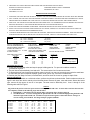
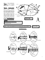
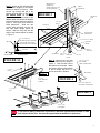
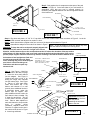
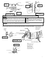
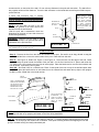
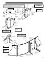
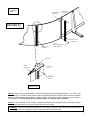
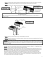
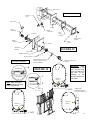
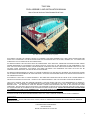
T3667-60A
POOL ASSEMBLY AND INSTALLATION MANUAL
Above Ground Aluminum Delta Sheetwall Oval Pools
Note: Deck and fence accessories shown are optional.
THIS MANUAL EXPLAINS THE CORRECT METHOD TO ASSEMBLE YOUR NEW SWIMMING POOL. READ THESE INSTRUCTIONS AND
STUDY THE ILLUSTRATIONS. ALSO READ INSTRUCTIONS FOR ACCESSORIES SUCH AS FILTERS, LADDERS, ETC. PAY PARTICULAR
ATTENTION TO THE CAUTIONS ON THE FOLLOWING PAGES.
THE MANUFACTURER IS NOT AFFILIATED WITH ANY PROFESSIONAL POOL INSTALLER, THEREFORE THE MANUFACTURER CANNOT
ASSUME RESPONSIBILITY FOR ERRORS IN THE INSTALLATION OF YOUR POOL BY THE INSTALLER OR THE HOMEOWNER. IF YOU
HAVE THIS POOL INSTALLED BY OTHERS, PLEASE SUPERVISE TO BE SURE YOUR POOL IS INSTALLED PROPERLY AND THAT ALL THE
CAUTIONS LISTED THROUGHOUT THIS MANUAL HAVE BEEN FOLLOWED. PAST EXPERIENCE OR SHORT CUTS MAY NOT BE
COMPATIBLE WITH OUR POOLS, FOLLOW THE INSTALLATION MANUAL.
THE MANUFACTURER RESERVES THE RIGHT TO CHANGE OR IMPROVE ANY ITEM WITHOUT INCURRING ANY OBLIGATION TO MAKE
ANY CHANGES OR IMPROVEMENTS ON ITEMS PREVIOUSLY SOLD AND TO DISCONTINUE MODELS OR CHANGE SPECIFICATIONS AT
ANY TIME WITHOUT NOTICE.
THIS PRODUCT IS SOLD WITH A "LIMITED WARRANTY". THE TERMS AND CONDITIONS ARE SET FORTH IN THE "LIMITED WARRANTY"
CERTIFICATE PACKED WITH EACH POOL. COPIES OF THE "LIMITED WARRANTY" ARE ALSO AVAILABLE UPON WRITTEN REQUEST.
YOUR LOCAL BUILDING CODE MAY REQUIRE OBTAINING A BUILDING PERMIT AND MAY HAVE REQUIREMENTS ON SETBACKS,
BARRIERS, ETC. ANY HOME BUILT OR PREFABRICATED DECKS SHOULD CONFORM TO THE LOCAL CODES, AND BOCA NATIONAL
BUILDING CODE.
THE ELECTRICAL CODE MAY REQUIRE A PERMIT AND INSPECTION, AND USE OF GFCI DEVICES OR OTHER
CONDITIONS. THE ELECTRICAL INSTALLATION MUST ALSO CONFORM TO ARTICLE 680 OF THE NATIONAL ELECTRIC CODE. INSTALL
THE FILTER AND PUMP IN ACCORDANCE WITH THE MANUFACTURERS INSTRUCTIONS. ARTICLE 680 STATES THAT YOU MUST BOND
THE SWIMMING POOL PUMP TO THE SWIMMING POOL. THIS CAN BE DONE BY ATTACHING A #8 COPPER WIRE FROM THE BONDING
LUG ON THE PUMP TO AN UNPAINTED METAL SURFACE ON THE POOL WALL OR BOTTOM CLIP.
THE INSTALLATION OF AN ABOVE GROUND SWIMMING POOL WILL USUALLY REQUIRE THREE PEOPLE TO HELP ASSEMBLE IT.
DANGER:
THIS POOL, EVEN IF SUPPLIED WITH A DEEP AREA, CONFORMS TO THE NATIONAL SWIMMING POOL INSTITUTE
STANDARDS FOR A TYPE O, NON-DIVING POOL. DIVING, SLIDING OR JUMPING INTO THE POOL MAY CAUSE PARALYSIS, DEATH OR
PERMANENT INJURY.
CUSTOMER SERVICE DEPARTMENT
8600 RIVER ROAD
DELAIR, NEW JERSEY 08110-3398 USA
1
DANGER
1. DO NOT DIVE OR JUMP INTO YOUR POOL. DO NOT USE A POOL SLIDE ON THIS POOL.
YOUR POOL CONTAINS SHALLOW
WATER AND IS NOT DESIGNED FOR HEADFIRST ENTRY (DIVING OR SLIDING) OR JUMPING. DIVING, SLIDING OR JUMPING CAN
RESULT IN A BROKEN NECK IF YOU STRIKE THE POOL. THIS CAN RESULT IN PARALYSIS, DEATH OR PERMANENT INJURY. INFORM
ALL FAMILY AND GUESTS OF THESE RULES AND POINT OUT WARNING LABELS.
2. IT IS NECESSARY TO MAINTAIN A 4’ HIGH BARRIER TO REDUCE THE CHANCE OF A CHILD ACCESSING AN UNSUPERVISED POOL.
THE BARRIER MAY BE A FENCE, WALL, OR COMBINATION THEREOF WHICH COMPLETELY SURROUNDS THE POOL. BARRIERS
MUST COMPLY WITH THE LOCAL BUILDING CODE, BOCA NATIONAL BUILDING CODE OR THE “CONSUMER PRODUCT SAFETY
COMMISSION” BARRIER STATEMENT. THE FOUR FOOT HIGH POOL WALLS USUALLY PROVIDE THIS BARRIER, HOWEVER IF THE
POOL IS LESS THAN 48” ABOVE GRADE, OR HAS BUTTRESSES (OVAL POOLS), YOU MAY NEED ADDITIONAL FENCING TO PROVIDE
THIS BARRIER. CONSULT WITH YOUR BUILDING OFFICIAL FOR SPECIFIC REQUIREMENTS. FENCING OPTIONS ARE AVAILABLE
FOR YOUR POOL, PLEASE CONTACT YOUR POOL DEALER.
3. YOU MUST MAINTAIN A 5’ WIDE “CLEAR ZONE” AROUND THE POOL AND DECK OR FENCING. DO NOT ALLOW TOYS, CHAIRS,
TABLES OR SIMILAR CLIMBABLE OBJECTS IN THIS “CLEAR ZONE”, ENABLING CHILDREN TO CLIMB AND GAIN ACCESS TO THE
POOL. THE FILTER EQUIPMENT MUST ALSO BE LOCATED OUTSIDE OF THE “CLEAR ZONE”.
4. YOU MUST RAISE AND LATCH, OR SECURE YOUR POOL LADDER OR POOL ENTRANCE WHEN THE POOL IS NOT IN USE.
Adherence to the above items will reduce the frequency of preventable child drownings in swimming pools.
WARNING
1. YOUR POOL IS SUPPLIED WITH WARNING SIGNS WHICH MUST BE AFFIXED TO THE POOL AS SPECIFIED. IF YOU BUILD A DECK,
THE TWO AREA SIGNS MUST BE AFFIXED TO THE DECK AT THE POINT OF ENTRY, VISIBLE TO PEOPLE ENTERING THE POOL
AREA. FAILURE TO INSTALL OR IMPROPER LOCATION OF SAFETY INFORMATION WILL SUBJECT YOU AND/OR THE INSTALLER
TO LIABILITY ARISING FROM INJURY CLAIMS.
A.
NO DIVING COPING: ( TWO SUPPLIED ) THESE ARE TO BE INSTALLED ACROSS THE POOL FROM THE POINT OF ENTRY,
B.
COPING WITH INTERNATIONAL LOGO: THIS ONE COPING IS TO BE INSTALLED AT THE POINT OF ENTRY, EITHER ADJACENT
AND HAVE ONE SECTION OF REGULAR COPING BETWEEN THEM.
TO THE “A” LADDER, UNDER THE IN POOL LADDER, OR IN THE CENTER OF A DECK.
C:
DANGER AREA SIGN WITH LOGO: (T1440) THIS SIGN MUST BE INSTALLED AT THE POINT OF ENTRY, FACING ALL USERS
AS THEY ENTER THE POOL. IF YOUR POOL HAS A FENCE, THE SIGN IS TO BE FASTENED TO THE FENCE, ADJACENT TO THE
LADDER OR ENTRANCE. IF YOUR POOL DOES NOT HAVE A DECK OR FENCE, ATTACH THE SIGN TO THE EDGE OF THE
COPING ADJACENT TO THE LADDER. THE SIGN MUST BE VISIBLE TO ALL USERS AS THEY ENTER THE POOL AREA.
D.
CAUTION - SAFETY RULES SIGN: (1445) THIS SIGN MUST BE ATTACHED TO THE FENCE DIRECTLY BELOW THE DANGER
SIGN OR IF YOU DO NOT HAVE POOL FENCING, ON THE COPING NEXT TO THE DANGER SIGN.
If any signs are missing or damaged contact the customer service department for replacements.
CAUTION
1. DECK SURFACES MAY BECOME SLIPPERY WHEN WET. DO NOT RUN OR DIVE INTO THE POOL FROM THE DECK. NOTE: SUNTAN
LOTIONS AND OILS MAY CAUSE POOL COMPONENTS TO BECOME SLIPPERY.
2. EACH MONTH CHECK THE POOL WALL FOR DETERIORATION OR LEAKAGE, ESPECIALLY AT THE SKIMMER AND RETURN
FITTINGS. THE SKIMMER AND RETURN GASKETS SHOULD BE REPLACED EACH SPRING TO PREVENT LEAKAGE.
DETERIORATION CAN WEAKEN THE POOL WALL WHICH COULD RUPTURE, RELEASING THE POOL WATER WHICH COULD CAUSE
BODILY HARM AND PROPERTY DAMAGE.
3. FOR NIGHT TIME USE, YOU MUST PROVIDE LIGHTING TO ILLUMINATE THE POOL, SAFETY SIGNS, AND DECK SURFACES. LIGHTING
MUST COMPLY WITH ARTICLE 680 OF THE NATIONAL ELECTRIC CODE. IT IS IMPORTANT THAT USERS BE ABLE TO SEE THE
SHALLOW DEPTH OF THE POOL AT ALL TIMES.
4. THE FOLLOWING BASIC LIFESAVING EQUIPMENT MUST BE ON HAND AT ALL TIMES:
A. A LIGHT BUT STRONG POLE ( SHEPHERD’S CROOK ) NOT LESS THAN 12’ LONG.
B. A 1/4” THROWING ROPE, AS LONG AS 1 1/2 TIMES THE MAXIMUM WIDTH OF THE POOL, WHICH IS ATTACHED TO A COAST
GUARD APPROVED FLOTATION DEVICE SUCH AS A RING BUOY.
C. A TELEPHONE SHOULD BE NEARBY WITH A LIST OF EMERGENCY TELEPHONE NUMBERS, SUCH AS POLICE, & AMBULANCE
2
5. ADDITIONAL POOL SAFETY RELATED PUBLICATIONS ARE AVAILABLE FROM THE FOLLOWING:
NATIONAL SPA AND POOL INSTITUTE
CONSUMER PRODUCT SAFETY COMMISSION
2111 EISENHOWER AVE
WASHINGTON, DC 20207
ALEXANDRIA, VA 22314
IMPORTANT INSTALLATION ITEMS
1. LEVELNESS; POOL MUST BE LEVEL WITHIN 3/4”. UNLEVEL POOLS PLACE EXTREME FORCES ON THE POOL WHICH MAY DEFORM.
2. WALL CLOSURE; THE POOL WALL MUST BE FASTENED TOGETHER PROPERLY WITH BOTH BARS AND FASTENERS IN ALL HOLES.
OMITTED BARS OR FASTENERS CAN CAUSE THE WALL TO RUPTURE, DESTROYING THE POOL AND INJURING PEOPLE.
3. SAND COVE; THIS SUPPORTS THE LINER AND MUST BE PACKED SOLID. IF IT COMPRESSES, SHIFTS OR ERODES THE LINER MAY
RUPTURE, RELEASING ALL THE WATER AND DESTROYING THE POOL AND INJURING PEOPLE.
4. THESE POOLS ARE NOT DESIGNED TO BE BURIED. THE GROUND FORCES CAN COLLAPSE THE POOL INWARD.
5. DO NOT LOCATE YOUR POOL NEAR STRUCTURES SUCH AS A HOUSE, GARAGE, ETC. AS PEOPLE COULD DIVE OR JUMP INTO
THE POOL RESULTING IN DEATH OR PERMANENT INJURY.
6.
ALTHOUGH THERE ARE RELATIVELY FEW PARTS IN YOUR POOL, NONE MAY BE OMITTED IN ASSEMBLY. EACH PART SUPPLIED
IS AN IMPORTANT PART AND IF OMITTED, MAY CAUSE POOL FAILURE. CHECK ALL PARTS AGAINST THE PARTS LIST.
WARNING:
Do not exceed the following torque values for the noted fasteners:
1/4” - 20 S. S. Fasteners
75 (in. lbs.)
3/8” - 16 S. S. Fasteners
236 (in. lbs.)
3/8” - 16 Aluminum Fasteners
143 (in. lbs.)
TOOLS AND MATERIALS
PHILLIPS SCREWDRIVER #2
HAND TROWEL
EXTENSION CORD
SLOTTED SCREWDRIVER #2
GARDEN HOSE & NOZZLE
STRING LINE
SOCKET WRENCH & SOCKETS
50’ TAPE MEASURE
HAND TAMPER
TRANSIT OR FARM LEVEL
ELECTRIC DRILL & BITS
GARDEN SHOVEL
1 LONG STRAIGHT 2 X 4 14’ LONG 1 ROLL DUCT OR FABRIC TAPE
25 WOOD STAKES
1 CAN WHITE SPRAY PAINT
PLASTIC GROUND COVER
SAND AND BLOCK CHART
POOL SIZE
12'x18'
12’x21’
12’x24’
15'x24'
15'x30'
18'x33'
SELECTING THE POOL SITE
TONS
2
2 1/2
3
3 1/2
4
5 1/4
SAND
YARDS
1 1/4
1 3/4
2
2 1/4
2 3/4
3 1/2
2” x 8” x 16”
PATIO BLOCKS
12
12
8
12
12
14
4” x 8” x 16”
CAP BLOCKS
2
4
6
4
8
8
HAMMER
RAKE
PLIERS
TORQUE WRENCH
WRENCHES
WHEELBARROW
NOTE: Sand must be
masons or bar sand and
be free of foreign objects
1. Check your local building codes and acquire proper building permits. For poor soil conditions consult a
professional engineer.
2. The pool site must be absolutely level and solid. The area must be free from stones and roots.
3. To protect the pool from chemicals and foreign matter in the soil, you may use a ground cover under the sand base.
Do not install your pool on asphalt, tarpaper, grass, wood, gravel, clay, concrete, or treated soils.
4. Position your pool away from trees, overhead wires, structures such as a house or garage or septic fields.
GROUND PREPARATION
Your pool must be installed on a solid level surface, perform the soil test as shown below. Position stakes as shown on
figure 1 and use a farm level or transit to level the area shown. Remove all grass, roots and stones. Start at the lowest
spot, remove all high spots, do not fill in low spots. The area must be absolutely level. Lines 1 through 6 of the
following table refers to Figure 1
Soil Test
Dig a hole in the pool area one foot square and one foot deep and fill with water. If at the end of one hour the water has
not completely soaked in, the following steps must be taken:
1. Round Ends: 3 patio blocks must be placed under each bottom clip as shown in figure 8.
2. Oval Midsections: A concrete footing must be placed under the end of each Delta upright along both sides and
down the length of the bottom rail. Consult a local professional engineer to determine the size and type of
concrete footing to be installed. The design load per upright is 4,000 lbs.
(ALUMINUM WALL)
OVAL POOLS
LINE “1”
12’ X 18’
7’ - 3”
12’ X 21’
7’ - 3”
12’ X 24’
7’ – 3”
15’ X 24’
8’ - 6”
15’ X 30’
8’ - 6”
18’ X 33’
10’ - 0”
LINE “2”
6’ - 3”
6’ - 3”
6’ - 3”
7’ - 6”
7’ - 6”
9’ - 0”
LINE “3”
7’ - 0”
10’ - 0”
13’ - 0”
10’ - 0”
16’ - 0”
16’ - 0”
LINE “4”
6’-0”
9’-0”
12’-0”
9’-0”
15’-0”
15’-0”
LINE “5”
17’ - 7”
17’ - 7”
17’ - 7”
20’ - 1”
20’ - 1”
23’ - 1”
LINE “6”
2’-8”
2’-8”
2’-8”
2’-8”
2’-8”
2’-8”
3
Step 1:
Parts Identification:
See figures in bill of material
packet. Check for installation
addendums.
Ground Layout:
Step 2:
Layout the area to be leveled as
shown in Figure 1. Measure
and mark with spray paint the
lines on the ground for your size
pool. Dig 2” deep to remove all
grass from within the pool area,
clear all debris and level this
entire area using a transit. Be
certain the area is smooth and
all grass, stones, roots and any
other foreign objects have been
removed. Do not build up or
fill low areas. Remove all
high spots.
LEVEL
LINE 3
LINE 5
DIAGONALS
LINE 6
LINE 1
LINE 4
LINE 2
POOL OUTLINE
EXCAVATION
OUTLINE
FIGURE 1
L00003B
CAUTION: For Oval Hopper Pools: If this pool is
being installed with a deep end refer to instructions
packed with the liner.
TRANSIT
NOTE: FASTEN TOGETHER ONLY THE CENTER INDICATED BY CIRCLES
FIGURE 2
L00034C
TIE STRAP LAYOUT
12’ X 24’
12’ X 21’
12’ X 18’
SHORT
TIE STRAP
SHORT
TIE STRAP
SHORT
TIE STRAP
LONG
TIE STRAP
LONG
TIE STRAP
FIGURE 5
FIGURE 5
LONG
TIE STRAP
FIGURE 5
LONG
TIE STRAP
15’ X 24’
LONG
STIE STRAP
FIGURE 5
LONG
TIE STRAP
FIGURE 5
SHORT
TIE STRAP
LONG
TIE STRAP
15’ X 30’
LONG
TIE STRAP
18’ X 33’
4
Step 3: Attach the left and right sides
of the delta uprights to the bottom
beams as shown in Figure 3. Slide
the tee clip through the slot in the
bottom rail and attach to the top of
the bottom beam as shown in
Figure 3A. Bolt the tie straps to the
adapter plate then attach the adapter
plate to the bottom beam as shown in
Figure 3. See Figure 2 for correct tie
strap placement.
Slide the two
correct delta interlocks over the left
and right delta upright pieces as
shown. Slide the vinyl cap onto the
ends of the bottom beams as shown
in Figure 3.
SHORT DELTA
INTERLOCK
(SLIDE DOWN TO TOP
OF BOTTOM RAIL)
DELTA
UPRIGHTS
FIGURE 3
BOTTOM
RAIL
A00001A
3/8” X 5/8”
BOLT
TEE CLIP
LONG DELTA
INTERLOCK
3/8” X 5/8” BOLT
TEE CLIP
5/8” X 1” BOLT
BE SURE TO BOLT THE TEE
CLIP TO THE TOP OF THE
BOTTOM MEAN AS SHOWN
BOTTOM
BEAM
3/8” NUT
5/8” NUT
TIE STRAP
BOTTOM RAIL
BOTTOM BEAM
FIGURE 3A
3/8” X 5/8”
BOLT
ADAPTER
PLATE
Step 4: Interlock the mud sills
into the bottom rail as shown in
Figure 3. Bolt the Mud sills to
the bottom rail as shown. Attach
the bottom rail/mud sill assembly
to the tie straps with #12 X 1”
screws as shown in Detail 4.
A00033
¼”-20 ½”
BOLT
3/8” NUT
3/8”-16 X 5/8” S.S.
CAP SCREW
3 PER CONNECTION
TIE STRAPS
DETAIL 4
#12 X 1”
SELF TAPPING
SCREWS
VINYL
END CAP
FIGURE 4
L00015C
3/8”-16 S.S. HEX NUT
NUTS ARE ON BOTTOM
¼”– 20 X ½”
NUT
FIGURE 5
A00029
4” X 8” X 16”
CAP BLOCK
If your pool is getting a walk deck or pool fence, attach the appropriate post holder or walk
deck support at this time. See manual supplied with the walkdeck or pool fence.
5
Step 5: Bolt together the tie straps across the span of the pool
as shown in Figure 4. Once both sides of your mid-section is
assembled, verify that your pool is squared properly by
measuring the diagonal distance from the two opposite corners
of the bottom rail. MUD SILLS
BOTTOM RAIL
3/8” X 5/8”
BOLTS
¼”-20 x ½” S.S.
MACHINE SCREW
3/8” NUT
FIGURE 6
ADAPTER
L00053
FIGURE 7
¼” - 20 HEX NUT
L00054
Step 6: Dig down and place a 4” X 8” X 16” cap block at the end of each bottom beam as shown in Figure 5. Level the
bottom rail with a transit and adjust to be certain it is level.
Step 7: Attach the transition uprights to the four corners of the bottom rail as shown in Figure 6.
Step 8: Assemble the adapter to the mud-sill as shown in Figure 7.
HINT: It may be helpful to crimp the bottom clip over
the wall channel to keep it from coming loose.
Important: To keep the wall on oval pools properly aligned with
the bottom rail, be certin to insert the 3’ angle in the correct
direction, and the bottom clips on the round ends must be 1/8” above the elevation of the top surface
of the bottom rail. Also pack the sand cove firmly against the wall along the midsection of the pool to
3” ANGLE
provide proper support. Failure to do this may cause a wrinkling in the wall around the bottom rail as LONG LEG DOWN
the bottom rail and uprights are fixed and
the wall must expand around it. Some
minor wrinkling may occur while filling the
pool, this is normal for this type of
midsection and does not pose any
structural risk.
Step 9: See Figure 1. Mark line
“2” as shown in the table on page
3. Insert the short wall channel
into the adapter. See Figure 8.
Create a half circle on line “2” by
sliding the longer wall channels
into the bottom clips. See Figure
8. Place a 2” thick patio block
under each bottom clip. If the
bottom wall channel is on soft
ground, place additional blocks in
a pyramidal shape under the
bottom clips for support. Also
place additional blocks under the
wall channel where needed. Dig
2” down for each block. The top
of each block must be at grade
level. Place a stake adjacent to
each wall channel to keep the half
circle
in
position
during
installation. Repeat for other end.
Place the 3” angles into the slot in
the bottom rail as shown in Figure
8. Insert long end down.
12X OVALS – SHORT WALL
CHANNEL (45 1/16”)
15X & 18X OVALS – SHORT
WALL CHANNEL (54 3/8”)
BOTTOM RAIL
ADAPTER
STAKE
WALL CHANNEL
2” X 8” X 16”
PATIO BLOCK
BOTTOM
RAIL
DETAIL 8A
*SLOT SIDE UP*
SKIMMER OPENING
A00032
BOTTOM CLIP
FOLLOW
LINE 2
STACKING
PATTERN FOR
POOR SOIL
FIGURE 8
L00008D
BENT BEAD
RECEIVER
CURVE TO FIT
LONG BEAD RECEIVER
SAND
Important: Remove the
plastic shipping film from
the wall prior to
attaching the enclosure
bars to the wall.
RETURN
FIGURE 9
W00012
6
1/4”-20 X 3/4” S.S.
MACHINE
SCREW
DUCT TAPE
INSIDE
OF POOL
1/4”-20 X 3/4” S.S.
MACHINE
INSIDE
OF POOL
OUTSIDE
OF POOL
WALL
WALL
ENCLOSURE
BARS
WALL
1/4”-20 S.S.
HEX NUTS
OUTSIDE
OF POOL
1/4”-20 S.S.
HEX NUT
FIGURE 11
FIGURE 10
L00036C
L00036
Important: Remove the plastic shipping film from the wall prior to attaching the enclosure bars to the wall.
Step 9 cont: See Figure 9, 10 and 11. Place the required amount
of sand inside the pool area. Starting at the center of a bottom
clip, insert the pool wall into the wall channel around the entire
pool area. Make sure the skimmer and return cutout are at the top
of the wall and not over a clip or upright. Attach the pool wall
NOTE: Start wall enclosure strip at the bottom
hole on the wall. If the enclosure strip does not
cover the last hole at the top of the wall, you
should attach it with a ¼” – 20 x ¾” machine
screw!
CAUTION: Installation of the wall in any other manner than precisely described above will cause extensive damage to
the pool and may result in injury or death to those people in or around your pool.
together as shown using the two (2) wall enclosure bars and hardware. The heads of the machine
PAN HEAD
SCREWS
SKIMMER
THROAT
GASKET
NOTE: THE TAB ON
THE BOTTOM AND
TOP CLIPS ARE ON
THE OUTSIDE OF
THE UPRIGHT
SKIMMER THROAT
GASKET (VINYL)
SKIMMER GASKET (CORK)
WALL
DETAIL 12A
UPRIGHT
W00030
FIGURE 12
W00025
DETAIL 12B
UPRIGHT
WALL
WALL CHANNEL
BOTTOM CLIP
LOW PROFILE / FRONT
ACCESS SKIMMER
#10 X 1/2” SELF TAPPING
SCREWS (4 PER UPRIGHT)
NOTE:
THE SKIMMER THROAT
GASKET MUST SANDWICH THE WALL. I.E.
ONE FLAP OF THE
GASKET MUST BE ON
THE INSIDE OF THE
WALL AND THE OTHER
ON THE OUTSIDE.
BOTTOM
CLIP
PATIO BLOCK
7
screws must be on the inside of the wall. Do not omit any fasteners in the pool wall connection. The wall will not
stay together without all the fasteners. Cover the bolt enclosure on the inside with several layers of fabric tape to
protect the liner.
If either wall enclosure strip is missing,
damaged or does not align properly with all
holes in the wall, do not use the wall and notify
your dealer at once.
DIMENSIONS
ARE TO TOP
OF WALL
NOTE: If the wall does not stay in the wall
channel, the ground is not level, remove the
wall and relevel the wall channel.
-After the pool wall is assembled, check the
dimensions of the pool to insure that it has not
shifted during assembly.
NOTE: TAPE A 3’ WIDE
PIECE OF PLASTIC TO
THE BASE OF THE
POOL WALL BEFORE
SPREADING THE SAND
TO HELP PREVENT
FUTURE WASHOUT OF
THE SAND UNDER THE
POOL WALL.
44”
50”
WALL
6” RADIUS
WALL
CHANNEL
WARNING: Failure to use the sand or sand
equivalent and shape it as specified will void all
warranties on the pool and liner.
FIGURE 13
Steps 13 through 15 are for overlap liners only.
For beaded liners proceed to step 16.
2” SAND BASE
W00013B
OVERLAP LINERS
Step 13: Remove the liner from the carton and unfold into the pool. Be careful not to drag, abrade or snag the
liner. Spread the liner out over the entire bottom of the pool. Raise the liner side wall.
Step 14: See Figure 14, Detail 14A, Figure 15 and Figure 16. Place the liner over the edge of the wall. Make
sure the overlap is equal around the outside of the pool wall. Cut the liner interlock into 2” pieces and center the
1 ½” pieces of the liner interlock over the liner at each upright. Place the bead receiver over the liner interlock and
liner as shown, to secure the liner in place.
Step 14A: See Detail 14B, for a J-Bead Liner. Place J Hook bead of the liner on top of the wall and push down
firmly. Then place the bead receiver or wall channel over the J-Bead liner and attach the top clips to the uprights.
Do NOT put the J-Bead liner in the bead receiver.
BEAD
RECEIVER
NOTE: LINER BOTTOM
SHOULD BE CENTERED
ON THE POOL USING
THE SEAM AT THE
PERIMETER OF THE
BOTTOM AS A GUIDE
BEAD
RECEIVER
LINER INTERLOCK
CUT TO 1 ½”
LINER
INTERLOCK
DETAIL 14A
NOTE: THE LINER
INTERLOCK
IS
USED AT EVERY
BEAD RECEIVER
JOINT AT EACH
UPRIGHT.
POOL WALL
SAND BASE
FIGURE 14
W00023
OVERLAP
LINER
POOL
WALL
DETAIL 14A
BEAD
RECEIVER
J-BEAD
LINER
POOL
WALL
DETAIL 14B
NOTE: If the liner is exposed to the sun for a long time, it will stretch and cause wrinkles. This can be avoided
by waiting until dusk or by spraying cold water on the liner during installation.
Step 15: Smooth all the wrinkles out on the bottom of the liner. To remove wrinkles, always pull the liner firmly
but gently. No sharp tugs! Be certain liner is centered. Time spent removing wrinkles and aligning the liner will
give you a neater looking and easily maintained pool.
8
TRANSITION
UPRIGHT
BEAD
RECEIVER
DELTA
UPRIGHT
BEAD
RECEIVER
OVERLAP
LINER
LINER
FIGURE 15
WALL
W00031A
WALL
FIGURE 16
W00032A
TRANSITION UPRIGHT
BEAD
RECEIVER
BEAD
RECEIVER
DELTA UPRIGHT
LINER
LINER
WALL
WALL
FIGURE 17
FIGURE 18
W00033A
W00034A
BEADED LINERS
Step 16: See Figures 17, 18 and 19. Place the bead receiver on the wall with
the ends centered over the uprights. Tape the joints of the bead receiver using
fabric tape to protect the liner.
DUCT TAPE
Step 17: Attach the transition top clips to the top of the transition uprights as
shown in Figures 20 and 21, based on the type of pool you have. For aluminum
frame pools, attach a #10 captive nut to the top clip prior to assembling the clip to
the transition upright.
Step 18: Attach a sheet wall upright over top of the transition upright as shown
in Figures 22 and 23, based on the type of pool you are installing. Lift up one
end of the bead receiver and slide the top clip completely onto the first bead
receiver until the ends of the bead receiver are centered into the top clip. Use
this same method on the round ends of the pool.
Step 19: Remove the liner from the carton and unfold into the pool. Be careful
not to drag, abrade or snag the liner. Spread the liner out over the entire pool
bottom.
Locate the triangle shaped tabs on the under-surface of the liner.
These tabs should be lined up with the four transition uprights on the floor of the
pool. Raise the liner sidewall and place the bead into the bead receiver.
Smooth all the wrinkles out on the bottom of the liner. To remove wrinkles,
always pull the liner firmly but gently. No sharp tugs! Be certain liner is
centered. Time spent removing wrinkles and aligning the liner will give you a
neater looking and easily maintained pool. The bead must be fully seated in the
receiver to prevent it from coming out later when filling pool. Check frequently
when filling pool with water.
LINER
BEAD
LINER
BEAD
RECEIVER
WALL
FIGURE 19
W00023
9
ATTACHING THE TOP CLIPS TO THE TRANSITION UPRIGHTS AT THE FOUR CORNERS OF THE OVAL:
TRANSITION
TOP CLIP
Note: When properly installed, the direction of the hole pattern
on this clip should form an arrow facing out of the pool.
FIGURE 20
BEAD
RECEIVER
DETAIL 17A
FOR ALUMINUM
POOLS WITH 5”
FRAMES
L00036B
#12 X ½” HEX
HEAD SCREW
4 PER
UPRIGHT
#10 CAPTIVE NUT
FACES
OUTSIDE
OF POOL
A00017B
TRANSITION
TOP CLIP
BEAD
RECEIVER
WALL
TRANSITION
UPRIGHT
#12 X ½” HEX
HEAD SCREW
4 PER
UPRIGHT
WALL
TRANSITION
UPRIGHT
FOR ALUMINUM
POOLS WITH 7”
FRAMES
FIGURE 21
A00017A
TOP CLIP
FIGURE 22
BEAD
RECEIVER
CAPTIVE
NUT
W00050
TRANSITION
UPRIGHT
TRANSITION
TOP CLIP
#10 X ½”
SELF
TAPPING
SCREW
DETAIL 23A
A0005C
7” FRAME
ALUMINUM
POOLS
SHEET WALL
UPRIGHT
#10 X ½”
HEX HEAD SCREW
4 PER UPRIGHT
SHEET WALL
UPRIGHT
10
5” FRAME
ALUMINUM
POOLS
TRANSITION
UPRIGHT
TRANSITION
TOP CLIP
FIGURE 23
W00051
SHEET WALL
UPRIGHT
SHEET WALL
UPRIGHT
#10 X ½”
HEX HEAD SCREW
2 PER UPRIGHT
*
TOP CLIP
BEAD
RECEIVER
CAPTIVE
NUT
#10 X ½”
HEX HEAD
SCREW
DETAIL 23A
A0005D
Step 20: Begin to fill the pool with water. Use a slow stream of water and fill approximately 1 1/2” deep. If the
pool is an oval, be certain that the blocks under the bottom beams have remained level and that the bottom
beams are seated firmly on those blocks. Make sure the fit of the liner is correct. Smooth out any wrinkles in
the pool bottom. If installing a deck, do not fill more than 12” until the deck is installed.
Step 21: Fill the pool with 4” to 6” of water. Measure the distance from the bead receiver to the water surface
at several points around the pool to be certain that the pool is still level.
WARNING: The pool must not be more than 3/4” out of level. If the pool is not level, drain the water and level
the structure. Any non-compliance with this requirement will void all warranties.
11
Step 22: Locate the safety warning copings as described and as shown at the back of this manual. Then attach
all sections of coping as shown in figures 24, 25 and 26 using the outermost holes in the top clips.
Step 23: See Figure 28. Assemble the coping covers as shown based on the type of pool you are installing.
#10 – 24 x 5/8”
CARRIAGE BOLTS
FIGURE 24
FIGURE 25
CO00022
COPING
C000012B
#12 x ½” SS TYPE AB
HEX HEAD WASHER
HEAD SELF-TAP
(4 PER TOP CLIP)
DELTA TOP CLIP
#10 – 24
HEX NUT
ALUMINUM POOLS
Note: Attach the midsection coping to the delta top clips first, then attach the coping and top clips to the delta uprights as a
complete assembly.
#10 x ½” SELF
TAPPING SCREWS
FIGURE 26
CO00021
BEAD
RECEIVER
Step 24: Fill the pool until the water level is 3 inches below the return hole.
Step 25: Follow the instructions for the filtration system, skimmer and return that are supplied with the filter. See
Figure 29 for additional assistance.
DANGER: When a filter or any other electrical device is added to this pool, it is the responsibility of the purchaser to
take all necessary precautions as set forth in article 680 of the National Electrical Code and local electrical codes.
Failure to comply with this requirement may result in a dangerous or hazardous electrical condition which may cause
bodily injury or death.
Step 26: Attach the remaining safety warning signs as described and shown in Figure 30. If installing a fence or
deck refer to those manuals for proper placement of safety information.
Step 27: Fill the pool up to the center of the skimmer, make sure that all fasteners are tightened properly and your
pool is correctly assembled. Upon completion of the pool it is important to backfill the pool wall to prevent the sand
from washing out from underneath and water from accumulating around the pool which can cause settling or
deterioration. Backfill should be sand or clean well draining soil. Do not use mulch or materials which retain
moisture, or limestone or materials which are corrosive. The backfill should be three to four inches up the wall, be
sure to cover the bottom beams, and slope away to provide runoff. Please read the “Sensible Way to Enjoy Your
Pool” booklet and enjoy years of swimming and relaxation.
12
COPING COVER ATTACHMENT FOR ALUMINUM POOLS
#10 –24 X 5/8”
MACHINE SCREW
COPING
COVER
BEND TABS TO
SECURE TO
THE COPING
ALUMINUM POOLS WITH ALUMINUM COVERS
#10 –24 X 5/8”
MACHINE
SCREW
FIGURE 28
A00027A A00028C, A00027B
PLUG
FITS THIS
WAY
ONLY!
#8 X 1”
SELF TAPPING
SCREWS
PLUG
#10-24 X 5/8”
MACHINE
SCREWS
ALUMINUM POOLS WITH RESIN COVERS
Face Plate
#8 X 1”
SELF TAPPING
SCREWS
13
POOL WALL
SKIMMER ASSEMBLY
TEFLON
TAPE
PIPE TAPE
LINER
HOSE
ADAPTER
HOSE
ADAPTER
LOCKNUT
FACE
PLATE
GASKET
FACE PLATE
SCREW
FIBER
WASHER
FACE
PLATE
LINER
SANDWICH
GASKET
FIGURE 29
POOL WALL
W00024
RUBBER GASKET
WALL FITTING
DIRECTIONAL BALL
(POINT OPENING AWAY
FROM SKIMMER)
RETURN ASSEMBLY
B
FIGURE 30
WATER SIDE
SA00003B
DANGER
SA00004
DANGER
SA00005
POINT OF
ENTRY
CAUTION:
B
D
D
C
A
A
POINT OF
ENTRY
WARNING:
After
completion of the
pool, the pool must
never be drained to
less than 1/2 full.
Damage
to
the
structure and/or liner
may result.
A
A
C
DECK SIDE
Note: Refer to Page 2,
Warning section for Label
Letter Designations.
DIRECTIONAL BALL
FITTING
C&D
ADDITIONAL
DANGER SIGN (SEE
SIDE DECK MANUAL)
A
POINT OF
ENTRY
B
A B
C&D
C&D
14