1
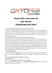
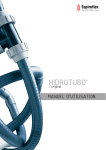
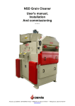
Electric Bike Conversion Kit
Installation’s Manual
V.1.6
May 2015
Table of contents:
Page
1.
2.
3.
4.
5.
6.
7.
8.
Before installation
Recommendation for washing
Installing the motor
Installing the battery unit
Installing the pedal assist sensor
Fitting the LCD console
Installing the brake cut off switches
Connecting the connectors
9. Connecting brake lever & throttle to the LCD
3
3
3
6
7
9
10
11
12
This manual applies to the OXYDrive CST 11Ah, CST 13Ah HT
conversion kits.
PLEASE NOTE: Not all the illustrations may apply to your specific
kit. This is a DIY conversion kit and some illustrations may vary
from the actual product purchased. The entire concept of fitting is
the same on all kits. Also note that installation of various bikes may
vary and there may be a need to take an individual approach for
every bike conversion. OXYDrive does not take any liability for the
damages caused to the bike frames or any other bike components.
The conversion kits are fitted at owner’s risk. There is no
guarantee that the conversion kit will fit without any problems to
any bike.
2
1. Before installation
Before installing this kit please note that there is a minimum skills
required to run a successful installation. If the end user feels
uncomfortable to carry on the assembly process it is advised to take it
to the nearest dealer or good bicycle shop with workshop facilities. To
run a successful installation the assembler will need the basic
workshop tools too. Please read the next chapter
2. Tools required for installation
All good bicycle workshops will have all necessary tools to carry on the
assembly process:
Tools required for installation:
- Set of allen (hex) keys, 2-6mm
- Cassette wrench
- Cable cutters
- 19mm spanner (wrench)
- Set of tyre levers
3
- Bicycle pump
- Flat and cross screwdrivers
3. Installing the motor
Step 1
Fit the bicycle tyre along with the rim tape to the new OXYDrive wheel.
Step 2A Fitting front wheel motor
Try to slot the motor into the forks drop outs. Please note that some forks may
only have a 9mm drop outs. The motor axle is 10mm and therefore may not fit.
IMPORTANT: The motor’s axle must slot in to the dropouts easily with
no use of any force. If you fork drop out is too narrow please use a file
to file off the surface by 0.5 mm on each side.
STEP 2B: Fitting rear wheel cassette motor
Before fitting the rear cassette motor into frame dropouts please fit the
cassette on the motors ratchet. You need to use the cassette tool to
tight up the cassette. The amount of torque used to tighten up
cassette should be specified on the locking nut of each cassette.
Always use good quality 19mm spanner to secure the locking nuts in
the frame.
Step 3
When fitting the motor regardless if its front or rear driven it is
generally better to direct the motor cable towards the bottom. It will
prevent then any possibility of water getting into the motor. For
mountain bike users this position of motor cable brings higher risk of
ripping the motor cable in the off road terrain.
4
Step 4.
It is crucial to pay extra attention of the order of fitting the locking
nuts.
Step 5.
For rear wheel driven kit
Securing the front wheel is very important. The locking nuts should be
well tight with a minimum torque of 12Nm.
5
IMPORTANT: The locking nuts and spokes should be regularly
checked every few rides to ensure the wheel is securely fitted.
4. Installing the battery unit
The battery holding unit should be fitted normally in the place of the
water bottle cage. Most of the bicycles already have ready made frame
mounts where the water battery holding unit can be attached to.
This manual does not give any recommendations on the bolts size or
torque as it all depends on the each individual frame requirements.
Please note that battery holding unit should be well secured to the
frame. Please use at least the same torque as for the water bottle
cage. For frames with a very think tubes it is advised to add additional
double sided counting tape (not included)
Warning to high performance tubing
Please note that some manufacturers’ use high performance double or
even triple butted tubing’s to reduce the weight of the frame. It
means that frame’s tubing’s are very weak in some sections and
should not be pressed with any kind of clamps. Please pay extra
attention when securing your battery holding unit with additional zip
ties to avoid the damage to the frame. OXYDrive does not recommend
to fit these conversion kits on the carbon frames.
6
Fitting the battery
In order to fit the battery follow the steps shown on the image below
The battery should be slotted on the holder’s rail and then drop down
to connect with controller connector. Then battery should be locked
with the key.
To remove the battery follow steps in the reverse order
7
5. Installing pedal assist sensor
The speed sensor that comes with the kit is designed to be fitted on
the left hand side of the bottom bracket. It perfectly fit square taper
axles but with minor modifications this can also be fitted to Shimano
Octalink or ISIS drives.
For Octalink and ISIS the standard magnet needs the internal hole to
be enlarged. To do that it’s best to file it of.
8
The magnet disc should be fitted on the axle with magnets located
approx 1-3mm from the speed sensor.
IMPORTANT: OXYDrive PAS sensor provided is currently compatible
with the square tapered bottom brackets. In some case if the axle is
too short or there is not enough room the bottom bracket might need
to be replaced for the one with longer axle. This can be modified to fit
Octalink and ISIS and Hollowtech cranks but if you have one of these
systems please contact us about availability of special Octalink,
Hollowtech sensors.
9
6. Fitting the LCD console
Currently there are two displays available for OXYDrive kits. C300 with
buttons integrated in the display should be fitted on the left hand side.
In order to fit this display the handlebar grip, shifters and brake lever
should be removed and the display should be slotted on the
handlebars.
There is also another way of fitting this display by removing off the
display the holding bracket and slotting it back when display is already
on the handlebars.
10
FIITING THE CENTRAL DISPLAY C6
In order to fit this display the handlebar grip, shifters and brake lever
should be removed and the display should be slotted on the
handlebars. The display should be located centrally in the middle of the
handlebars.
Fitting the throttle and the power setting buttons will depend on the
type of the bike and this has to be tried by each user. Throttle can be
located on either left or right hand side of the handlebars. If fitted on
the left the thumb twist will have to move forward then.
11
7. Installing the brake levers
Existing brake levers should be replaced by the brake levers supplied
in the kit. The sensor from the lever should be plugged in directly into
display’s 2-pin connector. In order to fit the brake levers just remove
the handlebar grips and slot the new levers and tight the securing bolt
with 5mm hex key.
8. Connecting the connectors.
When connecting the connectors the extra caution shall be taken. Each
connector has an arrow moulded on the surface. When joining
connectors it is crucial that the arrows always are pointing out on each
other. In this set the right pins meet their joining sockets.
Please note that neglecting this step may cause the shortcuts in
the entire system which will cause the permanent damage to
the controller and the harness.
12
9. Connecting the brake lever and throttle to the
LCD console
The junction harness has been replaced by LCD console and now all
connectors from the brake levers plug in directly into LCD display.
Brake levers plug in to 2-pin connector on the display
Throttle plugs in to 3-pin connector on the display
13
10.
Using the LCD display
Once the installation is completed please press the power button on the
battery. The battery power is on when GREEN lights are ON the on the
battery case.
In order to turn on the display press power button on the display for 1-2
seconds. The display will power on and will need approx 3 seconds to load
up all functions.
Both displays C300 and C6 show variety of functions including speed,
power level, level of pedal assist, level of load or even voltage on battery
(C6 only).
With button set you can change the functions such as ODO, TRIP 1, TRIP
With buttons up and down you can change the level of pedal assist mode.
MODE 0 – no assit
MODE 1 – the weakest pedal assit
…
MODE 6 – the most powerful and fastest mode at the same time
RE-SETTING THE DAILY TRIP
You need to press SET for 3 seconds, then press SET button once again
until in mode figure will change from 0 to 1, then press UP or DOWN
button and this will reset daily distance.
CHOOSING ACCELERATION MODE
OXYDrive allows to choose one of the three acceleration modes, POWER,
MID and ECO. Press SET for 3 seconds, then with up or down button you
can choose from of the three power modes.
Please note that this setting does not affect speed but only acceleration
SETTING THE WHEEL SIZE
Press SET button for 3 seconds, then press SET again two more times so
the mode figure will change from 0 to 2, then with up or down button you
can select required wheel size.
CHANGING KM/H to MPH
Press SET for 3 seconds, then press SET again 3 times so the mode figure
changes from 0 to 3, then with up or DOWN button you can change km/h
to mph.
14
EXIT FROM SETTINGS MODE
Once being in settings mode do not touch any buttons for 3 seconds, this
will exit settings mode automatically.
RESTRICTING/ DERESTRICTING the throttle from 6km/h to full
speed
Press SET button for 12 seconds, when display enters advanced settings
mode press SET again, then with up or down button change figure from 0
to 6km/h to restrict throttle to 6km/h. Do nothing for 3 seconds to exit
settings mode
PLEASE NOTE: In the EU Countries it is ILLEGAL to ride the bicycle
on public highway powered by pure throttle at speeds higher then
6km/h. It is always riders responsibility to ensure that the
controller is set to the legal settings.
Thanks for reading, if you still have any questions please email us at
[email protected] or call directly on +447738866502 or
+442081230639
15