1
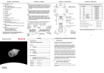
GAS DATA Monitoring the Environment GFM100 Series Analyser User Manual DOCUMENT CONTROL SHEET GFM100 Series User Manual Issue A, Revision 0 Issue Date: 28/11/06 Copy No: 1 Copy Holder: Archive User guide to the operation of the GFM100 series of portable carbon dioxide analysers. Issue Description: New manual - November 2006 Revision Description: First release - for proof checking Gas Data Pegasus House, Wheler Road, Seven Stars Estate, Coventry CV3 4LB, United Kingdom Phone +44 (0)24 7630 3311 • Fax +44 (0)24 7630 7711 GFM100 Series\43.0\A\0 GFM100 Series User Manual.doc Table of Contents Introduction 1 Safety 1 Warranty policy 1 Conditions and exclusions 2 In the case 2 1. Operation 4 1.1. Front panel controls 4 1.2. Connections 4 1.3. Navigating the Operation and Settings screens 1.4. Gas display 1.4.1. Connecting the gas pipe 1.5. Settings 5 6 6 7 1.5.1. Alarm level 7 1.5.2. Pump volume 8 1.5.3. Pump flow rate 9 1.6. Auto Turn Off Maintenance 9 10 2.1 Low Battery warning 10 2.2 Batteries 11 2.3 Factory calibration 11 User calibration 3.1. 12 Navigating the User Calibration screens 12 3.2 Calibration procedure 13 3.3 Reset factory defaults 14 Changing the gas filter 16 i G F M 1 0 0 S E R I E S U S E R M A N U A L Introduction T he Gas Data GFM100 Series Analyser is a portable Analyser designed specifically for monitoring gases in a wide variety of applications including ventilation control and indoor air quality monitoring. It is also suitable for monitoring carbon dioxide in the food, drink and brewing industries. The GFM100 Series typically uses an infra-red carbon dioxide sensor and a mix of electrochemical cells. It is a single channel instrument which can be fitted with either an infra red carbon dioxide cell in various ranges OR a single toxic gas electrochemical cell. The instruments have rechargeable Nickel Metal Hydride batteries giving around 12 hours use between charges. A battery charger and mains unit is supplied with the instrument and a field replaceable battery pack is also available as an optional extra. Safety Under no circumstances should the instrument be used as the sole means of determining whether an area is safe or otherwise for any particular function or application. As the usage of the instrument is entirely out of our control, we cannot accept any liability for loss or damage due to its usage. You should satisfy yourself that the unit is suitable for the application for which you intend to use it. If in doubt about the suitability of the GFM100 Series Analyser for a particular application, please call Gas Data Limited for further advice. Warranty policy This instrument is guaranteed, to the original end user purchaser, against defects in materials and workmanship for a period of one year from the date of shipment to the user. During this period, Gas Data Limited will repair or replace defective parts GFM100 Series \43.0\A\0 1 GFM100 Series User Manual.doc G F M 1 0 0 S E R I E S U S E R M A N U A L on an exchange basis. Freight charged to and from the Gas Data factory or authorised service centre will be paid by the end user. The decision to repair or replace will be determined by Gas Data Limited. Conditions and exclusions To maintain this warranty, the purchaser must perform maintenance and calibration as prescribed in this user guide. This includes prompt replacement or repair of defective parts and such other necessary maintenance, calibration and repair as may be required according to the use of the equipment in the reasonable judgement of Gas Data Limited. Normal wear and tear, and parts damaged by abuse, misuse, negligence or accidents are specifically excluded from the warranty. In the case The GFM100 Series instruments are supplied in a fitted case containing the following items: GFM100 instrument Allen key Spares kit Gas pipe Battery charger GFM100 Series \43.0\A\0 2 GFM100 Series User Manual.doc G F M 1 0 0 S E R I E S U S E R M A N U A L GFM100 GFM110 GFM130 Common features 1 to 7 gas Single One I/R channel only and up to 2 capability gas channels Carbon dioxide infra red reading range Choose from ONE (1) of the below Choose ONE I/R and UP TO TWO (2) of the below P 0 10000 ppm 0 10% 0 60% 0 100% Expansions available GFM150 IAQ One I/R, 2 extra expansions. Temp & humidity inc. P Choose from UP TO SEVEN (7) of the below NOTE: Only 1 I/R P P P P P P P P P P P O O O Oxygen CO H2S H2S SO2 NO NO2 CL1 HCN NH3 0-25% 0-50 ppm 0-200 ppm 0-1500 ppm 0-20 ppm 0-250 ppm 0-20 ppm 0-10 ppm 0-100 ppm 0-50 ppm P P P P P P P P P P P P P P P P P P P P P P P P P P P P P P P P O O O O O O O O Photo ionisation cell Data storage and download software ATEX certified option 0-2000 ppm isobutylene P O P P O P P P O O P O EXAMPLES GFM100 0-10000ppm CO2: GFM110 0-60% CO2 + 0-25% O2 + Data storage: GFM110 0-100% CO2 + 0-25% O2 + 0-50ppm CO: NOTES GFM100 and GFM110 range available November 2006 GFM130 available January 2007 GFM150 available April 2007 GFM100 Series \43.0\A\0 3 GFM100 Series User Manual.doc G F M 1 0 0 S E R I E S U S E R 1 M A N U A L Section Operation 1.1. Front panel controls 1. X. This key allows you to scroll through the various screens and view expansion channels. It also doubles as a scroll and +/- key which is used in conjunction with the OK key to set alarm levels. 2. OK. Press and release: The instrument will run the pump until the programmed sample volume has been taken - see Sections 1.5.2 Pump volume and 1.5.3 Pump flow rate. Press and hold: The pump will run continuously until the OK key is pressed again. Press and hold while switching on: The instrument will enter calibration mode. 3. Power ON/OFF. This key simply toggles the instrument on or off. Under battery power, the instrument will automatically turn itself off if no key is pressed for 10 minutes. The instrument backlight is automatically switched on when this key is pressed. 1.2. Connections Communications port (optional) Sample out (optional) Battery charger socket Sample in GFM100 Series \43.0\A\0 4 GFM100 Series User Manual.doc G F M 1 0 0 S E R I E S U S E R M A N U A L 1.3. Navigating the Operation and Settings screens GFM100 Series \43.0\A\0 5 GFM100 Series User Manual.doc G F M 1 0 0 S E R I E S U S E R M A N U A L 1.4. Gas display After you have switched the instrument on, the display screen will first show the start-up banner, which contains details of the instrument model, serial number and recalibration date. The display will change after a few seconds to show the main gas readout. At this point the display will show the current carbon dioxide (CO2) reading. If the optional gas channels are fitted, one will be shown on this screen. 1.4.1. Connecting the gas pipe Connect the flexible plastic gas pipe from the probe to the Sample In port on the top of the GFM100 instrument. This will press in and ‘click’. If it will not enter easily press the metal button on the side of the port and try again. The port will automatically lock the pipe in place, preventing it from being pulled off accidentally. Press the metal button on the side of the port to release the pipe. Insert the pipe into the test area then press and release the OK key to start the pump for a period determined by the pump volume and flow rate settings – see Section 1.5. When the pump is running the instrument will take a reading of the carbon dioxide present in that area. If fitted with expansion cells, it will also measure the concentration of other gases. To stop the pump, press and release the OK key again. If you wish to run the pump continuously, press and hold the OK key until you hear a beep. To stop the pump, press and release the OK key – see Section 1.1 Front panel controls. Press the X key to move to the next screen, which displays the concentration of any other gas if the appropriate expansion cell is fitted. If the cell is not fitted, the screen displays a series of chevrons. GFM100 Series \43.0\A\0 6 GFM100 Series User Manual.doc G F M 1 0 0 S E R I E S U S E R M A N U A L 1.5. Settings The GFM100 Series enables you to set a number of parameters by using a series of setting screens. To enter this setting sequence, press and hold down the X key while the instrument is displaying the main gas reading screen. This will open the alarm level screen. Settings are stored in non-volatile memory, so each time you turn the instrument on the settings you used previously will still be valid. 1.5.1. Alarm level This screen enables you to set the gas levels at which the alarm sounds. For all gases except oxygen the alarm will sound if the gas level exceeds the alarm setting. For oxygen the alarm will sound if the gas level falls below the alarm setting. The first screen shows the alarm setting for carbon dioxide (CO2) with a highlight around the reading. To the right of the highlighted setting is an arrow pointing UP. If you press the X key, the arrow changes to point DOWN. When the arrow points UP, press the OK key to increase the alarm level setting; when the arrow points DOWN, press the OK key to decrease the alarm level setting. If you wish to disable the alarm, enter a zero in the highlighted area. Once you have the CO2 alarm setting you want, press the X key. This will open the next gas channel alarm setting screen. Set the alarm level for this channel in exactly the same way as for CO2. Again, the first screen has the arrow pointing UP. Press the OK key to increase the setting. To decrease the setting, first press the X key to invert the arrow then press the OK key to decrease the setting. If you wish to disable the alarm, enter a zero in the highlighted area. GFM100 Series \43.0\A\0 7 GFM100 Series User Manual.doc G F M 1 0 0 S E R I E S U S E R M A N U A L When this channel is at the level you require, press the X key again. This will open the next gas channel alarm setting screen. Set the alarm level for this channel in exactly the same way as for the previous two channels. Again, the first screen has the arrow pointing UP. Press the OK key to increase the setting. To decrease the setting, first press the X key to invert the arrow then press the OK key to decrease the setting. If you wish to disable the alarm, enter a zero in the highlighted area. Press the X key again to open the final gas channel alarm setting screen. Once again, the first screen has the arrow pointing UP. Press the OK key to increase the setting. To decrease the setting, first press the X key to invert the arrow then press the OK key to decrease the setting. If you wish to disable the alarm, enter a zero in the highlighted area. This completes the gas alarm level setting sequence. Press and hold the X key to move to the pump volume setting sequence. 1.5.2. Pump volume This enables you to set the required size of the gas sample in ml that you wish the instrument to take. The display screen shows a highlight around the volume setting. NOTE: For this to work correctly the ‘pump flow rate’ setting must also be correct – see Section 1.5.3 below. As with the gas alarm settings, the first screen has an arrow pointing UP. To increase the setting, press the OK key. If you want to decrease the setting, first press the X key to invert the arrow so that it points DOWN, then press the OK key to decrease the setting. GFM100 Series \43.0\A\0 8 GFM100 Series User Manual.doc G F M 1 0 0 S E R I E S U S E R M A N U A L When you have the pump volume setting you require, press and hold the X key again. This will take you to the pump flow rate setting. 1.5.3. Pump flow rate This setting is used to calculate the length of time the pump will need to run to take the set ‘pump volume’ of gas. The display screen shows a highlight around the pump flow reading. The setting should be set to the pump flow value given on the calibration certificate supplied with the instrument. The default value is 300 ml/min. As with the gas alarm settings, the first screen has an arrow pointing UP. To increase the setting, press the OK key. If you want to decrease the setting, first press the X key to invert the arrow so that it points DOWN, then press the OK key to decrease the setting. When you have the pump flow rate setting you want, press and hold the X key. This will return you to the main gas reading screen. 1.6. Auto Turn Off To help conserve battery life, the GFM100 Series features an auto power off facility. This ensures that the instrument will switch itself off after 10 minutes if no keys are pressed. GFM100 Series \43.0\A\0 9 GFM100 Series User Manual.doc G F M 1 0 0 S E R I E S U S E R M A N U A L 2 Section Maintenance 2.1 Low Battery warning A series of horizontal bars of different lengths at the left-hand side of the display screen indicates the state of charge of the rechargeable batteries. Pump on indicator Battery condition indicator When all the bars except the shortest have disappeared, it is time to recharge the batteries or replace them with another battery pack. If the batteries become completely exhausted the instrument will flash a message ‘Low battery’ and will then automatically switch off a short time afterwards. Make sure the batteries receive a full recharge. To recharge the batteries, simply plug in the battery charger lead to the socket on the top end of the instrument and plug the charger into the mains. The batteries will be fully charged in about three hours. GFM100 Series \43.0\A\0 10 GFM100 Series User Manual.doc G F M 1 0 0 S E R I E S U S E R M A N U A L 2.2 Batteries The GFM100 Series uses rechargeable Nickel Metal Hydride cells. To change the batteries, remove the two screws on the rear of the instrument, then lift the battery cover and remove the battery pack from the recess. Place the new battery pack in the recess, making sure that the metal contacts on the battery pack are placed face down on the spring contacts in the base of the battery box. Replace the battery cover and secure with the two screws. Always replace the battery pack in dry, clean conditions, preferably indoors. NEVER allow dust or moisture to enter the battery compartment. Do not use excessive force on the battery cover fixing screws. Make sure the rubber seal is correctly in place. If you replace the batteries in the field, you can, of course, recharge them later when you return to base. If the instrument is to be stored for more than four weeks, ensure that the batteries are fully charged. After four weeks, charge the batteries again. However, if the instrument does not operate after prolonged storage, the batteries have become discharged and will be unable to ‘fast charge’. They will, therefore, need a longer charge time. 2.3 Factory calibration The instrument is supplied with a calibration certificate. It is recommended that the instrument is returned to Gas Data Limited once a year for service and recalibration. User calibration adjustments can be carried out at any time by following the instructions in Section 3 User Calibration. GFM100 Series \43.0\A\0 11 GFM100 Series User Manual.doc G F M 1 0 0 S E R I E S U S E R M A N U A L 3 Section User calibration 3.1 Navigating the User Calibration screens GFM100 Series \43.0\A\0 12 GFM100 Series User Manual.doc G F M 1 0 0 S E R I E S U S E R M A N U A L The GFM100 Series has an extensive user calibration facility. You can adjust any of the gas channels in a sequence of operations using a known calibration gas for each channel. 3.2 Calibration procedure To enter the calibration mode, press and hold the OK key when you switch the instrument on. As soon as the start-up banner appears, release the OK key. After a few seconds the initial calibration screen will appear. Select the gas channel you wish to calibrate by repeatedly pressing the X key until the appropriate gas appears at the bottom right of the screen. Next, press the OK key. This will open a screen that asks you to choose whether to have the pump running or not. Typically you would have the pump running to set an air point (e.g. 0.038% CO2, 20.95% O2 for clean fresh outdoor air), and not running if using bottled gas. Press the X key to start the pump or the OK key to leave it switched off. You will then enter the calibration screen which shows the current calibration level. If you wish to calibrate, press the either the X key or the OK key to continue. If you want to skip calibration, press X and OK simultaneously. GFM100 Series \43.0\A\0 13 GFM100 Series User Manual.doc G F M 1 0 0 S E R I E S U S E R M A N U A L A highlighted setting appears to the right of the current calibration level. This is the concentration of the calibration gas you are applying. To enter a gas calibration point, flow the calibration gas through the instrument until the reading on the left stabilises. Set the calibration point by using the X and OK keys to adjust the right-hand reading to match the concentration of the of the calibration gas. X decreases the reading; OK increases the reading. When you have set the calibration gas point, press both the X and OK keys together. You will now be asked whether or not you want to update the calibration. Press the X key to accept the calibration point you have just entered, or the OK key to discard the point – see Section 3.3 Reset factory defaults. Press the X key to return to the Pump On/Off screen described above so that a second calibration data point can be set on this gas channel. OR Press the OK key to finish the calibration. The result of the calibration will be displayed. The words on the right indicate the action taken. The possible actions are: No Change - no calibration points entered. Offset - a single data point was entered and accepted in the range, the instrument’s offset has been recalculated so that the calibration point is now correct. Calibrated - two data points were entered in the range. The instrument has been able to calculate a new offset AND span factor. Press either the X key or the OK key to return the instrument to the gas readings mode. This will display the main gas reading screen. 3.3 Reset factory defaults You can return to the factory set defaults at any time. To do this, first press and hold the OK key while you switch the instrument on. Release the OK key when the start-up banner appears. GFM100 Series \43.0\A\0 14 GFM100 Series User Manual.doc G F M 1 0 0 S E R I E S U S E R M A N U A L The start-up banner will remain on screen for a few seconds then change to the initial calibration screen. Select the gas channel you wish to return to the factory default by repeatedly pressing the X key until the appropriate gas appears at the bottom right of the screen. Now press the OK key. This will take you to the Pump On screen. Press the OK key to leave the pump switched off. You will now enter the Calibration screen. Press the X and OK keys simultaneously to move to the Update Calibration screen. Press the OK key to skip the update process. This will take you to the Reset screen. Press the X key to reset the factory defaults for the gas channel. The screen will then change to the More Points screen. Press the OK key to skip this step and the Summary screen appears. Finally, press either the X key or the OK key to return to the main gas reading screen. GFM100 Series \43.0\A\0 15 GFM100 Series User Manual.doc G F M 1 0 0 S E R I E S U S E R M A N U A L 4 Section Changing the gas filter WARNING: NEVER use the GFM100 without the correct filter. There is a gas filter built into the input of the instrument. Check this filter weekly and change it when it becomes clogged or dirty. Always use the correct filter of the recommended type, which can be supplied by Gas Data Limited. If you use a nonrecommended filter, this will invalidate the warranty on the instrument. To replace the filter, first remove the four screws around the base of the Sample In port. Lift the top off the port and remove the old filter. Insert a new filter, making sure to orientate it correctly, replace the top of the port and secure with the four screws. Do not use excessive force on the filter housing fixing screws. DO NOT USE THE INSTRUMENT WITHOUT A CLEAN FILTER FITTED. GFM100 Series \43.0\A\0 16 GFM100 Series User Manual.doc