1
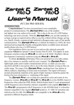
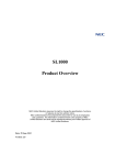
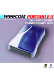
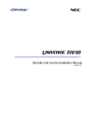
MyCalls Call Recorder Installation Manual Version 1.3 for Sense 2.6.2 Table of Contents MyCalls Call Recorder................................................................................................ 3 Call Recording Licensing ..................................................................................................................... 4 Background on ISDN Call Recorders .................................................................................................. 5 Requirements....................................................................................................................................... 6 Compatibility of Sense and MyCalls .................................................................................................... 7 Installation .................................................................................................................. 8 Connecting The ISDN Call Recorder. .................................................................................................. 8 Connecting an Analogue Call recorder ................................................................................................ 9 SIP Trunk Recording ........................................................................................................................... 9 Installing the Call Recording Software ............................................................................................... 10 Manually Installing the USB Driver .................................................................................................... 20 Using Sense ............................................................................................................. 24 Configuring Recording of SIP Trunks ................................................................................................ 25 Manually Pausing Recording Using DTMF Digits.............................................................................. 27 Installing a License for Manual Pausing ....................................................................................... 27 Configuring Manual Pausing the Feature in Sense ...................................................................... 27 Auto Deletion of Calls ........................................................................................................................ 29 Upgrading from Older versions of Call Recording Software .............................................................. 29 Disabling Encryption on the ‘TMP’ Folder ......................................................................................... 30 Keeping Calls for a Fixed Period ....................................................................................................... 31 MyCalls Configuration .............................................................................................. 32 Netlink and Call Recording ................................................................................................................ 36 Configuring Call Recording Rules...................................................................................................... 37 Call playback users and groups......................................................................................................... 38 Playing back calls .............................................................................................................................. 40 Archiving Recorded Calls .................................................................................................................. 41 Local Archiving................................................................................................................................... 41 Archiving to a Networked Location .................................................................................................... 42 Backup Folder .................................................................................................................................... 42 Volume Names .................................................................................................................................. 43 Manual Call Recording Archiving Using MyCalls .............................................................................. 44 Scheduled Archiving .......................................................................................................................... 45 Exact Channel Mapping ........................................................................................... 46 Single PRI Unit................................................................................................................................... 46 Single BRI Unit................................................................................................................................... 48 Single Analogue Unit ......................................................................................................................... 48 SIP Trunk Call Recording .................................................................................................................. 48 Multiple Units ..................................................................................................................................... 49 Multiple PRI Units .............................................................................................................................. 50 Multiple Analogue / BRI Units ............................................................................................................ 52 Firmware on the Call Recording Box ........................................................................ 53 Checking The Firmware Version ....................................................................................................... 53 Upgrading the Firmware .................................................................................................................... 54 MyCalls Call Recorder MyCalls Call Recorder gives you the ability to record and playback trunk calls made on an SV8100 / SL Series PBX. The call recording software can record ISDN, SIP and analogue trunk calls. For ISDN calls, a recording unit is placed between the Network Termination Equipment (NTE) and the physical card in the PBX. There is a USB lead on the call recording unit that is connected to a PC. As calls pass through the call recording unit, they are streamed onto the PC and stored in a database. SIP trunk calls are recorded by connecting a ‘mirrored port’ carrying SIP traffic to a network card in the call recording server. The SIP trunk information presented by the mirrored port will allow the SIP trunk information to be recorded and stored on the call recording server. Once a call has finished, it is compressed, encrypted and stored ready for playback. MyCalls Call Recorder gives users the ability to find and playback these recorded calls using the MyCalls application. MyCalls version 3 and above has different licensable options that are available for call recording. P Commands / SMDR PRI MyCalls PC USB Lead Print Server Power/TX Link/Rx LPT1 LPT2 COM Call Recorder PSTN MyCalls Database Recorded Calls Database This manual covers the procedure for installing MyCalls call recorder on the SV8100 PBX and the SL series PBX. The installation procedure is the same for both PBX’s but the SL series PBX does not have Primary rate call recording available. Call Recording Licensing MyCalls Call Recorder requires MyCalls Call Manager or above to work. The MyCalls licenses and the call recording license should be installed on the SV8100 / SL and read from the SV8100 / SL using the license manager. The license will have to be registered once it has been read from the SV8100 / SL, further details on licensing are available in the MyCalls installation manual. The call recording licensing options can be reviewed once the license has been installed in MyCalls in the Help / About screen in the MyCalls application. Included with the MyCalls Call Recorder comes the standard player. Two further licenses can be purchased to enable more features, details features are shown below. Waveform Display Sound Clips Section Marker Single Call Recording Export Bulk Call Recording Export Volume, Balance, Playback Speed Call Audit Standard Enhanced*1 Enhanced and Audit *2 *1 MyCalls Enhanced Player is part number EU100021 for SV8100 and EU300025 for SL Series, License Code 7152. *2 MyCalls Call Playback Auditing is part number EU100022 for SV8100 and EU300026 for SL Series, License Code 7153. This license requires the enhanced player to be installed. There is a separate licensable option for the call recording unit that allows recording to be paused using DTMF tones. This license has to be installed on the physical call recording box and isn’t visible in the MyCalls application. Background on ISDN Call Recorders There are two types of ISDN call recorders that are available, a USB 1.1 unit and a USB 2 unit. The instructions in this manual are for the USB 2 Unit, for information about the USB 1 unit, refer to the SV8100 MyCalls v1 installation manual. It is not possible to use a mixture of USB 1 and 2 units on the Sense call recording PC. To identify which version a unit is, look at the front of the call recording unit. Note that different software is required depending on which type of unit you are installing. The picture below shows a USB 1.1 unit. The difference between the two units is that the USB 1.1 unit has a USB connector on the front of the unit. Note the USB port on the left hand side of the unit. The picture below is of USB 2 unit. Note that the front USB connector is blanked out and not available. Requirements SV8100 MyCalls Software 2.5.0.0 SP3 / SL MyCalls 3.5.1.0 or greater. Sense Call Recording Software version 2.6.2 Firmware version 2.4.1 (June 2010). Sense 2.6.2 is only supported on the SV8100 / SL series PBX Refer to the specific MyCalls installation manual for any system software version requirements. The call recording server must be a dedicated PC for call recording. If you are recording 30 channels or greater then MyCalls and the call recording software must be on separate PC’s. Access to the call recording server PC should be made secure by a username and password. Limiting the number of users that have access to the PC is also considered an extra security precaution. A maximum of 120 channels can be recorded on a single call recording server. If you are recording more than 120 channels, then two call recording servers can be used. When implementing a call recording solution, consideration should be given to backing up recorded calls. Details on how to backup recorded call are provided later in the manual. For optimum performance of call recording the operating system of the PC and Sense should be installed on different drives. Minimum Hardware Specification – MyCalls and Sense on the Same PC.* Intel Dual Core 2.0GHz Processor 3GB RAM Min 500GB of available Hard Disk Space *MyCalls and Sense can only be on the same if less than 30 channels are being recorded. Minimum Hardware Specification – Sense Only Upto 60 chanells being recorded. Intel Dual Core 2.0GHz Processor 3GB RAM Min 1TB of available Hard Disk Space Minimum Hardware Specification – Sense Only Up to 120 chanells’ being recorded. Intel Quad Core Processor 8GB RAM Min 1TB of available Hard Disk Space Operating systems: Windows XP Pro min SP2 – 32 BIT only Windows Server 2003 SP2 – 32 BIT only Windows Vista Business, Ultimate and Enterprise 32 BIT only Windows 7 Professional, Ultimate and Enterprise 32 and 64 BIT Windows Server 2008 R2 64 BIT A sound card and speakers are required for call playback Note although MyCalls is supported on Terminal Services and Hyper V, the call recording software is not. Call playback using a MyCalls client is not supported in a thin client environment. 1GB of disk space will store approximately 100 hours of call recordings, depending on requirements it may be necessary to increase the available disk space in the PC. Recorded calls can be archived to free up space from the PC. There must be an available USB port for each call recorder that will be connected to the PC. The USB ports that the call recording units connect to must be USB 2 Ports and not USB 1.1. USB web cams or USB video devices should not be connected to the same USB controller as the call recording units. Additional USB controller cards can be installed if required. Compatibility of Sense and MyCalls Sense 2.6.2 uses a stronger, more complex ‘SA’ password that is different to what was in previous versions of Sense. The password previously used was a weaker password and could potentially halt the installation package if a password policy had been implemented on the PC sense was being installed on to. MyCalls has to be aware of this password for when it is playing back calls from the sense database. If a site is upgraded from an older version of Sense to 2.6.2 then it will keep on using the same weaker SA password as before. For that reason Sense 2.6.2 can only be used with MyCalls 2.5 and above, for versions 2.5 and 3.0 service packs have to be installed in order for MyCalls to use the strong password. For MyCalls 2.5, service pack 3 or above should be installed and for MyCalls 3.0 service pack 1 or above should be used. The services packs must be applied to the MyCalls server and client. MyCalls 2.5 SP3 and 3.0 SP1 are both compatible with the strong and weak passwords so can be used with any version of Sense. Installation Connecting The ISDN Call Recorder. The call recording unit can be rack mounted, free standing or mounted in a CD ROM bay of a PC. The patch leads connecting through the tap connector should each be no longer than 5 metres in length. The USB lead supplied with the call recording unit is 1 metre in length. This will mean the call recording until and PC will have to be situated near each other. The ISDN lines are connected from the NTE into the tap connector supplied with the call recording unit. A cable should then run from the other socket on the tap connector to the ISDN card in the PBX. Once both are connected, calls will be able to pass through the tap connector. There are different types of tap connectors, one for BRI and one for PRI. The PRI is black and the BRI is white, both are clearly labelled and can only be used on their respective call recorder. Once the lines are connected through the tap connector, the other two cables labelled in and out should be connected to the front of the call recording unit accordingly. Securely connect the supplied power adapter to the call recording unit and firmly connect the supplied USB lead to the rear of the call recording unit. Connect the USB lead to the PC until before installing the call recording software. If the operating system starts the new hardware found wizard, click cancel. Tap Connector PSTN In Out Print Server Power/TX Link/Rx LPT1 LPT2 COM Call Recorder Connecting an Analogue Call recorder The Analogue call recorder has a different power supply to the other call recording units, ensure that the correct power supply is attached to the analogue call recording box. The analogue call recorder wiring should be connected by tapping into the line and presenting the two wires to an RJ45 socket on the front of the call recording unit. A lead is provided that will connect from a standard LJU (BT Style) socket to the front of the call recording unit. The BT socket is also re-presented so that the line can be connected to a PBX. The image below shows a standard LJU socket with the supplied lead connecting from the LJU to the call recording unit. The socket indicated by the red arrow is the socket that can be connected to the PBX. This will need repeating for each line that will be recorded. Should the cables that are provided not be suitable then the two wires provided by the carrier will need to be connected to pins 4 and 5 of an RJ45 socket that is connected to the front of the call recording unit. SIP Trunk Recording SIP trunk recording doesnt require any physical hardware to be installed, it instead uses packet sniffing technology to record calls. Both G.711 and G.729A codes are supported for SIP recording, other codecs cant be recorded. A port mirror from a network device carrying the SIP trunk calls has to be connected to a network card in the call recording server. The network card in the call recording that will perform the packet sniffing must support promiscuous mode. Promiscuous mode will allow a network card to pass packets that are not addresed to it allowing the calls to be recorded. Depending on the device performing the the port mirror, it may be neccesary to have a second card in the call recording server to capture the SIP packets. The port mirror can be placed in two different locations depending on the configuration of the network and how the IP trunks are presented to the SV8100 / SL. If there is a dedicated internet circuit provided for the SIP trunks, then the port mirror would be best placed on the port uplinking the router to the LAN. The port mirror can also be placed in-line with the IPL card of the SV8100 / SL, this will capture all traffic passing through the IPL. The only draw back to using this method is that IP extension calls will be recorded too. As MyCalls doesnt report on internal calls then any internal calls cant be played back using MyCalls. This would also mean if an IP extension made a call on an SIP trunk there would be two calls recorded. Installing the Call Recording Software The call recording software is referred to as the Sense Software or Call Recording software and is supplied with each call recording package. Before you can install the software, you will need to extract the software to the PC you intend on installing Sense onto. Begin the installation by double clicking the Call Recorder Main Installation icon. Sense can be installed on a different PC to MyCalls. If you are installing on Windows Vista or Windows 7, you may get a prompt in a window titled User Account Control. To allow the installation to continue, click yes when prompted. At the beginning of the install, if you are prompted to install a Hotfix for Windows Media Encoder, click yes to install the Hotfix. The installation will begin, click next to continue. There are some prerequisites that have to be met before the installation can begin. If the Windows Installer 4.5 is installed during the installation then the PC may need to be restarted before you can continue. WinPcap is installed during the installation of the call recording software. This is a component of the SIP recording software. Complete the installation wizard for WinPcap and then the Sense installation will continue. At the collecting information screen, select Install Server and Client and click Next. On the next step of the installation wizard, there are two options to choose from, workgroup or domain. When live calls are being recorded, they are placed in a folder called the ‘tmp’ folder on the call recording server. Encryption can be enabled on this folder so that while calls are stored in the tmp folder, they are encrypted. If the PC is part of a Windows Domain then the EFS certificate issued to the tmp folder can either become randomly invalid or after 3 years of being issued expire. During the install, if you select Workgroup then encryption of the tmp folder will be enabled. By selecting Domain, encryption on the tmp folder will be disabled. To prevent the possibility of any potential problems with encryption on the tmp folder, select Domain during the install. By selecting this option, the final audio files are always encrypted before they are available for playback. Encryption on the tmp folder can be disabled manually, details are available later in the manual. At the License Agreement window, read the license agreement. To continue, click ‘I accept the license agreement’ and click next. Choose a folder where the Call recording software will be installed to and click next. At the next prompt you can select where the tmp folder is located. The Audio Storage folder can then be selected, this is the folder where the compressed and encrypted final audio files are stored. Typically the audio storage folder can take up large amounts of disk space so if a separate disk has been made available for storing the audio files on, it should be selected here. At the backup folder prompt, click next. This is a feature of the call recording software that is not used. With MyCalls Call Recorder backups and archiving are carried out through the MyCalls application, not the call recording software. At the SQL Server Root Folder screen, choose which folder the back-end MyCalls database will be installed to. This folder is just where the Call Recording database sits, not where the audio files for the recorded calls are stored. Select the folder as required and click next. During the install, if an USB box is connected to the call recording server, the USB driver will be installed. On Windows Vista and Windows 7 you will be prompted to allow the driver to be installed, when you see the window below, click OK. On other operating systems, the driver is installed silently without the need for any interaction. At the Windows Security prompt, select install this driver software anyway. After the Call Recording Software has been installed, the call recording client has to be installed. The client is the application that is used by the call recording software to view recorded calls. Choose which folder the client should be installed to and click next. After the client installation has completed the ‘Options’ screen will be displayed. Click cancel to allow the installation to finish. The options can be configured at a later time. Click finish when the installation has completed. Now the installation has completed, calls will be recorded and stored in the call recording database. If the PRI / BRI / Analogue boxes are being used and the USB leads were connected to the call recorder before the software was installed then the USB drivers will have been installed automatically. To check that the devices are installed correctly, look in device manager and under USB_NEC Recorder make sure there is an entry for each unit that is connected. Manually Installing the USB Driver To install the driver manually for call recording unit, first connect the USB lead from the call recording unit to the PC. The found New Hardware Wizard will start. Select No, not this time and click next. Select install from a list or specific location (Advanced) and click next. Select ‘Include this location in the search’ and click browse Browse to the folder with contains the USB driver. The USB driver is contained in the \bin\Thesyscon folder underneath where the call recording software was install to. The default location is ‘C:\Program Files\NEC\NEC Recorder\bin\Thesyscon’ The folder location the driver will be installed from will be displayed. At this point click next. The driver for the unit will then be installed. Upon completion, click finish. Once the installation of the USB device and recording software is complete, the USB/Serv status light will change green. If you are connecting multiple units then you will have to repeat the procedure to install the driver for each unit. Using Sense To Login to Sense, click the ‘Calls’ shortcut from the desktop of the call recording server. The default username is ‘admin’ and password ‘callrecorder’. When logged into Sense, you will see a list of calls that have been recorded and some details about the calls. To playback a call using Sense, double click on the call from the list and it will be played back. This is usually done using the MyCalls interface but it maybe neccesary to review the call list in Sense to confirm call recording is working as expected. Its important to establish with SIP calls that the direction of the call is correct, SIP calls can be identified as being listed with ‘Box’ number 129 and as having a comment stating the codec used for the call. If the direction of SIP calls show incorrectly, then it may be necessary to review the VoIP call recording configuration. Its possible to make calls and click the refresh button in Sense, this will allow you to see live call information to verify call recording is working. Live calls are highlighted in yellow in Sense. Configuring Recording of SIP Trunks SIP trunk recording requires some configuration in Sense to allow the calls to be recorded. In the Sense application, click Tools, Options and on the Special page in the network devices section select the network card connected to the port mirror. The Mac Address of the selected network card, will be displayed under the Network Devices Window. Once the network card has been selected click on the VoIP tab. In the LAN box, enter a LAN mask for the local network being used multiple entries should be separated by commas. The default options, for example 10.255.255.255 will cover all devices on a 10.x.x.x network, 192.168.1.255 would cover all devices on a 192.168.1.x network. Also in the LAN box, enter the public IP address of the internet connection used by the IP trunks. This is usually the Public IP Address of the router connected to the internet or the device configured as the NAPT router. In the TSP Gateways box, enter the IP address of the SV8100 / SL and the IP address of the SIP carrier, separate entries with a comma. The call recording software will use these IP addresses to determine the direction of the calls. In the example below, the port mirror is connected to a network card in the PC using the following network configuration: IP Address 10.0.0.10, Subnet 255.0.0.0, Default Gateway 10.0.0.1 Using a LAN Mask of 10.255.255.255 will allow communication from an address using a 10.x.x.x address. The public address that the internet connection is using is 91.85.64.251. The IP address of the SV8100 / SL in this setup is 10.0.0.100 and SIP carriers address is 81.200.220.123. These are the two IP entries in the TSP Gateway box. After making any changes click the save button. To apply the changes, the call recording service has to be restarted, this would mean that any calls that are currently being recorded will not be recorded. If you click No then the changes will be saved but will not be applied until the service is restarted. The service can be manually restarted from the File menu in Sense. Manually Pausing Recording Using DTMF Digits. Manual pausing of call recording using DTMF digits can be implemented on an ISDN call recording solution, pausing isn’t available on Analogue on SIP recording. Pausing is a licensed feature and there is a separate license that will allow pausing from the PBX side and the outside caller. The purpose of the feature is to allow sensitive information not to be recorded. When enabled, the feature will detect a defined sequence of DTMF and stop / start recording during a call. A time-out value can also be configured so that if a recording is paused it will automatically start recording again after a set number of seconds. When the DTMF stop or start commands are instigated both parties will hear the DTMF digits being sent to line. Whilst the recording is in a stopped state, the call continues to record as normal but silence is recorded in it until it starts recording again. A programmable function key can be put on a digital keyset to dial the DTMF digit to send the digits for stop / start recording. This Feature is not available in all territories, please check with your account manager for availability. This feature requires Sense Software 2.6.2 and Firmware March 2011 (2.6.2). Instructions for upgrading the firmware are available in the Firmware on the Call Recording Box section of this manual. The firmware is made available once an order is placed for the feature. To use the feature a license as to be installed on the call recording box, there are two licenses available for manual pausing as follows: License Code Description EU000221 MyCalls Call Recorder Manual Pausing PBX Side. This allows a user on the PBX side of the call to pause recording by dialling DTMF digits. EU000222 MyCalls Call Recorder Manual Pausing Caller Side. This allows the external caller to dial digits to pause recording. Installing a License for Manual Pausing A license has to be installed on the call recording box in order for the feature to work, if multiple boxes are being used each box will need to have a license installed. The license is tied to the serial number of the call recorder, this means when the license is ordered for the feature, the serial number of the call recorder should be specified. If there is more than one unit, all serial numbers will need to be supplied. A version of firmware March 2011 (2.6.2) containing a license for the DTMF pausing feature will be made available once the order has been processed. The firmware file including the license will be sent via email. The firmware will need installing on the call recording box, see Firmware on the Call Recording Box for further details. Should you experience an issue installing the license, please contact your reseller for techncial support. Configuring Manual Pausing the Feature in Sense To configure the pausing feature in Sense, you will need to login to the Sense application. In the Sense application, select the tools / options menu and then click the Server tab and scroll down to the PCI Compliance section. Set the Detect DTMF command option to true, this will enable the feature. The other options can be set as required, any DTMF digits must be preceeded with a ‘# ‘or a ‘*’, details of each option are in the table below. Option Function Detect DTMF commands Set to ‘True’ to enable the feature or false to disable it. DTMF Detection interval (seconds) The number of seconds between dialling the first and last digits to pause recording. If the DTMF digits are spread over a longer interval, the sequence will not be detected. The max value is 15 seconds. Restart recording timeout Set the maximum duration not to record in seconds. When recording has been paused it will automatically restart after this timer expires. If the value is set to 0 then recording will only restart when the start command is sent again. Start Recording command (Agent) This is the DTMF sequence to start recording again after it has been stopped. Enter # or * and a digit(s) as required, this action is recognised by a user on the PBX. Start Recording command (Customer) This is the DTMF sequence to start recording again after it has been stopped. Enter # or * and a digit(s) as required, this action is recognised by the outside caller. Stop Recording command (Agent) This is the DTMF sequence to stop recording. Enter # or * and a digit(s) as required, this action is recognised by a user on the PBX. Stop Recording command (Customer) This is the DTMF sequence to stop recording. Enter # or * and a digit(s) as required, this action is recognised by the outside caller. To save and apply the settings, click OK. The call recording service will need to be restarted to apply the setting. When the service is restarted, and calls that are being recorded at that time will not be available for playback. Auto Deletion of Calls By default ‘Auto Deletion’ of calls that have not been archived or backed up is turned on inside the Sense software. When the hard disk of where the data folder is located gets down to 10GB of disk space remaining it will start to delete older calls from the call recording server. This clears space for new calls on the PC and will stop the hard disk from becoming full. If a call has been Auto deleted then it is permanently deleted and cannot be recovered. This feature can be turned off by logging into Sense and from the Tools menu, select Options. On the Server tab, expand Audio post processing and set ‘On low disk space, delete none archived calls to ‘False.’ Click OK to save the changes and you can choose if you restart the service to apply the changes. If there are any active calls while the service is restarted then they will not be available for playback. If the Auto Deletion is turned off then calls will have to be archived to prevent the hard disk from becoming full. Full detail on how to carry out archiving using the MyCalls application is provided later in this manual. Upgrading from Older versions of Call Recording Software To upgrade from Sense 2.3.4.737 to any other version, you will just need to extract the new version of software that will be installed. Without un-installing the old version, start the installer of the new version. The software will be upgraded automatically using the existing file structure. To upgrade from older versions of Sense i.e. pre 2.3.4.737 then you will need to remove the old software first. In Control Panel / Add and Remove Programs, remove the existing Sense applications and then start the installation of the new software. During the installation, select the required folders for the different areas of the application as described in the ‘Installing the Call recording software’ section of this manual. Disabling Encryption on the ‘TMP’ Folder When live calls are being recorded, they are stored in the ‘TMP’ folder on the call recording server. Depending on which options are selected during the install, the TMP folder may be encrypted (further details are available in the ‘installing the call recording software’ section of this manual. To check or disable encryption on the TMP folder, find the Data folder and right click the ‘tmp’ folder then select Properties. In the properties window, click the advanced button in the lower right hand section. In the Advanced Attributes windows, un-check the ‘Encrypt contents to secure data’ option and click OK to save the changes. Keeping Calls for a Fixed Period Some businesses may only want to keep call recordings for a fixed period of time i.e. one month or 1 year. This option can be configured in the Sense application under the Archive > Scheduled Archives menu. WARNING. Calls that are deleted by the scheduler are permanently deleted from the call recording server. Once deleted the will not be available for call playback even if they have been archived. Click ‘Add Deletion’ and you are able to create a schedule to keep the number of days of call recordings as required. In the first line, enter the number of days of recording you want to keep. In the schedule date, enter the first time the schedule should be run and the time it should be run at. In the repeat section, select how often it is run. The example shown above will delete calls over 90 days older starting at 23:00 on the 22/2/2011. Every day after at 23:00 any calls over 90 days will be deleted again. This schedule will continue to run until it is deleted. MyCalls Configuration The following instructions are based around MyCalls Version 4 and above. In older versions of MyCalls the call player is different, transfer leg navigation isn’t available and there are no options to configure exported call recording files and default file format. Before you can configure MyCalls to use call recording, you must have a call recording license installed. On the SV8100 / SL this is usually installed on the SV8100 / SL and read into MyCalls. Refer to the MyCalls installation manual for further details. The licensing is broken down into on a per trunk and per trunk type basis. If you have 4 Analogue trunks, 8 PRI trunks and 8 SIP trunks, then trunk types have to be correctly set in MyCalls. To look at the configured trunk types, login to MyCalls and click Configure > Telephone System > Devices > Trunks. For each trunk number, the trunk type can be specified using the drop down menu. SIP trunks should be specified as TCP/IP trunks. To enable MyCalls to playback recorded calls, run the MyCalls application, if you have any users configured you must login to the application as a PBX administrator. From the menu, click Configure / Telephone system, select the PBX you are configuring recording, select Call Recording and click Edit Call Recorder Configuration. In the Edit Call Recorders window, click Add Call Recorder. By adding a recorder you are telling MyCalls about a PC that is running the call recording software. That PC can have several recorders attached to it. Select Retell from the drop down menu and enter a meaningful name for the recorder then click ok. The call recorder will be listed in the Installed Call Recorder section. In the lower Trunk Licensing section, click the Call Recorder field next to each trunk and select the call recorder that will be associated with that trunk. To license each trunk for call recording, you will need to enable the check box in the licensed column. To check or change the trunk type, click Configure / Telephone System / PBX’s / PBX / Devices / Trunks / Create or Edit. Any trunks that are not licensed will not be recorded. Once the trunk licensing is configured, click the edit button next to the recorder that was added in Installed Call Recorders. Enter the name of the PC that has the call recording software installed and click Test Connection. If the test is successful then MyCalls can communicate with the call recording database. Click ok to clear down the message. Click OK twice to save the call recording configuration. If there is an error displayed saying there is a Database connection error, this means that MyCalls can see the Sense database but can’t login to it. This is usually caused by the MyCalls service pack not being installed. If you see this error, check that MyCalls 3.0.0.0 SP1 or MyCalls 2.5.0.0 SP3 has been installed to the MyCalls server and any clients. Netlink and Call Recording When MyCalls is used with Netlink, there needs to be the appropriate MyCalls licenses installed on the SV8100. A Netlink Node license should be installed for each remote Secondary system. When Netlink is used over a number of remote sites and call recording is required, a physical call recording unit will have to be installed at the remote site. The call recorder and software would be installed as normal and then MyCalls has to be configured to be aware of the remote call recorder installation. In the call recording configuration, multiple recorders can be added to the list of installed call recorders. Once all of the recorders have been added, you can click the edit button and configure each call recording server. In the Trunk Licensing section, click on the drop down menu for each trunk and assign it to the appropriate call recorder. Configuring Call Recording Rules To exclude certain types of calls from being recorded, click the Recording Rules button in the call recorder configuration screen. Extensions, DDI’s, Callers, Trunks and Users can all be included or excluded from being recorded as required. Add devices to the selected list and choose ‘Do Not record the selected devices’ or ‘Only record the selected extensions.’ You can also decide if to include incoming only, outgoing calls only or both. Call playback users and groups By default if no users are created in MyCalls, you will be able to playback calls. Once you create any users, you must login to the MyCalls application as a user. When creating users, an Administrator account should be created. Any users that are created and want to play back calls, the users must be enabled for call playback. In Configure / Organisation click create new user or edit an existing user. To give a user the ability to playback calls, check the ‘Enable Call Playback’ box, to allow users to be able to export call, check the ‘Enable Export of Recordings’ and click OK to save any changes. It is also possible to setup hierarchal type permissions to allow certain users to only playback calls from their group. In the example below, the highest level group is called group 1 and in that group, there is a user call Supervisor. The user supervisor can playback any calls from any calls associated to Group 2 and Group 3. The user Group 2 Supervisor can only playback calls in the group named group 2. The same principle applies to the user Group 3 Supervisor, it can only playback calls for users in group 3. For the Hierarchal user structure to work correctly, the users must be assigned to extensions. To assign a user to an extension, go to configure / telephone system and edit an extension. Click edit against the extension you wish to assign to a user Click the select button to choose a user. You can begin to type in the user name to lookup and names stored in the MyCalls database. Select the user and click OK. Playing back calls From the view menu, select Call Records View. By default the call records view will display the last 50 calls for the current day. Calls that have been recorded will show a speaker icon meaning they have been recorded. To play a call that has been recorded, double click the speaker icon on the call record. After you have double clicked the speaker, the player will load and play the call. The screenshot below is of the enhanced player. For further information on using the call player, refer to the MyCalls end user guide, chapter 7. Archiving Recorded Calls Archiving of recorded call is necessary in order to create backups of recorded calls and to prevent the hard drive on the call recording server from becoming full when auto deletion of turned off. With autodeletion turned off, the call recorder will keep on recording calls until there is 10GB of available disk space remaining on the PC. When there is 10GB of disk space remaining the call recording software will start to delete the oldest recorded calls that have been archived. If archiving has not been configured, then when the PC gets down to 2GB of space remaining, it will stop recording. Archiving can be carried out to either a local area on the call recording server or to a UNC (Network Path) that is accessible from the call recording server. If configured, MyCalls can inform you via an email if the backup ever fails. Should a user attempt to playback a call that has been archived and subsequently deleted, MyCalls will prompt for the media that it was archived on to the be inserted. Archives can be run either manually or can be scheduled to run automatically. Archiving is configured in MyCalls > Configure > Telephone System > Call Recording > Edit Call Recorders > Click Edit against the Call Recorder name > Recording Backup. Local Archiving Different types of media can be used for calls to be archived on to. The media used to archive on to should be local to the PC that is running Sense. So long as the operating system can access the drive and perform a copy and paste to the archive drive, the archive procedure should work fine. The purpose of these archives is to stop the hard disk from running out of space. As part of a disaster / recovery type situation, a backup of these archives should be made and stored in a suitably secure location. Media DVD RAM Mass Storage Device Other removable media solutions Overview Needs to have a DVD RAM drive installed. Single sided DVD RAM disks can store up to 4.7GB of data so ideal for lower call volume. Once the disk has been removed from the PC it can be safely stored away until needed. If the disk is stored away correctly and safely, there is little chance of it ever becoming damaged. The DVD RAM drive and disks are relatively inexpensive to buy. Copies of the archives on the DVD RAM disks can be easily made and stored offsite. Examples of Mass storage devices are USB Memory keys or external USB Hard drives. The size of these volumes can be in excess of 500GB so can hold large amounts of data. Using a device with a large storage capacity will need to be changed less often but will increase the vulnerability of the data on the drive. If the mass storage device should fail for any reason and the data was not recoverable then any calls that needed to be played from this device would be inaccessible. As you are dealing with typically larger amounts of data it can also take longer to create off site backups. For example a drive can sit inside a PC and archives could be carried out to a media in that drive. Once that media is full, it can be ejected and replaced with another. Different capacities drives can be used based upon call volume and give a compromise in storage space between DVD RAM and a typical Mass Storage Device. Any archiving that takes place is always relative to the call recording server. If MyCalls and the call recording software are on separate PC’s then the backup media should be connected to the call recording server and not the MyCalls PC. MyCalls instructs the call recording software to perform a backup. Archiving to a Networked Location Its possible to perform archiving to a network location accessible via a UNC* on the Sense Server. This will allows calls to be archived to a central server that could already be backed up as part of a another backup routine. This works in a Windows Domain environment and Sense has to be configured with the Domain name, user name and password that has access to the UNC. These credentials should be entered in Tools > Options > Server in the Archiving section. When the archive begins, these credentials are used to connect to the UNC. *Only UNC’s are supported and not mapped drives. After saving the settings, the Recording Service will have to be restarted. Backup Folder The backup folder is the location from the call recording server that archives will be carried out to. This will be either the local folder accessible on the call recording server or the UNC of the PC that the calls will be archived to. The two example below show a local folder on the call recording server ‘E:\BACKUPS’ and a UNC ‘\\SERVER\BACKUP’. Volume Names When archives are configured to run, a backup volume name has to be entered. This backup volume name is appended to the backup folder name that is specified. If an archive was carried out for example for all call recordings in August 2008 then the volume name for that backup should be identified as something like Aug08. The media that is used should be labelled as volume Aug08. If a call that is archived on to this media and had been deleted from the Sense PC and a user requests to play it, MyCalls will prompt for the media Aug08 to be inserted. When an archive media becomes full, it should be removed from the Sense PC. The administrator should then get the new media ready and decide on the new volume name. The volume name should be changed in the Backup Volume Name section of the Backup Call Recordings configuration page. The media should be the labelled with the new name and inserted in the Sense PC. The Maximum Volume Size can also be configured, the Maximum Volume Size is the size a volume will grow to before its name is changed. For example the settings show in the screenshot below would firstly backup to e:\backups\Jan08.0000 once the folder jan08.0000 reached a size of 1000MB, another folder would be created called e:\backups\Jan08.0001 and this process will keep incrementing every time the folder reaches 1000MB in size. The purpose of this is to stop the number of files contained in the volumes becoming too high. Manual Call Recording Archiving Using MyCalls A manual archive can be instigated using the MyCalls backup facility. From the Configure / Telephone System / PBX select Call Recording and edit the call recorder configuration. From the call recorder configuration screen, click the Recording Backup button. In the ‘Backup Folder on Recording Server’ enter the path and folder that the backups should be archived to. Enter a name for the Volume of the backup. Select the Start Date / Time and End Date / Time and click the Backup button to start the backup procedure. If any errors are encountered during the backup, they will be displayed in the MyCalls application. A progress indicator will be displayed as the backup is carried out, to abort the backup operation, click cancel. Scheduled Archiving Scheduled archiving can be used to automate the archiving procedure. To enable a scheduled archive, select ‘Schedule a Backup of all Un-Backed up Calls’ and from the Schedule Task drop down menu choose how often the archive should run. In the Start Time, enter the date the schedule should run from and the time it should run at. If any errors are encountered during the archiving procedure they will be reported in the audit login in MyCalls. An email address can be entered so that when any errors are generated, they can be emailed out to the backup administrator. In order for the email notifications to work the Email Server Settings should be configured in the Configure / System Settings / Email Server menu. After setting up any scheduled backups, click ok twice to save the new configuration. Once a media is replaced, it is good practice to change the backup volume name in the in the call recording configuration. Exact Channel Mapping MyCalls uses a best effort matching system to tag calls in the recorded calls database with calls in the MyCalls database. In some circumstances MyCalls cannot guarantee to correctly match the correct call in the two databases. In order to get around this problem Exact Channel Mapping can be used. Exact Channel Mapping is recommended for sites that take a large number of calls on one particular DDI or where multiple Call Recording units are used. Exact Channel Mapping works by each trunk number in MyCalls being mapped to its corresponding ISDN channel number. Where multiple call recording units are being used, each unit must be given a unique ID (CSID.) Where exact channel mapping is used and configured correctly, the match rate will be 100% accurate. If it is incorrectly setup all calls will be incorrectly matched. Single PRI Unit When a single PRI unit is being used you need to assign a Unit ID, Port number and Channel Number to a Trunk Number in MyCalls. Unless multiple units are being used, the unit ID will always be 0. The port number is always the same as the channel number. With Primary Rate ISDN the Channel Numbers run sequentially from 0-29, channel 0 will be trunk 1, channel 1 will be trunk 2 and so on. In MyCalls go to the Configure / Telephone System / Edit PBX and edit the Call Recorder configuration. Click the Assign button next to trunk 1 and assign Unit ID to port 0 and channel 1. The following table shows how to configure the other trunks. SV8100 / SL Trunk Number 1 2 3 4 5 6 7 8 9 10 11 12 13 14 15 16 17 18 19 20 21 22 23 24 25 26 27 28 29 30 Unit ID Port ISDN Channel 0 0 0 0 0 0 0 0 0 0 0 0 0 0 0 0 0 0 0 0 0 0 0 0 0 0 0 0 0 0 0 1 2 3 4 5 6 7 8 9 10 11 12 13 14 15 16 17 18 19 20 21 22 23 24 25 26 27 28 29 0 1 2 3 4 5 6 7 8 9 10 11 12 13 14 15 16 17 18 19 20 21 22 23 24 25 26 27 28 29 Configure all the trunks as required and click OK to save the changes to the recorder configuration, then OK to save the changes to the PBX configuration. Once configured, you should make a call on each trunk to make sure the exact Channel Mapping is working as expected. Single BRI Unit The same concept applies to Basic rate, with a single BRI unit to assign a Unit ID, Port number and Channel Number to a Trunk Number in MyCalls. Unless multiple units are being used, the unit ID will always be 0. The port number is always the same as the channel number. With Basic Rate ISDN the Channel Numbers run sequentially from 0-7, channel 0 will be trunk 1, channel 1 will be trunk 2 and so on. SV8100 / SL Trunk Number 1 2 3 4 5 6 7 8 Unit ID Port ISDN Channel 0 0 0 0 0 0 0 0 0 1 2 3 4 5 6 7 0 1 2 3 4 5 6 7 Single Analogue Unit Assuming the trunk numbers run sequentially from 1-8 then the channel mapping would be configured as follows. SV8100 / SL Trunk Number 1 2 3 4 5 6 7 8 Unit ID Port Channel 0 0 0 0 0 0 0 0 0 1 2 3 4 5 6 7 0 1 2 3 4 5 6 7 SIP Trunk Call Recording In order to use channel mapping with SIP Trunk call recording, you must have SV8100 R4 software or above installed on the SV8100. Slightly different to the way channel mapping works on ISDN recording, when a call SIP call is made, the trunk number that the call is made on is stored in the Sense database. MyCalls can then match calls using the trunk number is was made on. SIP calls always has a fixed Unit ID of 129 that cant be changed. If many SIP trunks are connected to one call recording PC then then unit ID will always be 129 and the Port and Channel will always be the same as the trunk number. Some examples are shown below: SV8100 / SL Trunk Number 1 2 50 51 140 141 Unit ID Port Channel 129 129 129 129 129 129 1 2 50 51 140 141 1 2 50 51 140 141 Multiple Units When using multiple units, the same concept applies to the Channel Mapping for each trunk on the PBX. The only difference is each Call Recording unit must be given a unique ID; this would usually be 0, 1, 2, or 3 as applicable. By default each unit comes with unit ID 0. The following procedure describes how to change the ID of a Call Recording unit. 1. Unplug the USB leads for all Call Recording units and plug in the unit that you want to set the ID on. 2. Leaving the lines connected through the TAP connector, disconnect the ‘In’ and ‘Out’ connectors from the front of the call recording unit. 3. Browse into the Sense installation folder and then into the ‘BIN’ sub folder. In there, double click the ‘Stop Service’ shortcut. A black window will appear and then automatically close down when the service is stopped. 4. In the ‘BIN’ folder, double click on the VPS application to view the current CSID, type in ‘show’ and press enter 5. Scroll up in the Windows looking under the system information and look at the line starting 106. The value to the right is the current CSID. 6. To change the CSID, type “set 106 n’ where n is the ID you wish to assign to the unit. 7. Type ‘store’ to save the new CSID in the unit. 8. In order for the new ID to become active, the unit has to be rebooted. To reboot the unit either type reset and press enter or re-power the unit. 9. While the unit powers up again, reconnect the ‘In’ and ‘Out’ sockets on the front of the call recording unit. 10. Repeat this procedure for each call recording unit that you need to configure. 11. When finished, plug in all the units and double click the ‘Start Service’ shortcut in the ‘BIN’ folder. Multiple PRI Units A maximum of 4 PRI units can be installed with MCCR. Each unit must be given a unique CSID’s from 0-3. This example assumes the PBX has 4 primary rate cards installed with the trunk numbers running sequentially from 1-120 SV8100 / SL Trunk 1 2 3 4 5 6 7 8 9 10 11 12 13 14 15 16 17 18 19 20 21 22 23 24 25 26 27 28 29 30 31 32 33 34 35 36 37 38 39 40 41 42 43 44 45 46 47 48 49 50 51 Unit ID 0 0 0 0 0 0 0 0 0 0 0 0 0 0 0 0 0 0 0 0 0 0 0 0 0 0 0 0 0 0 1 1 1 1 1 1 1 1 1 1 1 1 1 1 1 1 1 1 1 1 1 Port 0 1 2 3 4 5 6 7 8 9 10 11 12 13 14 15 16 17 18 19 20 21 22 23 24 25 26 27 28 29 0 1 2 3 4 5 6 7 8 9 10 11 12 13 14 15 16 17 18 19 20 Channel 0 1 2 3 4 5 6 7 8 9 10 11 12 13 14 15 16 17 18 19 20 21 22 23 24 25 26 27 28 29 0 1 2 3 4 5 6 7 8 9 10 11 12 13 14 15 16 17 18 19 20 52 53 54 55 56 57 58 59 60 61 62 63 64 65 66 67 68 69 70 71 72 73 74 75 76 77 78 79 80 81 82 83 84 85 86 87 88 89 90 91 92 93 94 95 96 97 98 99 100 101 102 103 104 105 106 107 108 109 1 1 1 1 1 1 1 1 1 2 2 2 2 2 2 2 2 2 2 2 2 2 2 2 2 2 2 2 2 2 2 2 2 2 2 2 2 2 2 3 3 3 3 3 3 3 3 3 3 3 3 3 3 3 3 3 3 3 21 22 23 24 25 26 27 28 29 0 1 2 3 4 5 6 7 8 9 10 11 12 13 14 15 16 17 18 19 20 21 22 23 24 25 26 27 28 29 0 1 2 3 4 5 6 7 8 9 10 11 12 13 14 15 16 17 18 21 22 23 24 25 26 27 28 29 0 1 2 3 4 5 6 7 8 9 10 11 12 13 14 15 16 17 18 19 20 21 22 23 24 25 26 27 28 29 0 1 2 3 4 5 6 7 8 9 10 11 12 13 14 15 16 17 18 110 111 112 113 114 115 116 117 118 119 120 3 3 3 3 3 3 3 3 3 3 3 19 20 21 22 23 24 25 26 27 28 29 19 20 21 22 23 24 25 26 27 28 29 Multiple Analogue / BRI Units A maximum of 6 BRI or 6 Analogue units can be installed with MCCR. Each unit must be given a unique CSID’s from 0-5. This example is for the first 3 units and it assumes that the trunk numbers running sequentially from 1-24. SV8100 / SL Trunk 1 2 3 4 5 6 7 8 9 10 11 12 13 14 15 16 17 18 19 20 21 22 23 24 Unit ID 0 0 0 0 0 0 0 0 1 1 1 1 1 1 1 1 2 2 2 2 2 2 2 2 Port 0 1 2 3 4 5 6 7 0 1 2 3 4 5 6 7 0 1 2 3 4 5 6 7 Channel 0 1 2 3 4 5 6 7 0 1 2 3 4 5 6 7 0 1 2 3 4 5 6 7 Firmware on the Call Recording Box Sense requires the correct level of firmware to be installed on the call recording unit. Sense 2.4.1 is only compatible with Firmware June 2010 (2.4.1). Sense 2.6.2 is compatible with Firmware June 2010 (2.4.1) and March 2011 (2.6.2). If the firmware running on the box is older than June 2010, then it should be upgraded to firmware June 2010 (2.4.1.) The firmware is available to download from ftp://ftp.neci.co.uk/mycalls/sense If you have been issued firmware March 2011 (2.6.2) for the DTMF pausing feature, then this can be installed using the instructions below. Checking The Firmware Version To establish what firmware a recorder is running, on the call recording server the locate the \bin folder and double click the ‘Stop Service’ icon a black window will appear and then close down. Now double click the vps.exe icon, a black window will appear and the firmware version is displayed in the lower section of the vps window. Note: On a Windows 7 Operating system, you have to right click the Stop Service icon and select ‘Run as Administrator.’ If the firmware version is from any date in 2008, then there is an extra step required to perform the upgrade. If there are multiple units attached to a PC then the firmware version for each box should be checked individually. To select a box, type ‘SDD 0’ to select the first box detected by the PC, you will see a confirmation in the lower section of the vps window that you are on box 0. To view the firmware version on the box, type ‘reset’ and press enter, the box will restart and the firmware version will be displayed. To switch to the next box, type ‘SDD 1’ the box can be restarted in the same way to see the firmware version running on the box. The SDD number can be incremented by 1 each time to check the firmware version on each box connected to the PC. On a PC with 4 call recorders connected to it, the firmware would have to be checked for SDD 0, SDD 1, SDD 2 and SDD 3. Alternatevily, the USB leads can be disconnected from the PC leaving the box connected that is being checked. Upgrading the Firmware If the existing firmware is from 2008, then carry out the step 1 below, if the firmware is newer than 2008 then go straight to step 2. Download the correct level of firmware from ftp://ftp.neci.co.uk/mycalls/sense and save it into the root of the c drive (c:\) on the call recording server. If you are carrying out step 1 also copy the file named 2vxBoot.bin into the root of the C drive (c:\) If you are enabling the pausing feature using DTMF then use the firmware files that have been emailed to you. Before you start, make sure the the service is stopped and the VPS window is running, the same way as used to check the firmware version on the box. 1. Make sure the file named 2vxBoot.bin is in the root of the C drive (c:\) and in the vps window type ‘burn boot123’ and press enter. When both of the top two LED’s on the call recording box go green, move to step 2. 2. When the firmware.bin file is in the root of the C drive (c:\) type ‘burn’ in the VPS window. The upgrade will now commence and takes around 1 minute, once completed, you will see ’Download succeeded’ in the vps window. 3. Once you see the Download Succeeded message type ‘reset’ and press enter to reset the box. As the box boots up, you will see the new firmware version displayed in the vps window. If you have multiple boxes each box has to be upgraded in turn. To select the first box, type SDD 0 and upgrade the firmware as above. Once upgraded, select the next box by typing ‘SDD 1’ and carry out the upgrade procedure. Repeat this for each box by incrementing the SDD for each box a required. Once all boxes have been upgraded, double click the start service icon from the \bin folder Document History Feb 2011 Initial release when call recording was separated from MyCalls installation manual. Added Sense 2.6.2 June 2011 Add SL1100 Jan 2012 Add Pausing with DTMF Update Firmware Upgrade Procedure May 2012 Update for MyCalls 3.5.0.0 April 2013 Update for MyCalls 4.0 / SL 3.5 LIABILITY DISCLAIMER NEC Unified Solutions reserves the right to change the specifications, functions, or features, at any time, without notice. NEC Unified Solutions has prepared this document for use by its employees and customers. The information contained herein is the property of NEC Unified Solutions and shall not be reproduced without prior written approval from NEC Unified Solutions. All brand names and product names on this document are trademarks or registered trademarks of their respective companies. Copyright 2012 NEC Unified Solutions NEC Unified Solutions P.O. Box 32 1200 JD Hilversum The Netherlands