1
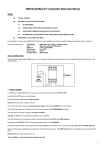
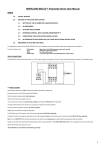
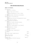
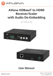
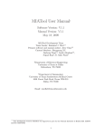
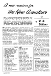
MINISENSOR4-MCU-D™ USER MANUAL INDEX 1.0 INITIAL TESTING 2.0 SETTING UP YOUR APPLICATION 3.0 2.1 SMARTCYCLE™ CONTROL APPLICATIONS 2.2 SINGLE SETPOINT CONTROL APPLICATIONS 2.3 DUAL SETPOINT CONTROL APPLICATIONS 2.4 FULLY PROGRAMMABLE DUAL SETPOINT CONTROL APPLICATIONS 2.5 DUAL SETPOINT SETUP 2.6 COMPLETING YOUR APPLICATION INSTALLATION 2.7 PULSE WIDTH MODULATION OUTPUT APPLICATIONS 2.8 USING OPEN COLLECTOR OR VOLT FREE CONTACT SWITCH SENSORS 2.9 ALTERNATIVE STATUS DISPLAY RETURNING TO FACTORY SETTINGS It is advisable to connect up the MINISENSOR4-MCU- and check/confirm operation before any reprogramming is carried out. The unit is factory set to: LED display Range T1 Input STARTMODE ANALOGUE input status (0 to 100%) Single setpoint, relay and optocoupler outputs ganged and in phase 0 – 10Vdc 0 Outputs active (on) below setpoint INITIAL CONNECTIONS Connect the DC supply and a 0 -10V analogue sensor +ve, 0V and open collector connections to the two 4 way screw terminal blocks as shown in the diagram below: If no 0 – 10V sensor is available use none, one and then two (in series) AA batteries across B1 and B2 terminals in the tests below. 1 1.0 INITIAL TESTING Set the input voltage to zero. Set the setpoint potentiometer fully clockwise. Switch on the DC power supply to the unit. The module will power up with a 2 second startup delay and the green STATUS LED will illuminate. The LED will then blink on (25ms) every 2 seconds to indicate a NO INPUT condition. The relay and OUTPUT2 LED (optocoupler output) will also activate to signal a below setpoint condition. Slowly increase the (0 – 10V) analogue input voltage (one AA battery = 16%). The LED blinking rate will increase to every 0.8 seconds indicating 0 to 20% INPUT detected. Increase the (0 – 10V) analogue input voltage further (two AA batteries = 32%). The LED changes to flashing (0.8 seconds) every 2 seconds indicating 20 to 40% INPUT detected. Slowly turn the setpoint potentiometer anticlockwise until the relay and the OUTPUT2 LED deactivate. The setpoint is now set to slightly less than present analogue input. Switch off the DC power supply to the unit. Remove all four red setup jumper links. The unit is now tested and functioning correctly. 2 2.0 SETTING UP YOUR APPLICATION The MINISENSOR4-MCU-D provides comprehensive single and twin setpoint dual output control features and can be easily configured for your particular application. The green STATUS LED is provided for diagnostic purposes and can be set up to indicate input level or control status. Simply follow the step by step process below to set up your application: 2.1 SMARTCYCLE™ CONTROL APPLICATIONS (T range T4) In this mode the relay and optocoupler outputs implement automatic control sequencing between the lower and upper setpoints. This can be used for maximum/minimum pressure, drain/fill level or in/out position control applications. Skip this section if your application does not require this mode of operation. 2.1.1 Automatic fill cycle mode In this SMARTCYCLE™ mode the relay automatically activates a motor/pump/valve etc to increase the pressure/ level/position and analogue sensor input from the lower setpoint to the upper setpoint. The cycle stops at the upper setpoint and restarts only when the sensor input falls back to the lower setpoint. A typical example is an automatic tank fill application. The table below shows the relay and optocoupler states above and below the setpoints: STARTMODE = 0 < INPUT INCREASING LOWER SETPOINT > ON < UPPER SETPOINT > ON OFF RELAY INPUT DECREASING ON INPUT INCREASING OFF OFF OFF OFF ON OPTO INPUT DECREASING OFF ON ON If this mode suits your application go to section 2.5 DUAL SETPOINT SETUP 2.1.2 Automatic empty cycle mode In this SMARTCYCLE™ mode the relay automatically activates a motor/pump/valve etc to decrease the pressure/ level/position and analogue sensor input from the upper setpoint to the lower setpoint. The cycle stops at the lower setpoint and restarts only when the sensor input rises back to the upper setpoint. A typical example is an automatic tank drain application. The table below shows the relay and optocoupler states above and below the setpoints: STARTMODE = 1 < INPUT DECREASING LOWER SETPOINT > OFF < UPPER SETPOINT > ON ON RELAY INPUT INCREASING OFF INPUT DECREASING ON OFF OFF ON OFF OPTO INPUT INCREASING ON ON OFF If this mode suits your application set STARTMODE =1 Insert the programming plug - facing right - offset, upper (STARTMODE) - onto the vertical left hand 6 pin SET UP header Switch on the power to the unit. The LED will illuminate continuously to indicate STARTMODE = 1 set. Switch off the power and remove the programming plug. Repeat procedure to return to STARTMODE = 0. The LED will blink on continuously to indicate STARTMODE = 0 reset. Switch off the power and remove the programming plug. Now go to section 2.5 DUAL SETPOINT SETUP. 3 2.2 SINGLE SETPOINT CONTROL APPLICATIONS (T range T1) In this mode the relay and optocoupler outputs are controlled by a single setpoint, the setpoint% potentiometer setting. Skip this section if this control mode does not suit your application. 2.2.1 Single setpoint same switching polarity The table below shows the relay and optocoupler states above and below the single setpoint (OUTPUT jumper link left). RANGE T1 < SETPOINT > RELAY ON OFF OPTO ON OFF RELAY OFF ON OPTO OFF ON STARTMODE = 0 STARTMODE = 1 2.2.2 Single setpoint opposite switching polarity The table below shows the relay and optocoupler states above and below the single setpoint (OUTPUT jumper link right). RANGE T1R RELAY ON < SETPOINT > OFF OPTO OFF ON RELAY OFF ON OPTO ON OFF STARTMODE = 0 STARTMODE = 1 Set up the STARTMODE to match your application control states as follows: Insert the programming plug - facing right - offset, upper (STARTMODE) - onto the vertical left hand 6 pin SET UP header Switch on the power to the unit. The LED will illuminate continuously to indicate STARTMODE = 1 set. Switch off the power and remove the programming plug. Repeat procedure to return to STARTMODE = 0. The LED will blink on continuously to indicate STARTMODE = 0 reset. Switch off the power and remove the programming plug. Now go to section 2.6 COMPLETING YOUR APPLICATION INSTALLATION. 2.3 DUAL SETPOINT CONTROL APPLICATIONS (T ranges T2 & T3) In this mode the relay and optocoupler outputs are controlled by a two setpoints, the upper setpoint% and the lower setpoint% set by the setpoint% potentiometer. The relay output is always controlled by one setpoint, the optocoupler output is always controlled by the other setpoint. Skip this section if this control mode does not suit your application. 2.3.1 Dual setpoint, relay output controlled by upper setpoint, optocoupler output by lower setpoint same and opposite switching polarity (T range T2) The table below shows the relay and optocoupler states above and below the setpoints (OUTPUT jumper link left). RANGE T2 < LOWER SETPOINT > < UPPER SETPOINT > ON RELAY ON OPTO ON OFF OFF RELAY OFF OFF ON OPTO OFF ON ON OFF STARTMODE = 0 STARTMODE = 1 4 The table below shows the relay and optocoupler states above and below the setpoints (OUTPUT jumper link right). < LOWER SETPOINT > < UPPER SETPOINT > ON OFF RANGE T2R RELAY ON OPTO OFF ON ON RELAY OFF OFF ON OPTO ON OFF OFF STARTMODE = 0 STARTMODE = 1 Set up the STARTMODE to match your application control states as follows: Insert the programming plug - facing right - offset, upper (STARTMODE) - onto the vertical left hand 6 pin SET UP header Switch on the power to the unit. The LED will illuminate continuously to indicate STARTMODE = 1 set. Switch off the power and remove the programming plug. Repeat procedure to return to STARTMODE = 0. The LED will blink on continuously to indicate STARTMODE = 0 reset. Switch off the power and remove the programming plug. Now go to section 2.5 DUAL SETPOINT SETUP. 2.3.2 Dual setpoint, optocoupler output controlled by upper setpoint, relay output by lower setpoint same and opposite switching polarity (T range T3) The table below shows the relay and optocoupler states above and below the setpoints (OUTPUT jumper link left). RANGE T3 < LOWER SETPOINT > < UPPER SETPOINT > OFF OFF RELAY ON OPTO ON ON OFF RELAY OFF ON ON OPTO OFF OFF ON STARTMODE = 0 STARTMODE = 1 The table below shows the relay and optocoupler states above and below the setpoints (OUTPUT jumper link right). RANGE T3R < LOWER SETPOINT > < UPPER SETPOINT > OFF OFF RELAY ON OPTO OFF OFF ON RELAY OFF ON ON OPTO ON ON OFF STARTMODE = 0 STARTMODE = 1 Set up the STARTMODE to match your application control states as follows: Insert the programming plug - facing right - offset, upper (STARTMODE) - onto the vertical left hand 6 pin SET UP header Switch on the power to the unit. The LED will illuminate continuously to indicate STARTMODE = 1 set. Switch off the power and remove the programming plug. Repeat procedure to return to STARTMODE = 0. The LED will blink on continuously to indicate STARTMODE = 0 reset. Switch off the power and remove the programming plug. Now go to section 2.5 DUAL SETPOINT SETUP. 5 2.4 FULLY PROGRAMMABLE DUAL SETPOINT CONTROL APPLICATIONS (T range T4) In this mode the relay and optocoupler outputs are also controlled by a two setpoints, the upper setpoint% and the lower setpoint% set by the setpoint% potentiometer. Both the relay and optocoupler outputs can be controlled by either setpoint. The relay and optocoupler output states are fully user programmable. To use this feature, switch on the power and wait for the green LED to blink continuously (no input). Wait one second, then switch off the power. User programming is now enabled. Now complete the table below with the relay and opto on/off status for your application and program the unit. RANGE T4 A < LOWER SETPOINT > B < UPPER SETPOINT > C RELAY OPTO Then insert the programming plug - facing right - centralised (MYTIME) - onto the vertical left hand 6 pin SET UP header Rotate the setpoint potentiometer fully anticlockwise & switch on the power. The LED will blink continuously to indicate ready to program. Skip setting 1 Rotate potentiometer fully clockwise, then on the first flash rotate potentiometer fully anticlockwise (BandSetNumber skipped). Skip setting 2 Rotate potentiometer fully clockwise, then on the first flash rotate potentiometer fully anticlockwise (display skipped). ‘A’ sector program relay Rotate potentiometer fully clockwise, then on the first flash rotate potentiometer fully anticlockwise (RELAY OFF). or Rotate potentiometer fully clockwise, then on the second flash rotate potentiometer fully anticlockwise (RELAY ON). ‘A’ sector program opto Rotate potentiometer fully clockwise, then on the first flash rotate potentiometer fully anticlockwise (OPTOCOUPLER OFF). or Rotate potentiometer fully clockwise, then on the second flash rotate potentiometer fully anticlockwise (OPTOCOUPLER ON). ‘B’ & ‘C’ sectors Repeat ‘A’ sector above. The LED will then switch off to indicate programming complete. SMARTCYCLE App erased and replaced by user programmed App. Switch off the power and remove the programming plug. 2.5 DUAL SETPOINT SETUP You now need to set up the relationship between the upper setpoint% and lower setpoint% for your application. The lower setpoint is locked to the potentiometer adjusted upper setpoint. It can be programmed from 5% below the upper setpoint to 90% below the upper setpoint in 1 to 18, 5% steps called BandSetNumbers. The BandSetNumber is factory set to 10. This sets the lower setpoint to 50% below the upper setpoint potentiometer setting. The formula for calculating the BandSetNumber is as follows: BandSetNumber = upper setpoint% - lower setpoint% -------------------------------------------------5 e.g. If your application requires an 83% (of the sensor full scale output) upper setpoint and a 24% lower setpoint (59% below upper setpoint) then the BandSetNumber is 83 - 24 = ----------= 11.8 round up to 12 (60% below upper setpoint) 5 Insert the programming plug - facing right - centralised (MYTIME) - onto the vertical left hand 6 pin SET UP header Rotate the setpoint potentiometer fully anticlockwise. Switch on the the power to the unit. The LED will blink continuously to indicate ready to program. Rotate potentiometer fully clockwise to start counting in the calculated BandSetNumber (12 in the above example). The LED will flash quite slowly for each count. Remember digital counting starts at zero not one. Count the flashes 0,1,2 then on 12 (in the example) rotate potentiometer fully anticlockwise to store 12. Switch off the power and remove the programming plug. 6 2.6 COMPLETING YOUR APPLICATION INSTALLATION The unit is now ready for final set up and installation testing: 1 Check your final BandSetNumber and display set up. Insert the programming plug - facing right - centralised (MYTIME) - onto the vertical left hand 6 pin SET UP header Rotate the setpoint potentiometer fully clockwise. Switch on the power to the unit and wait 3 seconds (STATUS LED on). Rotate the setpoint potentiometer fully anticlockwise. The unit will now automatically count out the BandSetNumber on the LED. Remember digital counting starts at zero not one. So in the above example (12 stored) BandSet digit Count the flashes 0,1,2,3,4,5,6,7,8,9,10,11 & 12 , done. Wait 3 seconds The unit will now automatically count out the DisplaySet on the LED. DisplaySet digit Count the flashes 0 or Count the flashes 0,1 analogue input display set. control state display set. Switch off the power to the unit and remove the programming plug. 2 Setup 4 – 20mA or 0 – 20mA input sensor connections shown below 0 – 20mA operation Select LOOP jumper link out right and skip to 3 below. 4 – 20mA operation Insert the red shorting plug, centralised onto the vertical left hand side 6 pin SET UP header. Switch on the power to the unit. The LED will illuminate continuously to indicate 4 – 20mA input programmed. Switch off the power and remove the red shorting plug. Select LOOP jumper link out right. Repeat procedure, if required, to reset 0 – 10V input. The LED will blink on continuously to indicate 0 – 10V input programmed. Switch off the power and remove the red shorting plug. Select LOOP jumper link in left. 3 Set up T range T1 - T2 jumper link in left, T3 jumper link in left, OUTPUT jumper link in left. T1R - T2 jumper link in left, T3 jumper link in left, OUTPUT jumper link out right. T2 - T2 jumper link out right, T3 jumper link in left, OUTPUT jumper link in left. T2R - T2 jumper link out right, T3 jumper link in left, OUTPUT jumper link out right. T3 - T2 jumper link in left, T3 jumper link out right, OUTPUT jumper link in left. T3R - T2 jumper link in left, T3 jumper link out right, OUTPUT jumper link out right. T4 - T2 jumper link out right, T3 jumper link out right, OUTPUT jumper link in left. 4 DIN rail mount unit. 5 Install the analogue sensor and the power, relay and optocoupler connections. 7 6 Set the setpoint% potentiometer to your application upper setpoint% (e.g. 83%) (Note if a 60% control band has been programmed the lower setpoint% will be 83 – 60 = 23% 7 Switch on the system power and wait one second. 8 Your dual/single setpoint system will now operate as per your setup. 9 The STATUS LED will progress through the sensor input levels for the application. 0 to 20% input blinking on every 0.8 seconds 20 to 40% input flashing on every 2 seconds 40 to 60% input flashing on every 0.8 seconds 60 to 80% input blinking off every 0.8 seconds 80 to 100% input on continuously >100% input triple flash, 4 second flash cycle warning. 10 Adjust the setpoint% potentiometer, if necessary, to optimise the upper setpoint% and lower setpoint% settings for your application. 11 And finally if you wish to protect your set up against unauthorised adjustment: Switch off the power to the unit. Temporarily remove all SET UP jumper links. Insert the programming plug - facing right - offset, lower (LOCKPOT) - onto the vertical left hand 6 pin SET UP header Switch on the power to the unit. The LED will illuminate continuously to indicate setpoint% setting is now locked. Switch off the power and remove the programming plug. Repeat procedure, if required, to unlock potentiometer. The LED will flash every two seconds to indicate potentiometer is now unlocked. Switch off the power and remove the programming plug. Replace all jumper links into their previous positions. 12 Record your final set up details on the configuration label on the side of the unit: Installation is now complete. 8 2.7 PULSE WIDTH MODULATION OUTPUT APPLICATIONS The unit can also be setup to provide a 50Hz, 0 to 100% duty cycle output pulse train representation of the analogue input voltage/current. In this mode the optocoupler is set to PWM output and the relay assigned to a single setpoint. The table below shows the relay and optocoupler states above and below the setpoints RANGE T4R RELAY < ON SETPOINT > OFF OPTO PWM PWM RELAY OFF ON OPTO PWM PWM STARTMODE = 0 STARTMODE = 1 Set up the STARTMODE to match your application control states as follows: Insert the programming plug - facing right - offset, upper (STARTMODE) - onto the vertical left hand 6 pin SET UP header Switch on the power to the unit. The LED will illuminate continuously to indicate STARTMODE = 1 set. Switch off the power and remove the programming plug. Repeat procedure to return to STARTMODE = 0. The LED will blink on continuously to indicate STARTMODE = 0 reset. Switch off the power and remove the programming plug. Set up T range T4R - T2 jumper link out right, T3 jumper link out right, OUTPUT jumper link out right. The PWM signal can easily be converted to a 0 – 10V/ 0 – 1mA analogue output. Note: Output load 0 – 10V > = 1Mohm, 0 – 1mA < = 100 ohm. 9 2.8 USING OPEN COLLECTOR OR VOLT FREE CONTACT SWITCH SENSORS NPN open collector or voltage free contact switch sensors can be used as an alternative to the single analogue sensor in many applications. Configure the system as follows: Adjust the setpoint potentiometer to 75%. Set the BandSetNumber to 10 (50% band) for dual setpoint applications only. Activate LOCKPOT. 2.8.1 NORMALLY OPEN SENSORS The sensors will be open (volt free contact) or off (open NPN collector) when the sensor input is below the lower switching point (e.g. both out of water). AND The sensors will be closed (volt free contact) or active on (open NPN collector) when the sensor input is above the upper switching point (e.g. both in water). 2.8.2 NORMALLY CLOSED SENSORS The sensors will be closed (volt free contact) or active on (open NPN collector) when the sensor input is below the lower switching point (e.g. both out of water). AND The sensors will be open (volt free contact) or off (open NPN collector) when the sensor input is above the upper switching point (e.g. both in water). 10 2.9 ALTERNATIVE STATUS DISPLAY FOR YOUR APPLICATION INSTALLATION After you have completed and tested your application (including PWM feature, if required) you may wish to change the diagnostic status display indication. The factory set status display provides an indication of the present input%. The status display can be changed to indicate the present control state: NO INPUT LED blinking on every 2 seconds INPUT < lower setpoint LED blinking on every 0.8 seconds INPUT > lower setpoint and < upper setpoint LED on continuous (dual setpoint applications) INPUT > upper setpoint LED flashing on every 0.8 seconds INPUT > 100% LED triple flash, 4 second flash cycle warning Remove all SET UP jumper links. Insert the programming plug - facing right - centralised (MYTIME) - onto the vertical left hand 6 pin SET UP header Rotate the setpoint potentiometer fully anticlockwise and switch on the power to the unit. The LED will blink slowly to indicate ready to program. Skip setting 1 Rotate potentiometer fully clockwise, then on the first flash rotate potentiometer fully anticlockwise to activate factory setting 1. Must now be reprogrammed. The LED will fast blink to indicate ready to program. Rotate potentiometer fully clockwise to start counting. The LED will flash quite slowly for each count. Remember digital counting starts at zero not one. Display set digit Count the flashes, 0 then on 1 rotate potentiometer fully anticlockwise: CONTROL DISPLAY PROGRAMMED. Switch off the power and remove the programming plug. Note: To return to ANALOGUE INPUT DISPLAY, repeat procedure and count the flashes, on 0 rotate potentiometer fully anticlockwise: ANALOGUE INPUT DISPLAY RE-PROGRAMMED. NOW SKIP BACK TO SECTION 2.5 (DUAL SETPOINT SETUP) TO REPROGRAM YOUR UPPER SETPOINT% AND LOWER SETPOINT% LEVELS. 11 3.0 RETURNING TO FACTORY SETTINGS When you start using the programmable features in the unit you can if necessary return to the factory settings and start again. Simply: Remove all SET UP jumper links. Rotate the setpoint% potentiometer fully clockwise. Insert a red jumper link - vertically - centralised - onto the vertical left hand 6 pin SET UP header Switch on the power to the unit. The LED will either illuminate continuously to indicate 4 – 20mA input programmed. or The LED will blink on continuously to indicate 0 – 10V input programmed. Rotate the setpoint% potentiometer fully anticlockwise to switch off the LED. Rotate the setpoint% potentiometer fully clockwise. The LED will flash on/off continuously to indicate RESET ACTIVATED Rotate the setpoint% potentiometer fully anticlockwise. The LED will illuminate continuously to indicate FACTORY SETTINGS restored. Switch off the power, remove the programming plug and restore jumper links to their factory set positions. Tempatron: Eltime House, Hall Road, Maldon, Essex, CM9 4NF UK. Tempatron Industrial Controls is a division of Eltime Ltd. © Eltime Ltd. Tempatron MINISENSOR4-MCU-D User Manual 01/2014 12