1
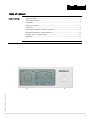
065379 • Version 1.1 • 06.03.2013
HRC 2
User manual
Rev. 1.1
en
1
Der tages forbehold for trykfejl og ændringer
2
Dantherm can accept no responsibility for possible errors and changes
Irrtümer und Änderungen vorbehalten
Dantherm n’assume aucune responsabilité pour erreurs et modifications éventuelles
Table of content
Table of content
Table of content .................................................................................................. 1
General description .............................................................................................. 4
Installation .......................................................................................................... 5
Display information ............................................................................................. 6
User menu ........................................................................................................... 7
Operating information, without accessories. ....................................................... 12
Operation information, with accessories ............................................................. 14
Installer menu / installer mode .......................................................................... 16
065379 • Version 1.1 • 06.03.2013
Appendix ........................................................................................................... 22
3
General description
Introduction
This remote control is designed for the particular and considerate houseowner, who is
especially keen to provide a pleasant indoor climate in his house and to its occupants.
The remote control communicates wireless with the control panel of the ventilation unit
up to a range of 30 meter through walls and lightweight floors.
The remote control can be placed on the shelves or it can be hung on the wall in the
kitchen or in the sitting room. Hereby the occupants of the house can look after the indoor comfort and easily adjust the mode of operation if necessary.
Functions
The following functions can be controlled/activated with the remote control:
•
Automatic demand-control based on relative humidity, or CO 2 (accessory)
•
Manual operation
•
Week program mode
•
Away mode
•
Night mode
•
Temperature control - heat, (only possible with after heating coil which is an
optional accessory)
•
Temperature control – BYPASS-COOLING, by means of built-in bypass
•
Adjust filter change intervals
On the remote control the user can read off the following:
•
Fan step
•
Outdoor temperature, supply air temperature (into the house), exhaust air temperature (from the house) and room air temperature (measured in the remote
control)
•
Day of the week and hour
•
Relative humidity in the exhaust air duct (the humidity of the house)
•
CO 2 level in the house (only possible with an extra CO 2 sensor which is an op-
tional accessory)
4
•
Remaining filter time
•
Alarms + acoustic beeper
Installation
Pairing
The remote control has to be paired with the ventilation unit before use. Follow the procedure below to pair the wireless remote control with the ventilation unit: (communication is between the control panel (HCP4) and the remote control (HRC2))
Step
Action
1
Disconnect the power to the ventilation unit
2
Open the battery lid on the remote control and insert the batteries (2 x AAA)
3
If you want a fixed power supply you can connect a mini-USB cable with pow-
which are included with the remote control.
er supply (accessory). The mini USB-plug is situated behind the battery door
on the back of the remote control.
4
Reconnect the power to the unit. The unit and the remote control now try to
connect with each other for the next 60 seconds and when connection is
made, data from the unit are shown on the display.
If pairing is not successful the first time (display shows E13), this maybe because the
distance between the remote control and the unit control panel (HCP4) is too big, or the
remote control has already been paired with another ventilation unit. In that case, reset
the remote control by pressing down the LEFT part of the navigation key for 10 sec.,
until all icons are flashing. Then a new pairing can start.
Several remote con- It is possible to connect up to 5 remote controls to one ventilation unit. All connected
remote controls are equal. This means that the latest change of operation or setpoints
overrules the previous change, if any.
065379 • Version 1.1 • 06.03.2013
trols
5
Display information
Display
overview
OPERATING PROGRAMS
INFO LINE HOUR/DAY
Display description
OPERATING INFORMATION
FAN SPEED
NAVIGATION BUTTON
The following table describes the symbols and buttons on the remote control.
The remote control has an energy saving function which switches off the display between 23:00 and 7:00. It can, however, be switched on by pressing one button.
Display area
Operating programs
Function
Automatic operation/demand-control
Manual operation mode
Week program mode
Away mode
Night mode
Hour / Day
Info line
The clock is used to control week program mode and
night mode.
Alarm
Information about various functions and programs
Battery low
Fan step
Navigation button
Operating instructions
Four oval fields indicating current fan speed
The button is used to activate the user menu, navigate between menu points, and reduce or increase values.
Shows information about:
• Filter change
• Room temperature
• Supply/extract air temperature
• Outdoor temperature
• Relative humidity in the extract air from the house
• CO 2 level in the air (accessory)
• Heat recovery / bypass-cooling
6
User menu
User menus
Navigation button
In the USER MENU you will find the following operating programs and operating info:
Button
Function
Activates the user menu, a menu point or confirms settings by pressing the
CENTER button.
Navigates between menu points by pressing LEFT or RIGHT on the navigation button.
Reduces or increases values by pushing UP or DOWN on the navigation
button.
Short cuts
Brug
navigationstasten som beskrevet i skemaet
herunder:
Button
Function
Press CENTER for 3 seconds = back to start, leave all menus
Press DOWN for 5 seconds = activate/deactivate bypass-cooling for 6
hours (BYP6)
Press UP for 5 seconds = activate/deactivate fireplace mode for 15 min.
(FP15)
065379 • Version 1.1 • 06.03.2013
Press RIGHT for 10 seconds = activate/deactivate installer menu / installation mode. (only for trained users/installers)
Press CENTER + UP for 10 seconds = back to factory setting of all settings
and setpoints. (Only works in the installer menu)
Press LEFT for 10 seconds = reset pairing
Continued overleaf
7
User menu, continued
Operation programs On the remote control you can choose among different operation modes allowing you to
control the ventilation in accordance with different demands.
Symbol
Description
Demand-control
In AUTO mode the unit adjusts automatically between fan step 1 - 3, so
that the air change matches the actual demand in the house. The unit tries
to maintain a comfortable air quality, measured in relation to the relative
humidity and the CO 2 level (CO 2 control is accessory). In case of high hu-
midity in the air the ventilation demand is increased and the unit adjusts
to fan step 3. In case of low humidity the unit goes down to fan step 1.
The CO 2 control adjusts the unit to step 4 in case of a high CO 2 level.
Manual operation
In Manual mode the user must adjust the fan step manually each time the
air change requirement changes. Fan steps from 0 to 4 are available. Step
0 and 4 are only active for 4 hours, after that time the unit returns automatically to step 3.
Week program
In Week program mode the unit supplies a variable air exchange which is
adapted to the selected family profile (P1, P2, P3 etc.) See the list at the
back of this manual.
The week program number is changed in the following way:
Step
Action
1
When the week program icon is activated (the symbol flashes) the
2
Press DOWN, and the chosen week program No. flashes (for ex-
3
Press UP/DOWN to choose another week program No. and finally
actual week program number is shown below the clock.
ample P1)
press CENTER to confirm the new week program No.
AWAY
The AWAY mode can be activated in periods where the house is unoccu-
pied and when there are no activities requiring air change. In AWAY mode
the unit runs at minimum air change, i.e. 2/3 of the time at fan step 1 and
1/3 of the time at fan step 0. All other functions are working normally incl.
heating and cooling coils, if connected. To deactivate this function press
CENTER, otherwise it deactivates automatically after 28 days and it automatically goes back to the previous operation mode.
Warning!
Remember to deactivate the AWAY mode as soon as the house is occupied
again. Otherwise the house may be damaged as well as comfort for the
people is compromised.
8
Night mode
In Night mode the unit runs at fan step 1, and this mode functions together with Auto, Manual or Week program mode.
Start and end time for night mode are set in the following way:
Step
Action
1
When night mode is activated (symbol flashes) press DOWN and
2
Set start time by pressing UP/DOWN, confirm by pressing CEN-
3
Set the end time by pressing UP/DOWN, confirm by pressing
the start time is shown in the info line (flashes).
TER, and then the end time is shown in the info line.
CENTER. The start and stop time for night mode are now set.
Night mode is deactivated by pressing CENTER, while the icon is flashing.
Afterheating
If afterheating is connected (accessory) it can be adjusted in accordance
with one or more of the following 3 principles:
T2) Afterheating for comfort supply air:
If afterheating is only required to prevent supply of cold air or draught inconvenience, the T2 supply air temperature can be used as setpoint and
regulation temperature. (Factory setting +18°C)
T3) Afterheating for heating of the house:
If afterheating is used as primary heat source for the whole house, T3 extract air temperature can be used as setpoint and regulation temperature.
(Factory setting = OF, meaning that heating is not regulated after this setpoint)
T5) Afterheating for heating of the house or rooms:
If afterheating is used as primary heat source for the whole house and/or
specific rooms, T5 temperature measured in the remote control can be
used as regulating temperature in the room where it is placed. (More re-
mote controls can be connected) (Factory setting = OF, meaning that heating is not regulated after this setpoint)
(T5/SET)
(T3/SET)
(T2/SET)
065379 • Version 1.1 • 06.03.2013
afterheater icon
NB: If all three afterheater setpoints are “OF” the afterheater is OFF.
9
Follow this procedure to set the afterheater setpoints:
Step
Action
1
Activate the menu line by pressing CENTER
2
Press RIGHT to navigate to afterheater icon. The afterheater
icon flashes slowly (30/min). Simultaneously T2, T3 and T5
continue to show the real temperatures in the unit.
3
Press CENTER to navigate to the AFTERHEATER menu.
The display shows the latest settings of all three setpoints (T2,
T3, T5) on their respective places. OFF means that the afterheater is not controlled in accordance with this setpoint.
4
Press CENTER.
The afterheater setpoint for T2 flashes quickly (120/min), and
the afterheater icon flashes.
5
Press UP/DOWN to set the afterheater setpoint T2, and confirm
6
T3 afterheater setpoint now flashes quickly (120/min) and the
by pressing CENTER.
afterheater icon flashes.
Press UP/DOWN to set the afterheater setpoint T3, and confirm
by pressing CENTER.
7
T5 afterheater setpoint now flashes quickly (120/min) and the
afterheater icon flashes.
Press UP/DOWN to set the afterheater setpoint T5, and confirm
by pressing CENTER.
8
The afterheater setpoints are now set and the afterheater icon
on the display flashes slowly (30/min) and all temperatures on
the display are again real measurements in the unit.
9
Press CENTER for 3 seconds to leave the menu.
Clock
Week programs and night mode are controlled by means of the clock. The
clock is set as follows:
Step
Action
1
Press CENTER to activate the menu line (the active op-
2
Press the RIGHT button until the hands of the clock
3
Press DOWN and then UP/DOWN to set the time. Con-
eration mode flashes)
are flashing.
firm by pressing CENTER, then the week day icon
flashes
4
10
Set the week day by pressing UP/DOWN, and confirm
by pressing CENTER
Fire-place Fireplace function
function
FP
The fireplace function is designed to create overpressure in the house, so
that the fireplace can be lit without problems. The overpressure is created
by stopping the extraction and maintaining the supply at fan step 3.
The function is activated/deactivated by pressing UP for 5 seconds, then
FP15 is shown in the INFO LINE = fireplace mode for 15 min. It now counts
down (FP14…FP01) till 15 minutes have passed, and then the unit returns
to the previous operation mode.
Please notice!
Supply air temperature (T2) gets equal to the outdoor temperature (T1),
while in FP mode as the heat recovery is temporarily out of operation.
The fireplace function cannot be activated if outdoor temperature (T1) is
lower than -13°C. This can be solved by a preheater (accessory).
Bypasscooling
AUTOMATIC BYPASS-COOLING
The built-in AUTOMATIC BYPASS-COOLING mode is used during summer
time when the outdoor temperature is higher than 15°C, as long as it is
lover than inside air temperature. This means it is not necessary to activate
the MANUAL BYPASS-COOLING during this period.
The setpoints for AUTOMATIC BYPASS-COOLING can be adjusted if need-
ed in the INSTALLER MENU.
MANUAL BYPASS-COOLING (BYP6)
The MANUAL BYPASS-COOLING mode can be useful if cooling is needed in
the spring or autumn (when the outdoor temperature is below 15°C) instead of using the heat recovery function.
MANUAL BYPASS-COOLING is activated by pressing DOWN for 5 sec. and
the display will shows BYP6 and the unit will be cooling for 6 hours. After
the 6 hours the unit returns to heat exchanger mode with AUTOMATIC BYPASS-COOLING.
Please notice!
Only when the conditions for BYPASS-COOLING mode are actually present
the display will show parallel air channels (no heat recovery) and the
065379 • Version 1.1 • 06.03.2013
BYPASS-COOLING damper opens.
11
Operating information, without accessories.
Operating information
Heat recovery/ bypass-cooling
The display shows various operating information according to the actual operation
mode. Two different screens are shown, depending on whether the unit is running in
HEAT RECOVERY MODE or BYPASS-COOLING mode.
(6)
(T3) (T5)
(7)
(T1)
(T2)
BYPASS-COOLING MODE
HEAT RECOVERY MODE
(T1)
The unit always runs in heat RECOVERY MODE, (crossing air channels on the display),
unless the conditions for BYPASS-COOLING MODE are present (parallel air channels on
the display).
Please notice that RECOVERY MODE is used for heat recovery as well as for cooling
recovery.
Symbol
Description
(T1)
Outdoor temperature, measured in the outdoor duct of the unit.
(T2)
Supply air temperature, measured in the supply air duct of the unit.
(T3)
Extract air temperature, measured in the extract air duct of the unit.
(T5)
Room air temperature, measured in the remote control.
(6)
Relative humidity in the room:
The filling up of the drop symbol indicates whether the relative humidity in
the house is within a comfortable area for the people and the home.
Symbol
Rel. hum. %
< 24
Description
Very dry air, fan step 1
25 - 34
Dry air, fan step 1
35 – 45
Comfort air, fan step 1-3
46 – 65
> 66
Comfort air, fan step 3
Humid air, fan step 3
Unit must be in AUTO mode in order to regulate in accordance with RH%.
12
(7)
Filter:
The number of black triangles in the filter symbol indicates how much of
the filter lifetime has been used. When all triangles are filled, and the filter
symbol flashes it is time to replace the filters.
The filter alarm can be muted for 14 days by pressing any key of the remote
control.
Factory setting for filter change is 180 days. The filter change interval must
be adapted to each individual house, how it is used and the quality of the
outside air.
Follow this procedure to see the remaining FILTER TIME and/or change the
FILTER PERIOD:
Step
Action
1
Press CENTER to activate the OPERATION PROGRAM MENU
2
Press RIGHT until the filter icon flashes. The INFO-LINE shows
e.g. -25 meaning there is 25 days left before the filter has to be
changed.
Info-line
(Under the clock)
2
Press DOWN and FILTER PERIOD will flash, e.g. 180 which means
3
Press UP/DOWN to change the FILTER PERIOD and confirm by
180 days between filter change.
pressing CENTER
Information about alarms, various settings and battery level are shown in the INFOLINE.
Symbol
Description
If the ALARM icon is displayed, there is a failure on the unit, and the defect
component is flashed. At the same time an alarm code is shown in the INFO-LINE (e.g. E2). This code is described in the alarm code list in the ap-
pendix. For a further description of how to correct any failure in the ventilation unit please see the installation manual for this.
This gives information about time setting, week program, alarms etc. Display
A1
P1, P2…
Description:
AUTO program A1 is chosen.
Week program No.
BYP6, …
Manual bypass-cooling is activated, 6 hours
DEF
Defrost-function, prevents icing up of the heat exchanger
FP15, FP14…
E1, E2…
Fireplace function is activated, 15 minutes
Alarm code
065379 • Version 1.1 • 06.03.2013
Low battery level in the remote control
Fan speed
The four oval fields indicate the actual fan step. The more oval symbols are black, the
more air is changed in the house.
13
Operation information, with accessories
Operating information
Various operating information is shown on the display depending on the actual opera-
tion mode of the unit and the accessories which are in operation. Two different screens
are shown on the display depending on whether the unit is in heat RECOVERY mode or
BYPASS-COOLING mode.
(T5)
(T3)
(T1)
(6)
(10)
(8)
(T2)
(7)
Unit in heat recovery mode
with pre- and afterheater
General
(9)
(T1)
Unit in bypass-cooling mode
with pre- and aftercooler
The unit will always run in HEAT RECOVERY mode, (crossing air channels on the
display), unless the conditions for BYPASS-COOLING (parallel air channels) operation are
present.
If pre- or aftercooling is connected the cooler icons will be shown when the coolers are
in operation.
Pre-/aftercoolers are controlled by the same setpoints as the built-in BYPASS-COOLING
function. I.e. cooling and bypass are always in operation at the same time.
If an aftercooler is connected it is also used together with ”cooling recovery mode” in
case that the outdoor temperature (T1) is higher than the extract temperature (T3)
Symbol
14
Description:
(T1)
Outdoor temperature measured in the unit, after preheater/-cooler, if any.
(T2)
Supply air temperature measured in the supply air duct after the after heat-
(T3)
Extract air temperature measured in the exhaust air duct.
(T5)
Room temperature measured with a sensor placed in the remote control.
er/cooler, if installed.
(6)
Pre-heater icon
(7)
After-heater icon
(8)
Pre-cooler icon
(9)
After-cooler icon
(10)
CO 2 control:
If a CO 2 -sensor (accessory) is connected and the unit is set to AUTO
mode the airflow is controlled by the CO 2 -concentration in the room where
the CO 2 -sensor is placed.
In AUTO mode the unit is controlled by the CO 2, and the RH% at the same
time.
The control strategy for CO 2 control is as follows:
Symbol
CO 2 ppm
Description
< 600
Clean air, fan step 1
600 – 850
Clean air, fan step 1-2
850–1100
Reasonable air quality, fan step 2-3
1100-1200
Reasonable air quality, fan step 3
1200–1600
Slightly polluted air, fan step 3
Polluted air, fan step 4
065379 • Version 1.1 • 06.03.2013
> 1600
15
Installer menu / installer mode
Introduction
The installer menu is dedicated to skilled/experienced installers and service technicians
who have a thorough knowledge of ventilation plants.
The purpose of the INSTALLER MENU/MODE is to put the unit in a state where the in-
staller can adjust the nominal air volume (fan step 3), without other functions or temperatures of the unit preventing it. I.e. as long as the unit is in INSTALLER MODE fan
step 3 is maintained.
Warning:
Dantherm Air Handling A/S disclaims any responsibility if the unit is installed in a way
that has a negative influence either on the heat consumption in the house, or the indoor
climate or if the unit is installed in such a way that the building, the building structure
and the furniture are damaged.
Start Installer
Press RIGHT for 10 sec. to activate the installer menu, until the ventilation unit icon on
menu/mode
the display is flashing slowly. The installer menu can also be activated by pressing
MANUAL and AUTO on the unit’s control panel for 10 sec.
The installer menu will be active for 60 minutes or until the same button is pressed
again.
Installer menu
Following menus and operating information are available in the installer menu:
il
16
SW view
The following SW information can be viewed in the INFO LINE in the installer menu.
H101* = SW in Main control which is placed in the ventilation unit
C101* = SW in the control panel (HCP4)
F101*= SW in the remote control (HRC 2)
A101*= SW in the accessory control (HAC 1)
* SW examples.
AUTO setting
In AUTO menu you can select the desired AUTO programs. (A1..)
RH% Set point
In AUTO menu, the RH% setpoint for demand-control can be set. The RH% setpoint belongs to the selected AUTO program No.
Warning:
If the RH% setpoint is set too low it may result in inconvenience for the occupants of the
house and materials in the house may dry up. Likewise a too high setpoint may result in
damp and mould in the building structure and the furniture.
Follow this procedure to change the RH set point:
Step
Action
1
Press RIGHT for 10 sec., till the installer menu is activated (ventilation
2
Press CENTER, previous AUTO program flashes
3
Press CENTER, previous RH% set point flashes
4
Press UP/DOWN in order to adjust RH% set point
5
Press CENTER to confirm the new set point and close
6
Press RIGHT for 10 sec. till the installer menu closes. (Ventilation unit
unit icon is flashing)
065379 • Version 1.1 • 06.03.2013
icon stops flashing)
17
Fan settings
Following readings can be seen/adjusted in the fan menu:
•
Actual fan-gear (Potentiometer setting on the control panel)
•
Fan rpm
•
Difference between fans steps 1 - 2 and 3 (Called OFSE)
•
Max gear on fan step 4
Step
1
2
Action
Press RIGHT for 10 sec., until the installer menu is activated (icon for
ventilation unit is flashing)
Press RIGHT till the fan icon is flashing.
The supply air duct and the fan icon are now flashing simultaneously,
while gear and rpm for supply air fan are shown by turns in the INFOLINE.
3
Press DOWN and the exhaust air duct is flashing simultaneously with the
fan icon.
The exhaust air duct and the fan icon are now flashing while gear and
rpm for exhaust fan are shown by turns in the INFO-LINE.
4
Press DOWN and the INFO-LINE flashes slowly with actual “FAN SPEED
OFSET” by writing e.g. ”OFSE” / ”25” respectively, meaning there are 25
gears between respectively fan steps 1 → 2 and 2 → 3.
5
6
18
Press CENTER and then the ofset value flashes quickly (120/min) together with fan step 3.
Press UP/DOWN to adjust the OFSET value.
(The bigger OFSET value the slower the unit runs in step 2 and 1)
7
Press CENTER and MAX VENTILATOR GEAR on fan step 4 will flash in the
8
Press UP/DOWN to adjust MAX gear on step 4 and confirm by pressing
INFO LINE and at the same time the step 4 icon flashes on the display.
CENTER.
Preheater
setpoints
If afterheating is connected, the icon will appear on the display when the heater is on.
Furthermore the setpoints for preheat can be seen/changed in the installer menu.
Ventilation unit icon
(T1/SET PH)
(preheater icon)
UNIT IN HEAT RECOVERY MODE
The setpoint for electric afterheating is adjusted as described below.
(If GTC (geothermal collector) is connected, it will be permanently set to heat if the outside temperature (T1) < 0ºC).
Step
Action
1
Press the RIGHT button for 10 sec., until the installer menu is activated (the
2
Press the RIGHT button till the preheater icon in the outdoor air duct (T1)
3
Press the CENTER button and the preheater icon flashes quickly together
4
Press UP/DOWN to change the preheater setpoint and confirm by pressing
5
Press RIGHT for 10 sec. until the installer menu is closed. (the icon for the
icon for the ventilation unit is flashing)
flashes slowly.
with the previously preheater setpoint (T1/SET PH).
CENTER. If the setpoint is “OF” the preheating will always be switched off.
065379 • Version 1.1 • 06.03.2013
ventilation unit stops flashing)
19
BYPASS-COOLING
setpoints
In BYPASS-COOLING operation the air channels are parallel through the unit (no heat
recovery). If pre-/aftercooling is connected, the icons for these components will be
shown when they are in operation only.
In the installer menu you can see/change the setpoints for BYPASS-COOLING on the locations shown below.
(T3/SET Bypass Tmax)
Ventilation unit icon
(Precooler icon)
(Aftercooler icon)
(T1/ SET Bypass Tmin)
Unit in bypass-cooling mode
T1/SET Bypass Tmin = Minimum outdoor temperature, where BYPASS-COOLING can
start.
T3/SET Bypass Tmax = Minimum extract air temperature, where BYPASS-COOLING can
start.
The setpoint for supply air temperature (T2) in connection with aftercooling is identical
BYPASS-COOLING
strategy
with the T1/SET bypass Tmin.
If Pre-/aftercooling coils are installed they are controlled by the same setpoints and
control strategy as the built-in BYPASS-COOLING function. I.e. Pre-/aftercooling and
bypass are always switched on at the same time.
If Aftercooling is installed it will be used together with “cooling recovery mode” if the
outdoor temperature (T1) is higher than the extract air temperature (T3).
The setpoint for AUTOMATIC BYPASS-COOLING can be adjusted as follows:
Step
Action
1
Press RIGHT for 10 sec., until the installer menu is active (the ventilation
2
Press RIGHT until the BYPASS-COOLING icon (parallel air channels on the
unit icon is flashing)
display) flashes slowly.
NB. The display shows the actual temperatures in all fields.
3
Press CENTER and the actual setpoints for BYPASS-COOLING are shown on
4
Press CENTER and the setpoint for T1/SET bypass Tmin will flash quickly,
5
Press UP/DOWN to change the setpoint for T1/ SET bypass Tmin, and con-
6
The setpoint for T3/Bypass Tmax will now flash quickly together with the
7
Press UP/DOWN to change the setpoint for T3/ SET bypass Tmax and con-
the T1 and T3 places.
together with the icons for pre-/aftercoolers if any is installed.
firm by pressing CENTER.
icons for pre-/aftercoolers if any is installed.
firm by pressing CENTER. If set point is set to “OF” the BYPASS-COOLING
permanent switched off.
8
20
Press RIGHT for 10 sec. until the installer menu closes (the ventilation unit
icon stops flashing)
Setpoints
Setpoints and factory settings are as follows:
Description
Factory setting
Min
Max
45%
35%
65%
Bypass Tmin
15ºC
8 ºC
15 ºC
Bypass Tmax
24
22/OF
30 ºC
Supply air temperature (T2)
18 ºC
10/OF
35 ºC
Extract air temperature (T3)
OF
15 ºC
30 ºC
Room temperature (T5)
OF
15 ºC
30 ºC
T1/SET PHE (Electric preheater)
-2 ºC
-2/OF
-10 ºC
T1/SET GTC (Geothermal preheat)
0 ºC
0 ºC
0 ºC
25 gears
10 gears
30 gears
100%
As step 3
100%
180 days
90 days
360 days
AUTO Demand-control (RH%)
Automatic BYPASS-COOLING
(Outdoor temperature (T1))
Extract air temperature (T3)
Afterheater (Electrical or water based)
Preheater
Fan settings
Fan OFSET (gear between respectively steps
1 → 2 and 2 → 3)
MAX FAN speed (Step 4)
Filter change interval
Filter period
Back to factory set- When the INSTALLER MENU is active the unit can be set “BACK TO FACTORY SETTING” by
pressing UP and CENTER simultaneously for 10 sec.
065379 • Version 1.1 • 06.03.2013
tings
21
Appendix
Alarm codes
Week programs
22
Code
Alarm / Errors
E1
Exhaust air fan
E2
Supply air fan
E3
By-pass damper
E4
Extract air temperature sensor (T1)
E5
Supply air temperature sensor (T2)
E6
Extract air temperature sensor (T3)
E7
Exhaust air temperature sensor (T4)
E8
Room air temperature sensor (T5)
E9
Humidity sensor (RH), placed in the extract air duct of the unit.
E 10
Outdoor temperature < -13 °C
E 11
Supply temperature < +5 °C
E 12
Fire alarm, a sensor in the unit is measuring a temperature > 70 °C.
E 13
Communication error / low signal
E 14
Fire alarm, duct connected fire thermostat (Accessory)
Code
Week program
P1
Family with kids, both parents work outside the home during the day
P2
Family with kids, one parent works outside the home during the day
P3
Family with kids, both parents spend their day in the home
P4
Small family/couple without kids, both work outside the home during the day
P5
Small family/couple without kids, both work outside the home at night
P6
Small family/couple without kids, both work at night during the weekend
P7
Single person, works outside the home during the day
P8
Single person, works outside the home at night
P9
Single person, works outside the home during the weekend
P 10
Single person, always at home
P 11
Office
P 12
Institutions / daycare centre / kindergarten (24/7)
065379 • Version 1.1 • 06.03.2013
Step
15-16
16-17
17-18
18-19
19-20
20-21
21-22
22-23
23-24
16-17
17-18
18-19
19-20
20-21
21-22
22-23
23-24
13-14
12-13
11-12
14-15
Weekend
15-16
4
3
2
1
14-15
13-14
12-13
P4 - Week program
10-11
23-24
22-23
21-22
20-21
19-20
18-19
17-18
16-17
15-16
14-15
13-14
12-13
11-12
10-11
9-10
8-9
7-8
6-7
5-6
4-5
3-4
2-3
23-24
22-23
21-22
20-21
19-20
18-19
17-18
16-17
15-16
14-15
13-14
12-13
11-12
10-11
9-10
8-9
7-8
6-7
5-6
4-5
3-4
2-3
P3 - Week program
11-12
9-10
8-9
7-8
6-7
5-6
4-5
3-4
2-3
1-2
0-1
18-19
18-19
23-24
23-24
22-23
21-22
21-22
22-23
20-21
20-21
19-20
17-18
17-18
19-20
16-17
16-17
15-16
13-14
12-13
11-12
10-11
9-10
8-9
7-8
6-7
5-6
4-5
3-4
2-3
1-2
0-1
14-15
Weekend
15-16
4
3
2
1
14-15
13-14
12-13
11-12
10-11
9-10
8-9
7-8
6-7
5-6
4-5
3-4
2-3
1-2
0-1
P2 - Week program
10-11
9-10
8-9
7-8
6-7
5-6
4-5
3-4
Step
2-3
Step
1-2
Step
0-1
Step
1-2
Step
0-1
23-24
22-23
21-22
20-21
19-20
18-19
17-18
16-17
15-16
14-15
13-14
12-13
11-12
10-11
9-10
8-9
7-8
6-7
5-6
4-5
3-4
2-3
1-2
0-1
Step
1-2
23-24
22-23
21-22
20-21
19-20
18-19
17-18
16-17
15-16
14-15
13-14
12-13
11-12
10-11
9-10
8-9
7-8
6-7
5-6
4-5
3-4
2-3
1-2
0-1
Step
0-1
P1 - Week program
Monday - Friday
4
3
2
1
Weekend
4
3
2
1
Monday - Friday
4
3
2
1
Monday - Friday
4
3
2
1
Weekend
4
3
2
1
Monday - Friday
4
3
2
1
23
Step
4
3
2
1
24
15-16
16-17
17-18
18-19
19-20
20-21
21-22
22-23
23-24
16-17
17-18
18-19
19-20
20-21
21-22
22-23
23-24
13-14
12-13
11-12
14-15
Weekend
15-16
4
3
2
1
14-15
13-14
12-13
P8 - Week program
10-11
23-24
22-23
21-22
20-21
19-20
18-19
17-18
16-17
15-16
14-15
13-14
12-13
11-12
10-11
9-10
8-9
7-8
6-7
5-6
4-5
3-4
2-3
23-24
22-23
21-22
20-21
19-20
18-19
17-18
16-17
15-16
14-15
13-14
12-13
11-12
10-11
9-10
8-9
7-8
6-7
5-6
4-5
3-4
2-3
P7 - Week program
11-12
9-10
8-9
7-8
6-7
5-6
4-5
3-4
2-3
1-2
0-1
23-24
22-23
21-22
20-21
19-20
18-19
17-18
16-17
15-16
14-15
13-14
12-13
11-12
10-11
9-10
8-9
7-8
6-7
5-6
4-5
3-4
2-3
1-2
0-1
23-24
22-23
21-22
20-21
19-20
18-19
17-18
16-17
15-16
14-15
13-14
12-13
11-12
10-11
9-10
8-9
7-8
6-7
5-6
4-5
3-4
2-3
1-2
0-1
P6 - Week program
10-11
9-10
8-9
7-8
6-7
5-6
4-5
3-4
Step
2-3
Step
1-2
Step
0-1
Step
1-2
Step
0-1
23-24
22-23
21-22
20-21
19-20
18-19
17-18
16-17
15-16
14-15
13-14
12-13
11-12
10-11
9-10
8-9
7-8
6-7
5-6
4-5
3-4
2-3
1-2
0-1
Step
1-2
23-24
22-23
21-22
20-21
19-20
18-19
17-18
16-17
15-16
14-15
13-14
12-13
11-12
10-11
9-10
8-9
7-8
6-7
5-6
4-5
3-4
2-3
1-2
0-1
Step
0-1
P5 - Week program
Monday - Friday
4
3
2
1
Weekend
4
3
2
1
Monday - Friday
4
3
2
1
Weekend
4
3
2
1
Monday - Friday
4
3
2
1
Weekend
4
3
2
1
Monday - Friday
065379 • Version 1.1 • 06.03.2013
Step
15-16
16-17
17-18
18-19
19-20
20-21
21-22
22-23
23-24
16-17
17-18
18-19
19-20
20-21
21-22
22-23
23-24
13-14
12-13
11-12
14-15
Weekend
15-16
4
3
2
1
14-15
13-14
12-13
P12 - Week program
10-11
23-24
22-23
21-22
20-21
19-20
18-19
17-18
16-17
15-16
14-15
13-14
12-13
11-12
10-11
9-10
8-9
7-8
6-7
5-6
4-5
3-4
2-3
23-24
22-23
21-22
20-21
19-20
18-19
17-18
16-17
15-16
14-15
13-14
12-13
11-12
10-11
9-10
8-9
7-8
6-7
5-6
4-5
3-4
2-3
P11 - Week program
11-12
9-10
8-9
7-8
6-7
5-6
4-5
3-4
2-3
1-2
0-1
23-24
22-23
21-22
20-21
19-20
18-19
17-18
16-17
15-16
14-15
13-14
12-13
11-12
10-11
9-10
8-9
7-8
6-7
5-6
4-5
3-4
2-3
1-2
0-1
23-24
22-23
21-22
20-21
19-20
18-19
17-18
16-17
15-16
14-15
13-14
12-13
11-12
10-11
9-10
8-9
7-8
6-7
5-6
4-5
3-4
2-3
1-2
0-1
P10 - Week program
10-11
9-10
8-9
7-8
6-7
5-6
4-5
3-4
Step
2-3
Step
1-2
Step
0-1
Step
1-2
Step
0-1
23-24
22-23
21-22
20-21
19-20
18-19
17-18
16-17
15-16
14-15
13-14
12-13
11-12
10-11
9-10
8-9
7-8
6-7
5-6
4-5
3-4
2-3
1-2
0-1
Step
1-2
23-24
22-23
21-22
20-21
19-20
18-19
17-18
16-17
15-16
14-15
13-14
12-13
11-12
10-11
9-10
8-9
7-8
6-7
5-6
4-5
3-4
2-3
1-2
0-1
Step
0-1
P9 - Week program
Monday - Friday
4
3
2
1
Weekend
4
3
2
1
Monday - Friday
4
3
2
1
Weekend
4
3
2
1
Monday - Friday
4
3
2
1
Weekend
4
3
2
1
Monday - Friday
4
3
2
1
25
26
Contact Dantherm
Dantherm Air Handling A/S
Dantherm Air Handling AS
Dantherm Air Handling AB
7800 Skive
3101 Tønsberg
614 31 Söderköping
Marienlystvej 65
Denmark
Phone +45 96 14 37 00
Fax
+45 96 14 38 00
[email protected]
Postboks 4
Norway
Besøksadresse: Skallestad, Nøtterøy
Phone +47 33 35 16 00
Fax
+47 33 38 51 91
[email protected]
Virkesgatan 5
Sweden
Phone +(0) 121 130 40
Fax
+(0) 121 133 70
[email protected]
www.dantherm.com
www.dantherm.no
www.dantherm.se
Dantherm Air Handling (Suzhou) Ltd.
Dantherm Limited
Dantherm Air Handling Inc.
Suzhou New District, Jiangsu
Windmill Road, Clevedon
Spartanburg, SC 29303
Bldg#9, No.855 Zhu Jiang Rd.,
215219 Suzhou
China
12 Windmill Business Park
North Somerset, BS21 6SR
England
110 Corporate Drive, Suite K
USA
Phone +86 512 6667 8500
Phone +44 (0)1275 87 68 51
Phone +1 (864) 595 9800
[email protected]
[email protected]
[email protected]
Fax
+86 512 6667 8500
+44 (0)1275 34 30 86
www.dantherm.co.uk
Fax
+1 (864) 595 9810
www.dantherm.com
065379 • Version 1.1 • 06.03.2013
www.dantherm-air-handling.com.cn
Fax
27
065379
*065379*
Dantherm Air Handling A/S
Marienlystvej 65
7800 Skive
Denmark
www.dantherm.com
[email protected]
28