1
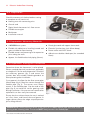
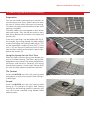
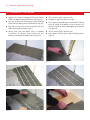
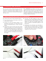
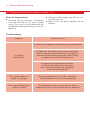
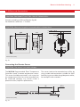
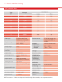
MYSON
ELECTRIC
UNDERFLOOR HEATING.
INSTALLATION MANUAL
APRIL 2013
Important: Please read carefully on receipt
of product and keep in a safe place.
heatingthroughinnovation.
Contents
1.0
General Information
03
2.0
Preparation
04
3.0
Measuring the Mat and Installation
05
4.0
Measuring Values/Resistance with the Multimeter
09
5.0
Connecting the Thermostat
10
6.0
Thermostat User and Installation Guide
10
7.0
Electrical Connection
13
8.0
Technical Data
14
Electric Underfloor Heating
03
1.0 General Information
The MYSON mat is manufactured from high
quality, durable materials. To guarantee that your
product functions optimally there are a few points
of attention which are described in the installation
manual. We can only offer you the full guarantee
if the mat is correctly installed in accordance with
the installation manual. Carefully read the
instructions prior to installation and ensure that
you have the correct tools and materials.
PLEASE NOTE: The electrical installation MUST BE carried out by a qualified electrician.
l
Before installing check if the heating mat is the
right size for the floor area to be heated and that
there is sufficient electrical capacity (Amps)
available. The mat should not be positioned over
expansion joints.
l
A distance from the wall of 100mm should
generally be adhered to. The mat may never be
installed under fixed objects like wall units,
kitchen units, baths or showers and must be able
to give off its warmth unimpeded.
l
If multiple mats are installed in an area then a
shared power point can be installed so that only
1 power cable runs to the thermostat. Maximum
capacity of the thermostat is 16 Amps. The
thermostat should be installed by a qualified
electrician. The power supply must be turned off
during installation.
l
The MYSON mat may only be incorporated into
the free floor/wall areas. As many bathrooms
consist mainly of a small free floor area the mat
may only be installed as supplementary heating.
Please contact your heating engineer who will
advise the heating requirement of the room.
l
l
The MYSON mat consists of a heating cable of
8-9 Watts per metre that is equally distributed
and connected to a glass fibre net with an
inter-loop distance of approximately 70mm.
The sensor MUST be installed in the middle of a
cable loop for optimal temperature registration.
Ensure that the sensor is installed well clear (min.
500mm) of hidden radiator and water pipes,
drains and electrical wiring.
l
Each mat is tested at the factory and has a unique
inspection card. Every mat is tested at 4000 volt.
You must check the mat after each installation
phase, in order to know at which phase any
defect occurs (section 4.0).
l
The sensor MUST always remain in the sensor
pipe. Cap the end of the pipe to avoid the sensor
getting stuck during installation. If the sensor
ever needs to be replaced it can then easily
be removed.
l
The heating cable, attached to the grey glass
fibre net, must NOT be broken. The mats must
NOT be laid over each other and the heating
cables must NEVER cross each other. The cable
junction (where the power supply cable joins the
heating cable) is just within the heating mat and
is marked.
l
A sufficiently strong and thick compression
resistant floor, with or without reinforcing, must
be applied on wood and insulation. If this is not
the case please contact Customer Services and
enquire about our other products.
l
The electric heating mat is guaranteed for 10
years. The thermostat is guaranteed for 2 years.
The guarantee does not apply to damage caused
by external factors and/or incorrect installation.
l
In compliance with the EU Directive
2006/66/EC, the button cell battery located on
the printed circuit board inside this product,
can be removed at the end of the product life,
by professional personnel only.
l
l
The mat has 1 connecting cable, which is 5
metres in length. The connector cable MUST
NOT be shortened by more than 3 metres, there
must therefore always be at least 2 metres of
connecting wire left. The power supply must be
turned off during installation.
The heating mat is 3 - 4 mm thick and must be
incorporated in an adhesive or screed suitable for
floor heating. Check the manufacturer’s data.
2
2
2
MAT
THERMOSTAT
04
Electric Underfloor Heating
2.0 Preparation
Check the contents of the box before starting.
A complete set will consist of:
l
Heating mat with connecting wire
l
Control card
l
Digital clock thermostat incl. floor sensor
l
Flexible sensor pipe
l
Multimeter
l
Installation manual
2.1 Preparation: Necessary Materials
l
A MYSON mat system.
l
Plastic glue comb with approx. 6mm teeth.
Flexible tile adhesive or levelling/screed and
grout suitable for floor heating.
l
Electrical junction box (min 40mm deep).
l
Power outlet with RCD 30mA.
l
Flexible cement and cement gun for expansion
joints along the walls.
l
Adhesive or double sided tape (for screeded
floors).
l
Approx. 2m flexible electrical piping (16mm).
l
2.2 Preparation: Placing the Thermostat
Determine where the thermostat is to be placed.
Place a standard electrical junction box*, preferably
at a height of 1.5m for ease of operation. Grind/cut
the necessary grooves (fig 1) and mount the
junction box and suitable sheathing/conduit to
allow plastering after installation.
Cut a groove in the floor for the floor sensor pipe
20mm deep (fig 2). Feed the sensor through the
flexible pipe (fig 3). The sensor must always
remain in the flexible pipe. Cap the end of the
pipe (fig 4) to avoid the sensor getting stuck
during installation. If the sensor ever needs to be
replaced it can then easily be removed.
Ensure that the surface where the mat is worked
on is flat, clean, and free of dust and grease. In
larger spaces place the edge strips/expansion
joints along the wall.
Fig. 1
Fig. 2
Fig. 3
Fig. 4
PLEASE NOTE: Never place the sensor in the vicinity of a hidden radiator pipe and never install it
passing under a heating cable. The sensor MUST always remain in the flexible pipe.
* See Section 7.0 Electrical Connection.
Electric Underfloor Heating
3.0 Measuring the Mat and Installation
Preparation
Test the mat before commencing installation to
ensure there are no faults. Allow a distance from
the wall of 100mm when rolling out the matting.
This does not apply to conservatories where extra
heating is required.
The loose cables must be looped at least 40mm
from each other. They should not touch or cross
each other. Retest the mat when it has been laid
(section 4.0).
Fig. 5
If the mat is too long it can be folded 180o (fig 5),
for example, by cutting through the fibre netting
without damaging the heating cable (fig 6). This
can be repeated a number of times (fig 7). If the
mat is still too long the cable can be cut loose
from the fibre netting and installed in loose strips,
please see section 3.3.
Using the System for the First Time
Fig. 6
Allow the floor sufficient drying time before you
turn on the floor heating. The floor’s drying time
depends on many factors like room temperature,
ventilation and moisture. Generally the drying
time for floor cement is 3 to 4 weeks. Please verify
this with the floor cement/screed manufacturer.
Tile Cement
Unroll the MYSON mat with the heating cable
facing down so that only the glass fibre netting is
visible (fig 8).
Fig. 7
Screed
Unroll the MYSON mat with the heating cable
facing up. This prevents the glass fibre netting
‘floating’ on the levelling screed. If necessary, the
mat can also be attached using double sided
adhesive tape.
Fig. 8
05
06
Electric Underfloor Heating
3.1 Installation: Tile Cement
l
Apply a first layer of cement of 5mm to 10mm
thick and approximately 550mm wide (fig 9).
l
Test the mat again (section 4.0).
l
Smooth it over and allow it to dry.
l
Pull the end of the connecting cable through
the electrical piping to the thermostat (fig 10).
l
l
Roll the mat out over the tile cement with the
cable facing downwards (fig 11).
Then apply a second layer of tile cement taking
care to avoid air bubbles using a plastic tile
cement comb to avoid damaging the heating
mat (fig 13).
l
Softly push the mat down with a wooden
instrument or gloves and spread the tile
cement that oozes through the mat (fig 12).
l
Test the mat again (section 4.0).
l
Press down the tile with a light sliding motion
(fig 14).
Fig. 9
Fig. 10
Fig. 11
Fig. 12
Fig. 13
Fig. 14
Electric Underfloor Heating
07
3.2 Installation: Screed
Position the mat as described in section 3.0.
Attach the mat to the floor with adhesive or
double sided tape (fig 15 -17).
Read the instructions of the levelling screed, check
that the product is suitable for floor heating and
follow the laying instructions of the manufacturer.
Test the mat again with a multimeter (section 4.0)
and write down the readings on the control card.
Observe the manufacturer’s drying time and then
apply the floor covering (fig 18).
AT THIS STAGE YOU SHOULD HAVE TESTED
YOUR MAT 3 TIMES.
PLEASE NOTE: Applying 2 separate levelling layers, one on top of the other, is NOT
RECOMMENDED because it can cause unnecessary tension in the floor.
Fig. 15
Fig. 16
Fig. 17
Fig. 18
08
Electric Underfloor Heating
3.3 Installation: Laying Variations
The mat can be laid in several ways, as illustrated in diagram below:
Never cut the heating cable.
PLEASE NOTE: Heating will only occur
where the mat has been installed.
Never cross the heating cables.
Visit our website to
use our Floor Plan
Calculator.
3.4 Installation: Laying Example
Please note that where there is no matting installed
the floor will not be heated.
If the mat is too long the cable can be cut loose
from the fibre netting and installed in loose strips.
The loose cables must be looped at least 40mm
from each other. They must not touch or cross each
other. See section 3.3 above.
The sensor must be installed in the middle of a
cable loop for optimal temperature registration.
Ensure that the sensor is installed well clear (min.
500mm) of hidden radiator and water pipes, drains
and electrical wiring.
The mat must never be installed under fixed
objects like wall units, kitchen units, baths, or
showers and must be able to give off its warmth
without being obstructed.
Electric Underfloor Heating
09
3.5 Installation: Other Possibilities
You can also use any section that you have left
over within the wall or a step to the bath. You can
include it in the plaster layer or apply it with tile
cement. This maximises the effective heating area
from your mat.
TIP: A MYSON Towel Warmer will give you the
comfort and convenience of warm dry towels, to
add to the luxury of your warm floor. This may
also give the benefit of additional heat. Please
contact Customer Services on 0845 402 3434 for
a Design Collection brochure.
4.0 Measuring Values/Resistance with the Multimeter
l
Connect the wires to the multimeter (fig 19).
l
Turn the knob of the multimeter to the Ohm
2000 position (fig 20).
l
Connect the red and black probe to the
connection wires (fig 21). The connection wires
(Phase and Neutral) have a clear insulation
sheath.
l
Do not touch the wires when measuring. Check
readings according to the control card which
was attached to the heating mat. If readings are
not within a 5% margin please check again
to make sure. Please call 0845 402 3434 and
cease installation if readings are not within a
5% margin.
l
Connect the RED probe to one of the
connection wires and the BLACK probe to the
Earth wire (fig 22). Earth wire has no sheath.
Repeat this step with the RED probe to the
other connection and BLACK probe to the
Earth wire.
l
Reading on the multimeter now should be ‘1’.
If you read any resistance there is a possible
break in the wires. Please check again. Please
call 0845 402 3434 and cease installation if
reading still shows resistance.
Fig. 19
Fig. 20
Fig. 21
Fig. 22
10
Electric Underfloor Heating
5.0 Connecting the Thermostat
Mounting:
l
Remove the frame
The controller should be mounted in a location of
the room that is easily accessible for operation
purposes.
l
Mount it following the reverse procedure
Fitting
In a conduit box Ø 60 mm (fig 23).
l
The plastic tab must be in place to provide
insulation between the terminals/wires and the
mounting screw (fig 24).
l
To insert or remove a flexible wire press pin
(fig 25)
Remove the display unit
CAUTION: Mounting in plastic wall boxes only.
Fig. 23
Fig. 24
Fig. 25
6.0 Thermostat User and Installation Guide
For full operating instructions, please refer to the instructions supplied with the product.
Principle of Operation:
The MYSON Programmable Floor Temperature
Controller allows programming switching events
and temperatures according to personal needs.
After installation the device automatically shows
the time of day and the floor temperature.
In AUTO mode, the heater will be automatically
activated according to programmed time and
temperature. Programme 1 is activated (see page
11). The floor temperature will be controlled
according to the temperature measured by the
remote sensor. The heater will be switched on
when the temperature drops below the current
set-point.
Installation:
CAUTION!
This device must be installed by a qualified
electrician, according to the wiring diagram on
the device and in compliance with all applicable
safety regulations. To maintain compliance with
Protection Class II, user access to the rear of the
device must be prevented. This device is used
to control the temperature only in dry rooms,
under normal environmental conditions. This
electronic device conforms to EN 60730, it is an
“independently mounted control” and works
according to operating principle 1C.
Electric Underfloor Heating
11
6.0 Thermostat User and Installation Guide (cont...)
Features:
l
Timer (Party) specific
configurable duration
l
Energy consumption display (heating on time *
cost) for last 2 days, week, month, year
temperature
for
l
One line text display for simplified operation
l
Back light
l
Real time clock (setting of year, month, day
and time)
l
Energy cost per hour configurable
l
Automatic Summer - Winter time change over
l
Frost protection
l
Max 9 events per day (each day independently)
l
l
Pre-set and adjustable programmes
Range limits for adjusting max and min
temperature
l
Optimum Start
l
Access protection
l
Operating language can be selected
l
Control mode PWM or ON/OFF
l
Arm chair programming (with display unit
removed)
l
OFF Function, Key V to be pressed for 10
seconds
l
Minimum output ON/OFF time and hysteresis
configurable for ON/OFF control
l
Holiday Mode (date from until can be set)
l
Floor temperature can be read as a number
Pre-set Programmes:
PROGRAMME 2
There are 3 pre-set time/temperature programmes
in the controller. Pre-set programme 1 (as shown
below) is the default. Therefore, if pre-set
programme 1 is the best programme to suit the
application, there will be no need to change the
time/ temperature settings on the device.
To select another programme choose from the
other options below.
Monday to Friday
Events
1
4
5
6
Temp °C
28.0 18.0
28.0
18.0 28.0
15.0
Saturday and Sunday
Events
1
2
3
4
5
6
Time
8:00 10:00 12:00 14:00 19:00 22:00
Temp °C
28.0 18.0
28.0
18.0 28.0
15.0
Monday to Friday
Monday to Friday
1
3
6:00 8:00 12.00 14.00 19:00 22:00
PROGRAMME 3
PROGRAMME 1
Events
2
Time
2
3
4
Events
1
2
3
Time
6:00 8:00
19:00 22:00
Time
11:00 13:00
22:00
Temp °C
28.0 18.0
28.0
15.0
Temp °C
28.0 18.0
15.0
3
4
Saturday and Sunday
Saturday and Sunday
Events
1
2
Events
1
2
3
4
Time
8:00 10:00
19:00 22:00
Time
8:00 10:00
19:00 22:00
Temp °C
28.0 18.0
28.0
Temp °C
28.0 18.0
28.0
15.0
15.0
12
Electric Underfloor Heating
6.0 Thermostat User and Installation Guide (cont...)
Notes for Programming
l
Activated settings terminate automatically
3 minutes after the last key press, without
saving. They return to the mode which was
active before entering the settings, e.g. AUTO,
MAN, etc.
l
Entering a Code: change value with the + or key then press OK.
l
Refer to the user guide supplied with the
product.
Troubleshooting
Problem
Possible Causes
The clock and programme events may not be set correctly
It is getting
warm too late
The Optimum Start feature may not be switched on refer to Optimum Start within the user guide (H7)
Did the controller have enough time (several days)
to adapt to the room’s characteristics?
An automatic change between Summer and Winter time may not be activated refer to Summer/Winter time changeover
within the user guide (G5)
The controller does not
accept any changes
The access protection may not be switched on refer to Key Lock within the user guide (G6)
The range of temperature
setting is limited
The temperature limits may not be set - refer to
temperature limits min/max within the user guide (G7)
Electric Underfloor Heating
13
7.0 Electrical Connection
CAUTION: DISCONNECT ELECTRIC CIRCUIT FROM SUPPLY.
Connect according to Wiring Diagram (fig 26).
For flexible or solid wires 1 - 2.5mm2.
CAUTION: Maximum length of removed cable insulation 8mm.
50
N
L
42.5
230V~ 50Hz
17.5
80.5
Load
N N
L
Sensor
Dimensions (mm)
Fig. 26
Connecting the Remote Sensor
CAUTION: The sensor is at mains voltage.
The MYSON Programmable Floor Temperature
Controller needs a remote temperature sensor.
This sensor should be mounted in such a way that
the temperature which has to be controlled can
be measured correctly. Lay sensor inside a
protective tube (simplifies replacement).
The sensor lead can be extended up to 50m by
using a cable and connections suitable for 230V.
Avoid laying sensor cable alongside power cables,
for example inside a conduit.
20
Dimensions (mm)
Fig. 27
Ø 7.8
14
Electric Underfloor Heating
8.0 Technical Data
Type
m2
Wattage
1
1.5
2
2.5
3
3.5
4
4.5
5
6
7
8
9
10
150W
225W
300W
375W
450W
525W
600W
675W
750W
900W
1050W
1200W
1350W
1500W
Heat Outputs
Amps
Ohm
0.65
0.97
1.30
1.63
1.95
2.28
2.61
2.93
3.26
3.91
4.56
5.22
5.87
6.52
353
235
176
141
117
100
88
78
70
59
50
44
39
35
Order type
Programmable Floor
Temperature Controller
Remote sensor
F 193 720, length 4m,
can be extended up
to 50m
Supply voltage
230 V AC 50 HZ
(195 ... 253 V)
Ambient
temperature
without condensation
Temperature
setting range
10°C to 40°C; in 0.5°C
steps
Temperature
resolution
0.1°C steps
Rated impulse
voltage
Output relay
NO contact
Ball pressure test
115°C
Switching current
10mA... 16(4)A AC*;
230 V~
230V, 0,1A
Output signal
PWM (Pulse Width
modulation) or ON/OFF
Voltage and
Current for the
purposes of
interference
measurements
PWM cycle time
adjustable
Degree of
protection
IP 30
Hysteresis
adjustable (ON/OFF only)
10 Min
Protection class
of housing
II (see Caution)
Minimum
programmable time
Pollution degree
2
Power consumption
~ 1,2 W
Software class
A
Accuracy of clock
< 4 Min / year
~280 g
Power reserve
~ 10 Years
Weight
(with remote
sensor)
- Operating
0°C … 40°C
- Storage
-20°C … 70°C
4 kV
NB. For current > 14 A do not loop the N-wire through the controller, use a separate terminal.
Electric Underfloor Heating
8.0 Technical Data (cont...)
Resistance Values for Remote Sensor
Temperature °C
Resistance k
10
20
25
30
40
50
66.8
41.3
33.0
26.3
17.0
11.3
PLEASE NOTE: On all these errors, heating will be activated with 30% of time.
Error Indication:
In case of errors, "Err" is blinking. The following errors can be displayed:
CONFIGURATION
COMMUNICATION
EXTERIOR SENSOR
Display and powermodule
do not fit
Communication between
display and power unit fails
l
l
use only suitable parts
l
l
switch off and on
power supply
l
unplug and re-plug
display unit
switch off and on
power supply
Please call customer services on 0845 402 3434
or visit www.myson.co.uk for more information
or after sales advice.
Scan the QR code to use our Floor Plan Calculator.
1. Error of remote sensor
replace sensor
2. Over or under run
of valid display range
15
MYSON
MYSON Eastern Avenue, Team Valley, Gateshead, Tyne & Wear NE11 0PG, UK
T: 0845 402 3434, F: 0191 491 7568, [email protected], www.myson.co.uk
01.04.2013
heatingthroughinnovation.