1
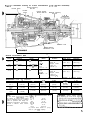
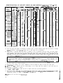
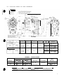
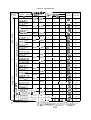
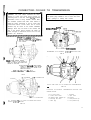
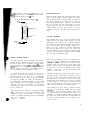
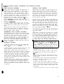
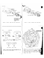
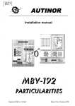
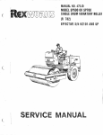
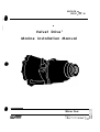
S E R V I C E It
PRICE ,_s3. 00
,
I
Velvet Drive”
Marine Installation Manual
Warner Gear
D~ws~orl
of Borg-Warner Corporation
P 0 . Box 2688. Muncie. IndIana 47302
Telephone 3171286-6100 Telex
27-491
2:
E$
TABLE OF CONTENTS
FQREWARD.................:‘.
................................
1
2
SERIES lo-17 AND lo-18 SERVICE INSTRUCTIONS. . . . . . . . . . . . . . . . . . . . . . .
3
SELECTINGAPRDPERVELVETDRIVE . . . . . . . . . . . . . . . . . . . . . . . . . . . . . . .
PROPELLERSELECTION.. . . . . . . . . . . . . . . . . . . . . . . . . . . . . . . . . . . . . . . .
4
INSTALLATION DRAWING FOR IN.LINE TRANSMISSIONS . . . . . . . . . . . . . . . .
5
CHART SHOWING IN-LINE MODELS AND MISCELLANEOUS DATA . . . . . . . . . . . 6
7
INSTALLATION DRAWING FOR V-DRIVE TRANSMISSIONS . . . . . . . . . . . . . . . .
CHART SHOWING V-DRIVE MODELS AND MISCELLANEOUS DATA . . . . . . . . . . 8
INSTALLATION DRAWING FOR DROP CENTER TRANSMISSIONS . . . . . . . . . . . . 9
CHART SHOWING DROP CENTER MODELS AND MISCELLANEOUS DATA. . . . . . 10
ADAPTER HOUSING . . . . . . . . . . . . . . . . . . . . . . . . . . . . . . . . . . . . . . . . . . . . .
11
TRANSMISSION INSTALLATION . . . . . . . . . . . . . . . . . . . . . . . . . . . . . . . . . . . .
11
TYPICAL INSTALLATIONS SHOWN PICTORIALLY . . . . . . . . . . . . . . . . . . . . . . 12
TRANSMISSION OPERATION . . . . . . . . . . . . . . . . . . . . . . . . . . . . . . . . . . . . . .
13
PROPELLERSHAFTCDUPLlNGS...................................14
COOLERS....................................................16
CONNECTING COOLER TO TRANSMISSION . . . . . . . . . . . . . . . . . . . . . . . . . . .
17
VIBRATION DAMPERS. . . . . . . . . . . . . . . . . . . . . . . . . . . . . . . . . . . . . . . . . . .
20
DAMPER APPLICATION CHART . . : . . . . . . . . . . . . . . . . . . . . . . . . . . . . . . . . . .
21
22
DAMPER INSTALLATION . . . . . . . . . . . . . . . . . . . . . . . . . . . . . . . . . . . . . . . . .
NEUTRALSAFETYSWITCH.......................................2
3
24
ROUTINE CHECKS AND MAINTENANCE . . . . . . . . . . . . . . . . . . . . . . . . . . . . . .
MATCHING ENGINE, TRANSMISSION AND PROPELLER ROTATION . . . . . . . . .25
,
I
FOREWORD
This manual covers all Velvet Drive@ transmissions. Data is given to assist you in selecting the proper transmission, cooler,
damper drive and propeller shaft coupling. Proper installation is a requirement for a valid warranty. Instructions for
making
a proper installation are included. Better service and extended product life can be expected when the recommended cornponents are used and properly installed.
THIS CHART HAS BEEN ADDED TO HELP IDENTIFY EARLY VELVET DRIVE ASSEMBLIES.
The following are identification markings for Warner Gear Division Marine Gears:
MODEL 70
I.D. NO.*
Y”o”Fk 71
. .
.
MODEL 72
1-D. NO.
FORWARD
RATIO
HAND OF
ROTATION
0
1
2
Direct
Both
04
14
24
‘I ,523 to 1
Both
05
05A
15
15A
25
25A
2.100 to 1
2.100 to 1
Counterclockwise
Clockwise
06
16
26
2.571 to 1
Both
07
17
27
2.909 to 1
Both
*These numbers are stamped on serial number plates preceding the serial numbers.
lo-17 & lo-18 UNITS
The 1: 1 ratio units in the 1 O-l 7 and 1 O-l 8 series are identical except for the nameplate to the 71 C and 72C units which
they repalce. The nameplate was changed to be consistent with reduction units of these models.
The forward and reversing portion of the reduction units of the IO-I 7 and IO-I 8 units is the same as the 71 C and 72C units
which they replaced. The reduction portion of the 1 O-1 7 and I O-l 8 units was changed to include a compression sleeve between
the two tapered bearing components. Tightening the coupling nut causes the sleeve to be compressed, allowing the tapered
bearing to be preloaded. A bearing retainer is not used and the rear oil seal is pressed into the reduction housing.
The reduction sun gear is pinned to the housing of 71 C and 72C 1.5: 1 units. The snap ring holds the sun gear to an adapter
plate which is bolted to the reduction housing of 1 O-l 7 and 1 O-l 8 reduction units. An oil baffle is bolted to the reduction
of 2.57: 1 and 2.91 : 1 reduction units of the 1 O-l 7 and 1 O-l 8 series transmissions.
- IMPORTANT SERIES IO-17 AND IO-18 SERVICE INSTRUCTIONS
Practically all information which has been written for the 71 C and 72C Velvet Drive transmissions applies to the IO-I 7 and
1 O-l 8 assemblies. Use the appropriate instructions given in the 71 C and 72C service manuals when servicing the 1 O-l 7 and
IO-18 transmissions. Use instructions given below for assembling the bearings and output shaft into the reduction housing.
Press two bearing cups into the reduction housing. Place rear bearing cone into the rear bearing cup. Press the oil seal into the
reduction housing until rear face of oil seal is flush with rear face of bore in housing. Press the front bearing cone over output
shaft and against face of shaft. Assemble the bearing sleeve over shaft and against cone. Lower the reduction housing over shaft
components. Grease lips of oil seal and install the coupling and nut to the output shaft.
Locate reduction housing and attached
shaft so that the reduction housing can
coupling while the output shaft nut is
should be tightened until an increase
parts on a suitaJ.$e block placed under
be rotated as the coupling nut is being
being tightened. A helper should rotate
in effort required to turn the reduction
the carrier or other parts attached to the output
tightened. A tool should be used to hold the
the reduction housing and the coupling nut
housing is noted.
Lay the reduction housing on its side and use a torque wrench to turn the output shaft through the bearings to check
bearing drag caused by the bearings being preloaded. A maximum of 45 lb-ins (5.1 Nm) but perferably 15 to 30 lb-ins
3.4 Nm) torque should be required to rotate the output shaft through the oil seal and properly preloaded bearings. A
bearing spacer should always be used after the output shaft nut has been loosened after being properly preloaded. If
must be reused, always go to a slightly higher preload than the sleeve had been torqued.to previously.
IMPORTANT - SEE LATE BULLETINS ON THESE MODELS.
2
the
(1.7 to
new
the spacer
SELECTING A PROPER VELVET DRIVE
Optimum performance can only be obtained when all com-
The pump must be correctly indexed for each direction of
ponents
Appli-
rotation. An arrow with TOP L.H. and a second arrow with
cations having components which are excellent for a par-
TOP R.H. can be found on early pump housings. The
ticular use may be completely unsuitable for another use.
arrow which is located nearer the top of pump housing
are
properly
selected
for
the
application.
Basic considerations for component selection are discussed
points in the direction the pump must rotate to pump oil.
in this manual. Specific information is given for the various
The letters L.H. and R.H. describe the required pump
Velvet
be
rotation when facing the pump and tells the same thing as
made to help you find information which is not included.
the arrow points out. The letters L.H. and R.H. have been
Drive
models.
Reference
to
various
forms
will
removed
ENGINE
from
current
pump
assemblies.
ROTATION
The wise mechanic will always check the pump setting
Transmission selection will be simplified when the following
prior to transmission installation to be sure that the arrow
method is used to describe engine rotation. This method
agrees with engine rotation.
may not agree with the engine manufacturers’ for describing engine rotation.
Pump rotation is viewed from the opposite end of the
transmission from which shaft and engine rotation is
Face the end of the engine on which the transmission is
described. The arrow showing left hand rotation should be
mounted and describe rotation as clockwise if the engine
nearer the top of the units used behind clockwise rotating
rotates clockwise. Describe the engine rotation as counter-
engines. The arrow showing right hand rotation should be
rotating
if
the
engine
rotates
nearer the top on units used behind counterclockwise
counterclockwise.
rotating
TRANSMISSION
engines.
ROTATION
TO INDEX PUMP FOR OPPOSITE HAND ROTATION
Describe
transmission
input
and
output
shaft
rotation
clockwise or counterrotating (counterclockwise)~hen
as
stand-
ing behind the transmission coupling facing towards the input or engine end ot the transmission.
All Velvet Drive units except the 2.1O:l
In-Line and
CR2 units may be used behind engines having either
rotation; however, the pump must be indexed for the
desired rotation. The reduction unit planetary carrier is’
CAUTION: This procedure is not applicable to
‘CR2 units or the AS3, AS1 3, 10-l 7 and 1 O-l 8
models (2.10:1 In-Line reduction ratios) because
special planetary gear mountings are used which
are different for each rotation. These models must
not be reindexed from the oriqinal factor-v settings.
1) Remove the four bolts which hold the pump to the
transmission,
(Fig.
1).
different for opposite rotating 2.lO:l In-Line units and
early failure will occur on these units if they are driven
2) Loosen the pump housing. A rubber or plastic hammer
in the wrong direction.
may be used to tap the oil boss, but do not strike the bolt
The output shaft rotates in the same direction or in the
opposite
direction
to
the
input
shaft
depending
upon
the
transmission assembly; therefore, it is best to study the
charts which show shaft rotation to determine the required
model.
bosses.
3) Do not remove the pump from the shaft unless a seal
protector is used to prevent the shaft splines from cutting
the pump seal.
4) Care should be taken to see that the pump gasket does
HYDRAULIC
PUMP
INDEXING
not stick to the pump housing during rotation, causing the
gasket to be folded or torn.
The transmission front adapter and pump housing are designed to permit the pump to be mounted in either of two
positions. Each position permits oil to be pumped when
pump gears are rotated in one direction only. The pump can
5) Locate pump with the arrow indicating the proper
only pump oil when any point on the gears is rotated past
the inlet port first, then past the crescent shaped portion
6) Care must be taken to see that the gasket, seal and bolt
of the pump housing which separates the inlet from the
these critical areas.
direction of input shaft rotation nearer top of transmission.
bosses are kept in good condition to prevent leaks in
outlet and then past the pump outlet.
7) Torque the four bolts to 17-22 ft. Ibs. (25.3-32.7 Kg/M.).
3
FIG. 1 VIEW FACING PUMP AND INPUT SHAFT
PROPELLER ROTATION
speed, which has a direct relationship to boat speed. A
small propeller must be used when shaft speeds are too high
A right-hand propeller is a propeller which will thrust for-
and this results in poor performance. A large propeller
ward when turned clockwise when viewed from behind the
turning at high speed would overload the engine. Fast
boat
runabouts do best with direct drive units. Cruisers require
looking
forward.
reduction gears. The heavier and slower boats require
A
left-hand
propeller
is
a
propeller
which
will
thrust
for-
ward when turned counterclockwise as viewed from behind
the
boat
looking
forward.
correspondingly
greater
ratios
of
reduction.
One
hundred
revolutions per minute of the propeller shaft for each mile
per hour of boat speed is considered a very good rule of
thumb for selecting the drive ratio.
CAUTION: Early gearfailure will
transmission
must
be
operated
in
forward when operated with a
the wrong hand of rotation.
reverse
to
propeller
obtain
having
EXAMPLE:
A boat which runs 20 MPH has an engine which runs
4000 RPM. MPH x 100 RPM propeller shaft=optimum
shaft speed, or 20 x 100=2000
The required propeller is designated in the various charts
as left hand (L.H.)
mission
or right hand (R.H.) for each trans-
assembly,
4000 = Engine Speed
2000 = Shaft Speed
TRANSMISSION
RATIO
RPM would be optimum
shaft speed.
or? Reduction
Required
1
SELECTION
Propeller shaft speed is determined by engine speed and
transmission ratio. Every boat has a most desirable shaft
PROPELLER SELECTION
The propeller is selected to load the engine and still per-
normally high loading within the engine. This can result in
mit full power to be developed. The propeller must allow
destructive
the engine to come up to rated speed. It is incorrect to use
mature bearing and valve failure.
pressures
and
temperatures
which
cause
pre-
a propeller so large that the engine will be overloaded, because this will not only reduce the power delivered to the
propeller shaft, but more importantly it will cause ab-
4
For ski towing, it is best to select a propeller which will
permit the engine to maintain rated RPM when under load.
Figure
2 Installation drawing for In-Line transmissions (2.1O:l.OO ratio illustrated)
Reverse Planetary
Gear Set
Reverse Clutch
Forward
Clutch
Forward, Neutral,
Reverse Selector
I
I
Reduction Planetary
Gear Set
/
.
Reduction Case
Forward Reverse
Transmission Case
Self-cktained
Oil Pump
General
Performance
Data
Maximum SAE HP Input (1)
Model
Gasoline
2 5 5 @ 4 2 0 0 rpm
Diesel
145 @ 3200 rpm
72C
IO-18
3 8 0 @ 4 2 0 0 rpm
1 8 5 @ 2800
or 2 1 0 @I 3200
73c
1 O-06
5 6 0 @ 4 2 0 0 rpm
4 0 0 @ 3 2 0 0 rpm
71c
10-17
Dimensions
Inches
and
_
Available
Ratios
1 .oo
1.52
1 ._!91*
2.10
2.57
2.91 t o 1 .oo
1 .oo
1.50
2.00*
3.00 t o 1 .oo
Shaft
Rotation
Approximate
Direct Drive
Dry
Weight
Reduction
Outside
same as
Engine unless
noted by
asterisk (*)
95 lb.
(43.1 kg.)
145 lb.
(65.8 kg.)
1.09 lb.
(49.4 kg.)
153 lb.
(69.4 kg.)
output
same as
Engine unless
noted by
asterisk (*)
135 lb.
(61.2 kg.)
185 lb.
(83.9 kg.)
*Rotation
(millimeters)
C(Z)
is
opposite
engine.
Model
71c
10-l 7
A
6
D dia.
E dia.
5.63
(143.00)
5.69
(144.53)
1 6 .8 9
(429.01) , ,
2.50
(63.50)
4.2513’
(107.95)
F dia.
5.00’3’
(127.00)
72C
10-I 8
5.63
(143.00)
5.69
(144.53)
17.79
(451.86)
2.50
(63.50)
4.25
(107.95)
5.00
(127.00)
73c
1 O-06
5.94
(150.88)
6.88
(1 74.75)
19.45
(494.03)
3.00
(76.20)
4.75
(120.65)
(2) For”C” dimension-direct drive
Notes:
(1) The above transmission
ratings units:
71c
are subject to change without notice
10.50
10-l 7
and are Intended only as a general
(266.70)
guide for pleasure craft usage. For
72C
11.44
additional application information,
lo-18
(290.58)
consult a Warner Gear marine
73c
13.47
distributor.
1 O-06
(342.14)
(3) Direct drive model 71 (only)
uses 4” (101 .60) coupling.
5.75
(146.05)
WARNING: System related noises
or vibrations can occur at low engine
engine as well as the transmlsslon.
total system related torsionals of
IDENTIFICATION OF VELVET DRIVE IN-LINE MODELS 7OC, 71C, 72C & 73C
--
NEW
TRANS.
ASSEMBLY
NUMBER
TRANS.
ASSEMBLY
NUMBER
1 O-04-000-022 '
10-04-000-023 '
1 O-04-000-026 '
1 O-04-000-027 '
10-04-000-028 '
lo-04.000.029*
1 o-04.000.030.
10-04-000-031 '
1 O-04-000-032 '
10-04-000-033 '
10-04-000-034 '
10-04-000-035 '
1 O-04-000-024 '
10-04-000-025
'
_____
1 O-l 7-000-001 '
1 O-1 7-000-002 '
1 o-1 7-000-003
1 o-1 7-000-004
1 o-1 7-000-005
IO- 17-000-006
1 o- 1 7-000-009
1 o-1 7-000-010
1 O-l 7-000-01 1
1 o-1 7-000-012
10-17-000-013
10-l 7-000-014
1 O-l 7-000-007
1 O-1 7-000-008
1 o-1 7-000-015 '
10-17-000-016 '
1 O-l E-000-001
lo- 1 E-000-002
1 o- 18-000-003
1 O-l 8-000-004
1 o-1 8-000-007
1 O-1 8-000-008
1 O-1 E-000-009
10-18-000-010
10-l 8-000-01 1
10-l 8-000-012
1 o- 18-000-005
1 o- 18-000-006
1 O-1 E-000-01 3
1 O-1 E-000-01 4
10-06-000-004
1 O-06-000-005
10-06-000-006
1 O-06-000-007
10-06-000-008
1 O-06-000-009
10-06-000-010
1 O-06-000-01 1
(8)
___-
AS1 -70C
ASb70CR
AS2-70C
AS2-70CR
AS3-70C
AS370CR
AS14-70C
AS14-70CR
AS1 5-70C
AS1 5-70CR
AS7-70C (5)
AS7-70CR j5
ASlO-70C (7
ASlO-70CR (;
-1F
ASl -71C
AS1 -71 CR
ASl -71CB (6)
AS1 -71 CBR (I
AS2-71C
ASZ-71 CR
AS3-71 C
AS3-71 CR
AS14-71C
AS14-71CR
AS1 5-71 C
AS1 5-71 CR
AS7-71C
AS7-71CR
ASZO-71C (7)
AS20-71 CR (7
AS1 l-72C---I
AS1 l-72CR
AS12-72C
AS1 2.72CR
AS1 3-72C
AS1 3.72CR
AS14-72C
AS14-72CR
AS1 5.72C
AS1 5.72CR
AS1 7.72C 15
AS17-72CR ' (
AS20-72C (7
AS20-72CR (
AS20-72CR (
AS30-72CR (
AS1 -73C
ASl -73CR
AS2-73C
AS2-73CR
AS5-73C
AS5.73CR
AS7-73C (51
AS7-73Cd (5
*Discontinued
INPUT TO OUTPUT
SPEED RATIO
ORWARD
11
ROTATION
c
I NPUl
R EVERSE L‘jHAF1
1 ( w
F
1 :l
1 52: l
1 52.1
2 10.1
2 10.1
2.57: l
2 57 1
2 91.1
291 1
1 91 1
191.1
1 1
1 1
-
r
1 1
1.52:1
1.52:1
2.1O: l
2.10.1
2.57:1
257 1
291 1
291.1
1 91 1
1 91.1
1 1
1 1
cZCW
(:w
(: c w
(3W
, 3CW
I :w
I 3cw
, 3W
, 3CW
,3W
t3cw
I ZW
,zcw
1.1
1.1
1 1
1 1
1.52.1
1 52 1
2 . 10 1
2101
2 . 57 1
2 57.1
291 1
291 1
1 91 1
1 91.1
1 1
1 1
1 1
1.1
1.1
1.1
1 52.1
1.521
2. lO: l
2101
257 1
2 . 57 1
2 91.1
.x91:1
1 91 1
191.1
1 1
1.1
C W
,ccw
/C W
,ccw
,cw
ccw
c w
ccw
c w
ccw
c w
ccw
c w
ccw
c w
c c w
1 1
1.1
1 .52,1
1 . 52 1
2 10.1
2 . 10 1
2 . 57 1
2 . 57 1
291 1
291 1
1 91.1
1 . 91 1
1.1
1 1
1 1
1 1
1.10.1
1 10.1
1.68:1
1 68.1
231 1
231 1
2 83 1
2 83.1
3.20.1
3 20.1
2101
2101
1 10.1
1 1O: l
1 10.1
1.10.1
c w
c c w
c w
ccw
C W
c c w
c w
ccw
c w
c c w
c w
c c w
c w
c c w
c w
c c w
1.1
1 1
1 5.1
151
88: l
88:1
1 32 1
1 32.1
2 . 64 1
2.64:1
1 . 76 1
1 76: l
c w
ccw
c w
ccw
8
2.1
21
KW
c w
c c w
(1)
OUTPU
iHAFT
ORWARC
IEVERSE
cw
ccw
cw
ccw
cw
ccw
cw
ccw
cw- *
ccw
ccw
cw
cw
ccw
cw
ccw
cw
ccw
cw
ccw
cw
ccw
cw
ccw
cw
ccw
ccw
cw
cw
ccw
-__
cw
ccw
cw
ccw
cw
ccw
cw
ccw
cw
ccw
ccw
cw3 I
UMP
TTINI
(2)
: cw
ZW
3cw
:W
3CW
3W
3cw
3W
zcw
,W
,W
ECW
ICW
CW
__ .
Tr
RH
LH
RH
LH
RH
LH
RH
LH
RH
LH
RH
LH
R H.
-
ROPELLER
EDUIREO
(3)
RH
LH
RH
LH
RH
LH
RH
LW
RH
LH
LH
RH
F
OIL CAP,
L
15"
13
27
27
2.7
27
27
2.7
27
2.7
27
27
1.7
1.7
-_ .
13
13
1.3
13
27
27
27
27
27
27
2.7
27
2.7
27
1.7
17
RH
EW
c w
c w
c c w
c c w
c w
LH
RH
LH
RH
LH
RH
LH
RH
LH
RH
LH
RH
LH
RH
LH
RH
LH
RH
LH
RH
Lti
RH
LH
RH
LH
RH
LH
RH
LH
RH
LH
RH
RH
LH
RH
LH
RH
LH
RH
LH
RH
LH
LH
RH
KW
c w
c c w
c
c
c
c
c
c
c
c
c
c
c
c
c
c
c
c
1.7
17
28
2.8
2.8
2.8
28
28
28
29
2.9
28
1.7
17
17
1.7
c w
c c w
c w
c c w
c w
ccw
c c w
c w
c c w
c w
c c w
c w
c c w
c w
c w
ccw
cn
AH
LH
RH
RH
LH
RH
LH
RH
LH
LH
RH
15
15
22
2.2
22
22
22
22
ccw
c w
ccw
c w
xw
c w
ccw
c w
ccw
c w
w
c w
w
c w
w
c w
w
c w
w
w
c w
c w
w
c w
w
I
K
LH
RH
k"H
LH
RH
LH
RH
LH
RH
LH
RH
LH
LH
RH
1
I
U.S.
QTS.
-Tr
i-
TTr
U.S.
DTS.
r
1 23
1 23
1.23
1 23
2.56
2.56
2 56
2 56
2.56
2.56
2.56
2.56
2.56
2 56
1.61
161
~--~
ITERS
1 23
2.56
2.56
2.56
2 56
2 56
2 56
2 56
2 56
2 56
2 56
1.61
1 61
~--~
rPPROX. TRANS.
W EIGIHT
LE
INCLINE0
1.61
1 61
2.65
2 65
2 65
2 65
2.65
2.65
2.65
2.65
2.65
2 65
1 61
1.61
1.61
161
1 .42
1 42
2.08
2 08
2.08
2 08
2 08
2 08
ITERS
P OUND
T7u-
T
1.8
18
1.8
1.8
2.5
25
25
2.5
25
2.5
2 5
25
2.5
25
2.1
21
1 70
1 70
1.70
1.70
2.37
2 37
2 37
2 37
2.37
2.37
2 37
2 37
2 37
2.37
1 99
1 99
95
95
95
95
145
145
145
145
145
145
145
145
145
145
98
98
21
21
2.7
2 7
2 7
27
27
2.7
27
2.7
27
27
2.1
21
21
21
16
1.99
1.99
2.56
2.56
2 56
2.56
2.56
2.56
2 56
2.56
2.56
2 56
1.99
1.99
1.99
1 99
151
1 51
1 89
1 89
1.89
1 89
1 89
1 89
109
109
154
154
154
154
154
154
154
154
154
154
112
112
116
116
43 . 1
43 1
43 1
43 1
65 8
65 8
65.8
65 8
65 8
65 8
65.8
65.8
65 8
65 8
44.5
44.5 49.4
49.4
69 9
69.9
69.9
69 9
69 9
69 3
69 9
69.9
69.9
69 9
50.8
50 8
52.6
52.6
135
135
185
185
185
185
185
185
61.2
61.2
63.9
83 9
83.9
83 9
83.9
83 9
18
2.5
2 5
2.5
25
2 5
2.5
2 5
25
25
2.5
2.1
21
:.:
20
20
20
20
20
1 70
2.37
2 37
2 37
2.37
2.37
2 37
2 37
2.37
2 37
2 37
1 99
1.99
92
142
142
142
142
142
142
142
142
142
142
95
95
i
KGS.
TTT-
t
41.7
64.4
64.4
64.4
64.4
64 4
64 4
84 4
64 4
64.4
64.4
43 . 1
43
.~. . 1
Models
(1)
Input and output shaft rotation is described as clockwise (CW) or counter clockwise (CCW) when the observer is standing
behind transmission coupling facrng towards front or input shaft end of transmission.
(2)
Pump rotation IS described when the observer is standing in front of transmission facing the pump. The arrow located
nearest the top of pump face must point in the direction pump will be driven by the input shaft. IT SHOULD BE REALIZED
THAT INDEXING THE PUMP FOR OPPOSITE ROTATION DOES NOT CAUSE OUTPUT SHAFT ROTATION TO BE
REVERSED, but does permit the transmission to be used behind an opposite rotating engine. All 1 O-06 units may have
pump indexed for oppostte
rotation.
CAUTION: The pump Indexing on all assemblies except 2.lO:l
reduction units is the only difference between C and
CR units, The planetary gears and cage assemb!y used in C units is different than the one used in CR units in the
2.10:1 reduction units; therefore, indexing the pump for opposite rotation is not permttted on these assemblies. No
warranty claims WIII be allowed for failures caused by improper pump indexing on 2.10:1 reduction units.
,
( 3 ) The propeller is described when the observer is standing behind the boat looking forward. A right hand( RH) prop will move
the boat forward when rotated clockwise.
(4) Transmrssion
(5)
AIf AS7 and AS1 7 reduction units are counter-rotating, i.e. the output shaft turns opposite to input shaft when the
transmission is operated in forward.
(6) The AS1
(7)
oil capacity only is given. Additional oil will be required for filling oil cooler and cooler lines.
-71 CB and AS1 -71 CBR units are for heavier reverse duty and diesel applications.
Warner Gear supplies AS1 0-7OC, AS1 O-70CR, AS20-71 C, AS20-71 CR, AS20-72C, AS20-72CR. AS30-70C and AS3072C units for use with stern drives. V-Droves or other auxilary reduction gears. Contact the manufacturer of the
supplementary gearing for details of the complete assembly.
(8) Al) Model 70C units have been drscontinued.
6
FIG.
3
INSTALLATION
DRAWING
FOR
V-DRIVE
TRANSMISSIONS
NOTE: Parenthatical
B
C
D
2.38
19.15
11.65
(60.45)
(486.41)
(295.91)
E
1
F
71C SERIES
I
72C SERIES
10.19
(194.06)
12.59
(67.06)
(509.52)
(319.79)
MAXIMUM SAE HP INPUT
MODEL
GASOLINE
1 O-04
255 @ 4200 rpm
145 @ 3200 rpm
10-05
3 8 0 @ 4200 rpm
12 81 50 @
@ 23 82 00 00 rr pp m
m
NOTE: All speclficatlons
DIESEL
and descriptive
8.58
(217.93)
1
REDUCTION
.96,1,
2.49:1,3.14:1
10.14
1257.56)
1.51:1,
.96:1.
1
1.21:1,
(258.83)
10.19
20.06
GENERAL
L
7.64
I
2.64
L
dimensions are in millimeters
1.99:1
1.21:1
(258.83)
2.49:1,3.14:1
10.14
(257.56)
1.51:l. 1.99:1
SPECIFICATIONS
AVAILABLE
OUTPUT
DRY
RATIOS
ROTATION
WEIGHT
0.96, 1.21, 1.51,
1.99, 2.49,
3.14 to 1.00
OPTIONAL
data are nomlnal and subject to change wtthout
1 9 0 lb. (86.2 kg.)
2 0 3 lb. (92.1 kg.)
notIce.
*
Spaclflc
lnstallatlons should be referred to Warner Gear for appllcatlon assistance.
7
V-DRIVE ASSEMBLIES
I
I
M O D E L
NUMBER
._.-.
1 IIUPU
1
ASSEMBLY
& TYPE
.-
--
I I
SI -lAFT
NUMBER
FORWARD
*
1 O-04-000-002
1.99:1
-.
I
.--.
.-
u uurw7
RATIO
ROTATION
l7EF-i
. . . . -.
SHAFT
REVERSE
1.99:1
(13-08-41 O-002)
10-04-000-005
(13-08-41
2.49: 1
2.49: 1
O-005)
REQUIRED
-
LH
C
c c
C
c c
c c
C
C
C
LH
c c
c c
C
-
c c
-
RH
RH
C
c c
C
c c
c c
C
-
LH
RH
10-04-000-009
0.96: 1
0.96: 1
C
c c
C
c c
c c
C
-
LH
RH
1 o-04.coo-o 11
(13-08-41 o-01 1)
1.51:1
1.51:1
C
c c
C
c c
c c
C
-
LH
RH
10-04-000-0 12
(13-08-41 O-01 2)
1.21:1
1.21:l
C
c c
C
c c
c c
C
-
LH
10-04-000-003
I .98: 1
C
c c
C
-
RH
c c
C
c c
-
LH
C
c c
c c
C
C
c c
-
RH
LH
C
c c
C
C
-
RH
c c
-
LH
c c
C
C
c c
-
RH
LH
C
c c
C
C
c c
-
RH
c c
RH
(13-08-41
2.50: 1
1.98:1
3.1O:l
3.10:1
O-006)
cc
1 O-04-000-008
1’13-08-41
2.60: 1
O-004)
1 O-04-000-006
(13-08-41
0.97: 1
0.97: 1
C
o-00$)
10-04-000-010
1.53: 1
1.53:I
( 13-08-41 O-01 0.)
10-04-000-0
13
1.21:1
1.21:I
1.99: I
2.19:1
10-05-000-005
2.49: 1
10-05-000-007
3.14:I
2.74: I
3.45: 1
O-007)
10-05-000-009
(13-08-41
0.96: 1
1.06:1
O-009)
10-05-000-011
1.51:1
1.67:1
(I 3-08-41 O-01 1)
10-05-000-012
1.21:l
1.33: 1
(13-08-41 O-01 2)
10-05-000.003
1.98: 1
2.17:1
(I 3-08-410-003)
10-05-000-004
- (13-08-41
2.50: 1
1 O-05-000-006
3.10:1
~13-08-410-008)
3 . 4 1 :l
I
.97: 1
1
2.75: 1
O-004)
3-08-41 O-006)
c c
C
c c
c c
C
-
LH
C
c c
C
c c
C
-
LH
c c
C
c c
C
c c
c c
C
-
LH
RH
C
C
c c
cc
C
-
LH
c c
C
c c
C
c c
c c
C
-
LH
C
c c
C
c c
c c
C
-
LH
C
c c
c c
C
C
c c
C
-
c c
C
c c
-
RH
LH
C
c c
c c
C
C
c c
-
RH
LH
C
c c
C
-
RH
c c
C
c c
-
LH
C
c c
C
c c
-
RH
LH
c c
(I 3-08-41 O-005)
(13-08-41
C
C
~13-08410-002)
1.07:1
1
1
I
-- CLOCKWISE
:C-- C O U N T E R C1 L O C K W I S E
*
I
LH
c c
C
c c
1 O-05-000-002
c c
RH
-
C
II 3-08-41 O-01 3)
z
REVERSE
PROPELLER
3.14:1
10-04-000-004
1
F O R W A ,RD
PUMP
SETTING
3.14:1
(13-08-41 O-003)
w
,
SHAFT
10-04-000-007
(I 3-08-41 O-007)
(I 3-08-41 O-009)
2
z
3
““I
n”TPUT
YU
I
I
cc
c
1
C
cc
C
cc
I
LH
RH
RH
RH
RH
RH
RH
-
1
-
I
-
I
LH
RH
LH
The(13-08.410)number
below the number for the V-DI-lve assembly IS the part
n u m b e r fat- t h e V-Drive portlon o n l y . 1 0 - 0 4 - 4 1 0 - 0 0 1 i s t h e p a r t n u m b e r f o r t h e
Front Bdx
only (forward ahd reverse transmiwonj
10-05-410-001 is for the IO-05 units.
for the lo-04
units
and
.
4
INSTALLATION
DRAWING
FOR
DROP-CENTER
TRANSMISSIONS
NOTE: ParenthetIcal dimensions
J-lMODEL
A
C
E
F DIA
a r e in mllllmeters.
G DIA
71C SERIES
1.23
1.06
(31.241
(26.921
1.66
1.49
(42.16)
137.85)
1.95
1.77
(49.53)
(44.96)
1.58
2.03
6.82
18.42
.31
4.25
.45
1173.23)
t 467.87)
17.87)
1107.95)
(11.43)
,
4
2.47
1 .99
2.93
,
72C SERI
1.58
(50.55)
1
1.23
1.06
(31.24)
(26.92)
>
2.64
19.36
.31
(67.06)
(491.74)
(7.87)
7.76
(197.10)
4.25
(107.95)
5.00
(127.00)
2.16
1.99
(54.861
(50.55)
2.93
L
GENERAL SPECIFICATIONS
MAXIMUM SAE HP INPUT
AVAILABLE
MODEL
GASOLINE
DIESEL
RATIOS
10-13
2 5 5 @ 4200 rpm
130 @ 3200 rpm
1.58, 2.03, 2.47.
IO-14
3 8 0 @ 4 2 0 0 rpm
m
21 18 50 @
@ 23 82 00 00 rr pp m
2.93 to 1.00
OUTPUT
DRY
ROTATION
OPTIONAL
WEIGHT
’
1 6 2 lb. (73.5 kg.)
1 7 5 lb. (79.4 kg.)
NOTE: The above transmission ratings are subject to change without notice and are Intended only as a
general guide.
Speclflc applications should be t-eferred
to Warner Gear for engineer-fng
awstance
9
NE=NON-AUTOMOTIVE ENGINE
E=AUTOMOTIVE ENGINE
O=AUTOMOTIVE
OPPOSITE
CR2
(DROP CENTER ASSEMBLIES)
A S S E M B L Y
NUMBER
REDUCTION
FORWARD
RATIO
S H A F T R O T A T I O N (1)
.
REVERSE
OUTPUT
INPUT
%
PUMP ‘2’
SETTING
(3)
PROPELLER
REQUIRED
NAME
PLATE
STAMPED
FORWARD
REVERSE
ENGINE
OPPOSITE
ENGINE
+
L.H.
E - l .6
-
R.H.
O - l .6
-
L.H.
E-2.0
1 O-l 3-000-001
1.58:1.
1.58:1
(41
L.H.
1 O-l 3-000-002
1.58:1
1.58:1
L.H.
OPPOSITE
__.-._._
ENGlNE
1 O-l 3-000-003
2.03: 1
2.03: 1
L.H.
E,[)IGINE
OPPOSITE
ENGINE
1 o- 13-000-004
2.03: 1
2.03: 1
L.H.
OPPOSITE
ENGINE
ENG,NE
-
R.H.
O-2.0
1 O-l 3-000-005
2.4J:l
2.4J:l
L.H.
ENGINE
OPPOSITE
ENGINE
-
L.H.
E-2.5
IO- 13-000-006
2.47: 1
2.47:1
L.H.
ENGINE
-
R:H.
O-2.5
10-I
2.93: 1
2.93: I
I-H.
OPPOSITE
ENGINE
ENGINE
OPPOSITE
ENGINE
-
L.H.
E-3.0
1 O-l 3-000-008
2.93: 1
2.93:1
L.H.
-
R.H.
O-3.0
I o- 13-000-009
1.58:1
1.58:1
R.H.
OPPOSITE
ENGINE
ENGINE
+
R.H.
NE-l.6
IO-I
3-000-010
2.03: 1
2.03: 1
R.H.
ENGINE
+--
R.H.
NE-2.0
1 O-l 3-000-01 1
2.47: 1
2.47~1
R.H.
ENGINE
-
R.H.
NE-2.5
1 O-l 3-000-012
2.93:1
2.93: 1
R.H.
ENGINE
OPPOSITE
ENGINE
-
R.H.
NE-3.0
3-000-007
ENGlNE
OPPOSITE
ENGINE
OPPOSITE
ENGINE
OPPOSITE
ENGINE
I
1 O-I 4-000-001
1.58:1
1.74:1
L.H.
ENGINE
OPPOSITE
ENGINE
-
L.H.
E - l .6
IO- 14-000-002
1.58: 1
1.74:1
L.H.
OPPOSITE
ENGINE
ENGlNE
-
R.H.
O - l .6
20-14-000-003
2.03: 1
2.23: 1
L.H.
ENGINE
OPPOSITE
ENGINE
-
L.H.
E-2.0
1 O-l 4-000-004
2.03: 1
2.23: 1
L.H.
ENGINE
-
R.H.
E-2.0
1 O-l 4-000-005
2.47: 1
2.7211
L.H.
OPPOSITE
ENGINE
ENGINE
OPPOSITE
‘ENGINE
-
L.H.
E-2.5
1 O-l 4-000-006
2.47: 1
2.72: 1
L.H.
OPPOSITE
ENGINE
-
R.H.
O-2.5
OPPOSITE
ENGINE
-
L.H.
E-3.0
ENGINE
1 o- 14-000-007
2.93: 1
3.22: 1
L.H.
ENGINE
1 O-1 4-000-008
2.93: 1
3.22: 1
L.H.
OPPOSITE
ENGINE
ENGINE
-
R.H.
O-3.0
1 O-l 4-000-009
1.58:1
1.74:1
R.H.
ENGINE
OPPOSITE
ENGINE
c-
R.H.
NE-l.6
(1)
VIEWED
FROM
BEHIND
COUPLING
FACING
ENGINE
(21 VIEWED FROM IN FRONT OF TRANSMISSION INTO PUMP
13) V I E W E D F R O M B E H I N D EOAT
(4)
L.H. -
CAUTION: Engine rotation must be
LEFT HAND OR COUNTERCLOCKWISE
R.H. RIGHT HAND OR CLOCKWISE
ply can result in premature gear damage.
z
ADAPTER HOUSING
Adapter housings for mounting the transmission to the
71 C-l %B for flywheel end mounting to the Ford of England
engine are normally manufactured by the engine manu-
engines which have 220 and 330 cubic inch displacement
facturer or marine engine converter. The rear face of the
diesel engines.
adapter and the adapter rear bore should have a total indicator reading of less than ,005 of an inch when checked for
71 C-l %C for flywheel end mounting to Mercury, Edsel, and
run out. All Velvet Drive transmissions which are currently
Lincoln engines of 383, 410, and 430 cubic inch displace-
available may be mounted to the same sized bell housing.
ment, and Ford, Edsel, and Mercury engines of 332 and 352
cubic
Warner Gear does manufacture and have available the
I
inch
displacement.
,
following adapters:
71C1% for flywheel end mounting to the Ford V-8 engines
which have 239, 256, 272, 292, and 312 cubic inch
displacement.
TRANSMISSION INSTALLATION
INSTALLING
TRANSMISSION
TO
ENGINE
TRANSMISSION
The transmission may be installed to either the flywheel or
FLUID
Type F. Dexron@ and other hydraulic fluids which meet the
timing gear end of the engine. A suitable damper assembly
Detroit
should be selected and installed to either the flywheel or to
tion
an adapter, which is attached to timing gear end of the
use in all Velvet Drive marine gears.
crankshaft.
Diesel
Allison
specifications
for
Division
type
of
C3
General
oils
are
Motors
Corpora-
recommended
for
Lubricating oils which are recommended for use in diesel
A transmission adapter should be purchased or manufact-
engines
ured to adapt the transmission to the engine. The adapter or
may be used in all Velvet Drive marine gears if the engine
and
fall
within
Allison
specifications
for
C3
oils
spacers must be selected to cause the input shaft splines to
make full engagement with the damper drive hub. Check
RPM does not exceed 3000. SAE #30 is preferred. SAE
#40 is acceptable If high operating temperatures are
for interference between the various parts as they are
anticipated. Multi-vrsosity oils such as low-40
assembled.
acceptable. The first choice is SAE-API service class “CD”
are not
oils. The second choice is SAE-API service class “CC” oils.
Damper and transmission adapter alignment should be held
to ,005 inch total indicator reading for both bore and face
The equivalent DOD mil specs are:
readings.
CD
MIL-L-21046
cc
MIL-L-45199
Lubricate the input shaft and damper hub splines as the
Detroit Diesel Allison Division of General Motors developed
transmission is assembled to the engine.
the C3 specifications for oils to be used in their hydraulic
automatic and power shaft transmissions used in heavy duty
Two
studs
should
be
screwed
into
center
mounting
bolt
holes to insure transmission alignment and to support
or severe service conditions. These oils are very well suited
for use in all Velvet Drive marine gears.
transmission weight to insure that damper will not be
Each 011 company WIII provide information and specif i c a t i o n s o n their p r o d u c t s w h i c h f a l l In t h e a b o v e
damaged as transmission is assembled to engine.
INSTALLATION ANGLE
The
transmission
and
engine
r
should
be
installed
so
that
the maximum angle relative to horizontal does not exceed
150 when the boat is at rest, and should not exceed 20°
specifications.
/b
NOTE: Be sure the cooler is properly rnstalled
and the
transmission contains oil before cranking or starting the
engine.
when operating at the worst bow high condition. A higher
angle of installation along with low oil level can permit
pump cavitation when operating in rough water where
CHECKING OIL LEVEL
pitching and rolling tends to throw the oil away from the
The oil level should be maintained at the full mark on the
pump
dipstick. Check oil level prior to starting the engine.
inlet.
11
FIG. 6 TYPICAL TIMING GEAR END INSTALLATION
FIG. 7 TYPICAL FLYWHEEL END INSTALLATION
12
FILLING AND CHECKING THE HYDRAULIC SYSTEM
New applications or a problem installation should be
checked to insure that the oil does not drain back into the
Check oil daily before starting engine. The Velvet Drive
transmission from the cooler and cooler lines. Check the oil
hydraulic circuit includes the transmission, oil cooler,
level for this drain back check only, immediately after the
cooler lines and any gauge lines connected into the circuit.
engine is shut off and again after the engine has been
The complete hydraulic circuit must be filled when filling
stopped
the transmission and this requires purging the system of
A noticeable increase in the oil level after this waiting
air before the oil level check can be made. The air will be
period
purged from the system if the oil level is maintained above
cooler lines. The external plumbing should be changed to
the pump suction opening while the engine is running at
prevent any drain back.
for
more
indicates
than
that
the
one
oil
hour
is
(overnight
draining
from
is
excellent).
cooler
and
approximately 1500 RPM. The presence of air bubbles on
the dipstick indicates that the system has not been purged
of air.
TRANSMISSION OPERATION
FREEWHEELING
STARTING ENGINE
Place transmission selector in neutral before starting engine.
Under sail with the propeller turning, or at trolling speeds
Shifts from any selector position to any other selector
with one of two engines shut down, the design of the
position may be made at any time and in any order if the
Velvet Drive gear maintains adequate cooling and lubrication.
engine speed is below 1000 RPM; however, it is recommended that all shifts be made at the lowest feasible engine speed.
PRESSURE TESTS
NEUTRAL
Move the shift lever to the center position where the spring
loaded ball enters the chamfered hole in the side of the
shift
lever
and
properly
locates
lever
in
neutral
position.
With shift lever so positioned, flow of oil to clutches is
blocked at the control valve. The clutches are exhausted by
a portion of the valve and complete interruption of power
transmission is insured.
For detailed checks of the hydraulic system, a pressure
gauge should be installed in the hydraulic line. The transmission should be run until the oil temperature is 155oF
t o 165OF. (68°C-740C). P r e s s u r e s p e c i f i c a t i o n s a r e
available in the repair manuals.
,1
FORWARD
Move the shift lever to the extreme forward position where
the spring loaded ball enters the chamfered hole in the side
of the shift lever and properly locates lever in forward
position.
REVERSE
Move transmission shift lever to the extreme rearward
position where the spring loaded ball enters the chamfered
hole in the side of the shift lever and properly locates it in
the reverse position.
13
,I
PROPELLER SHAFT COUPLINGS
An alignment check should be made at the beginning of each
See form 1044 for specifications of couplings available from
Warner Gear.
shaft. The key should be a close fit with keyway
sides, but
should not touch the top of the keyway in the coupling hub.
The coupling should be a light press fit on the shaft, and
may be warmed in hot oil to permit easier assembly,
Propeller
boating season.
Check coupling alignment with all bolts removed from the
The propeller shaft coupling must be keyed to the propeller
NOTE:
shaft
coupling
distortion
may
occur
when the propeller shaft is a few thousandths under
the size required for the particular coupling, thus
permitting the coupling to cock and distort as the set
screws are tightened. A blank coupling should be
machined to fit an undersrze shaft. Distorted coupling
may be refaced in a lathe.
couplings. Hand hold couplings together with the snap fit
engaged
and
check
to
determine
the
maximum
clearance
between couplings. Rotate the propeller shaft and then
rotate the transmission coupling through at least one complete turn, stopping at 90° intervals and using a feeler
gage (see figure 8 ) to check the air gap between the two
flanges. Note any changes in the position where the air gap
occurs. A bent shaft or coupling will cause the position of
the air gap to move around the flanges as each shaft is
rotated.
Alignment is satisfactory when shafts and couplings are on
the same line of centers and the coupling faces are within
,003
inch (0,076 mm) of parallel.
Two optional methods for fastening the coupling to the
CAUTION: Do not lift or pry against the transmission
propeller shaft are used. Type 1 couplings are pilot drilled
coupling to move the engine, as this can distort the
through one side only, and the shaft and opposite side of
the coupling must be drilled with the coupling in position
coupling. Bent or distorted couplings can be refaced in
a lathe.
I
on the propeller shaft. A l/4 inch (6.35 mm) stainless steel
spring pin must then be driven into the coupling and shaft
USE OF FLEXIBLE COUPLINGS
to retain these parts. The spring pin should be selected so
that it will be the same length as the coupling hub dia-
Flexible couplings are used to reduce noise and for vibration
meter and should be approximately flush with the coupling
dampening.
when assembled.
coupling of the propeller shaft coupling to transmission
Type 2 couplings are drilled and tapped for set screws
which are used to retain these parts. Some propeller shaft
couplings are drilled and tapped for set screws, and ar;e also
pilot drilled for spring pin installation.
coupling,
Most
and
boats
this
is
are
rigid
enough
recommended.
Hulls
to
permit
which
are
Vibration, gear noise, loss of RPM and premature oil seal
direct
not
rigid enough to prevent undue twisting in heavy seas will
permit shifting of engine and transmission with respect to
propeller
when
shaft.
this
A
suitable
condition
flexible
coupling
may
be
exists.
TRANSMISSION COUPLING TO PROPELLER SHAFT
COUPLING ALIGNMENT
TRANSMISSION
and bearing failure can be caused by misalignment of the
\
transmission coupling and propeller shaft coupling. The
COUPLING
003 F E E L E R G A G E
propeller shaft is usually fixed in the boat structure, and
alignment is achieved by adjusting the engine mounts or by
PROPELLER
SHAFT
changing engine mount shims.
Preliminary alignment of the coupling faces should be
carefully made prior to installing the engine and transmission
hold-down bolts. A final alignment check should be made
after the boat has been placed in the water. The fuel tanks
should be filled and a normal load should be in position
when making the final shaft alignment check.
I I
FIG.
14
e,!\
It is common for a boat to change with age or various loads.
COUPLING TO SHAFT ASSEMBLY
8
CHECKING
COUPLING
ALIGNMENT
used
e alignment of the propeller shaft to the transmission
When brackets are bolted to the output shaft bearing re-
put shaft should always be maintained even when flex-
tainer and seal mount, oil leaks tend to occur in this area.
couplings are used.
Failure of the transmission due to loss of oil thru external
inbolt
couplings to prevent bending of the shaft when
causes is not covered by the warranty.
oats are trailered or dry docked.
PAINTING
R’
The
qhe
pibarrel
oil flow to the hydraulic clutches is controlled by a
valve which is operated by the shift lever. To make
cast
severe
iron
rusting.
transmission
The
color
should
and
be
painting
painted
to
procedure
prevent
will
be
similar to that used on the engine.
&the clutches function properly, the shift lever must be in
ithe exact positions dictated by the detent ball and spring.
Care must be taken to keep paint away from areas which
Connect the push-pull cable to the shift lever so that proper
have precision dimensions or mating parts. Masking tape or
travel and positioning will be obtained at the transmission
grease should be placed on these parts to prevent paint from
when the control lever is shifted at the boat operator’s
sticking. Paint must be kept from the following areas:
,I
station.
The warranty is jeopardised if the shift lever poppet spring
1) The pilot diameter of the mounting face that mates with
engine bell housing.
and/or ball is permanently removed, or if the control lever
is changed in any manner, or repositioned, or if the linkage
2) The input shaft spline which mates with the vibration
between the remote control and the transmission shift does
damper
hub.
not have sufficient travel in both directions.
3) The output shaft coupling flange which mates with the
MOUNTING
BRACKETS
propeller
shaft
coupling
half.
Removing bolts in order to mount brackets, clamps, etc. can
4) The shift lever detent ball and spring. An accumulation
create leaks at gasketed joints.
of paint here will prevent proper action of the detent.
Removing and reinstalling bolts over brackets can weaken
the thread engagement. Proper bolt length and quality are
5) The name plate should not be painted, otherwise the
required.
this information should be available for ordering parts.
serial and model numbers may be impossible to read and
15
COOLERS
TRANSMISSION
F
\\
COOLING
REQUIREMENTS
COOLER
SIZE
WARNING: The transmission must never be operated
The cooler size must be matched to the cooler circuit and
without a cooler or by-pass tube connected into fhe
the size and type of engine and transmission. The amount of
\, cooler
cooling required depends upon the input power (which also
circuit.
governs transmission size) and the reduction ratios.
The pressure regulator system depends upon cooler flow to
exhaust a certain amount of oil, otherwise line pressure will
become excessively high when a cooler is not connected in
the cooler circuit. The transmission may be operated with
a cooler bypass tube connected in the cooler circuit when
an emergency exists and the transmission must be operated
or when short tests are required; however, overheating is apt
to occur.
RECOMMENDATIONS
C:OOLER SIZE
INCH
FOR
TRANS.
COOLERS
TRANSMlSSlON
MODEL
cm.
SIZING
RATIO
5
127
7QC
DIRECT
DRIVE
5
127
7lC
DIRECT
DRIVE
9
228.6
7OC
ALL REDUCTION RATIOS
9
228.6
71c
ALL REDUCTION RATIOS
(EXCEPT 2.1 :I)
Better efficiency and extended gear life will result when the
9
228.6
72C
DIRECT
transmission sump temperature is maintained between
9
228.6
1 O-04
ALL V-DRIVE
140°F. and 190°F. or 60°C and 88°C. Transmission pressures
12
304.8
71c
2.1 :I RATIO
are dependent upon cooler flow. It is important to select a
cooler which has suitable flow characteristics as well as
12
304.8
72C
ALL REDUCTION RATIOS
12
304.8
73c
ALL RATIOS
proper cooling capacity. Cooler back pressure affects line
and cooler pressure. Low cooler pressure after an extended
12
304.8
IO-05
ALL V-DRIVE
period of hard running indicates the need for a cooler which
has more cooling capacity and possibly more back pressure.
High cooler pressure after an extended period of hard
running indicates the need for a cooler which has less back
pressure.
LINES
inch or 10.32mm
be used. Fittings should be large enough to avoid restricting
the oil flow. Copper tubing should be avoided due to its
tendency
to
to
loosen
fittings
and
fatique
crack
when
sub-
vibrations.
installations
which
have
a
maximum
water
minimum water flow of 10 U.S. gallons per minute or
liters/seconds.
A
larger
sized
cooler
will
be
required
Coolers are available from many sources. Each cooler
design has its own characteristics of cooling ability and oil
flow
resistance.
Since
these
characteristics
affect
trans-
mission performance, the cooling system should be
tested after installation to determine that temperature
and pressures fall within recommended limits.
WATER FLOW RATE
WARNER GEAR COOLERS
The coolers built and sold by Warner Gear have been discontinued. These coolers were of the single pass type and
approximately
engine
of 11 OoF. or 43OC.
inside diameter, standard pipe or flare fittings, should
were
marine
temperature at the cooler inlet of 1 IOOF or 43OC and a
when water entering the cooler has a temperature in excess
Hydraulic hose with a minimum of 13/32
jected
The recommendations given above are based on typical
.63
COOLER
DRIVE
2
inches
(5.08
cm)
in
diameter.
The
5, 9 & 12 in the chart refers to the length in inches of the
main body of these coolers. This information should be
helpful in determining the size of cooler to select for use
with the Velvet Drive assemblies.
Water flow rates of from 10 to 20 U.S. G.P.M. or .63 to
1.26 liter/seconds are suitable for cooling any Velvet Drive
transmission.
WATER TEMPERATURE TO COOLER
Raw water should be fed directly to cooler, otherwise the
llO°F.
(43OC)
maximum water inlet temperature may be
exceeded. Water temperature above 1 lOoF.
(43OC) is per-
missible only if larger sized coolers are used to maintain
recommended
16
transmission
sump
temperature.
CONNECTING COOLER TO TRANSMISSION
r
/I’!!iZ3.X-‘“-
WARNING:
You must
trans-
NOTE: Transmissions are currently being shipped
mission to cooler and cooler return location for
with plastic plugs installed in the to cooler and cooler
connecting lines to and from coolers forthe
return
transmission
which
is
always
being
determine
installed.
the
particular
Several
openings
to
identify
their
location.
differ-
ent circulation systems have been used. Failure to
make the proper connections is sure to cause early
transmission failure. Cooler return and to cooler
locations
may
be
found
on
the
various
installation
drawings, which may be found in this manual, and
also
in
the
various
service
manuals.
Be
aware
YOwmNC
REMRSL
for
CLUTCM
PRe.slJRE
\
PADS
TAP
future changes or differences which occur as new
products
are
introduced.
FOOLER RETURN ICURRENT SYSTEM)
ALWAYS CONNECT TO THIS LOCATION IF
THERE IS A DRILLED AND TAPPED OPENING
AT THIS LOCATION (NOTE: 2.1O:l.OO
REDUCTION
UNITS ONLY. HAVE COOLER OIL RETURNED TO
THIS LOCATION.
I
OIL FILLER CAP MD
DIPSTICK
ASSEMBLY
D R A W I N G O F A C U R R E N T Z.lO:l.OO REDUCTION UNIT
FIG. 11
coo, .ER RETURN (ORIGINAL SYSTEM1
ALWAYS CONNECT TO THIS LOCATION IF
THERE IS A DRILLED AND TAPPED HOLE
LOCATED AT THIS POINT.
/
COOLER RETURN @.ECOND
5 THIRD SYSTEMS)
CONNECT TO THIS LOCATION WHEN NEITHER
LOCATION IS DRILLED AND TAPPED IN THE
REDUCTION HOUSING.
70~ 71 c, 72C, 1 O-l 7 B 1 O-1 8
REDUCTION TRANSMISSIONS
IN-LINE
FIG. 9
RIGHT SIDE VIEW OF 73C REDUCTION TRANSMISSION
I I
FIG. 12
LOCATION
OF
SEVERAL
TRANSMISSION
DETAILS
ARE
SHOWN BELOW:
B. To cooler outlet
C. Cooler return outlet
I. Breather
J. Input shaft
D. Reverse clutch pressure tap
N. Adapter
0. Lube pressure tap
P. Line pressure tap
E. Mounting bolt holes
A L L C U R R E N T 7OC. 7 1 C A N D 7 2 C R E D U C T I O N U N I T S
EXCEPT 2.1O:l.OO R A T I O S
F. Drain plug
FIG. 10
17
COOLER
OUT
Drop-Center reduction units have cooler oil returned to the
LOCATION
sump fitting on the lower right side of the forward and
Cooler out is the oil leaving the transmission.
reverse transmission case.
The cooler out location for all 7OC, 71C and 72C series In-
Better cooling efficiency will be obtained when oil and
Line transmissions is located just behind the selector valve
cooling
at the top rear of the forward and reverse transmission case.
cooler may be required where oil and water flow in the same
water
direction
flow
through
the
in
opposite
directions.
A
larger
sized
cooler.
The cooler out location for all 73C series transmissions is
directly over the selector valve.
MOUNTING
The cooler out location on V-Drive units is located just
Air can be trapped above the oil in a cooler unless the
behind the selector valve at the top rear of the forward and
cooler out fitting is located at the highest point on the
reverse transmission case.
cooler. Trapped air reduces cooling capacity, causes foaming,
4?
COOLER
pump cavitation, loss of oil through the breather, and
The cooler out location on the Drop-Center units is located
erratic oil level indication.
just behind the selector valve at the top rear of the forward
Horizontal mounting is preferred because it prevents oil
and reverse transmission case.
from draining from the cooler. Drain back from a cooler
which is mounted higher than the transmission sump will
COOLER RETURN LOCATION
give a misleading high reading of the sump oil level; there
Cooler return is the oil returning to the transmission.
fore, it is best to mount the cooler at sump level, i.e. at or
below
transmission
centerline.
The cooler return location for all direct drove units of the
7OC. 71 C, 72C, 1 O-l 7 and 1 O-l 8 series transmissions is
the drain plug opening in the transmission sump.
FIG.
13
COOLER
MOUNTED
HORIZONTALLY
Early reduction units of the 7OC, 71 C, 72C, 1 O-l 7 and 1 O18 series transmissions have the cooler oil returned to the
lower side of the reduction housing, (figure 9). All units
having the reduction housing drilled and tapped at the
lower right side must have cooler oil returned to this
I I
location.
WATER
WATER
IN
OUT
Reduction units of the 7OC. 71 C, 72C. 1 O-l 7 and 1 O-l 8
series, which do not have the reduction housing tapped in
Oil coolers which are mounted on an angle should have
any location, must have the cooler oil returned to the sump
cooler lines connected for oil to flow into the lower oil
fitting on the lower right side of the forward and reverse
fitting and out of the higher oil fitting.
transmission
The 2.lO:l
case.
reduction transmissions of the 7OC. 71 C, 72C.
FIG. 14 COOLER MOUNTED ON AN ANGLE
1 O-l 7 and 1 O-l 8 In-Line series are currently berng drilled
and tapped to return cooler oil to the top of the reduction
housing, (figure 9). Any 2.lO:l
reduction housing which is
drilled and tapped for a S-1 8 pipe fitting at this location
must have cooler oil returned to this point,
All model 73C transmissions are currently manufactured to
have cooler oil returned to either one of the two locations
at the right top front end of the forward and reverse transmission case, (figure 12). The other cooler return opening
should be plugged.
V-Drive units have cooler oil returned to an opening which
is located at the lower rear of the V-Drive case.
18
WATER
IN
srtically mounted oil coolers st lould have the oil inlet
rrcated nearest the bottom of the cooler and the oil outlet
#cated nearest the upper end of th ,e cooler,
:;’
FIG. 15 COOLER MOUNTED VERTICAL1 -Y
:,
:.,.,
WATER
,L,
t
WATER DRAIN PLUG
Coolers are usually supplied with a drain plug which may be
used to drain the water to prevent damage, which would
occur in freezing weather. The plug should be located so
that complete drainage of the cooler will occur when the
,
drain plug is removed. Prior to ordering a cooler, consider
the oil inlet location and drain plug location so that an
assembly, which will satisfy all recommendations, may be
ordered. Consider hose size and the angle of the hose
OIL OUT
connection so that the most direct cooler hook-up may be
made.
OIL IN
COOLING
PROBLEMS
Water passages inside of the cooler will sometimes become
clogged, and this will reduce cooling capacity and cause
WATER +
OUT
J
overpressuring. Back flushing of the cooler will sometimes
help to flush the foreign material from the cooler passages.
The cooler and hose should be thoroughly flushed or replaced in the event a failure has occurred. Metallic particles from the failure tend to collect in the case of the
cooler and gradually flow back into the lube system. Failure
to prevent this by flushing or replacement may contaminate
the oil and lead to transmission failure.
TESTING
COOLER
CIRCUIT
The cooler size affects the oil temperature and lubrication
pressures within the transmission; therefore, a test run should
be made to insure that the transmission sump oil temperature falls between 14OoF (60~) and 19OoF (88~). The
19OoF maximum sump temperature should not be exceeded when running at full throttle for an extended period of
time. Overheating can cause transmission failure.
An accurate thermometer may be used to check the oil
temperature by removing the dipstick and placing the
thermometer
directly
in the sump
oil.
It
is
recommended
that the engine be shut off while checking the temperature
to
the
prevent
rotating
the
possibility
gears.
of
Continuous
catching
the
monitoring
thermometer
of
sump
in
temper-
atures is possible when a thermocouple is installed in the
cooler out circuit near the transmission. The thermocouple
should always be placed in the oil circuit so the oil passes
over the sending unit.
operating the engine at 2000 RPM, the normal cooler
at
operating
all iiow to the coaoler.
Collapsed hoses are usually caused by
aging of the hoses or improper hose installation. Hose
installation
should
be
made
with
no
sharp
bends.
Hoses
should be routed so there is no possibility for engine shifting
to cause hoses to pull loose or become pinched. A visual
inspection of hoses while under way will sometimes allow
detection
of
faulty hoses.
Reduction or complete loss of water flow can be caused by a
faulty water pump. A rubber water pump impeller will sometimes fail and after such a failure the cooler passages may
be restricted by the particles of rubber from the failed
impeller. Water pump cavitation may be caused by improper
or faulty plumbing or an air leak on the inlet side of the
pump. The water pump may not prime itself or may lose its
prime when inlet plumbing is not properly installed.
Cooler problems may be the result of improperly connecting
Cooler pressures can be checked by connecting a pressure
gage in the cooler out circuit near the transmission. When
pressure
Water hoses may collapse and reduce or completely shut off
temperature
40 p.s.i. or 2.81 kglCm2.
should
be
approximately
the’cooler
cate
that
to the transmission. Reports from the field indithe
proper
transmission
plumbing
locations
have
not always been used for connecting the cooler to the
transmission. It is therefore suggested that a thorough study
be made of the various cooler inlet and outlet locations for
the various models as detailed at the introduction of this
section on page 17.
19
Cooler problems may be the result of failure to observe
shifting
hose size recommendations or proper plumbing practices.
The flexible oil hoses and fittings used to connect the cooler
cause possible hose damage and restrictions can be caused
to the transmission must havean
and
chafing.
Sharp
bends
should
be
avoided be-
by such practices.
insidediameter of sufficient
size to prevent restricting the oil flow. The oil lines should
It is possible for cross leaks to occur inside the cooler, per-
not be too short or engine roll or shifting could stretch and
mitting oil to flow into the water or water flow into the oil.
possibly
break
such
hoses.
Secure
all
hoses
to
prevent
VIBRATION DAMPERS
TRANSMISSION
REQUIREMENTS
Some dampers, due to the particular elements of their design, may be suitable for one engine rotation only. Refer to
The splined input shaft on all Velvet Drive marine trans-
damper charts on page 21.
missions, is designed to slide into the hub of a vibration
damper. Vibration dampers may be attached to the engine
Warner Gear does not assume the responsibility for re-
crankshaft at either the flywheel or timing gear end.
commending the proper engine flywheel and damper drive
for the installation of our transmission. Warner Gear will
The
damper
prevents
engine
torsional
or
cyclic
vibrations
from being transmitted to the transmission. The most severe
engine vibrations are generated by the firings in the cylinders.
supply all assistance and information which is available to
permit a total torsional system analysis.
These vibrations can exceed the spring capacity of the
The following procedure is recommended for selecting a
vibration damper and result in gear rattle and may cause
transmission failure. Raising the idle speed slightly will
suitable engine flywheel and damper drive when a suitable
damper is not available.
usually quiet this vibration.
1) If possible, select a flywheel with a moment of inertia
Thediesel enginewith its high compression ratio has stronger
I I
vibration pulses than a gasoline engine. Compression ratio
and the number of cylinders have a direct bearing on engine
as nearly equal to one which is being successfully used in
vibration
moment of inertia. Never select a flywheel with less inertia
frequency
and
amplitude.
other
automotive
or
industrial
applications
of
the
engine.
If this is impossible, select a flywheel with a slightly greater
if it can be avoided as the lighter wheel usually contributes
The firing order, compression ratio, number of cylinders,
displacement, engine inertia, flywheel inertia, loading, speed
in
RPM,
weight
of
propeller
shaft,
type
of
propeller
and
many other variables all have a bearing on determining the
correct
damper
for
the
particular
application.
to more severe low RPM torsional problems.
2) Obtain information concerning the damper drive springs
and their operating radius, as assembled in the clutch plate
used with the above flywheel, so that Warner Gear may
determine if it has available a damper drive which has
Failures due to improper choice of the damper are more
frequent in boats which are used for trolling and other
fishing activities where the engine is run for many hours at
similar
characteristics.
3) If a damper drive cannot be furnished by Warner Gear
or near idle RPM. Many types of transmission failures, such
from its production assemblies, based upon information
as broken gear teeth, broken shafts and clutch plates are the
from part 2, trial installations will have to be made using a
result of improper choice of damper.
take-a-part damper drive assembly. This will allow the
determination
II
SELECTION
Each
engine
inertia.
The
damper
most
20
has
its
application
suitable
own
characteristics
engineer
for
the
must
particular
of
vibration
select
model
various
and
the
specific
of
engine.
of
springs.
a
proper
damper
by
experimenting
with
DAMPER
APPLICATION
CHART
AND
DAMPER ASSEMBLIES WHICH ARE CURRENTLY AVAILABLE FROM WARNER GEAR
The following chart gives suggested maximum toygues
and engine displacements for
for which these dampers are designed. Due to wide variations between individual
torsional systems, all applications must be tested by the user to insure satisfactory
operation.
22
;ERIES
A S S E M B L Y
NUMBER
MAXIMUM FOOT POUNDS ENGINE TORQUE
x’ 0”
2%
GASOLINE
8 CYL.
DIESEL
6 CYL. 4 CYL.
l-3 C Y L . 8 C Y L . 6 C Y L . 4 C Y L .
1-3 CYL.
175
89
83
72
61
78
67
55
44
(7)
(7)
250
128
120
104
88
112
96
80
330
248
232
202
170
217
186
155
64
124
ASS-KlC
(8)
370
348
325
283
239
304
261
217
174
AS7-KIC
(8)
430
400
375
325
275
350
300
250
200
AS1 4-Kl C (8)
430
400
375
325
275
350
300
250
200
AS12-K2C(3)(7)
ASI-K2C (3)(7)
175
250
89
128
83
72
61
78
67
55
44
120
104
88
112
96
80
64
AS4-K2C (3)(7)
330
248
232
186
155
124
G
AS8-K2C (4)(7)
330
248
232
155
124
x
AS5-K2C(3)(8)
AS7-K2C (3)(8)
370
430
348
400
325
375
283
325
239
275
304
350
261
300
217
250
174
200
AS1 O-K2C(5)
AS12-KIC
L
u
5
Y
ASI-KIC
AS4-KIC
(7)
202
202
170
,,
217
170
217
186
(8)
430
400
375
325
275
350
300
250
200
AS3-K2 C (6)(7)
500
520
487
422
357
455
390
325
260
10-04-650-001
500
520
487
423
357
455
390
325
260
1 O-04-650-003
-_-.lo-23-650-003(g)
406
380
330
279
355
304
254
203
148
139
111
93
74
1 O-23-650-002(9)
148
139
111
93
74
121
102
121
102
130
130
(I) KIC series dampers are usually installed to the timing gear end of the engine.
(2) K2C
series dampers are usually installed to the flywheel end of the engine,
(3) Will fit most of the bolt circles for Borg & Beck and Long clutch cover plate
locations.
(4) Will fit most of the bolt circles for Borg & Beck and Long clutch plate locations,
which are under 12.25 inch diameter. ’ 1
(5) Has a 10.625 inch bolt circle with six .31375 diameter bolt holes in a 11.36
inch diameter mounting plate.
(6) Fits some flywheels for larger Rockford, Long and Borg & Beck clutches for
domestic
engines.
(7) These assemblies have full capcity
in both directions.
(8) These assemblies are for L.H. engines; however, may be used for R.H. engines
when derated 30-40%.
(9) For use with series 1000 transmissions only
21
DAMPER, INSTALLATION
INSTALLATION DRAWINGS
DAMPER PROBLEMS
Damper installation drawings are available from Warner
An unusually rough engine can cause the damper to rattle.
Gear and may be referred to for hub spline data, mounting
bolt hole locations and other data which may be required
This noise usually will go away as the engine speed is increased above 1000 to 1200 RPM. The ,,rattle.. is caused by
for
the
making
an
installation.
See
form
1109.
springs
in
the
damper
bottoming
out
or
going
solid.
A damper which is not correct for the particular engine will
SPLINE ENGAGEMENT
rattle even thoughthe engine runs properly.
The engine builder must check the bell housing design and
A noise will sometimes develop after a transmission over-
damper design to be sure that the transmission input shaft
haul. This noise is usually caused by a distorted damper.
splines have full engagement into the damper hub splines.
The damper may be distorted during transmission removal
There should also be adequate clearance between the
or assembly when the transmission input shaft splines are
damper and transmission case. (The pump bolts havi:‘Geen
still engaged and the rear of the transmission is permitted to
overlooked and have caused interference in a few installa-
drop down, thus placing a bending load on the damper hub.
tions.) Rotate the engine slowly by hand after completing
the installation to verify non-interference. The splines of
Transmission
the input shaft should be lubricated and fit freely into
problem exists. Gear rattle is usually the result of an im-
splines of damper hub.
proper or a defective damper, and is not normally caused by
faulty
DAMPER BOLTS
Body fit bolts must be used to attach the damper to the
engine adapter or flywheel. Torsional reversals tend to
“work”
and loosen common bolts.
DAMPER HUB
Damper
drives
for
timing
gear
end
installations
require a
flanged hub to connect the crank shaft with the damper
4,
assembly,
EARLY DAMPER SPLINES
The early Velvet Drive transmission input shaft has IO
splines instead of the 26 splines which are currently being
supplied. Early damper assemblies were supplied with ten
splines to mate with the early transmission input shaft
splines. These ten spline damper assemblies may still be
purchased
for
servicing
early
installations;
however,
these
assemblies may be discontinued as field requirements
diminish.
22
gears
transmission
will
parts.
sometimes
rattle
when
a
damper
,ei
A new neutral switch kit (part number 10-04-420-052) is now available and will replace the earlier kit number 71-1 A4A.
Kit 10-04-420-052 contains hte following parts:
1
10-04-539-001
Switch and body assembly
1
1 O-00-640-004
Switch and “0” ring assembly
1
1 o-00-1 40-007
Switch
1
1 O-00-1 41-046
“0” Ring
1
1 O-l 6-039-001
Valve cover
1
1 O-l 6-009-001
Switch cam
3
179796
l/4-20 Hex head bolt
3
103319
l/4 Lockwasher
1
71-14
Valve cover
1
71-14
1
OF1340
Valve cover gasket
I nst ruct i on’ sheet
The new switch and valve cover have a g/16-18
UNF-2A thread. An “0” ring is used to seal between valve cover and
switch. This kit is supplied on all new Velvet Drive assemblies. The complete kit is required for servicing the earlier
K i t 71-lA4A.
TRANSMISSION ALARM KIT A4867HN
This is the recommended method for monitoring transmission functions. The temperature will rise to indicate low oil
level, low pressure or mechanical problems quicker than a pressure gauge will indicate a drop in line pressure.
TRANSMISSION ALARM KIT A4867HS
This kit is used in conjunction with the A4867HN kit. This kit provides extra components for making a dual station
installation.
23
ROUTINE CHECKS AND MAINTENANCE
ANNUAL CHECKS
DAILY
1) PROPELLER AND OUTPUT SHAFT ALIGNMENT
1) Check transmission oil level.
This check should also be made anytime the propeller strikes
a heavy object and after any accident where the boat is
stopped suddenly. Shaft alignment should also be checked
CHECKS
2) Check for any signs of oil leakage in the bell housing,
at gasket sealing surfaces, or at the output shaft oil seal.
after the boat has been lifted by a hoist or moved on a
3) A quick visual check of the general condit-/,on of the
trailer.
equrpment
2)
I I
SHIFT
LEVER
4) Listen for any unusual noises and investigate to deter-
POSITIONING
The selector controls must position the shift lever exactly
in F, N, and R selector positions with the ball poppet
centered in the shift lever hole for each position.
WINTER
STORAGE
cooler. This will
prevent freezing in cooler climates, and prevent harmful
Check all bolts for tightness.
COOLER
mine the cause of any such noises.
1) Drain water from the transmission oil
3) BOLT TORQUE
4)
may cause faulty equipment to be detected.
deposits
from
collecting.
CONNECTIONS
Check water lines, oil lines and connections for leakage.
GENERAL
CHECKS
Make sure lines are securely fastened to prevent shifting.
1) Check coupling alignment each time a transmission is
5) CHANGING OIL
replaced in the boat.
A seasonal oil change is recommended in pleasure boats.
Work boats require more frequent changes. Change oil anytime the oil becomes contaminated, changes color, or
becomes ranted smelling.
6)
TRANSMISSION
FLUID
2) Check shift linkage adjustment to insure that the transmission shift lever is positioned so that the spring loaded
ball enters the chamfered hole in the side of the shift lever.
3) Connect an oil cooler into the cooler circuit before crank-
II
ing or starting the engine. Various cooler circuits have been
Type F, Dexron@ and other hydraulic fluids which meet the
used and the correct cooler connections should be found
Detroit
from service literature prior to making the cooler installation.
tion
Diesel
Allison
specifications
for
Division
type
of
C3
General
oils
are
Motors
Corpora-
recommended
for
use in all Velvet Drive marine gears.
Lubricating oils which are recommended for use in diesel
engines
and
fall
within
Allison
specifications
for
C3
oils
may be used in all Velvet Drive marine gears if the engine
RPM does not exceed 3000. SAE #30 is preferred. SAE
#40 is acceptable if high operating temperatures are
anticipated. Multi-visosity oils such as low-40
are not
acceptable. The first chorce IS SAE-API service class “CD”
oils. The second choice is SAE-API servrce class “CC” oils,
The equivalent DOD mrl specs are:
CD
MIL-L-21048
cc
MIL-L-45199
4) Use a cooler of sufficient size to insure proper cooling.
5) Check engine rotation and transmission pump setting and
the
propeller
rotation
prior
to
assembling
the
6) Check oil pressure and temperature when transmission
function indicates that a problem exists.
7) Use the recommended fluid for filling the transmission.
8) Fill the transmission prior to starting the engine.
9) Check oil level immediately after the engine has been
shut off.
Detroit Diesel Allison Division of General Motors developed
the C3 specifications for oils to be used in their hydraulic
IO)
Use a clean container for handling transmission fluid.
11)
Replace cooler line after a transmission failure, prior
automatic’and power shift transmissions used in heavy duty
or severe service conditions. The oils are very well suited
to installing a new or rebuilt transmission.
for use in all Velvet Drive marine gears,
12) Check fluid level at operating temperature.
Each oil company will provide rnformatron and specifications on
specificatrons.
their
products
which
fall
in
the
above
Automatic transmission fluid and engine oil may be mixed
in an emergency, however it IS not a good policy to mix the
different fluids for normal use,
24
transmission
to engine.
SIJBJECT:
MATCHING ENGINE, TRANSMISSION AND PROPELLER ROTATION
ENGINE ROTATION DESCRIBED
HYDRAULIC
Modern marine engines are available with left-hand (L.H.) or
right-hand (R.H.) turning crankshafts. An engine which
rotates clockwise when viewed from the front or timing end
would be described as having counter clockwise rotation
when viewed from the rear or flywheel end of the engine. It
is therefore important that a position be selected from which
rotation is described so that confusion will not exist. A
transmission may be mounted to either the flywheel or
timing gear end of the engine, see figures 16 Et 17. It is
therefore necessan/
to describe engine rotation with
respect to the transmission when selecting an engine and
transmission combrnation.
Th’e’transmission front adapter and pump housing are designed to permit the pump to be mounted in either of two
positions. Each position permits oil to be pumped when
pump gears are rotated in one direction only. The pump can
only pump oil when any point on the gears is rotated past
the inlet first, then past the crescent shaped portion of the
pump housing which separates the inlet from the outlet
and then past the pump outlet.
Transmission selection will be simplified when the following method is used to describe engine rotation. This method
may not agree with the method used by the engine manufacturer.
Face the end of the engine on which the transmission is
mounted and describe rotation as right-hand if the engine
rotates clockwise. Describe engine rotation as left-hand if
the engine rotates counter clockwise.
TRANSMISSION
SHAFT
ROTATION
DESCRIBED
Describe transmission shaft rotation when standing behind
the transmission facing the engine on which the transmission
is mounted. The output shaft may rotate in the same
direction as the input shaft or in the direction opposite to
input shaft, depending upon the model. Transmission input
shaft rotation must always agree with engine rotation.
Charts in the Velvet Drive installation manual should be
used to help in selecting a suitable Velvet Drive, engine, and
propeller
combination.
PROPELLER
ROTATION
A right-hand propeller will move the boat forward when
turned clockwise as viewed from behmd the boat, see
figures 18 & 19.
A left-hand propeller will move the boat forward when turned.
counter clockwise as viewed from behind the boat.
Propeller hand of rotation must be the same as the transmission output shaft when operating in forward. It should be
realized that when a V-Drive unit is used and shaft rotation
is viewed from behind the V-Drive you would be facing to
the rear of the boat. For this reason the charts showing
V-Drive shaft and propeller rotation seem to disagree, however when both are described when standing behind the boat,
the rotation does agree.
Propeller selection is very important since the transmission
should only be operated in forward selector position to
drive the boat forward. When the wrong hand propeller is
selected, the transmission must be operated in reverse to
drive the boat forward and early transmission failure should
be expected.
PUMP
INDEXING
The pump must be correctly indexed for each direction of
rotation. An arrow with TOP L.H. and a second arrow with
TOP R.H. can be found on early pump housings. The arrow
which is located nearer the top of pump housing points in
the direction the pump must rotate to pump oil. The letters
L.H. and R.H. describe the required pump rotation when
facing the pump and tells the same thing as the arrow
points out. The letters L.H. and R.H. have been removed
from current pump assemblies, (Fig. 20).
The wise mechanic will always check the pump setting prior
to transmission installation to be sure that the arrow agrees
with engine rotation.
II
Pump rotation is viewed from the opposite end of the transmission from which shaft and engine rotation is described.
The arrow showing left hand rotation should be nearer the
top of the units behind clockwise rotating engines. The
arrow showing right hand rotation should be nearer the top
on units behind counterclockwise rotating engines.
TO INDEX PUMP FOR OPPOSITE HAND ROTATION
CAUTION: This procedure is not applicable to CR2
units, or the AS3. AS1 3, 10-l 7 and lo-18 models
which have 2.1O:l In-Line reduction ratios because
special planetary gear mountings are used which are
different for each rotation. These models must not be
reindexed from the original factory settings.
1) Remove the four bolts which hold the pump to the
transmission, (Fig. 16).
2) Loosen the pump housing. A rubber or plastic hammer
may be used to tap the oil boss, but do not strike the
bolt bosses.
3) Do not remove the pump from the shaft unless a seal
protector is used to prevent the shaft splines from cutting
the pump seal.
4) Care should be taken to see that the pump gasket does
not stick to the pump housing during rotation, causing
the gasket to be folded or torn.
5) Locate pump with the arrow indicating the proper
direction of input shaft rotation nearer top of transmission.
6) Care must be taken to see that the gasket, seal and bolt
bosses are kept in good condition to prevent leaks in these
critical areas.
7) Torque the four bolts to 17-22 ft. Ibs. (25.3-32.7 kg/m.).
25
ON, ORTlMlNO
AR EN0 OF
--I
IOlNC
LEFT
FIGURE
16
TYPICAL
PORT
TIMING
GEAR
END
INSTALLATION
STARBOARD
Right>&L
Hand
Hand
Rotation
Rotation
FIGURE
17
HAND ENGINE
TYPICAL
FLYWHEEL
END
INSTALLATION
PUKP HOUSING
b.;d’-‘6---~&t
Hand
Rotation
Rotation
*>
INBOARD
OUTBOARD
FIGURE 18 TWIN INSTALLATIONS - Showing inboard b
outboard turning props. Outboard turning props are
preferred.
LEFT HAND
RIGHT
HAND
FIGURE 19 SINGLE PROP INSTALLATION - Showing right
and left hand prop rotation. Right hand propellers are used
more often than left hand propellers.
26
1
FIGURE 20 For a given direction of input shaft rotation,
assemble oil pump with arrow at top potnting in the sam13 i
direction. Looking into pump the arrow points to your Ieft.*~
on above unit, however this unit would be described a6 ‘~2
having clockwise rotation when standing behind unit Wh#a
describing shaft rotation.