1
UltraSPARC User’s Manual
UltraSPARC-I
UltraSPARC-II
July 1997
Sun Microelectronics
901 San Antonio Road
Palo Alto, CA 94303
Part No: 802-7220-02
This July 1997 -02 Revision is only available online. The only changes made were to support
hypertext links in the pdf file.
Copyright © 1997 Sun Microsystems, Inc. All Rights Reserved.
THE INFORMATION CONTAINED IN THIS DOCUMENT IS PROVIDED “AS
IS” WITHOUT ANY EXPRESS REPRESENTATIONS OR WARRANTIES. IN
ADDITION, SUN MICROSYSTEMS, INC. DISCLAIMS ALL IMPLIED
REPRESENTATIONS AND WARRANTIES, INCLUDING ANY WARRANTY OF
MERCHANTABILITY, FITNESS FOR A PARTICULAR PURPOSE, OR NONINFRINGEMENT OF THIRD PARTY INTELLECTUAL PROPERTY RIGHTS.
This document contains proprietary information of Sun Microsystems, Inc. or
under license from third parties. No part of this document may be reproduced in
any form or by any means or transferred to any third party without the prior
written consent of Sun Microsystems, Inc.
Sun, Sun Microsystems, and the Sun logo are trademarks or registered
trademarks of Sun Microsystems, Inc. in the United States and other countries.
All SPARC trademarks are used under license and are trademarks or registered
trademarks of SPARC International, Inc. in the United States and other countries.
Products bearing SPARC trademarks are based upon an architecture developed
by Sun Microsystems, Inc.
The information contained in this document is not designed or intended for use
in on-line control of aircraft, air traffic, aircraft navigation or aircraft
communications; or in the design, construction, operation or maintenance of any
nuclear facility. Sun disclaims any express or implied warranty of fitness for such
uses.
Printed in the United States of America.
Contents
Preface .....................................................................................................................................
Overview ......................................................................................................................
A Brief History of SPARC ..........................................................................................
How to Use This Book ................................................................................................
9
9
9
10
Section I — Introducing UltraSPARC
1.
UltraSPARC Basics................................................................................................................
1.1 Overview ......................................................................................................................
1.2 Design Philosophy ......................................................................................................
1.3 Component Overview ................................................................................................
1.4 UltraSPARC Subsystem..............................................................................................
3
3
3
5
10
2.
Processor Pipeline .................................................................................................................
2.1 Introductions................................................................................................................
2.2 Pipeline Stages .............................................................................................................
11
11
12
3.
Cache Organization ..............................................................................................................
3.1 Introduction..................................................................................................................
17
17
4.
Overview of the MMU .........................................................................................................
4.1 Introduction..................................................................................................................
4.2 Virtual Address Translation ......................................................................................
21
21
21
Section II — Going Deeper
5.
Cache and Memory Interactions ........................................................................................
5.1 Introduction..................................................................................................................
27
27
Sun Microelectronics
iii
UltraSPARC User’s Manual
5.2
5.3
5.4
5.5
Cache Flushing.............................................................................................................
Memory Accesses and Cacheability .........................................................................
Load Buffer ...................................................................................................................
Store Buffer ...................................................................................................................
27
29
39
40
6.
MMU Internal Architecture ................................................................................................
6.1 Introduction..................................................................................................................
6.2 Translation Table Entry (TTE) ...................................................................................
6.3 Translation Storage Buffer (TSB) ...............................................................................
6.4 MMU-Related Faults and Traps ................................................................................
6.5 MMU Operation Summary ........................................................................................
6.6 ASI Value, Context, and Endianness Selection for Translation ............................
6.7 MMU Behavior During Reset, MMU Disable, and RED_state .............................
6.8 Compliance with the SPARC-V9 Annex F...............................................................
6.9 MMU Internal Registers and ASI Operations .........................................................
6.10 MMU Bypass Mode.....................................................................................................
6.11 TLB Hardware..............................................................................................................
41
41
41
44
47
50
52
54
55
55
68
69
7.
UltraSPARC External Interfaces .........................................................................................
7.1 Introduction..................................................................................................................
7.2 Overview of UltraSPARC External Interfaces.........................................................
7.3 Interaction Between E-Cache and UDB....................................................................
7.4 SYSADDR Bus Arbitration Protocol .........................................................................
7.5 UltraSPARC Interconnect Transaction Overview ..................................................
7.6 Cache Coherence Protocol..........................................................................................
7.7 Cache Coherent Transactions ....................................................................................
7.8 Non-Cached Data Transactions.................................................................................
7.9 S_RTO/S_ERR .............................................................................................................
7.10 S_REQ............................................................................................................................
7.11 Writeback Issues ..........................................................................................................
7.12 Interrupts (P_INT_REQ).............................................................................................
7.13 P_REPLY and S_REPLY..............................................................................................
7.14 Multiple Outstanding Transactions ..........................................................................
7.15 Transaction Set Summary...........................................................................................
7.16 Transaction Sequences ................................................................................................
7.17 Interconnect Packet Formats......................................................................................
7.18 WriteInvalidate ............................................................................................................
73
73
73
76
84
92
94
102
109
111
111
112
116
117
126
129
131
138
143
8.
Address Spaces, ASIs, ASRs, and Traps ...........................................................................
8.1 Overview.......................................................................................................................
8.2 Physical Address Space ..............................................................................................
8.3 Alternate Address Spaces...........................................................................................
145
145
145
146
Sun Microelectronics
iv
Contents
8.4
8.5
8.6
Ancillary State Registers.............................................................................................
Other UltraSPARC Registers .....................................................................................
Supported Traps ..........................................................................................................
156
158
158
Interrupt Handling ...............................................................................................................
9.1 Interrupt Vectors .........................................................................................................
9.2 Interrupt Global Registers..........................................................................................
9.3 Interrupt ASI Registers ...............................................................................................
9.4 Software Interrupt (SOFTINT) Register...................................................................
161
161
163
163
166
10. Reset and RED_state.............................................................................................................
10.1 Overview ......................................................................................................................
10.2 RED_state Trap Vector ...............................................................................................
10.3 Machine State after Reset and in RED_state............................................................
169
169
171
171
11. Error Handling.......................................................................................................................
11.1 Overview ......................................................................................................................
11.2 Memory Errors.............................................................................................................
11.3 Memory Error Registers .............................................................................................
11.4 UltraSPARC Data Buffer (UDB) Control Register..................................................
11.5 Overwrite Policy..........................................................................................................
175
175
178
179
185
185
9.
Section III — UltraSPARC and SPARC-V9
12. Instruction Set Summary .....................................................................................................
189
13. UltraSPARC Extended Instructions...................................................................................
13.1 Introduction..................................................................................................................
13.2 SHUTDOWN ...............................................................................................................
13.3 Graphics Data Formats ...............................................................................................
13.4 Graphics Status Register (GSR) .................................................................................
13.5 Graphics Instructions..................................................................................................
13.6 Memory Access Instructions......................................................................................
195
195
195
196
197
198
225
14. Implementation Dependencies ..........................................................................................
14.1 SPARC-V9 General Information ...............................................................................
14.2 SPARC-V9 Integer Operations ..................................................................................
14.3 SPARC-V9 Floating-Point Operations......................................................................
14.4 SPARC-V9 Memory-Related Operations.................................................................
14.5 Non-SPARC-V9 Extensions .......................................................................................
235
235
240
242
247
249
15. SPARC-V9 Memory Models ...............................................................................................
15.1 Overview ......................................................................................................................
255
255
Sun Microelectronics
v
UltraSPARC User’s Manual
15.2 Supported Memory Models .......................................................................................
256
Section IV — Producing Optimized Code
16. Code Generation Guidelines ..............................................................................................
16.1 Hardware / Software Synergy ..................................................................................
16.2 Instruction Stream Issues ...........................................................................................
16.3 Data Stream Issues.......................................................................................................
261
261
261
272
17. Grouping Rules and Stalls ..................................................................................................
17.1 Introduction..................................................................................................................
17.2 General Grouping Rules .............................................................................................
17.3 Instruction Availability...............................................................................................
17.4 Single Group Instructions ..........................................................................................
17.5 Integer Execution Unit (IEU) Instructions ...............................................................
17.6 Control Transfer Instructions.....................................................................................
17.7 Load / Store Instructions ...........................................................................................
17.8 Floating-Point and Graphic Instructions..................................................................
281
281
282
283
283
284
287
290
295
Appendixes
A. Debug and Diagnostics Support ........................................................................................
A.1 Overview.......................................................................................................................
A.2 Diagnostics Control and Accesses.............................................................................
A.3 Dispatch Control Register ..........................................................................................
A.4 Floating-Point Control ................................................................................................
A.5 Watchpoint Support ....................................................................................................
A.6 LSU_Control_Register ................................................................................................
A.7 I-Cache Diagnostic Accesses ......................................................................................
A.8 D-Cache Diagnostic Accesses ....................................................................................
A.9 E-Cache Diagnostics Accesses ...................................................................................
303
303
303
303
304
304
306
309
314
315
B. Performance Instrumentation .............................................................................................
B.1 Overview.......................................................................................................................
B.2 Performance Control and Counters ..........................................................................
B.3 PCR/PIC Accesses.......................................................................................................
B.4 Performance Instrumentation Counter Events .......................................................
319
319
319
321
321
C. Power Management ..............................................................................................................
C.1 Overview.......................................................................................................................
C.2 Power-Down Mode .....................................................................................................
327
327
327
Sun Microelectronics
vi
Contents
C.3
Power-Up......................................................................................................................
328
D. IEEE 1149.1 Scan Interface ...................................................................................................
329
D.1
Introduction..................................................................................................................
329
D.2
Interface ........................................................................................................................
329
D.3
Test Access Port (TAP) Controller ............................................................................
330
D.4
Instruction Register .....................................................................................................
333
D.5
Instructions...................................................................................................................
333
D.6
Public Test Data Registers..........................................................................................
335
E. Pin and Signal Descriptions ...............................................................................................
337
E.1
Introduction..................................................................................................................
337
E.2
Pin Descriptions...........................................................................................................
337
E.3
Signal Descriptions......................................................................................................
341
ASI Names ..............................................................................................................................
345
F.1
Introduction..................................................................................................................
345
G. Differences Between UltraSPARC Models ......................................................................
351
F.
G.1
Introduction..................................................................................................................
351
G.2
Summary.......................................................................................................................
351
G.3
References to Model-Specific Information...............................................................
352
Back Matter
Glossary ..................................................................................................................................
357
Bibliography ..........................................................................................................................
363
General References......................................................................................................
363
Sun Microelectronics (SME) Publications ................................................................
364
How to Contact SME...................................................................................................
365
On Line Resources.......................................................................................................
365
Index ........................................................................................................................................
367
Sun Microelectronics
vii
UltraSPARC User’s Manual
Sun Microelectronics
viii
Preface
Overview
Welcome to the UltraSPARC User’s Manual. This book contains information about
the architecture and programming of UltraSPARC, Sun Microsystems’ family of
SPARC-V9-compliant processors. It describes the UltraSPARC-I and
UltraSPARC-II processor implementasions.
This book contains information on:
•
The UltraSPARC system architecture
•
The components that make up an UltraSPARC processor
•
Memory and low-level system management, including detailed information
needed by operating system programmers
•
Extensions to and implementation-dependencies of the SPARC-V9 architecture
•
Techniques for managing the pipeline and for producing optimized code
A Brief History of SPARC
SPARC stands for Scalable Processor ARChitecture, which was first announced in
1987. Unlike more traditional processor architectures, SPARC is an open standard, freely available through license from SPARC International, Inc. Any company that obtains a license can manufacture and sell a SPARC-compliant processor.
By the early 1990s SPARC processors we available from over a dozen different
vendors, and over 8,000 SPARC-compliant applications had been certified.
Sun Microelectronics
9
UltraSPARC User’s Manual
In 1994, SPARC International, Inc. published The SPARC Architecture Manual, Version 9, which defined a powerful 64-bit enhancement to the SPARC architecture.
SPARC-V9 provided support for:
•
•
•
•
64-bit virtual addresses and 64-bit integer data
Fault tolerance
Fast trap handling and context switching
Big- and little-endian byte orders
UltraSPARC is the first family of SPARC-V9-compliant processors available from
Sun Microsystems, Inc.
How to Use This Book
This book is a companion to The SPARC Architecture Manual, Version 9, which is
available from many technical bookstores or directly from its copyright holder:
SPARC International, Inc.
535 Middlefield Road, Suite 210
Menlo Park, CA 94025
(415) 321-8692
The SPARC Architecture Manual, Version 9 provides a complete description of the
SPARC-V9 architecture. Since SPARC-V9 is an open architecture, many of the implementation decisions have been left to the manufacturers of SPARC-compliant
processors. These “implementation dependencies” are introduced in The SPARC
Architecture Manual, Version 9; they are numbered throughout the body of the text,
and are cross referenced in Appendix C that book.
This book, the UltraSPARC User’s Manual, describes the UltraSPARC-I and
UltraSPARC-II implementations of the SPARC-V9 architecture. It provides specific information about UltraSPARC processors, including how each SPARC-V9 implementation dependency was resolved. (See Chapter 14, “Implementation
Dependencies,” for specific information.) This manual also describes extensions
to SPARC-V9 that are available (currently) only on UltraSPARC processors.
A great deal of background information and a number of architectural concepts
are not contained in this book. You will find cross references to The SPARC Architecture Manual, Version 9 located throughout this book. You should have a copy of
that book at hand whenever you are working with the UltraSPARC User’s Manual.
For detailed information about the electrical and mechanical characteristics of the
processor, including pin and pad assignments, consult the UltraSPARC-I Data
Sheet. The “Bibliography” on page 363 describes how to obtain the data sheet.
Sun Microelectronics
10
Preface
Textual Conventions
This book uses the same textual conventions as The SPARC Architecture Manual,
Version 9. They are summarized here for convenience.
Fonts are used as follows:
•
Italic font is used for register names, instruction fields, and read-only register
fields.
•
•
•
Typewriter font is used for literals and software examples.
•
•
Italic sans serif font is used for exception and trap names.
Bold font is used for emphasis.
UPPER CASE items are acronyms, instruction names, or writable register
fields.
Underbar characters (_) join words in register, register field, exception, and
trap names. Such words can be split across lines at the underbar without an
intervening hyphen.
The following notational conventions are used:
•
•
Square brackets ‘[ ]’ indicate a numbered register in a register file.
•
•
Curly braces ‘{ }’ are used to indicate textual substitution.
Angle brackets ‘< >’ indicate a bit number or colon-separated range of bit
numbers within a field.
The symbol designates concatenation of bit vectors. A comma ‘,’ on the left
side of an assignment separates quantities that are concatenated for the
purpose of assignment.
Contents
This manual has the following organization.
Section I, “Introducing UltraSPARC,”presents an overview of the UltraSPARC architecture. Section I contains the following chapters:
•
Chapter 1, “UltraSPARC Basics,” describes the architecture in general terms
and introduces its components.
•
•
Chapter 2, “Processor Pipeline,” describes UltraSPARC’s 9-stage pipeline.
Chapter 3, “Cache Organization,” describes the UltraSPARC caches.
Sun Microelectronics
11
UltraSPARC User’s Manual
•
Chapter 4, “Overview of the MMU, “ describes the UltraSPARC MMU, its
architecture, how it performs virtual address translation, and how it is
programmed.
Section II, “Going Deeper,” presents detailed information about UltraSPARC architecture and programming. Section II contains the following chapters:
•
Chapter 5, “Cache and Memory Interactions,” describes cache coherency and
cache flushing.
•
Chapter 6, “MMU Internal Architecture,” describes in detail the internal
architecture of the MMU and how to program it.
•
Chapter 7, “UltraSPARC External Interfaces,” describes in detail the external
transactions that UltraSPARC performs, including interactions with the caches
and the SYSADDR bus, and interrupts.
•
Chapter 8, “Address Spaces, ASIs, ASRs, and Traps,” describes the address
spaces that UltraSPARC supports, and how it handles traps.
•
Chapter 9, “Interrupt Handling,” describes how UltraSPARC processes
interrupts.
•
Chapter 10, “Reset and RED_state,” describes how UltraSPARC handles the
various SPARC-V9 reset conditions, and how it implements RED_state.
•
Chapter 11, “Error Handling,” discusses how UltraSPARC handles system
errors and describes the available error status registers.
Section III, “UltraSPARC and SPARC-V9,” describes UltraSPARC as an implementation of the SPARC-V9 architecture. Section III contains the following chapters:
•
Chapter 12, “Instruction Set Summary,” lists all supported instructions,
including both SPARC-V9 core instructions and UltraSPARC extended
instructions.
•
Chapter 13, “UltraSPARC Extended Instructions,” contains detailed
documentation of the extended instructions that UltraSPARC has added to the
SPARC-V9 instruction set.
•
Chapter 14, “Implementation Dependencies,” discusses how UltraSPARC has
resolved each of the implementation-dependencies defined by the SPARC-V9
architecture.
Sun Microelectronics
12
Preface
•
Chapter 15, “SPARC-V9 Memory Models,” describes the supported memory
models (which are documented fully in The SPARC Architecture Manual,
Version 9). Low-level programmers and operating system implementors
should study this chapter to understand how their code will interact with the
UltraSPARC cache and memory systems.
Section IV, “Producing Optimized Code,” contains detailed information for assembly language programmers and compiler developers. Section IV contains the
following chapters:
•
Chapter 16, “Code Generation Guidelines,” contains detailed information
about generating optimum UltraSPARC code.
•
Chapter 17, “Grouping Rules and Stalls,”describes instruction
interdependencies and optimal instruction ordering.
Appendixes contain low-level technical material or information not needed for a
general understanding of the architecture. The manual contains the following appendixes:
•
Appendix A, “Debug and Diagnostics Support,” describes diagnostics
registers and capabilities.
•
Appendix B, “Performance Instrumentation,” describes built-in capabilities to
measure UltraSPARC performance.
•
Appendix C, “Power Management,” describes UltraSPARC’s Energy Star
compliant power-down mode.
•
Appendix D, “IEEE 1149.1 Scan Interface,” contains information about the
scan interface for UltraSPARC.
•
Appendix E, “Pin and Signal Descriptions,” contains general information
about the pins and signals of the UltraSPARC and its components.
•
Appendix F, “ASI Names,” contains an alphabetical listing of the names and
suggested macro syntax for all supported ASIs.
A Glossary, Bibliography, and Index complete the book.
Sun Microelectronics
13
UltraSPARC User’s Manual
Sun Microelectronics
14
Section I — Introducing UltraSPARC
1.
UltraSPARC Basics .............................................................................
3
2.
Processor Pipeline ...............................................................................
11
3.
Cache Organization ............................................................................
17
4.
Overview of the MMU ........................................................................
21
Sun Microelectronics
1
UltraSPARC User’s Manual
Sun Microelectronics
2
UltraSPARC Basics
1
1.1 Overview
UltraSPARC is a high-performance, highly integrated superscalar processor implementing the 64-bit SPARC-V9 RISC architecture. UltraSPARC is capable of sustaining the execution of up to four instructions per cycle, even in the presence of
conditional branches and cache misses. This is due mainly to the asynchronous
aspect of the units feeding instructions and data to the rest of the pipeline. Instructions predicted to be executed are issued in program order to multiple functional units, execute in parallel and, for added parallelism, can complete out-oforder. In order to further increase the number of instructions executed per cycle
(IPC), instructions from two basic blocks (that is, instructions before and after a
conditional branch) can be issued in the same group.
UltraSPARC is a full implementation of the 64-bit SPARC-V9 architecture. It supports a 44-bit virtual address space and a 41-bit physical address space. The core
instruction set has been extended to include graphics instructions that provide
the most common operations related to two-dimensional image processing, twoand three-dimensional graphics and image compression algorithms, and parallel
operations on pixel data with 8- and 16-bit components. Support for high bandwidth bcopy is also provided through block load and block store instructions.
1.2 Design Philosophy
The execution time of an application is the product of three factors: the number of
instructions generated by the compiler, the average number of cycles required per
instruction, and the cycle time of the processor. The architecture and implementation of UltraSPARC, coupled with new compiler techniques, makes it possible to
reduce each component while not deteriorating the other two.
Sun Microelectronics
3
1. UltraSPARC Basics
The number of instructions for a given task depends on the instruction set and on
compiler optimizations (dead code elimination, constant propagation, profiling
for code motion, and so on). Since it is based on the SPARC-V9 architecture,
UltraSPARC offers features that can help reduce the total instruction count:
• 64-bit integer processing
• Additional floating-point registers (beyond the number offered in SPARC-V8),
which can be used to eliminate floating-point loads and stores
• Enhanced trap model with alternate global registers
The average number of cycles per instruction (CPI) depends on the architecture
of the processor and on the ability of the compiler to take advantage of the hardware features offered. The UltraSPARC execution units (ALUs, LD/ST, branch,
two floating-point, and two graphics) allow the CPI to be as low as 0.25 (four instructions per cycle). To support this high execution bandwidth, sophisticated
hardware is provided to supply:
1.
Up to four instructions per cycle, even in the presence of conditional
branches
2.
Data at a rate of 16 bytes-per-cycle from the external cache to the data
cache, or 8 bytes-per-cycle into the register files.
To reduce instruction dependency stalls, UltraSPARC has short latency operations and provides direct bypassing between units or within the same unit. The
impact of cache misses, usually a large contributor to the CPI, is reduced significantly through the use of de-coupled units (prefetch unit, load buffer, and store
buffer), which operate asynchronously with the rest of the pipeline.
Other features such as a fully pipelined interface to the external cache (E-Cache)
and support for speculative loads, coupled with sophisticated compiler techniques such as software pipelining and cross-block scheduling also reduce the
CPI significantly.
A balanced architecture must be able to provide a low CPI without affecting the
cycle time. Several of UltraSPARC’s architectural features, coupled with an aggressive implementation and state-of-the-art technology, have made it possible to
achieve a short cycle time (see Table 1-1). The pipeline is organized so that large
scalarity (four), short latencies, and multiple bypasses do not affect the cycle time
significantly.
Table 1-1
Implementation Technologies and Cycle Times
UltraSPARC-I
UltraSPARC-II
Technology
0.5 µ CMOS
0.35 µ CMOS
Cycle Time
7 ns and faster
4 ns and faster
Sun Microelectronics
4
1. UltraSPARC Basics
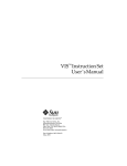
1.3 Component Overview
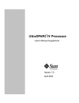
Figure 1-1 shows a block diagram of the UltraSPARC processor.
Prefetch and Dispatch Unit (PDU)
Instruction Cache and Buffer
Grouping Logic
Memory Management Unit (MMU)
iTLB
dTLB
Integer Reg and Annex
Load / Store Unit (LSU)
Integer Execution Unit (IEU)
Data
Cache
Load
Buffer
Store
Buffer
Floating Point Unit (FPU)
FP Multiply
FP
Reg
External Cache Unit (ECU)
Ext.
Cache
RAM
FP Add
FP Divide
Graphics Unit (GRU)
Memory Interface Unit (MIU)
System Interconnect
Figure 1-1
UltraSPARC Block Diagram
The block diagram illustrates the following components:
•
•
•
Prefetch and Dispatch Unit (PDU), including logic for branch prediction
16Kb Instruction Cache (I-Cache)
Memory Management Unit (MMU), containing a 64-entry Instruction
Translation Lookaside Buffer (iTLB) and a 64-entry Data Translation
Lookaside Buffer (dTLB)
Sun Microelectronics
5
UltraSPARC User’s Manual
•
Integer Execution Unit (IEU) with two Arithmetic and Logic Units (ALUs)
•
Load/Store Unit (LSU) with a separate address generation adder
•
Load buffer and store buffer, decoupling data accesses from the pipeline
•
A 16Kb Data Cache (D-Cache)
•
Floating-Point Unit (FPU) with independent add, multiply, and divide/square
root sub-units
•
Graphics Unit (GRU) with two independent execution pipelines
•
External Cache Unit (ECU), controlling accesses to the External Cache
(E-Cache)
•
Memory Interface Unit (MIU), controlling accesses to main memory and I/O
space
1.3.1 Prefetch and Dispatch Unit (PDU)
The prefetch and dispatch unit fetches instructions before they are actually needed in the pipeline, so the execution units do not starve for instructions. Instructions can be prefetched from all levels of the memory hierarchy; that is, from the
instruction cache, the external cache, and main memory. In order to prefetch
across conditional branches, a dynamic branch prediction scheme is implemented
in hardware. The outcome of a branch is based on a two-bit history of the branch.
A “next field” associated with every four instructions in the instruction cache
(I-Cache) points to the next I-Cache line to be fetched. The use of the next field
makes it possible to follow taken branches and to provide nearly the same instruction bandwidth achieved while running sequential code. Prefetched instructions are stored in the Instruction Buffer until they are sent to the rest of the
pipeline; up to 12 instructions can be buffered.
1.3.2 Instruction Cache (I-Cache)
The instruction cache is a 16 Kbyte two-way set associative cache with 32 byte
blocks. The cache is physically indexed and contains physical tags. The set is predicted as part of the “next field;” thus, only the index bits of an address (13 bits,
which matches the minimum page size) are needed to address the cache. The
I-Cache returns up to 4 instructions from an 8-instruction-wide cache line.
Sun Microelectronics
6
1. UltraSPARC Basics
1.3.3 Integer Execution Unit (IEU)
The IEU contains the following components:
•
•
•
•
•
•
Two ALUs
A multi-cycle integer multiplier
A multi-cycle integer divider
Eight register windows
Four sets of global registers (normal, alternate, MMU, and interrupt globals)
The trap registers (See Table 1-2 for supported trap levels)
Table 1-2
Supported Trap Levels
UltraSPARC-I
UltraSPARC-II
MAXTL
4
4
Trap Levels
5
5
1.3.4 Floating-Point Unit (FPU)
The FPU is partitioned into separate execution units, which allows the
UltraSPARC processor to issue and execute two floating-point instructions per
cycle. Source and result data are stored in the 32-entry register file, where each
entry can contain a 32-bit value or a 64-bit value. Most instructions are fully pipelined, (with a throughput of one per cycle), have a latency of three, and are not
affected by the precision of the operands (same latency for single- or double-precision). The divide and square root instructions are not pipelined and take 12/22
cycles (single/double) to execute but they do not stall the processor. Other instructions, following the divide/square root can be issued, executed, and retired
to the register file before the divide/square root finishes. A precise exception
model is maintained by synchronizing the floating-point pipe with the integer
pipe and by predicting traps for long latency operations. See Section 7.3.1, “Precise Traps,” in The SPARC Architecture Manual, Version 9.
1.3.5 Graphics Unit (GRU)
UltraSPARC introduces a comprehensive set of graphics instructions that provide
fast hardware support for two-dimensional and three-dimensional image and
video processing, image compression, audio processing, etc. 16-bit and 32-bit partitioned add, boolean, and compare are provided. 8-bit and 16-bit partitioned
multiplies are supported. Single cycle pixel distance, data alignment, packing,
and merge operations are all supported in the GRU.
Sun Microelectronics
7
UltraSPARC User’s Manual
1.3.6 Memory Management Unit (MMU)
The MMU provides mapping between a 44-bit virtual address and a 41-bit physical address. This is accomplished through a 64-entry iTLB for instructions and a
64-entry dTLB for data; both TLBs are fully associative. UltraSPARC provides
hardware support for a software-based TLB miss strategy. A separate set of global registers is available to process MMU traps. Page sizes of 8Kb (13-bit offset),
64Kb (16-bit offset), 512Kb (19-bit offset), and 4Mb (22-bit offset) are supported.
1.3.7 Load/Store Unit (LSU)
The LSU is responsible for generating the virtual address of all loads and stores
(including atomics and ASI loads), for accessing the D-Cache, for decoupling
load misses from the pipeline through the Load Buffer, and for decoupling stores
through the Store Buffer. One load or one store can be issued per cycle.
1.3.8 Data Cache (D-Cache)
The D-Cache is a write-through, non-allocating, 16Kb direct-mapped cache with
two 16-byte sub-blocks per line. It is virtually indexed and physically tagged
(VIPT). The tag array is dual ported, so tag updates due to line fills do not collide
with tag reads for incoming loads. Snoops to the D-Cache use the second tag
port, so they do not delay incoming loads.
1.3.9 External Cache Unit (ECU)
The main role of the ECU is to handle I-Cache and D-Cache misses efficiently.
The ECU can handle one access per cycle to the External Cache (E-Cache). Accesses to the E-Cache are pipelined, which effectively makes the E-Cache part of
the instruction pipeline. Programs with large data sets can keep data in the
E-Cache and can schedule instructions with load latencies based on E-Cache latency. Floating-point code can use this feature to effectively hide D-Cache misses.
Table 1-5 on page 10 shows the E-Cache sizes that each UltraSPARC model supports. Regardless of model, however, the E-Cache line size is always 64 bytes.
UltraSPARC uses a MOESI (Modified, Own, Exclusive, Shared, Invalid) protocol
to maintain coherence across the system.
Sun Microelectronics
8
1. UltraSPARC Basics
Table 1-3
E-Cache Size
Supported E-Cache Sizes
UltraSPARC-I
UltraSPARC-II
512 Kb
✓
✓
1 Mb
✓
✓
2 Mb
✓
✓
4 Mb
✓
✓
8 Mb
✓
16 Mb
✓
The ECU provides overlap processing during load and store misses. For instance,
stores that hit the E-Cache can proceed while a load miss is being processed. The
ECU can process reads and writes indiscriminately, without a costly turn-around
penalty (only 2 cycles). Finally, the ECU handles snoops.
Block loads and block stores, which load/store a 64-byte line of data from memory to the floating-point register file, are also processed efficiently by the ECU,
providing high transfer bandwidth without polluting the E-Cache.
1.3.9.1 E-Cache SRAM Modes
Different UltraSPARC models support various E-Cache SRAM configurations using one or more SRAM “modes.” Table 1-5 shows the modes that each
UltraSPARC model supports. The modes are described below.
Table 1-4
SRAM Mode
1–1–1
2–2
Supported E-Cache SRAM Modes
UltraSPARC-I
UltraSPARC-II
✓
✓
✓
1–1–1 (Pipelined) Mode:
The E-Cache SRAMS have a cycle time equal to the processor cycle time. The
name “1–1–1” indicates that it takes one processor clock to send the address, one
to access the SRAM array, and one to return the E-Cache data. 1–1–1 mode has a
3 cycle pin-to-pin latency and provides the best possible E-Cache throughput.
2–2 (Register-Latched) Mode:
The E-Cache SRAMS have a cycle time equal to one-half the processor cycle time.
The name “2–2” indicates that it takes two processor clocks to send the address
and two clocks to access and return the E-Cache data. 2–2 mode has a 4 cycle pinto-pin latency, which provides lower E-Cache throughput at reduced cost.
Sun Microelectronics
9
UltraSPARC User’s Manual
1.3.10 Memory Interface Unit (MIU)
The MIU handles all transactions to the system controller; for example, external
cache misses, interrupts, snoops, writebacks, and so on. The MIU communicates
with the system at some model-dependent fraction of the UltraSPARC frequency.
Table 1-5 shows the possible ratios between the processor and system clock frequencies for each UltraSPARC model.
Table 1-5
Model-Dependent Processor : System Clock Frequency Ratios
Frequency Ratio
UltraSPARC-I
UltraSPARC-II
2:1
✓
✓
3:1
✓
✓
✓
4:1
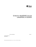
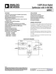
1.4 UltraSPARC Subsystem
Figure 1-2 shows a complete UltraSPARC subsystem, which consists of the
UltraSPARC processor, synchronous SRAM components for the E-Cache tags and
data, and two UltraSPARC Data Buffer (UDB) chips. The UDBs isolate the
E-Cache from the system, provide data buffers for incoming and outgoing system
transactions, and provide ECC generation and checking.
Tag Address
E-Cache Tag SRAM
Tag Data
Data Address
E-Cache Data SRAM
UltraSPARC
Processor
UDB
System
Data Bus
E-Cache Data
System
Address Bus
Figure 1-2
Sun Microelectronics
10
UltraSPARC Subsystem
2
Processor Pipeline
2.1 Introductions
UltraSPARC contains a 9-stage pipeline. Most instructions go through the pipeline in exactly 9 stages. The instructions are considered terminated after they go
through the last stage (W), after which changes to the processor state are irreversible. Figure 2-1 shows a simplified diagram of the integer and floating-point pipeline stages.
Integer Pipeline
Fetch
Decode
Floating-Point &
Graphics Pipeline
Figure 2-1
Group
Execute
Cache
N1
N2
Register
X1
X2
X3
N3
Write
UltraSPARC Pipeline Stages (Simplified)
Three additional stages are added to the integer pipeline to make it symmetrical
with the floating-point pipeline. This simplifies pipeline synchronization and exception handling. It also eliminates the need to implement a floating-point queue.
Floating-point instructions with a latency greater than three (divide, square root,
and inverse square root) behave differently than other instructions; the pipe is
“extended” when the instruction reaches stage N1. See Chapter 16, “Code Generation Guidelines” for more information. Memory operations are allowed to proceed asynchronously with the pipeline in order to support latencies longer than
the latency of the on-chip D-Cache.
Sun Microelectronics
11
UltraSPARC User’s Manual
2.2 Pipeline Stages
This section describes each pipeline stage in detail. Figure 2-2 illustrates the pipeline stages.
F/D
G
E
N1
C
N2
N3
W
Icc
VA
Tag Check
D-Cache
Tag
Hit
PA
D-Cache
Data
data bus
instruction bus
R
Figure 2-2
Sun Microelectronics
12
align
TLB
address bus
(Results in Annex)
IST_data
FP RF 32 x 64
Instruction Buffers
PDU
IU Register File
Annex
IEU
LSU
LDQ/STQ
SB
ECU
FPST_data
FP add
G ALU
FP mul
G mul
X1
FPU
GRU
X2
UltraSPARC Pipeline Stages (Detail)
X3
2. Processor Pipeline
2.2.1 Stage 1: Fetch (F) Stage
Prior to their execution, instructions are fetched from the Instruction Cache
(I-Cache) and placed in the Instruction Buffer, where eventually they will be selected to be executed. Accessing the I-Cache is done during the F Stage. Up to
four instructions are fetched along with branch prediction information, the predicted target address of a branch, and the predicted set of the target. The high
bandwidth provided by the I-Cache (4 instructions/cycle) allows UltraSPARC to
prefetch instructions ahead of time based on the current instruction flow and on
branch prediction. Providing a fetch bandwidth greater than or equal to the maximum execution bandwidth assures that, for well behaved code, the processor
does not starve for instructions. Exceptions to this rule occur when branches are
hard to predict, when branches are very close to each other, or when the I-Cache
miss rate is high.
2.2.2 Stage 2: Decode (D) Stage
After being fetched, instructions are pre-decoded and then sent to the Instruction
Buffer. The pre-decoded bits generated during this stage accompany the instructions during their stay in the Instruction Buffer. Upon reaching the next stage
(where the grouping logic lives) these bits speed up the parallel decoding of up
to 4 instructions.
While it is being filled, the Instruction Buffer also presents up to 4 instructions to
the next stage. A pair of pointers manage the Instruction Buffer, ensuring that as
many instructions as possible are presented in order to the next stage.
2.2.3 Stage 3: Grouping (G) Stage
The G Stage logic’s main task is to group and dispatch a maximum of four valid
instructions in one cycle. It receives a maximum of four valid instructions from
the Prefetch and Dispatch Unit (PDU), it controls the Integer Core Register File
(ICRF), and it routes valid data to each integer functional unit. The G Stage sends
up to two floating-point or graphics instructions out of the four candidates to the
Floating-Point and Graphics Unit (FGU). The G Stage logic is responsible for
comparing register addresses for integer data bypassing and for handling pipeline stalls due to interlocks.
Sun Microelectronics
13
UltraSPARC User’s Manual
2.2.4 Stage 4: Execution (E) Stage
Data from the integer register file is processed by the two integer ALUs during
this cycle (if the instruction group includes ALU operations). Results are computed and are available for other instructions (through bypasses) in the very next cycle. The virtual address of a memory operation is also calculated during the E
Stage, in parallel with ALU computation.
FLOATING-POINT AND GRAPHICS UNIT: The Register (R) Stage of the FGU. The
floating-point register file is accessed during this cycle. The instructions are also
further decoded and the FGU control unit selects the proper bypasses for the current instructions.
2.2.5 Stage 5: Cache Access (C) Stage
The virtual address of memory operations calculated in the E Stage is sent to the
tag RAM to determine if the access (load or store type) is a hit or a miss in the
D-Cache. In parallel the virtual address is sent to the data MMU to be translated
into a physical address. On a load when there are no other outstanding loads, the
data array is accessed so that the data can be forwarded to dependent instructions in the pipeline as soon as possible.
ALU operations executed in the E Stage generate condition codes in the C Stage.
The condition codes are sent to the PDU, which checks whether a conditional
branch in the group was correctly predicted. If the branch was mispredicted, earlier instructions in the pipe are flushed and the correct instructions are fetched.
The results of ALU operations are not modified after the E Stage; the data merely
propagates down the pipeline (through the annex register file), where it is available for bypassing for subsequent operations.
FLOATING-POINT AND GRAPHICS UNIT: The X1 Stage of the FGU. Floating-point and
graphics instructions start their execution during this stage. Instructions of latency one also finish their execution phase during the X1 Stage.
2.2.6 Stage 6: N1 Stage
A data cache miss/hit or a TLB miss/hit is determined during the N1 Stage. If a
load misses the D-Cache, it enters the Load Buffer. The access will arbitrate for
the E-Cache if there are no older unissued loads. If a TLB miss is detected, a trap
will be taken and the address translation is obtained through a software routine.
Sun Microelectronics
14
2. Processor Pipeline
The physical address of a store is sent to the Store Buffer during this stage. To
avoid pipeline stalls when store data is not immediately available, the store address and data parts are decoupled and sent to the Store Buffer separately.
FLOATING-POINT AND GRAPHICS
ues for most operations.
UNIT:
The X2 stage of the FGU. Execution contin-
2.2.7 Stage 7: N2 Stage
Most floating-point instructions finish their execution during this stage. After N2,
data can be bypassed to other stages or forwarded to the data portion of the Store
Buffer. All loads that have entered the Load Buffer in N1 continue their progress
through the buffer; they will reappear in the pipeline only when the data comes
back. Normal dependency checking is performed on all loads, including those in
the load buffer.
FLOATING-POINT
AND GRAPHICS UNIT:
The X3 stage of the FGU.
2.2.8 Stage 8: N3 Stage
UltraSPARC resolves traps at this stage.
2.2.9 Stage 9: Write (W) Stage
All results are written to the register files (integer and floating-point) during this
stage. All actions performed during this stage are irreversible. After this stage, instructions are considered terminated.
Sun Microelectronics
15
UltraSPARC User’s Manual
Sun Microelectronics
16
Cache Organization
3
3.1 Introduction
3.1.1 Level-1 Caches
UltraSPARC’s Level-1 D-Cache is virtually indexed, physically tagged (VIPT).
Virtual addresses are used to index into the D-Cache tag and data arrays while
accessing the D-MMU (that is, the dTLB). The resulting tag is compared against
the translated physical address to determine D-Cache hits.
A side-effect inherent in a virtual-indexed cache is address aliasing; this issue is
addressed in Section 5.2.1, “Address Aliasing Flushing,” on page 28.
UltraSPARC’s Level-1 I-Cache is physically indexed, physically tagged (PIPT).
The lowest 13 bits of instruction addresses are used to index into the I-Cache tag
and data arrays while accessing the I-MMU (that is, the iTLB). The resulting tag
is compared against the translated physical address to determine I-Cache hits.
3.1.1.1 Instruction Cache (I-Cache)
The I-Cache is a 16 Kb pseudo-two-way set-associative cache with 32-byte blocks.
The set is predicted based on the next fetch address; thus, only the index bits of
an address are necessary to address the cache (that is, the lowest 13 bits, which
matches the minimum page size of 8Kb). Instruction fetches bypass the instruction cache under the following conditions:
•
When the I-Cache enable or I-MMU enable bits in the LSU_Control_Register
are clear (see Section A.6, “LSU_Control_Register,” on page 306)
•
When the processor is in RED_state, or
Sun Microelectronics
17
UltraSPARC User’s Manual
•
When the I-MMU maps the fetch as noncacheable.
The instruction cache snoops stores from other processors or DMA transfers, but
it is not updated by stores in the same processor, except for block commit stores
(see Section 13.6.4, “Block Load and Store Instructions,” on page 230). The
FLUSH instruction can be used to maintain coherency. Block commit stores update the I-Cache but do not flush instructions that have already been prefetched
into the pipeline. A FLUSH, DONE, or RETRY instruction can be used to flush
the pipeline. For block copies that must maintain I-Cache coherency, it is more efficient to use block commit stores in the loop, followed by a single FLUSH instruction to flush the pipeline.
Note: The size of each I-Cache set is the same as the page size in UltraSPARC-I
and UltraSPARC-II; thus, the virtual index bits equal the physical index bits.
3.1.1.2 Data Cache (D-Cache)
The D-Cache is a write-through, nonallocating-on-write-miss 16-Kb direct
mapped cache with two 16-byte sub-blocks per line. Data accesses bypass the
data cache when the D-Cache enable bit in the LSU_Control_Register is clear (see
Section A.6, “LSU_Control_Register,” on page 306). Load misses will not allocate
in the D-Cache if the D-MMU enable bit in the LSU_Control_Register is clear or
the access is mapped by the D-MMU as virtual noncacheable.
Note: A noncacheable access may access data in the D-Cache from an earlier
cacheable access to the same physical block, unless the D-Cache is disabled.
Software must flush the D-Cache when changing a physical page from cacheable
to noncacheable (see Section 5.2, “Cache Flushing”).
3.1.2 Level-2 PIPT External Cache (E-Cache)
UltraSPARC’s level-2 (external) cache (the E-Cache) is physically indexed, physically tagged (PIPT). This cache has no references to virtual address and context
information. The operating system needs no knowledge of such caches after initialization, except for stable storage management and error handling.
Memory accesses must be cacheable in the E-Cache to allow use of UltraSPARC’s
ECC checking. As a result, there is no E-Cache enable bit in the
LSU_Control_Register.
Sun Microelectronics
18
3. Cache Organization
Instruction fetches bypass the E-Cache when:
•
•
•
The I-MMU is disabled, or
The processor is in RED_state, or
The access is mapped by the I-MMU as physically noncacheable
Data accesses bypass the E-Cache when:
•
•
The D-MMU enable bit (DM) in the LSU_Control_Register is clear, or
The access is mapped by the D-MMU as nonphysical cacheable (unless
ASI_PHYS_USE_EC is used).
The system must provide a noncacheable, ECC-less scratch memory for use of the
booting code until the MMUs are enabled.
The E-Cache is a unified, write-back, allocating, direct-mapped cache. The
E-Cache always includes the contents of the I-Cache and D-Cache. The E-Cache
size is model dependent (see Table 1-5 on page 10); its line size is 64 bytes.
Block loads and block stores, which load or store a 64-byte line of data from
memory to the floating-point register file, do not allocate into the E-Cache, in order to avoid pollution.
Sun Microelectronics
19
UltraSPARC User’s Manual
Sun Microelectronics
20
Overview of the MMU
4
4.1 Introduction
This chapter describes the UltraSPARC Memory Management Unit as it is seen by
the operating system software. The UltraSPARC MMU conforms to the requirements set forth in The SPARC Architecture Manual, Version 9.
Note: The UltraSPARC MMU does not conform to the SPARC-V8 Reference
MMU Specification. In particular, the UltraSPARC MMU supports a 44-bit virtual
address space, software TLB miss processing only (no hardware page table walk),
simplified protection encoding, and multiple page sizes. All of these differ from
features required of SPARC-V8 Reference MMUs.
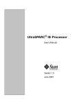
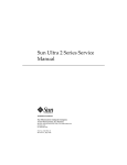
4.2 Virtual Address Translation
The UltraSPARC MMU supports four page sizes: 8 Kb, 64 Kb, 512 Kb, and 4 Mb.
It supports a 44-bit virtual address space, with 41 bits of physical address. During
each processor cycle the UltraSPARC MMU provides one instruction and one
data virtual-to-physical address translation. In each translation, the virtual page
number is replaced by a physical page number, which is concatenated with the
page offset to form the full physical address, as illustrated in Figure 4-1 on page
22. (This figure shows the full 64-bit virtual address, even though UltraSPARC
supports only 44 bits of VA.)
Sun Microelectronics
21
UltraSPARC User’s Manual
8K-byte Virtual Page Number
63
Page Offset
13 12
MMU
8K-byte Physical Page Number
Page Offset
13 12
40
VA
0
64K-byte Virtual Page Number
PA
0
Page Offset
16 15
63
8 Kb
VA
0
64 Kb
MMU
64K-byte Physical Page Number
Page Offset
16 15
40
512K-byte Virtual Page Number
63
MMU
Page Offset
19 18
512K-byte PPN
40
VA
0
Page Offset
19 18
4M-byte Virtual Page Number
63
PA
0
512 Kb
PA
0
Page Offset
22 21
VA
0
4 Mb
MMU
4M-byte PPN
40
Figure 4-1
Page Offset
22 21
PA
0
Virtual-to-physical Address Translation for all Page Sizes
UltraSPARC implements a 44-bit virtual address space in two equal halves at the
extreme lower and upper portions of the full 64-bit virtual address space. Virtual
addresses between 0000 0800 0000 000016 and FFFF F7FF FFFF FFFF16, inclusive,
are termed “out of range” for UltraSPARC and are illegal. (In other words, virtual
address bits VA<63:43> must be either all zeros or all ones.) Figure 4-2 on page 23
illustrates the UltraSPARC virtual address space.
Sun Microelectronics
22
4. Overview of the MMU
FFFF FFFF FFFF FFFF
FFFF F800 0000 0000
FFFF F7FF FFFF FFFF
Out of Range VA
(VA “Hole”)
0000 0800 0000 0000
0000 07FF FFFF FFFF
0000 0000 0000 0000
Figure 4-2
UltraSPARC’s 44-bit Virtual Address Space, with Hole (Same as Figure 14-2)
Note: Throughout this document, when virtual address fields are specified as
64-bit quantities, they are assumed to be sign-extended based on VA<43>.
The operating system maintains translation information in a data structure called
the Software Translation Table. The I- and D-MMU each contain a hardware
Translation Lookaside Buffer (iTLB and dTLB); these act as independent caches of
the Software Translation Table, providing one-cycle translation for the more frequently accessed virtual pages.
Figure 4-3 on page 24 shows a general software view of the UltraSPARC MMU.
The TLBs, which are part of the MMU hardware, are small and fast. The Software
Translation Table, which is kept in memory, is likely to be large and complex. The
Translation Storage Buffer (TSB), which acts like a direct-mapped cache, is the interface between the two. The TSB can be shared by all processes running on a
processor, or it can be process specific. The hardware does not require any particular scheme.
The term “TLB hit” means that the desired translation is present in the MMU’s
on-chip TLB. The term “TLB miss” means that the desired translation is not
present in the MMU’s on-chip TLB. On a TLB miss the MMU immediately traps
to software for TLB miss processing. The TLB miss handler has the option of filling the TLB by any means available, but it is likely to take advantage of the TLB
miss support features provided by the MMU, since the TLB miss handler is time
critical code. Hardware support is described in Section 6.3.1, “Hardware Support
for TSB Access,” on page 45.
Sun Microelectronics
23
UltraSPARC User’s Manual
Translation
Translation
Software
Look-aside
Storage
Translation
Buffers
Buffer
Table
MMU
Memory
O/S Data Structure
Figure 4-3
Software View of the UltraSPARC MMU
Aliasing between pages of different size (when multiple VAs map to the same
PA) may take place, as with the SPARC-V8 Reference MMU. The reverse case,
when multiple mappings from one VA/context to multiple PAs produce a multiple TLB match, is not detected in hardware; it produces undefined results.
Note: The hardware ensures the physical reliability of the TLB on multiple
matches.
Sun Microelectronics
24
Section II — Going Deeper
5.
Cache and Memory Interactions ......................................................
27
6.
MMU Internal Architecture ...............................................................
41
7.
UltraSPARC External Interfaces .......................................................
73
8.
Address Spaces, ASIs, ASRs, and Traps .......................................... 145
9.
Interrupt Handling ............................................................................. 161
10. Reset and RED_state .......................................................................... 169
11. Error Handling .................................................................................... 175
Sun Microelectronics
25
UltraSPARC User’s Manual
Sun Microelectronics
26
5
Cache and Memory Interactions
5.1 Introduction
This chapter describes various interactions between the caches and memory, and
the management processes that an operating system must perform to maintain
data integrity in these cases. In particular, it discusses:
•
When and how to invalidate one or more cache entries
•
The differences between cacheable and non-cacheable accesses
•
The ordering and synchronization of memory accesses
•
Accesses to addresses that cause side effects (I/O accesses)
•
Non-faulting loads
•
Instruction prefetching
•
Load and store buffers
This chapter only address coherence in a uniprocessor environment. For more information about coherence in multi-processor environments, see Chapter 15,
“SPARC-V9 Memory Models.”
5.2 Cache Flushing
Data in the level-1 (read-only or write-through) caches can be flushed by invalidating the entry in the cache. Modified data in the level-2 (writeback) cache must
be written back to memory when flushed.
Sun Microelectronics
27
UltraSPARC User’s Manual
Cache flushing is required in the following cases:
I-Cache:
Flush is needed before executing code that is modified by a local store instruction
other than block commit store, see Section 3.1.1.1, “Instruction Cache (I-Cache).”
This is done with the FLUSH instruction or using ASI accesses. See Section A.7,
“I-Cache Diagnostic Accesses,” on page 309. When ASI accesses are used, software must ensure that the flush is done on the same processor as the stores that
modified the code space.
D-Cache:
Flush is needed when a physical page is changed from (virtually) cacheable to
(virtually) noncacheable, or when an illegal address alias is created (see Section
5.2.1, “Address Aliasing Flushing,” on page 28). This is done with a displacement
flush (see Section 5.2.3, “Displacement Flushing,” on page 29) or using ASI
accesses. See Section A.8, “D-Cache Diagnostic Accesses,” on page 314.
E-Cache:
Flush is needed for stable storage. Examples of stable storage include batterybacked memory and transaction logs. This is done with either a displacement
flush (see Section 5.2.3, “Displacement Flushing,” on page 29) or a store with
ASI_BLK_COMMIT_{PRIMARY,SECONDARY}. Flushing the E-Cache will flush
the corresponding blocks from the I- and D-Caches, because UltraSPARC maintains inclusion between the external and internal caches. See Section 5.2.2, “Committing Block Store Flushing,” on page 29.
5.2.1 Address Aliasing Flushing
A side-effect inherent in a virtual-indexed cache is illegal address aliasing. Aliasing
occurs when multiple virtual addresses map to the same physical address. Since
UltraSPARC’s D-Cache is indexed with the virtual address bits and is larger than
the minimum page size, it is possible for the different aliased virtual addresses to
end up in different cache blocks. Such aliases are illegal because updates to one
cache block will not be reflected in aliased cache blocks.
Normally, software avoids illegal aliasing by forcing aliases to have the same address bits (virtual color) up to an alias boundary. For UltraSPARC, the minimum
alias boundary is 16Kb; this size may increase in future designs. When the alias
boundary is violated, software must flush the D-Cache if the page was virtual
cacheable. In this case, only one mapping of the physical page can be allowed in
the D-MMU at a time. Alternatively, software can turn off virtual caching of illegally aliased pages. This allows multiple mappings of the alias to be in the
D-MMU and avoids flushing the D-Cache each time a different mapping is referenced.
Sun Microelectronics
28
5. Cache and Memory Interactions
Note: A change in virtual color when allocating a free page does not require a
D-Cache flush, because the D-Cache is write-through.
5.2.2 Committing Block Store Flushing
In UltraSPARC, stable storage must be implemented by software cache flush.
Data that is present and modified in the E-Cache must be written back to the stable storage.
UltraSPARC implements two ASIs (ASI_BLK_COMMIT_{PRIMARY,SECONDARY}) to perform these writebacks efficiently when software can ensure exclusive
write access to the block being flushed. Using these ASIs, software can write back
data from the floating-point registers to memory and invalidate the entry in the
cache. The data in the floating-point registers must first be loaded by a block load
instruction. A MEMBAR #Sync instruction is needed to ensure that the flush is
complete. See also Section 13.6.4, “Block Load and Store Instructions,” on page
230.
5.2.3 Displacement Flushing
Cache flushing also can be accomplished by a displacement flush. This is done by
reading a range of read-only addresses that map to the corresponding cache line
being flushed, forcing out modified entries in the local cache. Care must be taken
to ensure that the range of read-only addresses is mapped in the MMU before
starting a displacement flush, otherwise the TLB miss handler may put new data
into the caches.
Note: Diagnostic ASI accesses to the E-Cache can be used to invalidate a line,
but they are generally not an alternative to displacement flushing. Modified data
in the E-Cache will not be written back to memory using these ASI accesses. See
Section A.9, “E-Cache Diagnostics Accesses,” on page 315.
5.3 Memory Accesses and Cacheability
Note: Atomic load-store instructions are treated as both a load and a store; they
can be performed only in cacheable address spaces.
Sun Microelectronics
29
UltraSPARC User’s Manual
5.3.1 Coherence Domains
Two types of memory operations are supported in UltraSPARC: cacheable and
noncacheable accesses, as indicated by the page translation. Cacheable accesses
are inside the coherence domain; noncacheable accesses are outside the coherence
domain.
SPARC-V9 does not specify memory ordering between cacheable and noncacheable accesses. In TSO mode, UltraSPARC maintains TSO ordering, regardless of
the cacheability of the accesses. For SPARC-V9 compatibility while in PSO or
RMO mode, a MEMBAR #Lookaside should be used between a store and a subsequent load to the same noncacheable address. See Section 8, “Memory Models,”
in The SPARC Architecture Manual, Version 9 for more information about the
SPARC-V9 memory models.
Note: On UltraSPARC, a MEMBAR #Lookaside executes more efficiently than
a MEMBAR #StoreLoad.
5.3.1.1 Cacheable Accesses
Accesses that fall within the coherence domain are called cacheable accesses.
They are implemented in UltraSPARC with the following properties:
•
•
•
Data resides in real memory locations.
They observe supported cache coherence protocol(s).
The unit of coherence is 64 bytes.
5.3.1.2 Non-Cacheable and Side-Effect Accesses
Accesses that are outside the coherence domain are called noncacheable accesses.
Some of these memory (-mapped) locations may have side-effects when accessed.
They are implemented in UltraSPARC with the following properties:
•
•
Data may or may not reside in real memory locations.
•
•
They may not observe supported cache coherence protocol(s).
Accesses may result in program-visible side-effects; for example, memorymapped I/O control registers in a UART may change state when read.
The smallest unit in each transaction is a single byte.
Sun Microelectronics
30
5. Cache and Memory Interactions
Noncacheable accesses with the E-bit set (that is, those having side-effects) are all
strongly ordered with respect to other noncacheable accesses with the E-bit set. In
addition, store buffer compression is disabled for these accesses. Speculative
loads with the E-bit set cause a data_access_exception trap (with SFSR.FT=2, speculative load to page marked with E-bit).
Note:
The side-effect attribute does not imply noncacheability.
5.3.1.3 Global Visibility and Memory Ordering
A memory access is considered globally visible when it has been acknowledged
by the system. In order to ensure the correct ordering between the cacheable and
noncacheable domains, explicit memory synchronization is needed in the form of
MEMBARs or atomic instructions. Code Example 5-1 illustrates the issues involved in mixing cacheable and noncacheable accesses.
Code Example 5-1 Memory Ordering and MEMBAR Examples
Assume that all accesses go to non-side-effect memory locations.
Process A:
While (1)
{
Store D1:data produced
1
MEMBAR #StoreStore (needed in PSO, RMO)
Store F1:set flag
While F1 is set (spin on flag)
Load F1
2
MEMBAR #LoadLoad | #LoadStore (needed in RMO)
Load D2
}
Process B:
While (1)
{
While F1 is cleared (spin on flag)
Load F1
2
MEMBAR #LoadLoad | #LoadStore (needed in RMO)
Load D1
Store D2
1
MEMBAR #StoreStore (needed in PSO, RMO)
Store F1:clear flag
}
Sun Microelectronics
31
UltraSPARC User’s Manual
Note: A MEMBAR #MemIssue or MEMBAR #Sync is needed if ordering of
cacheable accesses following noncacheable accesses must be maintained in PSO
or RMO.
Due to load and store buffers implemented in UltraSPARC, the above example
may not work in PSO and RMO modes without the MEMBARs shown in the program segment.
In TSO mode, loads and stores (except block stores) cannot pass earlier loads, and
stores cannot pass earlier stores; therefore, no MEMBAR is needed.
In PSO mode, loads are completed in program order, but stores are allowed to
pass earlier stores; therefore, only the MEMBAR at #1 is needed between updating data and the flag.
In RMO mode, there is no implicit ordering between memory accesses; therefore,
the MEMBARs at both #1 and #2 are needed.
5.3.2 Memory Synchronization: MEMBAR and FLUSH
The MEMBAR (STBAR in SPARC-V8) and FLUSH instructions are provide for explicit control of memory ordering in program execution. MEMBAR has several
variations; their implementations in UltraSPARC are described below. See Section
A.31, “Memory Barrier,” Section 8.4.3, “The MEMBAR Instruction,” and Section J,
“Programming With the Memory Models,” in The SPARC Architecture Manual,
Version 9 for more information.
5.3.2.1 MEMBAR #LoadLoad
Forces all loads after the MEMBAR to wait until all loads before the MEMBAR
have reached global visibility.
5.3.2.2 MEMBAR #StoreLoad
Forces all loads after the MEMBAR to wait until all stores before the MEMBAR
have reached global visibility.
5.3.2.3 MEMBAR #LoadStore
Forces all stores after the MEMBAR to wait until all loads before the MEMBAR
have reached global visibility.
Sun Microelectronics
32
5. Cache and Memory Interactions
5.3.2.4 MEMBAR #StoreStore and STBAR
Forces all stores after the MEMBAR to wait until all stores before the MEMBAR
have reached global visibility.
Note: STBAR has the same semantics as MEMBAR #StoreStore; it is included
for SPARC-V8 compatibility.
Note: The above four MEMBARs do not guarantee ordering between cacheable
accesses after noncacheable accesses.
5.3.2.5 MEMBAR #Lookaside
SPARC-V9 provides this variation for implementations having virtually tagged
store buffers that do not contain information for snooping.
Note: For SPARC-V9 compatibility, this variation should be used before issuing
a load to an address space that cannot be snooped.
5.3.2.6 MEMBAR #MemIssue
Forces all outstanding memory accesses to be completed before any memory access instruction after the MEMBAR is issued. It must be used to guarantee ordering of cacheable accesses following non-cacheable accesses. For example, I/O
accesses must be followed by a MEMBAR #MemIssue before subsequent cacheable stores; this ensures that the I/O accesses reach global visibility before the
cacheable stores after the MEMBAR.
Note: MEMBAR #MemIssue is different from the combination of MEMBAR
#LoadLoad | #LoadStore | #StoreLoad | #StoreStore. MEMBAR
#MemIssue orders cacheable and noncacheable domains; it prevents memory
accesses after it from issuing until it completes.
5.3.2.7 MEMBAR #Sync (Issue Barrier)
Forces all outstanding instructions and all deferred errors to be completed before
any instructions after the MEMBAR are issued.
Sun Microelectronics
33
UltraSPARC User’s Manual
Note: MEMBAR #Sync is a costly instruction; unnecessary usage may result in
substantial performance degradation.
5.3.2.8 Self-Modifying Code (FLUSH)
The SPARC-V9 instruction set architecture does not guarantee consistency between code and data spaces. A problem arises when code space is dynamically
modified by a program writing to memory locations containing instructions. LISP
programs and dynamic linking require this behavior. SPARC-V9 provides the
FLUSH instruction to synchronize instruction and data memory after code space
has been modified.
In UltraSPARC, a FLUSH behaves like a store instruction for the purpose of
memory ordering. In addition, all instruction (pre-)fetch buffers are invalidated.
The issue of the FLUSH instruction is delayed until previous (cacheable) stores
are completed. Instruction (pre-)fetch resumes at the instruction immediately after the FLUSH.
5.3.3 Atomic Operations
SPARC-V9 provides three atomic instructions to support mutual exclusion. These
instructions behave like both a load and a store, but the operations are carried out
indivisibly. Atomic instructions may be used only in the cacheable domain.
An atomic access with a restricted ASI in unprivileged mode (PSTATE.PRIV=0)
causes a privileged_action trap. An atomic access with a noncacheable address causes a data_access_exception trap (with SFSR.FT=4, atomic to page marked noncacheable). An atomic access with an unsupported ASI causes a
data_access_exception trap (with SFSR.FT=8, illegal ASI value or virtual address).
Table 5-1 lists the ASIs that support atomic accesses.
Table 5-1
ASIs that Support SWAP, LDSTUB, and CAS
ASI Name
Access
ASI_NUCLEUS{_LITTLE}
Restricted
ASI_AS_IF_USER_PRIMARY{_LITTLE}
Restricted
ASI_AS_IF_USER_SECONDARY{_LITTLE}
Restricted
ASI_PRIMARY{_LITTLE}
Unrestricted
ASI_SECONDARY{_LITTLE}
Unrestricted
ASI_PHYS_USE_EC{_LITTLE}
Unrestricted
Sun Microelectronics
34
5. Cache and Memory Interactions
Note: Atomic accesses with non-faulting ASIs are not allowed, because these
ASIs have the load-only attribute.
5.3.3.1 SWAP Instruction
SWAP atomically exchanges the lower 32 bits in an integer register with a word
in memory. This instruction is issued only after store buffers are empty. Subsequent loads interlock on earlier SWAPs. A cache miss will allocate the corresponding line.
Note: If a page is marked as virtually-non-cacheable but physically cacheable,
allocation is done to the E-Cache only.
5.3.3.2 LDSTUB Instruction
LDSTUB behaves like SWAP, except that it loads a byte from memory into an integer register and atomically writes all ones (FF16) into the addressed byte.
5.3.3.3 Compare and Swap (CASX) Instruction
Compare-and-swap combines a load, compare, and store into a single atomic instruction. It compares the value in an integer register to a value in memory; if
they are equal, the value in memory is swapped with the contents of a second integer register. All of these operations are carried out atomically; in other words,
no other memory operation may be applied to the addressed memory location
until the entire compare-and-swap sequence is completed.
5.3.4 Non-Faulting Load
A non-faulting load behaves like a normal load, except that:
•
It does not allow side-effect access. An access with the E-bit set causes a
data_access_exception trap (with SFSR.FT=2, Speculative Load to page marked
E-bit).
•
It can be applied to a page with the NFO-bit set; other types of accesses will
cause a data_access_exception trap (with SFSR.FT=1016, Normal access to page
marked NFO).
Sun Microelectronics
35
UltraSPARC User’s Manual
Non-faulting loads are issued with ASI_PRIMARY_NO_FAULT{_LITTLE}, or
ASI_SECONDARY_NO_FAULT{_LITTLE}. A store with a NO_FAULT ASI causes
a data_access_exception trap (with SFSR.FT=8, Illegal RW).
When a non-faulting load encounters a TLB miss, the operating system should attempt to translate the page. If the translation results in an error (for example, address out of range), a 0 is returned and the load completes silently.
Typically, optimizers use non-faulting loads to move loads before conditional
control structures that guard their use. This technique potentially increases the
distance between a load of data and the first use of that data, in order to hide latency; it allows for more flexibility in code scheduling. It also allows for improved performance in certain algorithms by removing address checking from
the critical code path.
For example, when following a linked list, non-faulting loads allow the null
pointer to be accessed safely in a read-ahead fashion if the OS can ensure that the
page at virtual address 016 is accessed with no penalty. The NFO (non-fault access
only) bit in the MMU marks pages that are mapped for safe access by non-faulting loads, but can still cause a trap by other, normal accesses. This allows programmers to trap on wild pointer references (many programmers count on an
exception being generated when accessing address 016 to debug code) while benefitting from the acceleration of non-faulting access in debugged library routines.
5.3.5 PREFETCH Instructions
Table 5-2 shows which UltraSPARC models support the PREFETCH{A} instructions.
Table 5-2
PREFETCH{A} Instruction Support
UltraSPARC-I
PREFETCH{A}
UltraSPARC-II
✓
UltraSPARC models that do not support PREFETCH treat it as a NOP.
5.3.5.1 PREFETCH Behavior and Limitations
UltraSPARC processors that do support PREFETCH behave in the following
ways:
•
All PREFETCH instructions are enqueued on the load buffer, except as noted
below.
Sun Microelectronics
36
5. Cache and Memory Interactions
•
Some conditions, noted below, cause an otherwise supported PREFETCH to
be treated as a NOP and removed from the load buffer when it reaches the
front of the queue.
•
No PREFETCH will cause a trap except:
• PREFETCH with fcn=5 .. 15 causes an illegal_instruction trap, as defined in The
SPARC Architecture Manual, Version 9.
• Watchpoint, as defined in Section A.5, “Watchpoint Support,” on page 304.
•
Any PREFETCHA that specifies an internal ASI in the following ranges is not
enqueued on the load buffer and is not executed:
• 4016..4F16, 5016..5F16, 6016..6F16, 7616, 7716
•
The following conditions cause a PREFETCH{A} to be treated as a NOP:
• PREFECTH with fcn=16..31, as defined in The SPARC Architecture Manual,
Version 9.
• A data_access_MMU_miss exception
• D-MMU disabled
• For PREFETCHA, any ASI other than the following 0416, 0C16, 1016, 1116,
1816, 1916, 8016..8316, 8816..8B16
• Attempt to PREFETCH to a noncacheable page
•
Alignment is not checked on PREFETCH{A}. The 5 least significant address
are ignored.
5.3.5.2 Implemented fcn Values
Table 5-3 lists the supported values for fcn and their meanings.
Table 5-3
fcn
PREFETCH{A} Variants
Prefetch Function
0
Prefetch for several reads
1
Prefetch for one read
2
Prefetch page
3
Prefetch for several writes
4
5..15
Prefetch for one write
illegal_instruction trap
16..31 NOP
For more information, including an enumeration of the bus transaction the each
fcn value causes, see Section 14.4.5, “PREFETCH{A} (Impdep #103, 117),” on page
248.
Sun Microelectronics
37
UltraSPARC User’s Manual
5.3.6 Block Loads and Stores
Block load and store instructions work like normal floating-point load and store
instructions, except that the data size (granularity) is 64 bytes per transfer. See
Section 13.6.4, “Block Load and Store Instructions,” on page 230 for a full description of the instructions.
5.3.7 I/O and Accesses with Side-effects
I/O locations may not behave with memory semantics. Loads and stores may
have side-effects; for example, a read access may clear a register or pop an entry
off a FIFO. A write access may set a register address port so that the next access
to that address will read or write a particular internal registers, etc. Such devices
are considered order sensitive. Also, such devices may only allow accesses of a
fixed size, so store buffer merging of adjacent stores or stores within a 16-byte region will cause an access error.
The UltraSPARC MMU includes an attribute bit (the E-Bit) in each page translation, which, when set, indicates that access to this page cause side effects. Accesses other than block loads or stores to pages that have this bit set have the
following behavior:
•
•
Noncacheable accesses are strongly ordered with respect to each other
•
•
Store buffer compression is disabled for noncacheable accesses.
•
Noncacheable loads with the E-bit set will not be issued until all previous
control transfers (including exceptions) are resolved.
Non-faulting loads are not allowed and will cause a data_access_exception trap
(with SFSR.FT = 2, speculative load to page marked E-bit).
A MEMBAR may be needed between side-effect and non-side-effect accesses
while in PSO and RMO modes.
5.3.8 Instruction Prefetch to Side-Effect Locations
UltraSPARC does instruction prefetching and follows branches that it predicts
will be taken. Addresses mapped by the I-MMU may be accessed even though
they are not actually executed by the program. Normally, locations with side effects or those that generate time-outs or bus errors will not be mapped by the
I-MMU, so prefetching will not cause problems. When running with the I-MMU
disabled, however, software must avoid placing data in the path of a control
transfer instruction target or sequentially following a trap or conditional branch
instruction. Data can be placed sequentially following the delay slot of a BA(,pt),
Sun Microelectronics
38
5. Cache and Memory Interactions
CALL, or JMPL instruction. Instructions should not be placed within 256 bytes of
locations with side effects. See Section 16.2.10, “Return Address Stack (RAS),” on
page 272 for other information about JMPLs and RETURNs.
5.3.9 Instruction Prefetch When Exiting RED_state
Exiting RED_state by writing 0 to PSTATE.RED in the delay slot of a JMPL is not
recommended. A noncacheable instruction prefetch may be made to the JMPL
target, which may be in a cacheable memory area. This may result in a bus error
on some systems, which will cause an instruction_access_error trap. The trap can be
masked by setting the NCEEN bit in the ESTATE_ERR_EN register to zero, but
this will mask all non-correctable error checking. To avoid this problem exit
RED_state with DONE or RETRY, or with a JMPL to a noncacheable target address.
5.3.10 UltraSPARC Internal ASIs
ASIs in the ranges 4616 .. 6F16 and 7616 ..7F16 are used for accessing internal
UltraSPARC states. Stores to these ASIs do not follow the normal memory model
ordering rules. Correct operation requires the following:
•
A MEMBAR #Sync is needed after an internal ASI store other than MMU
ASIs before the point that side effects must be visible. This MEMBAR must
precede the next load or noninternal store. The MEMBAR also must be in or
before the delay slot of a delayed control transfer instruction of any type. This
is necessary to avoid corrupting data.
•
A FLUSH, DONE, or RETRY is needed after an internal store to the MMU
ASIs (ASI 5016..5216, 5416..5F16) or to the IC bit in the LSU control register
before the point that side effects must be visible. Stores to D-MMU registers
other than the context ASIs may also use a MEMBAR #Sync. One of these
instructions must precede the next load or noninternal store. They also must
be in or before the delay slot of a delayed control transfer instruction. This is
necessary to avoid corrupting data.
5.4 Load Buffer
The load buffer allows the load and execution pipelines in UltraSPARC to be decoupled; thus, loads that cannot return data immediately will not stall the pipeline, but rather, will be buffered until they can return data. For example, when a
load misses the on-chip D-Cache and must access the E-Cache, the load will be
placed in the load buffer and the execution pipelines will continue moving as
Sun Microelectronics
39
UltraSPARC User’s Manual
long as they do not require the register that is being loaded. An instruction that
attempts to use the data that is being loaded by an instruction in the load buffer
is called a ‘use’ instruction.
The pipelines are not fully decoupled, because UltraSPARC still supports the notion of precise traps, and loads that are younger than a trapping instruction must
not execute, except in the case of deferred traps. Loads themselves can take precise traps, when exceptions are detected in the pipeline. For example, address
misalignment or access violations detected in the translation process will both be
reported as precise traps. However, when a load has a hardware problem on the
external bus (for example, a parity error), it will generate a deferred trap, since
younger instructions, unblocked by the D-Cache miss, could have been retired
and modified the machine state. This may result in termination of the user thread
or reset. UltraSPARC does not support recovery from such hardware errors, and
they are fatal. See Chapter 11.1 , “Error Handling.”
5.5 Store Buffer
All store operations (including atomic and STA instructions) and barriers or store
completion instructions (MEMBAR and STBAR) are entered into the Store Buffer.
5.5.1 Stores Delayed by Loads
The store buffer normally has lower priority than the load buffer when arbitrating for the D-Cache or E-Cache, since returning load data is usually more critical
than store completion. To ensure that stores complete in a finite amount of time
as required by SPARC-V9, UltraSPARC eventually will raise the store buffer priority above load buffer priority if the store buffer is continually locked out by
subsequent loads (other than internal ASI loads). Software using a load spin loop
to wait for a signal from another processor following a store that signals that processor will wait for the store to time out in the store buffer. For this type of code,
it is more efficient to put a MEMBAR #StoreLoad between the store and the
load spin loop.
5.5.2 Store Buffer Compression
Consecutive non-side-effect stores may be combined into aligned 16-byte entries
in the store buffer to improve store bandwidth. Cacheable stores can only be compressed with adjacent cacheable stores, Likewise, noncacheable stores can only be
compressed with adjacent noncacheable stores. In order to maintain strong ordering for I/O accesses, stores with the side-effect attribute (E-bit set) cannot be
combined with any other stores.
Sun Microelectronics
40
6
MMU Internal Architecture
6.1 Introduction
This chapter provides detailed information about the UltraSPARC Memory Management Unit. It describes the internal architecture of the MMU and how to program it.
6.2 Translation Table Entry (TTE)
The Translation Table Entry, illustrated in Figure 6-1, is the UltraSPARC equivalent of a SPARC-V8 page table entry; it holds information for a single page mapping. The TTE is broken into two 64-bit words, representing the tag and data of
the translation. Just as in a hardware cache, the tag is used to determine whether
there is a hit in the TSB. If there is a hit, the data is fetched by software.
G
—
63
62 61 60
V
Size NFO IE
63 62 61 60
Figure 6-1
G:
Context
—
48 47
Tag
VA_tag<63:22>
42 41
Soft2 Diag PA<40:13> Soft
59 58 50 49 41 40
13 12 7
0
L
CP
CV
E
P
W
G
6
5
4
3
2
1
0
Data
Translation Table Entry (TTE) (from TSB)
Global. If the Global bit is set, the Context field of the TTE is ignored
during hit detection. This allows any page to be shared among all (user
or supervisor) contexts running in the same processor. The Global bit is
duplicated in the TTE tag and data to optimize the software miss handler.
Context: The 13-bit context identifier associated with the TTE.
Sun Microelectronics
41
UltraSPARC User’s Manual
VA_tag<63:22>: Virtual Address Tag. The virtual page number. Bits 21 through 13
are not maintained in the tag, since these bits are used to index the
smallest direct-mapped TSB of 64 entries.
Note:
Software must sign-extend bits VA_tag<63:44> to form an in-range VA.
V:
Valid: If the Valid bit is set, the remaining fields of the TTE are
meaningful. Note that the explicit Valid bit is redundant with the
software convention of encoding an invalid TTE with an unused context.
The encoding of the context field is necessary to cause a failure in the TTE
tag comparison, while the explicit Valid bit in the TTE data simplifies the
TLB miss handler.
Size:
The page size of this entry, encoded as shown in the following table.
Table 6-1
Size Field Encoding (from TTE)
Size<1:0>
Page Size
00
8 Kb
01
64 Kb
10
512 Kb
11
4 Mb
NFO:
No-Fault-Only. If this bit is set, loads with
ASI_PRIMARY_NO_FAULT{_LITTLE},
ASI_SECONDARY_NO_FAULT{_LITTLE} are translated. Any other
access will trap with a data_access_exception trap (FT=1016). The NFO-bit
in the I-MMU is read as zero and ignored when written. If this bit is set
before loading the TTE into the TLB, the iTLB miss handler should
generate an error.
IE:
Invert Endianness. If this bit is set, accesses to the associated page are
processed with inverse endianness from what is specified by the
instruction (big-for-little and little-for-big). See Section 6.6, “ASI Value,
Context, and Endianness Selection for Translation,” on page 52 for
details. In the I-MMU this bit is read as zero and ignored when written.
Note: This bit is intended to be set primarily for noncacheable accesses. The
performance of cacheable accesses will be degraded as if the access had missed
the D-Cache.
Sun Microelectronics
42
6. MMU Internal Architecture
Soft<5:0>, Soft2<8:0>: Software-defined fields, provided for use by the operating
system. The Soft and Soft2 fields may be written with any value; they
read as zero.
Diag:
Used by diagnostics to access the redundant information held in the TLB
structure. Diag<0>=Used bit, Diag<3:1>=RAM size bits, Diag<6:4>=CAM
size bits. (Size bits are 3-bit encoded as 000=8K, 001=64K, 011=512K,
111=4M.) The size bits are read-only; the Used bit is read/write. All other
Diag bits are reserved.
PA<40:13>: The physical page number. Page offset bits for larger page sizes
(PA<15:13>, PA<18:13>, and PA<21:13> for 64Kb, 512Kb, and 4Mb pages,
respectively) are stored in the TLB and returned for a Data Access read,
but ignored during normal translation.
L:
Lock. If this bit is set, the TTE entry will be “locked down” when it is
loaded into the TLB; that is, if this entry is valid, it will not be replaced by
the automatic replacement algorithm invoked by an ASI store to the Data
In register. The lock bit has no meaning for an invalid entry. Arbitrary
entries may be locked down in the TLB. Software must ensure that at
least one entry is not locked when replacing a TLB entry, otherwise the
last TLB entry will be replaced.
CP, CV: The cacheable-in-physically-indexed-cache and cacheable-in-virtuallyindexed-cache bits determine the placement of data in UltraSPARC
caches, according to Table 6-2. The MMU does not operate on the
cacheable bits, but merely passes them through to the cache subsystem.
The CV-bit in the I-MMU is read as zero and ignored when written.
Table 6-2
Cacheable Field Encoding (from TSB)
Cacheable
{CP, CV}
0x
E:
Meaning of TTE When Placed in:
iTLB
(I-Cache PA-Indexed)
dTLB
(D-Cache VA-Indexed)
Non-cacheable
Non-cacheable
10
Cacheable E-Cache, I-Cache
Cacheable E-Cache only
11
Cacheable E-Cache, I-Cache
Cacheable E-Cache, D-Cache
Side-effect. If this bit is set, speculative loads and FLUSHes will trap for
addresses within the page, noncacheable memory accesses other than
block loads and stores are strongly ordered against other E-bit accesses,
and noncacheable stores are not merged. This bit should be set for pages
that map I/O devices having side-effects. Note, however, that the E-bit
does not prevent normal instruction prefetching. The E-bit in the I-MMU
is read as zero and ignored when written.
Sun Microelectronics
43
UltraSPARC User’s Manual
Note: The E-bit does not force an uncacheable access. It is expected, but not
required, that the CP and CV bits will be set to zero when the E-bit is set.
P:
Privileged. If the P bit is set, only the supervisor can access the page
mapped by the TTE. If the P bit is set and an access to the page is
attempted when PSTATE.PRIV=0, the MMU will signal an
instruction_access_exception or data_access_exception trap (FT=116).
W:
Writable. If the W bit is set, the page mapped by this TTE has write
permission granted. Otherwise, write permission is not granted and the
MMU will cause a data_access_protection trap if a write is attempted. The
W-bit in the I-MMU is read as zero and ignored when written.
G:
Global. This bit must be identical to the Global bit in the TTE tag. Similar
to the case of the Valid bit, the Global bit in the TTE tag is necessary for
the TSB hit comparison, while the Global bit in the TTE data facilitates
the loading of a TLB entry.
Compatibility Note:
Referenced and Modified bits are maintained by software. The Global, Privileged,
and Writable fields replace the 3-bit ACC field of the SPARC-V8 Reference MMU
Page Translation Entry.
6.3 Translation Storage Buffer (TSB)
The TSB is an array of TTEs managed entirely by software. It serves as a cache of
the Software Translation Table, used to quickly reload the TLB in the event of a
TLB miss. The discussion in this section assumes the use of the hardware support
for TSB access described in Section 6.3.1, “Hardware Support for TSB Access,” on
page 45, although the operating system is not required to make use of this support hardware.
Inclusion of the TLB entries in the TSB is not required; that is, translation information may exist in the TLB that is not present in the TSB.
The TSB is arranged as a direct-mapped cache of TTEs. The UltraSPARC MMU
provides precomputed pointers into the TSB for the 8 Kb and 64 Kb page TTEs.
In each case, N least significant bits of the respective virtual page number are
used as the offset from the TSB base address, with N equal to log base 2 of the
number of TTEs in the TSB.
A bit in the TSB register allows the TSB 64 Kb pointer to be computed for the case
of common or split 8 Kb/64 Kb TSB(s).
Sun Microelectronics
44
6. MMU Internal Architecture
No hardware TSB indexing support is provided for the 512 Kb and 4 Mb page
TTEs. Since the TSB is entirely software managed, however, the operating system
may choose to place these larger page TTEs in the TSB by forming the appropriate pointers. In addition, simple modifications to the 8 Kb and 64 Kb index pointers provided by the hardware allow formation of an M-way set-associative TSB,
multiple TSBs per page size, and multiple TSBs per process.
The TSB exists as a normal data structure in memory, and therefore may be
cached. Indeed, the speed of the TLB miss handler relies on the TSB accesses hitting the level-2 cache at a substantial rate. This policy may result in some conflicts with normal instruction and data accesses, but the dynamic sharing of the
level-2 cache resource should provide a better overall solution than that provided
by a fixed partitioning.
Figure 6-2 shows both the common and shared TSB organization. The constant N
is determined by the Size field in the TSB register; it may range from 512 to 64K.
Tag1 (8 bytes)
000016
N Lines in Common TSB
Data1 (8 bytes)
000816
TagN (8 bytes)
DataN (8 bytes)
Tag1 (8 bytes)
Data1 (8 bytes)
2N Lines in Split TSB
TagN (8 bytes)
Figure 6-2
DataN (8 bytes)
TSB Organization
6.3.1 Hardware Support for TSB Access
The MMU hardware provides services to allow the TLB miss handler to efficiently reload a missing TLB entry for an 8 Kb or 64 Kb page. These services include:
•
Formation of TSB Pointers based on the missing virtual address.
•
Formation of the TTE Tag Target used for the TSB tag comparison.
•
Efficient atomic write of a TLB entry with a single store ASI operation.
•
Alternate globals on MMU-signalled traps.
Sun Microelectronics
45
UltraSPARC User’s Manual
A typical TLB miss and refill sequence is as follows:
1.
A TLB miss causes either an instruction_access_MMU_miss or a
data_access_MMU_miss exception.
2.
The appropriate TLB miss handler loads the TSB Pointers and the TTE Tag
Target with loads from the MMU alternate space
3.
Using this information, the TLB miss handler checks to see if the desired
TTE exists in the TSB. If so, the TTE Data is loaded into the TLB Data In
register to initiate an atomic write of the TLB entry chosen by the
replacement algorithm.
4.
If the TTE does not exist in the TSB, the TLB miss handler jumps to a more
sophisticated (and slower) TSB miss handler.
The virtual address used in the formation of the pointer addresses comes from
the Tag Access register, which holds the virtual address and context of the load or
store responsible for the MMU exception. See Section 6.9, “MMU Internal Registers and ASI Operations,” on page 55. (Note that there are no separate physical
registers in UltraSPARC hardware for the Pointer registers, but rather they are
implemented through a dynamic re-ordering of the data stored in the Tag Access
and the TSB registers.)
Pointers are provided by hardware for the most common cases of 8 Kb and 64 Kb
page miss processing. These pointers give the virtual addresses where the 8 Kb
and 64 Kb TTEs would be stored if either is present in the TSB.
N is defined to be the TSB_Size field of the TSB register; it ranges from 0 to 7.
Note that TSB_Size refers to the size of each TSB when the TSB is split.
For a shared TSB (TSB register split field=0):
8K_POINTER = TSB_Base<63:13+N>
VA<21+N:13>
64K_POINTER = TSB_Base<63:13+N>
0000
VA<24+N:16>
0000
For a split TSB (TSB register split field=1):
8K_POINTER = TSB_Base<63:14+N>
64K_POINTER = TSB_Base<63:14+N>
0
VA<21+N:13>
1
VA<24+N:16>
0000
0000
For a more detailed description of the pointer logic with pseudo-code and hardware implementation, see Section 6.11.3, “TSB Pointer Logic Hardware Description,” on page 70.
Sun Microelectronics
46
6. MMU Internal Architecture
The TSB Tag Target (described in Section 6.9, “MMU Internal Registers and ASI
Operations,” on page 55) is formed by aligning the missing access VA (from the
Tag Access register) and the current context to positions found in the description
of the TTE tag. This allows an XOR instruction for TSB hit detection.
These items must be locked in the TLB to avoid an error condition: TLB-miss handler, TSB and linked data, asynchronous trap handlers and data.
These items must be locked in the TSB (not necessarily the TLB) to avoid an error
condition: TSB-miss handler and data, interrupt-vector handler and data.
6.3.2 Alternate Global Selection During TLB Misses
In the SPARC-V9 normal trap mode, the software is presented with an alternate
set of global registers in the integer register file. UltraSPARC provides an additional feature to facilitate fast handling of TLB misses. For the following traps, the
trap handler is presented with a special set of MMU globals: fast_{instruction,data}_access_MMU_miss, {instruction,data}_access_exception, and
fast_data_access_protection. The privileged_action and *mem_address_not_aligned traps
use the normal alternate global registers.
Compatibility Note:
The UltraSPARC MMU performs no hardware table walking. The MMU hardware never directly reads or writes the TSB.
6.4 MMU-Related Faults and Traps
Table 6-3 lists the traps recorded by the MMU.
Table 6-3
MMU Traps
Trap Name
fast_instruction_access_MMU_miss
instruction_access_exception
fast_data_access_MMU_miss
data_access_exception
fast_data_access_protection
privileged_action
*_watchpoint
*_mem_address_not_aligned
1
Trap Cause
iTLB miss
Several (see below)
dTLB miss
Several (see below)
Protection violation
Use of privileged ASI
Watchpoint hit
Misaligned mem op
Registers Updated
(Stored State in MMU)
I-Tag D-SFSR, D-Tag
I-SFSR
Access
SFAR
Access
✓
✓
✓1
✓
✓
✓
✓
✓
✓
✓
✓
Contents undefined if instruction_access_exception is due to virtual address out of range.
Sun Microelectronics
47
UltraSPARC User’s Manual
Note:
The fast_instruction_access_MMU_miss, fast_data_access_MMU_miss, and
fast_data_access_protection traps are generated instead of
instruction_access_MMU_miss, data_access_MMU_miss, and data_access_protection
traps, respectively.
6.4.1 Instruction_access_MMU_miss Trap
This trap occurs when the I-MMU is unable to find a translation for an instruction access; that is, when the appropriate TTE is not in the iTLB.
6.4.2 Instruction_access_exception Trap
This trap occurs when the I-MMU is enabled and one of the following happens:
•
The I-MMU detects a privilege violation for an instruction fetch; that is, an
attempted access to a privileged page when PSTATE.PRIV=0.
•
Virtual address out of range and PSTATE.AM is not set. See Section 14.1.6,
“44-bit Virtual Address Space,” on page 237. Note that the case of JMPL/
RETURN and branch-CALL-sequential are handled differently. The contents
of the I-Tag Access Register are undefined in this case, but are not needed by
software.
6.4.3 Data_access_MMU_miss Trap
This trap occurs when the MMU is unable to find a translation for a data access;
that is, when the appropriate TTE is not in the data TLB for a memory operation.
6.4.4 Data_access_exception Trap
This trap occurs when the D-MMU is enabled and one of the following happens:
(the D-MMU does not prioritize these)
•
The D-MMU detects a privilege violation for a data or FLUSH instruction
access; that is, an attempted access to a privileged page when
PSTATE.PRIV=0.
•
A speculative (non-faulting) load or FLUSH instruction issued to a page
marked with the side-effect (E-bit)=1.
•
An atomic instruction (including 128-bit atomic load) issued to a memory
address marked uncacheable in a physical cache; that is, with CP=0.
Sun Microelectronics
48
6. MMU Internal Architecture
•
•
•
An invalid LDA/STA ASI value, invalid virtual address, read to write-only
register, or write to read-only register, but not for an attempted user access to
a restricted ASI (see the privileged_action trap described below).
An access (including FLUSH) with an ASI other than
ASI_{PRIMARY,SECONDARY}_NO_FAULT{_LITTLE} to a page marked with
the NFO (no-fault-only) bit.
Virtual address out of range (including FLUSH) and PSTATE.AM is not set.
See Section 4.2, “Virtual Address Translation,” on page 21.
The data_access_exception trap also occurs when the D-MMU is disabled and one
the following occurs:
• Speculative (non-faulting) load or FLUSH instruction issued when
LSU_Control_Register.DP=0.
• An atomic instruction (including 128-bit atomic load) is issued using the
ASI_PHYS_BYPASS_EC_WITH_EBIT{_LITTLE} ASIs. In this case
SFSR.FT=0416.
6.4.5 Data_access_protection Trap
This trap occurs when the MMU detects a protection violation for a data access.
A protection violation is defined to be an attempted store to a page that does not
have write permission.
6.4.6 Privileged_action Trap
This trap occurs when an access is attempted using a restricted ASI while in nonprivileged mode (PSTATE.PRIV=0).
6.4.7 Watchpoint Trap
This trap occurs when watchpoints are enabled and the D-MMU detects a load or
store to the virtual or physical address specified by the VA Data Watchpoint Register
or the PA Data Watchpoint Register, respectively. See Section A.5, “Watchpoint Support,” on page 304.
6.4.8 Mem_address_not_aligned Trap
This trap occurs when a load, store, atomic, or JMPL/RETURN instruction with a
misaligned address is executed. The LSU signals this trap, but the D-MMU
records the fault information in the SFSR and SFAR.
Sun Microelectronics
49
UltraSPARC User’s Manual
6.5 MMU Operation Summary
Table 6-4 on page 51 summarizes the behavior of the D-MMU; Table 6-5 on page
51 summarizes the behavior of the I-MMU for normal (non-UltraSPARC-internal)
ASIs. In each case, for all conditions the behavior of the MMU is given by one of
the following abbreviations:
Abbrev
Meaning
OK
Normal Translation
DMISS
data_access_MMU_miss trap
DEXC
data_access_exception trap
DPROT
data_access_protection trap
IMISS
instruction_access_MMU_miss trap
IEXC
instruction_access_exception trap
The ASI is indicated by one the following abbreviations:
Abbrev
Meaning
NUC
ASI_NUCLEUS*
PRIM
Any ASI with PRIMARY translation, except *NO_FAULT”
SEC
Any ASI with SECONDARY translation, except *NO_FAULT”
PRIM_NF
ASI_PRIMARY_NO_FAULT*
SEC_NF
ASI_SECONDARY_NO_FAULT*
U_PRIM
ASI_AS_IF_USER_PRIMARY*
U_SEC
ASI_AS_IF_USER_SECONDARY*
BYPASS
ASI_PHYS_* and also other ASIs that require the MMU to perform a bypass operation
(such as D-Cache access)
Note: The “*_LITTLE” versions of the ASIs behave the same as the big-endian
versions with regard to the MMU table of operations.
Other abbreviations include “W” for the writable bit, “E” for the side-effect bit,
and “P” for the privileged bit.
The tables do not cover the following cases:
• Invalid ASIs, ASIs that have no meaning for the opcodes listed, or nonexistent ASIs; for example, ASI_PRIMARY_NO_FAULT for a store or atomic.
Also, access to UltraSPARC internal registers other than LDXA, LDFA, STDFA
or STXA, except for I-Cache diagnostic accesses other than LDDA, STDFA or
STXA. See Section 8.3.2, “UltraSPARC (Non-SPARC-V9) ASI Extensions,” on
page 147. The MMU signals a data_access_exception trap (FT=0816) for this
case.
Sun Microelectronics
50
6. MMU Internal Architecture
•
Attempted access using a restricted ASI in non-privileged mode. The MMU
signals a privileged_action exception for this case.
•
An atomic instruction (including 128-bit atomic load) issued to a memory
address marked uncacheable in a physical cache (that is, with CP=0),
including cases in which the D-MMU is disabled. The MMU signals a
data_access_exception trap (FT=0416) for this case.
•
A data access (including FLUSH) with an ASI other than
ASI_{PRIMARY,SECONDARY}_NO_FAULT{_LITTLE} to a page marked with
the NFO (no-fault-only) bit. The MMU signals a data_access_exception trap
(FT=1016) for this case.
•
Virtual address out of range (including FLUSH) and PSTATE.AM is not set.
The MMU signals a data_access_exception trap (FT=2016) for this case.
Table 6-4
D-MMU Operations for Normal ASIs
Condition
Opcode
PRIV
Mode
W
E=0
P=0
E=0
P=1
PRIM, SEC
—
DMISS
OK
PRIM_NF, SEC_NF
—
DMISS
OK
PRIM, SEC, NUC
—
DMISS
OK
OK
PRIM_NF, SEC_NF
—
DMISS
OK
DEXC
ASI
0
Load
1
Behavior
TLB
Miss
U_PRIM, U_SEC
FLUSH
—
—
Table 6-5
DEXC
OK
DEXC
DEXC
DEXC
DEXC
—
DMISS
OK
DEXC
OK
DEXC
DMISS
OK
DEXC
DEXC
DEXC
—
DMISS
OK
OK
DEXC
DEXC
0
DMISS
DPROT
DEXC
DPROT
DEXC
1
DMISS
OK
DEXC
OK
DEXC
PRIM, SEC, NUC
0
DMISS
1
DMISS
U_PRIM, U_SEC
0
DMISS
DPROT
DEXC
DPROT
DEXC
1
DMISS
OK
DEXC
OK
DEXC
1
0
Store or
Atomic
E=1
P=1
—
0
1
E=1
P=0
PRIM, SEC
DPROT
DPROT
OK
OK
0
BYPASS
—
privileged_action
1
BYPASS
—
Bypass. No traps when D-MMU enabled,
PRIV=1.
I-MMU Operations for Normal ASIs
Condition
Behavior
PRIV Mode
TLB Miss
P=0
0
IMISS
OK
1
IMISS
P=1
IEXC
OK
Sun Microelectronics
51
UltraSPARC User’s Manual
See Section 8.3, “Alternate Address Spaces,” on page 146 for a summary of the
UltraSPARC ASI map.
6.6 ASI Value, Context, and Endianness Selection for Translation
The MMU uses a two-step process to select the context for a translation:
1.
The ASI is determined (conceptually by the Integer Unit) from the
instruction, trap level, and the processor endian mode
2.
The context register is determined directly from the ASI.
The ASI value and endianness (little or big) are determined for the I-MMU and
D-MMU respectively according to Table 6-6 and Table 6-7 on page 53.
Note: The secondary context is never used to fetch instructions. The I-MMU
uses the value stored in the D-MMU Primary Context register when using the
Primary Context identifier; there is no I-MMU Primary Context register.
Note: The endianness of a data access is specified by three conditions: the ASI
specified in the opcode or ASI register, the PSTATE current little endian bit, and
the D-MMU invert endianness bit. The D-MMU invert endianness bit does not
affect the ASI value recorded in the SFSR, but does invert the endianness that is
otherwise specified for the access.
Note: The D-MMU Invert Endianness (IE) bit inverts the endianness for all
accesses to translating ASIs, including LD/ST/Atomic alternates that have
specified an ASI. That is, LDXA [%g1]ASI_PRIMARY_LITTLE will be big-endian
if the IE bit is on. Accesses to non-translating ASIs are not affected by the
D-MMU’s IE bit. See Section 8.3, “Alternate Address Spaces,” on page 146 for
information about non-translating ASIs
Sun Microelectronics
52
6. MMU Internal Architecture
Table 6-6
ASI Mapping for Instruction Accesses
Condition for Instruction Access
Table 6-7
Resulting Action
PSTATE.TL
Endianness
0
Big
ASI Value (in SFSR)
ASI_PRIMARY
>0
Big
ASI_NUCLEUS
ASI Mapping for Data Accesses
Condition for Data Access
PSTATE.
TL
Opcode
Access Processed with:
PSTATE.
CLE
D-MMU.
IE
0
0
1
LD/ST/Atomic/FLUSH
0
>0
1
LD/ST/Atomic Alternate
with specified ASI not
Don’t Care
ending in “_LITTLE”
Don’t Care
LD/ST/Atomic Alternate
with specified ASI
Don’t Care
ending in ‘_LITTLE”
Don’t Care
ASI Value
(Recorded in SFSR)
Endianness
0
Big
1
Little
0
Little
1
Big
0
Big
1
Little
0
Little
1
Big
0
Big1
1
Little1
0
Little
1
Big
ASI_PRIMARY
ASI_PRIMARY_LITTLE
ASI_NUCLEUS
ASI_NUCLEUS_LITTLE
Specified ASI value from immediate
field in opcode or ASI register
Specified ASI value from immediate
field in opcode or ASI register
1 Accesses to non-translating ASIs are always made in “big endian” mode, regardless of the setting of D-MMU.IE. See Section 8.3,
“Alternate Address Spaces,” on page 146 for information about non-translating ASIs.
The context register used by the data and instruction MMUs is determined from
the following table. A comprehensive list of ASI values can be found in the ASI
map in Section 8.3, “Alternate Address Spaces,” on page 146. The context register
selection is not affected by the endianness of the access.
Table 6-8
I-MMU and D-MMU Context Register Usage
ASI Value
Context Register
ASI_*NUCLEUS*a
Nucleus (000016 hard-wired)
ASI_*PRIMARY*b
Primary
ASI_*SECONDARY*c
Secondary
All other ASI values
(Not applicable, no translation)
a. Any ASI name containing the string “NUCLEUS”.
b. Any ASI name containing the string “PRIMARY”.
c. Any ASI name containing the string “SECONDARY”.
Sun Microelectronics
53
UltraSPARC User’s Manual
6.7 MMU Behavior During Reset, MMU Disable, and RED_state
During global reset of the UltraSPARC CPU, the following actions occur:
•
•
•
No change occurs in any block of the D-MMU.
•
The I-MMU and D-MMU Enable bits in the LSU Control Register (see Section
A.6, “LSU_Control_Register,” on page 306) are set to zero.
No change occurs in the datapath or TLB blocks of the I-MMU.
The I-MMU resets its internal state machine to normal (non-suspended)
operation.
On entering RED_state, the following action occurs:
•
The I-MMU and D-MMU Enable bits in the LSU_Control_Register are set to
zero.
Either MMU is defined to be disabled when its respective MMU Enable bit equals
0; also, the I-MMU is disabled whenever the CPU is in RED_state. The D-MMU is
enabled or disabled solely by the state of the D-MMU Enable bit.
When the D-MMU is disabled it truncates all accesses, behaving as if
ASI_PHYS_BYPASS_EC_WITH_EBIT had been used, notably with side effect bit
(E-bit)=1, P=0 and CP=0. Other attribute bit settings can be found in Section 6.10,
“MMU Bypass Mode,” on page 68. However, if a bypass ASI is used while the DMMU is disabled, the bypass operation behaves as it does when the D-MMU is
enabled; that is, the access is processed with the E and CP bits as specified by the
bypass ASI.
When the I-MMU is disabled, it truncates all instruction accesses and passes the
physically-cacheable bit (CP=0) to the cache system. The access will not generate
an instruction_access_exception trap.
When disabled, both the I-MMU and D-MMU correctly perform all LDXA and
STXA operations to internal registers, and traps are signalled just as if the MMU
were enabled. For instance, if a *NO_FAULT load is issued when the D-MMU is
disabled, the D-MMU signals a data_access_exception trap (FT=0216), since accesses when the D-MMU is disabled have E=1.
Note: While the D-MMU is disabled, data in the D-Cache can be accessed only
using load and store alternates to the UltraSPARC internal D-Cache access ASI.
Normal loads and stores bypass the D-Cache. Data in the D-Cache cannot be
accessed using load or store alternates that use ASI_PHYS_*.
Sun Microelectronics
54
6. MMU Internal Architecture
Note: No reset of the TLB is performed by a chip reset or by entering
RED_state. Before the MMUs are enabled, the operating system software must
explicitly write each entry with either a valid TLB entry or an entry with the
valid bit set to zero. The operation of the I-MMU or D-MMU in enabled mode is
undefined if the TLB valid bits have not been set explicitly beforehand.
6.8 Compliance with the SPARC-V9 Annex F
The UltraSPARC MMU complies completely with Annex F, “SPARC-V9 MMU Requirements,” in The SPARC Architecture Manual, Version 9. Table 6-9 shows how
various protection modes can be achieved, if necessary, through the presence or
absence of a translation in the I- or D-MMU. Note that this behavior requires specialized TLB miss handler code to guarantee these conditions.
Table 6-9
MMU Compliance w/SPARC-V9 Annex F Protection Mode
Condition
TTE in
D-MMU
TTE in
I-MMU
Writable
Attribute Bit
Resultant
Protection Mode
Yes
No
0
Read-only
No
Yes
Don’t Care
Execute-only
Yes
No
1
Read/Write
Yes
Yes
0
Read-only/Execute
Yes
Yes
1
Read/Write/Execute
6.9 MMU Internal Registers and ASI Operations
6.9.1 Accessing MMU Registers
All internal MMU registers can be accessed directly by the CPU through
UltraSPARC-defined ASIs. Several of the registers have been assigned their own
ASI because these registers are crucial to the speed of the TLB miss handler. Allowing the use of %g0 for the address reduces the number of instructions to perform the access to the alternate space (by eliminating address formation).
See Section 6.10, “MMU Bypass Mode,” on page 68 for details on the behavior of
the MMU during all other UltraSPARC ASI accesses. For instance, to facilitate an
access to the D-Cache, the MMU performs a bypass operation.
Sun Microelectronics
55
UltraSPARC User’s Manual
Warning – STXA to an MMU register requires either a MEMBAR #Sync, FLUSH,
DONE, or RETRY before the point that the effect must be visible to load / store /
atomic accesses. Either a FLUSH, DONE, or RETRY is needed before the point
that the effect must be visible to instruction accesses: MEMBAR #Sync is not
sufficient. In either case, one of these instructions must be executed before the
next non-internal store or load of any type and on or before the delay slot of a
DCTI of any type. This is necessary to avoid corrupting data.
If the low order three bits of the VA are non-zero in a LDXA/STXA to/from these
registers, a mem_address_not_aligned trap occurs. Writes to read-only, reads to
write-only, illegal ASI values, or illegal VA for a given ASI may cause a
data_access_exception trap (FT=0816). (The hardware detects VA violations in only
an unspecified lower portion of the virtual address.)
Warning – UltraSPARC does not check for out-of-range virtual addresses during
an STXA to any internal register; it simply sign extends the virtual address based
on VA<43>. Software must guarantee that the VA is within range.
Writes to the TSB register, Tag Access register, and PA and VA Watchpoint Address Registers are not checked for out-of-range VA. No matter what is written to
the register, VA<63:43> will always be identical on a read.
Table 6-10
UltraSPARC MMU Internal Registers and ASI Operations
I-MMU
ASI
D-MMU
ASI
VA<63:0>
5016
5816
016
Read-only
—
5816
816
Read/Write
Primary Context Register
Secondary Context Register
Access
Register or Operation Name
I-/D-TSB Tag Target Registers
—
5816
1016
Read/Write
5016
5816
1816
Read/Write
—
5816
2016
Read-only
5016
5816
2816
Read/Write
I-/D-TSB Registers
5016
5816
3016
Read/Write
I-/D-TLB Tag Access Registers
—
5816
3816
Read/Write
Virtual Watchpoint Address
—
5816
4016
Read/Write
Physical Watchpoint Address
5116
5916
016
Read-only
I-/D-TSB 8K Pointer Registers
5216
5A16
016
Read-only
I-/D-TSB 64K Pointer Registers
—
5B16
016
Read-only
D-TSB Direct Pointer Register
5416
5C16
016
Write-only
I-/D-TLB Data In Registers
5516
5D16
016..1F816
Read/Write
I-/D-TLB Data Access Registers
5616
5E16
016..1F816
Read-only
I-/D-TLB Tag Read Register
5716
5F
See 6.9.10
Write-only
I-/D-MMU Demap Operation
Sun Microelectronics
56
I-/D-Synchronous Fault Status Registers
D Synchronous Fault Address Register
6. MMU Internal Architecture
6.9.2 I-/D-TSB Tag Target Registers
The I- and D-TSB Tag Target registers are simply bit-shifted versions of the data
stored in the I- and D-Tag Access registers, respectively. Since the I- or D-Tag Access register is updated on an I- or D-TLB miss, respectively, the I- and D-Tag Target registers appear to software to be updated on an I or D TLB miss.
000
63 61 60
Figure 6-3
Context
—
48 47
VA<63:22>
42 41
0
MMU Tag Target Registers (Two Registers)
I/D Context<12:0>: The context associated with the missing virtual address.
I/D VA<63:22>: The most significant bits of the missing virtual address.
6.9.3 Context Registers
The context registers are shared by the I- and D-MMUs. The Primary Context
Register is defined as follows:
—
Figure 6-4
PContext
13 12
63
0
D-MMU Primary Context Register
PContext: Context identifier for the primary address space.
The Secondary Context register is defined as follows:
—
63
Figure 6-5
SContext
13 12
0
D-MMU Secondary Context Register
SContext: Context identifier for the secondary address space.
The Nucleus Context register is hardwired to zero:
0000000000000000000000000000000000000000000000000000000000000000
63
Figure 6-6
0
D-MMU Nucleus Context Register
Sun Microelectronics
57
UltraSPARC User’s Manual
Compatibility Note
The single context register of the SPARC-V8 Reference MMU has been replaced in
UltraSPARC by the three context registers shown in Figures 6-4, 6-5, and 6-6.
Note: A STXA to the context registers requires either a MEMBAR #Sync,
FLUSH, DONE, or RETRY before the point that the effect must be visible to data
accesses. Either a FLUSH, DONE, or RETRY is needed before the point that the
effect must be visible to instruction accesses: MEMBAR #Sync is not sufficient. In
either case, one of these instructions must be executed before the next translating
or bypass store or load of any type. This is necessary to avoid corrupting data.
6.9.4 I-/D-MMU Synchronous Fault Status Registers (SFSR)
The I- and D-MMU each maintain their own SFSR register, which is defined as
follows:
—
63
ASI
24 23
Figure 6-7
—
FT
16 15 14 13
E
7 6 5
C
T
P W O
R
W
4 3 2 1
F
V
0
I- and D-MMU Synchronous Fault Status Register Format
ASI:
The ASI field records the 8-bit ASI associated with the faulting
instruction. This field is valid for both D-MMU and I-MMU SFSRs and
for all traps in which the FV bit is set. JMPL and RETURN
mem_address_not_aligned traps set the default ASI, as does a trapping nonalternate load or store; that is, to ASI_PRIMARY for PSTATE.CLE=0, or
ASI_PRIMARY_LITTLE otherwise.
FT:
The Fault Type field indicates the exact condition that caused the
recorded fault, according to Table 6-11. In the D-MMU the Fault Type
field is valid only for data_access_exception traps; there is no ambiguity in
all other MMU trap cases. Note that the hardware does not priorityencode the bits set in the fault type register; that is, multiple bits may be
set. The FT field in the D-MMU SFSR reads zero for traps other than
data_access_exception. The FT field in the I-MMU SFSR always reads zero
for instruction_access_MMU_miss, and either 0116, 2016, or 4016 for
instruction_access_exception, as all other fault types do not apply.
Sun Microelectronics
58
6. MMU Internal Architecture
Table 6-11
MMU Synchronous Fault Status Register FT (Fault Type) Field
FT<6:0>
Fault Type
0116
Privilege violation
0216
Speculative Load or Flush instruction to page marked with E-bit. This bit is zero for internal
ASI accesses.
0416
Atomic (including 128-bit atomic load) to page marked uncacheable. This bit is zero for
internal ASI accesses, except for atomics to DTLB_DATA_ACCESS_REG (5D 16), which
update according to the TLB entry accessed.
0816
Illegal LDA/STA ASI value, VA, RW, or size. Excludes cases where 0216 and 0416 are set.
1016
Access other than non-faulting load to page marked NFO. This bit is zero for internal ASI
accesses.
2016
VA out of range (D-MMU and I-MMU branch, CALL, sequential)
4016
VA out of range (I-MMU JMPL or RETURN)
E:
Reports the side-effect bit (E) associated with the faulting data access or
FLUSH instruction. Set by FLUSH or translating ASI accesses (see Section
8.3, “Alternate Address Spaces,” on page 146) mapped by the TLB with
the E bit set and ASI_PHYS_BYPASS_EC_WITH_EBIT{_LITTLE} ASIs
(1516 and 1D16). Other cases that update the SFSR (including bypass or
internal ASI accesses) set the E bit to 0. It always reads as 0 in the I-MMU.
CT:
Context register selection, as described in the following table. The context
is set to 112 when the access does not have a translating ASI (see Section
8.3, “Alternate Address Spaces,” on page 146).
Table 6-12
MMU SFSR Context ID Field Description
Context ID
I-MMU Context
D-MMU Context
00
Primary
Primary
01
Reserved
Secondary
10
Nucleus
Nucleus
11
Reserved
Reserved
PR:
Privilege. Set if the faulting access occurred while in Privileged mode.
This field is valid for all traps in which the Fault Valid (FV) bit is set.
W:
Write. Set if the faulting access indicated a data write operation (a store
or atomic load/store instruction). Always reads as 0 in the I-MMU SFSR.
OW:
Overwrite. Set to one when the MMU detects a fault, if the Fault Valid bit
has not been cleared from a previous fault; otherwise, it is set to zero.
Sun Microelectronics
59
UltraSPARC User’s Manual
FV:
Fault Valid. Set when the MMU detects a fault; it is cleared only on an
explicit ASI write of 0 to the SFSR register. When FV is not set, the values
of the remaining fields in the SFSR and SFAR are undefined.
The SFSR and the Tag Access registers both maintain state concerning a previous
translation causing an exception. The update policy for the SFSR and the Tag Access registers is shown in Table 6-4 on page 51.
Note: A fast_{instruction,data}_access_MMU_miss trap does not cause the SFSR or
SFAR to be written. In this case the D-SFAR information can be obtained from the
D Tag Access register.
6.9.5 I-/D-MMU Synchronous Fault Address Registers (SFAR)
6.9.5.1 I-MMU Fault Address
There is no I-MMU Synchronous Fault Address register. Instead, software must
read the TPC register appropriately as discussed here.
For instruction_access_MMU_miss traps, TPC contains the virtual address that was
not found in the I-MMU TLB.
For instruction_access_exception traps, “privilege violation” fault type, TPC contains the virtual address of the instruction in the privileged page that caused the
exception.
For instruction_access_exception traps, “VA out of range” fault types, note that the
TPC in these cases contains only a 44-bit virtual address, which is sign-extended
based on bit VA<43> for read. Therefore, use the following methods to compute
the virtual address that was out of range:
•
For the branch, CALL, and sequential exception case, the TPC contains the
lower 44 bits of the virtual address that is out of range. Because the hardware
sign-extends a read of the TPC register based on VA<43>, the contents of the
TPC register XORed with FFFF F000 0000 000016 will give the full 64-bit outof-range virtual address.
•
For the JMPL or RETURN exception case, the TPC contains the virtual address
of the JMPL or RETURN instruction itself. Software must disassemble the
instruction to compute the out-of-range virtual address of the target.
Sun Microelectronics
60
6. MMU Internal Architecture
6.9.5.2 D-MMU Fault Address
The Synchronous Fault Address register contains the virtual memory address of
the fault recorded in the D-MMU Synchronous Fault Status register. There is no
I-SFAR, since the instruction fault address is found in the trap program counter
(TPC). The SFAR can be considered an additional field of the D-SFSR.
Figure 6-8 illustrates the D-SFAR.
Fault Address (VA<63:0>)
63
Figure 6-8
0
D-MMU Synchronous Fault Address Register (SFAR) Format
Fault Address: The virtual address associated with the translation fault recorded
in the D-SFSR. This field is valid only when the D-SFSR Fault Valid (FV)
bit is set. This field is sign-extended based on VA<43>, so bits VA<63:44>
do not correspond to the virtual address used in the translation for the
case of a VA-out-of-range data_access_exception trap. (For this case,
software must disassemble the trapping instruction.)
6.9.6 I-/D- Translation Storage Buffer (TSB) Registers
The TSB registers provide information for the hardware formation of TSB pointers and tag target, to assist software in handling TLB misses quickly. If the TSB
concept is not employed in the software memory management strategy, and
therefore the pointer and tag access registers are not used, then the TSB registers
need not contain valid data.
Figure 6-9 illustrates the TSB register.
Figure 6-9
—
Split
TSB_Base<63:13> (virtual)
63
13
12
11
TSB_Size
3 2
0
I-/D-TSB Register Format
I/D TSB_Base<63:13>: Provides the base virtual address of the Translation
Storage Buffer. Software must ensure that the TSB Base is aligned on a
boundary equal to the size of the TSB, or both TSBs in the case of a split
TSB.
Warning – Stores to the TSB registers are not checked for out-of-range violations.
Reads from these registers are sign-extended based on TSB_Base<43>.
Sun Microelectronics
61
UltraSPARC User’s Manual
Split:
When Split=1, the TSB 64 Kb Pointer address is calculated assuming
separate (but abutting and equally-sized) TSB regions for the 8 Kb and
the 64 Kb TTEs. In this case, TSB_Size refers to the size of each TSB, and
therefore the TSB 8Kb Pointer address calculation is not affected by the
value of the Split bit. When Split=0, the TSB 64 Kb Pointer address is
calculated assuming that the same lines in the TSB are shared by 8 Kb
and 64 Kb TTEs, called a “common TSB” configuration.
Warning – In the “common TSB” configuration (TSB.Split=0), 8 Kb and 64 Kb
page TTEs can conflict, unless the TLB miss handler explicitly checks the TTE for
page size. Therefore, do not use the common TSB mode in an optimized handler.
For example, suppose an 8K page at VA=200016 and a 64K page at VA=1000016
both exist, which is a legal situation. These both want to exist at the second TSB
line (line 1), and have the same VA tag of 0. Therefore, there is no way for the
miss handler to distinguish these TTEs based on the TTE tag alone, and unless it
reads the TTE data, it may load an incorrect TTE.
I/D TSB_Size: The Size field provides the size of the TSB according to the
following:
•Number of entries in the TSB (or each TSB if split)=512 × 2TSB_Size.
•Number of entries in the TSB ranges from 512 entries at TSB_Size=0
(8 Kb common TSB, 16 Kb split TSB), to 64 Kb entries at TSB_Size=7
(1 Mb common TSB, 2 Mb split TSB).
Note: Any update to the TSB register immediately affects the data that is
returned from later reads of the Tag Target and TSB Pointer registers.
6.9.7 I-/D-TLB Tag Access Registers
In each MMU the Tag Access register is used as a temporary buffer for writing
the TLB Entry tag information. The Tag Access register may be updated during
either of the following operations:
1.
When the MMU signals a trap due to a miss, exception, or protection. The
MMU hardware automatically writes the missing VA and the appropriate
Context into the Tag Access register to facilitate formation of the TSB Tag
Target register. See Table 6-4 on page 51 for the SFSR and Tag Access
register update policy.
2.
An ASI write to the Tag Access register. Before an ASI store to the TLB
Data Access registers, the operating system must set the Tag Access
register to the values desired in the TLB Entry. Note that an ASI store to the
Sun Microelectronics
62
6. MMU Internal Architecture
TLB Data In register for automatic replacement also uses the Tag Access
register, but typically the value written into the Tag Access register by the
MMU hardware is appropriate.
Note: Any update to the Tag Access registers immediately affects the data that
is returned from subsequent reads of the Tag Target and TSB Pointer registers.
The TLB Tag Access Registers are defined as follows:
VA<63:13>
63
Figure 6-10
Context<12:0>
13 12
0
I/D MMU TLB Tag Access Registers
I/D VA<63:13>: The 51-bit virtual page number. Note that writes to this field are
not checked for out-of-range violation, but sign extended based on VA<43>.
Warning – Stores to the Tag Access registers are not checked for out-of-range
violations. Reads from these registers are sign-extended based on VA<43>.
I/D Context<12:0>: The 13-bit context identifier. This field reads zero when there
is no associated context with the access.
6.9.8 I-/D-TSB 8 Kb/64 Kb Pointer and Direct Pointer Registers
These registers are provided to help the software determine the location of the
missing or trapping TTE in the software-maintained TSB. The TSB 8 Kb and 64
Kb Pointer registers provide the possible locations of the 8 Kb and 64 Kb TTE, respectively. The Direct Pointer register is mapped by hardware to either the 8 Kb
or 64 Kb Pointer register in the case of a fast_data_access_protection exception according to the known size of the trapping TTE. In the case of a 512 Kb or 4 Mb
page miss, the Direct Pointer register returns the pointer as if the miss were from
an 8 Kb page.
The TSB Pointer registers are implemented as a re-order of the current data
stored in the Tag Access register and the TSB register. If the Tag Access register or
TSB register is updated through a direct software write (via a STXA instruction),
then the Pointer registers values will be updated as well.
The bit that controls selection of 8K or 64K address formation for the Direct
Pointer register is a state bit in the D-MMU that is updated during a
data_access_protection exception. It records whether the page that hit in the TLB
was an 64K page or a non-64K page, in which case 8K is assumed.
Sun Microelectronics
63
UltraSPARC User’s Manual
The I-/D-TSB 8 Kb/64 Kb Pointer registers are defined as follows:
VA<63:0>
63
Figure 6-11
0
I-/D-MMU TSB 8 Kb/64 Kb Pointer and D-MMU Direct Pointer Register
VA<63:0>: The full virtual address of the TTE in the TSB, as determined by the
MMU hardware. Described in Section 6.3.1, “Hardware Support for TSB
Access,” on page 45. Note that this field is sign-extended based on
VA<43>.
6.9.9 I-/D-TLB Data-In/Data-Access/Tag-Read Registers
Access to the TLB is complicated due to the need to provide an atomic write of a
TLB entry data item (tag and data) that is larger than 64 bits, the need to replace
entries automatically through the TLB entry replacement algorithm as well as
provide direct diagnostic access, and the need for hardware assist in the TLB miss
handler. Table 6-13 shows the effect of loads and stores on the Tag Access register
and the TLB.
Table 6-13
Effect of Loads and Stores on MMU Registers
Software Operation
Load/Store
Load
Effect on MMU Physical Registers
Register
TLB tag
TLB data
Tag Access Register
Tag Read
No effect.
Contents returned
No effect
No effect
Tag Access
No effect
No effect
No effect.
Contents returned
Data In
Data Access
Trap with data_access_exception
Tag Read
Store
No effect.
Contents returned
No effect
No effect
Trap with data_access_exception
Tag Access
No effect
No effect
Written with store
data
Data In
TLB entry determined by replacement policy written with contents
of Tag Access Register
TLB entry determined by
replacement policy written
with store data
No effect
Data Access
TLB entry specified by STXA
address written with contents of
Tag Access Register
TLB entry specified by
STXA address written with
store data
No effect
No effect
No effect
Written with VA and
context of access
TLB miss
Sun Microelectronics
64
6. MMU Internal Architecture
The Data In and Data Access registers are the means of reading and writing the
TLB for all operations. The TLB Data In register is used for TLB-miss and TSBmiss handler automatic replacement writes; the TLB Data Access register is used
for operating system and diagnostic directed writes (writes to a specific TLB entry). Both types of registers have the same format, as follows:
V
Size NFO IE
63 62 61
Figure 6-12
60
Soft2
59 58
Diag
50 49
Soft
PA<40:13>
41 40
13 12
7
L
CP CV
6
5
4
E
P
W
G
3
2
1
0
MMU I-/D-TLB Data In/Access Registers
Refer to the description of the TTE data in Section 6.2, “Translation Table Entry
(TTE),” on page 41, for a complete description of the above data fields.
Operations to the TLB Data In register require the virtual address to be set to zero. The format of the TLB Data Access register virtual address is as follows:
—
Figure 6-13
000
TLB Entry
9
63
8
3
2
0
MMU TLB Data Access Address, in Alternate Space
TLB Entry: The TLB Entry number to be accessed, in the range 0 .. 63.
The format for the Tag Read register is as follows:
VA<63:13>
Figure 6-14
Context<12:0>
13 12
63
0
I-/D-MMU TLB Tag Read Registers
I/D VA<63:13>: The 51-bit virtual page number. Page offset bits for larger page
sizes are stored in the TLB and returned for a Tag Read register read, but
ignored during normal translation; that is, VA<15:13>, VA<18:13>, and
VA<21:13> for 64Kb, 512Kb and 4Mb pages, respectively. Note that this
field is sign-extended based on VA<43>.
I/D Context<12:0>: The 13-bit context identifier.
An ASI store to the TLB Data Access register initiates an internal atomic write to
the specified TLB Entry. The TLB entry data is obtained from the store data, and
the TLB entry tag is obtained from the current contents of the TLB Tag Access
register.
Sun Microelectronics
65
UltraSPARC User’s Manual
An ASI store to the TLB Data In register initiates an automatic atomic replacement of the TLB Entry pointed to by the current contents of the TLB Replacement
register “Replace” field. The TLB data and tag are formed as in the case of an ASI
store to the TLB Data Access register described above.
Warning – Stores to the Data In register are not guaranteed to replace the
previous TLB entry causing a fault. In particular, to change an entry’s attribute
bits, software must explicitly demap the old entry before writing the new entry;
otherwise, a multiple match error condition can result.
An ASI load from the TLB Data Access register initiates an internal read of the
data portion of the specified TLB entry.
An ASI load from the TLB Tag Read register initiates an internal read of the tag
portion of the specified TLB entry.
ASI loads from the TLB Data In register are not supported.
6.9.10 I-/D-MMU Demap
Demap is an MMU operation, as opposed to a register as described above. The
purpose of Demap is to remove zero, one, or more entries in the TLB. Two types
of Demap operation are provided: Demap page, and Demap context. Demap
page removes zero or one TLB entry that matches exactly the specified virtual
page number. Demap page may in fact remove more than one TLB entry in the
condition of a multiple TLB match, but this is an error condition of the TLB and
has undefined results. Demap context removes zero, one, or many TLB entries
that match the specified context identifier.
Demap is initiated by a STXA with ASI=5716 for I-MMU demap or 5F16 for
D-MMU demap. It removes TLB entries from an on-chip TLB. UltraSPARC does
not support bus-based demap. Figure 6-15 shows the Demap format:
Type Context 0000
ignored
VA<63:13>
63
13 12
7
6
5
4 3
—
63
Figure 6-15
Sun Microelectronics
66
Data
0
MMU Demap Operation Format
Address
0
6. MMU Internal Architecture
VA<63:12>: The virtual page number of the TTE to be removed from the TLB.
This field is not used by the MMU for the Demap Context operation, but
must be in-range. The virtual address for demap is checked for out-ofrange violations, in the same manner as any normal MMU access.
Type:
The type of demap operation, as described in Table 6-14:
Table 6-14
MMU Demap operation Type Field Description
Type Field
Demap Operation
0
Demap Page
1
Demap Context
Context ID: Context register selection, as described in Table 6-15. Use of the
reserved value causes the demap to be ignored.
Table 6-15
MMU Demap Operation Context Field Description
Context ID Field
Context Used in Demap
00
Primary
01
Secondary
10
Nucleus
11
Reserved
Ignored: This field is ignored by hardware. (The common case is for the demap
address and data to be identical.)
A demap operation does not invalidate the TSB in memory. It is the responsibility
of the software to modify the appropriate TTEs in the TSB before initiating any
Demap operation.
Note: A STXA to the data demap registers requires either a MEMBAR #Sync,
FLUSH, DONE, or RETRY before the point that the effect must be visible to data
accesses. A STXA to the I-MMU demap registers requires a FLUSH, DONE, or
RETRY before the point that the effect must be visible to instruction accesses; that
is, MEMBAR #Sync is not sufficient. In either case, one of these instructions must
be executed before the next translating or bypass store or load of any type. This is
necessary to avoid corrupting data.
The demap operation does not depend on the value of any entry’s lock bit; that
is, a demap operation demaps locked entries just as it demaps unlocked entries.
The demap operation produces no output.
Sun Microelectronics
67
UltraSPARC User’s Manual
6.9.11 I-/D-Demap Page (Type=0)
Demap Page removes the TTE (from the specified TLB) matching the specified
virtual page number and context register. The match condition with regard to the
global bit is the same as a normal TLB access; that is, if the global bit is set, the
contexts need not match.
Virtual page offset bits <15:13>, <18:13>, and <21:13>, for 64Kb, 512Mb, and 4M
bpage TLB entries, respectively, are stored in the TLB, but do not participate in
the match for that entry. This is the same condition as for a translation match.
Note: Each Demap Page operation removes only one TLB entry. A demap of a
64 Kb, 512 Kb, or 4 Mb page does not demap any smaller page within the
specified virtual address range.
6.9.12 I-/D-Demap Context (Type=1)
Demap Context removes all TTEs having the specified context from the specified
TLB. If the TTE Global bit is set, the TTE is not removed.
6.10 MMU Bypass Mode
In a bypass access, the D-MMU sets the physical address equal to the truncated
virtual address; that is, PA<40:0>=VA<40:0>. The physical page attribute bits are
set as shown in Table 6-16.
Table 6-16
Physical Page Attribute Bits for MMU Bypass Mode
ASI
Physical Page Attribute Bits
CP
IE
CV
E
P
W
ASI_PHYS_USE_EC
ASI_PHYS_USE_EC_LITTLE
NFO Size
1
0
0
0
0
1
0
8Kb
ASI_PHYS_BYPASS_EC_WITH_EBIT
ASI_PHYS_BYPASS_EC_WITH_EBIT_LITTLE
0
0
0
1
0
1
0
8Kb
Bypass applies to the I-MMU only when it is disabled. See Section 6.7, “MMU Behavior During Reset, MMU Disable, and RED_state,” on page 54 for details on
the use of bypass when either MMU is disabled.
Compatibility Note:
In UltraSPARC the virtual address is longer than the physical address; thus,
there is no need to use multiple ASIs to fill in the high-order physical address bits,
as is done in SPARC-V8 machines.
Sun Microelectronics
68
6. MMU Internal Architecture
6.11 TLB Hardware
6.11.1 TLB Operations
The TLB supports exactly one of the following operations per clock cycle:
•
Normal translation. The TLB receives a virtual address and a context identifier
as input and produces a physical address and page attributes as output.
•
Bypass. The TLB receives a virtual address as input and produces a physical
address equal to the truncated virtual address page attributes as output.
•
Demap operation. The TLB receives a virtual address and a context identifier
as input and sets the Valid bit to zero for any entry matching the demap page
or demap context criteria. This operation produces no output.
•
Read operation. The TLB reads either the CAM or RAM portion of the
specified entry. (Since the TLB entry is greater than 64 bits, the CAM and
RAM portions must be returned in separate reads. See Section 6.9.9, “I-/DTLB Data-In/Data-Access/Tag-Read Registers,” on page 64.)
•
Write operation. The TLB simultaneously writes the CAM and RAM portion
of the specified entry, or the entry given by the replacement policy described
in Section 6.11.2 .
•
No operation. The TLB performs no operation.
6.11.2 TLB Replacement Policy
UltraSPARC uses a 1-bit LRU scheme, very similar to that used in SuperSPARC.
Each TLB entry has an associated “valid,” “used,” and “lock” bit. On an automatic write to the TLB initiated through an ASI store to register TLB Data In, the TLB
picks the entry to write based on the following rules:
1.
The first invalid entry will be replaced (measuring from TLB entry 0). If
there is no invalid entry, then:
2.
The first unused entry with its lock bit set to zero will be replaced
(measuring from TLB entry 0). If no unused entry has its lock bit set to
zero, then:
3.
All used bits are reset, and the process is repeated from Step 2 above.
Arbitrary entries may have their lock bit set, however, operation of the TLB is undefined if all entries have their lock bit set.
Sun Microelectronics
69
UltraSPARC User’s Manual
Due to the implementation of the UltraSPARC pipeline, the MMU can and will
set a TLB entry’s used bit as if the entry were hit when the load or store is an annulled or mispredicted instruction. This can be considered to cause a very slight
performance degradation in the replacement algorithm, although it may also be
argued that it is desirable to keep these extra entries in the TLB.
6.11.3 TSB Pointer Logic Hardware Description
The hardware diagram in Figure 6-16 on page 70 and the code fragment in
Code Example 6-1 on page 71 describe the generation of the 8 Kb and 64 Kb
pointers in more detail.
64k
8k
VA<24:16> VA<21:13>
TSB_Base<63:21>
64k_not8k
TSB_Base<20:13>
TSB_Split
TSB_Size<2:0>
64k_not8k
VA<32:22>
TSB Size Logic
7
43
0
8
9
Pointer
0000
21 20
63
13 12
TSB Size Logic For Bit N (0 ≤ N ≤ 7)
64k_not8k
8k
64k
TSB_Base<13+N> VA<25+N> VA<22+N>
(N=TSB_Size)&&TSB_Split
64k_not8k
N ≥ TSB_Size
Figure 6-16
Sun Microelectronics
70
Formation of TSB Pointers for 8Kb and 64Kb TTEs
3
0
6. MMU Internal Architecture
Code Example 6-1
Pseudo-code for UltraSPARC D-MMU Pointer Logic
int64 GenerateTSBPointer(
int64 va,
// Missing virtual address
PointerType type,
// 8K_POINTER or 64K_POINTER
int64 TSBBase,
// TSB Register<63:13> << 13
Boolean split,
// TSB Register<12>
int TSBSize)
// TSB Register<2:0>
{
int64 vaPortion;
int64 TSBBaseMask;
int64 splitMask;
// TSBBaseMask marks the bits from TSB Base Reg
TSBBaseMask = 0xffffffffffffe000 <<
(split? (TSBSize + 1) : TSBSize);
// Shift va towards lsb appropriately and
// zero out the original va page offset
vaPortion = (va >> ((type == 8K_POINTER)? 9: 12)) &
0xfffffffffffffff0;
if (split) {
// There’s only one bit in question for split
splitMask = 1 << (13 + TSBSize);
if (type == 8K_POINTER)
// Make sure we’re in the lower half
vaPortion &= ~splitMask;
else
// Make sure we’re in the upper half
vaPortion |= splitMask;
}
return (TSBBase & TSBBaseMask) | (vaPortion & ~TSBBaseMask);
}
Sun Microelectronics
71
UltraSPARC User’s Manual
Sun Microelectronics
72
UltraSPARC External Interfaces
7
7.1 Introduction
This chapter describes the interaction of the UltraSPARC CPU with the external
cache (E-Cache), the UltraSPARC Data Buffer (UDB), and the remainder of the
system.
See Appendix E, “Pin and Signal Descriptions,” for a description of the external
interface pins and signals (including buses, control signals, clock inputs, etc.)
See the UltraSPARC-I Data Sheet for information about the electrical and mechanical characteristics of the processor, including pin and pad assignments. The Bibliography on page 363 describes how to obtain the data sheet.
7.2 Overview of UltraSPARC External Interfaces
Figure 7-1 on page 74 shows the UltraSPARC’s main interfaces. Model-dependent
interface lengths are labeled in italics, instead of being numbered; Table 7-3 shows
the number of bits in each labeled interface.
Table 7-1
Model-Dependent Interface Sizes
Number of Bits in Interface
Interface Label
UltraSPARC-I
UltraSPARC-II
E$TagAddrBits
16
18
E$DataAddrBits
18
20
A typical module includes an E-Cache composed of the tag part and the data
part, both of which can be implemented using commodity RAMs. Separate address and data buses are provided to and from the tag and data RAMs for increased performance.
Sun Microelectronics
73
UltraSPARC User’s Manual
The UltraSPARC Data Buffer isolates UltraSPARC and its E-Cache from the main
system data bus, so the interface can operate at processor speed (reduced loading). The UDB also provides overlapping between system transactions and local
E-Cache transactions, even when the latter needs to use part of the data buffer.
UltraSPARC includes the logic to control the UDB; this provides fast data transfers to and from UltraSPARC or to and from the E-Cache and the system. A separate address bus and separate control signals support system transactions.
Clocks,
Reset, etc.
Observability,
JTAG, etc.
15
Arbitration
System Address
E-Cache Tag Data
35+parity
UltraSPARC
22+3 state + 4 parity
E-Cache Data
Address
P_REPLY
5
E$DataAddrBits
S_REPLY
Byte Write Enable
4
E-Cache Data
RAM
16
4
UDB
Control
M
E-Cache Tag
RAM
E$TagAddrBits
6
S
Y
S
T
E
E-Cache Tag
Address
5
E-Cache Data Bus
128 + 16 parity
System Data Bus
UltraSPARC
Data
Buffer
128 +16 ECC
Figure 7-1
Main UltraSPARC Interfaces
UltraSPARC is both an interconnect master and an interconnect slave.
•
As an interconnect master, UltraSPARC issues read/write transactions to the
interconnect using part of the transaction set (Section 7.5 ). As a master, it also
has physically addressed coherent caches, which participate in the cache
coherence protocol, and respond to the interconnect for copyback and
invalidation requests.
Sun Microelectronics
74
7. UltraSPARC External Interfaces
•
As an interconnect slave, UltraSPARC responds to noncached reads of its
interconnect port ID, which are generated by other UltraSPARCs on the
interconnect. Slave Writes to UltraSPARC are not supported.
UltraSPARC is both an interrupter and an interrupt receiver. It can generate interrupt requests to other interrupt receivers, and it can receive interrupt requests
from other interrupters. UltraSPARC cannot send an interrupt to itself.
7.2.1 The System Data Bus (SYSDATA)
SYSDATA is a 128-bit bidirectional data bus, with 16 additional bits dedicated to
ECC. Each chip within the two-chip UDB handles 64 bits of SYSDATA. The ECC
bits are divided into two 8-bit halves, one for each 64-bit half of SYSDATA.
The ECC bits use Shigeo Kaneda’s 64-bit SEC-DED-SbED code. (Kaneda’s paper
discussing this algorithm is documented in the Bibliography.) The UDBs generate
ECC when sending data and check the ECC when receiving data.
The SYSDATA transaction set supports both 64-byte block transfers and 1..16byte single quadword noncached transfers. Single quadword transfers are qualified with a 16-bit bytemask, included with the original transfer request. Data is
always transferred in units of 16 bytes/clock-cycle on SYSDATA.
Note: In this chapter, 64-byte transfers on SYSDATA are called “block reads”
and “block writes.” Do not confuse these with “block loads” and “block stores,”
which are extended instructions in the UltraSPARC instruction set.
The system uses the S_REPLY pins to initiate the data part of data transfers between the System Data Bus and UltraSPARC. For block transfers, if the system
cannot read or write successive quadwords in successive clock cycles, it asserts
the Data_Stall signal to UltraSPARC.
Sun Microelectronics
75
UltraSPARC User’s Manual
Figure 7-2 illustrates how data and ECC bytes are arranged and addressed within
a quadword (for big-endian accesses).
127
Quad Lo Bytes
120 119
Byte 0
63
Quad Hi Bytes
112 111
Byte 1
56 55
Byte 8
104 103
Byte 2
48 47
Byte 9
40 39
Byte 10
96 95
Byte 3
88 87
80 79
Byte 4
32 31
Byte 11
Byte 5
24 23
Byte 12
72 71
Byte 6
16 15
Byte 13
8 7
Figure 7-2
0
Byte 14
15
ECC Bytes
64
Byte 7
Byte 15
8
7
0
ECC
ECC
For Bytes
0-7
For Bytes
8 - 15
Data and ECC Byte Addresses Within a Quadword
For coherent block read and copyback transactions of 64-byte datums, the addressed quad-word (16 bytes) selected by physical address bits PA<5:4> is delivered first. Successive quadwords are delivered in the order shown below.
Noncached block reads and all block writes of 64-byte datums are always aligned
on a 64-byte block boundary (PA<5:4>=0).
Table 7-2
Quadword Ordering
Address
PA<5:4>
1st Quadword
on SYSDATA
2nd Quadword
on SYSDATA
3rd Quadword
on SYSDATA
4th Quadword
on SYSDATA
016
Qword 0
Qword 1
Qword 2
Qword 3
116
Qword 1
Qword 0
Qword 3
Qword 2
216
Qword 2
Qword 3
Qword 0
Qword 1
316
Qword 3
Qword 2
Qword 1
Qword 0
7.3 Interaction Between E-Cache and UDB
7.3.1 Overview
The UDB isolates the UltraSPARC from SYSDATA(Figure 7-1). The UDB provides
data buffers to minimize the overhead of data transfers from UltraSPARC to the
system by hiding system latency (for example, for Writebacks and noncacheable
stores). The UDB supports multiple outstanding transactions to increase overall
bandwidth. The UDB also handles interrupt packets. Finally, the UDB generates
and checks ECC bits on each data transfer.
Sun Microelectronics
76
7. UltraSPARC External Interfaces
The E-Cache consists of two parts:
•
The E-Cache Tag RAMs, which contain the physical tags of the cached lines,
along with a small amount of state information, and
•
The E-Cache Data RAMs, which contain the actual data for each cache line.
The E-Cache RAMs are commodity parts (synchronous static RAMs) that operate
synchronously with UltraSPARC. Each byte within the E-Cache RAMs is protected by a parity bit; there are three parity bits for the tags and 16 parity bits for data. Table 7-3 lists the E-Cache sizes that each UltraSPARC model supports.
Table 7-3
E-Cache Size
Supported E-Cache Sizes (Same as Table 1-5)
UltraSPARC-I
UltraSPARC-II
512 Kb
✓
✓
1 Mb
✓
✓
2 Mb
✓
✓
4 Mb
✓
✓
8 Mb
✓
16 Mb
✓
Note: Software can determine the E-Cache size at boot time by probing with
diagnostic writes to addresses 2k, 2k+1, 2k+2 . . . until wrap-around occurs.
The E-Cache’s clients are:
•
•
Load buffer: All loads that miss the D-Cache are sent on to the E-Cache.
•
•
Prefetch unit: All I-Cache misses generate a request to the E-Cache.
Store buffer: All cacheable stores go to the E-Cache (because the D-Cache is
write-through); the order of stores with respect to loads is determined by the
memory ordering model.
UDB: The UDB returns data from main memory during E-Cache misses or
loads to noncacheable locations. Writebacks (the process of writing a dirty line
back to memory before it is refilled), generate data transfers from the E-Cache
to the UDB, controlled entirely by the CPU. Copyback requests from the
system also generate transfers from the E-Cache to the UDB.
E-Cache client transactions have the following relative priorities:
•
•
•
The request for the second 16 bytes of data from the I-Cache/Prefetch Unit.
External Cache Unit (ECU) requests.
Load buffer requests.
Sun Microelectronics
77
UltraSPARC User’s Manual
•
Store buffer requests. The store buffer priority is made higher than the load
buffer priority when the store buffer reaches five entries; it remains higher
until the number of entries drops to two.
•
The request for the first 16 bytes of data from the I-Cache/Prefetch Unit. After
the first clock of an I-Cache request, its priority becomes higher than load and
store buffer requests.
The UDB contains:
•
A read buffer that holds a model-dependent number of 64-byte lines coming
from main memory; these satisfy E-Cache read misses or noncacheable reads.
Table 7-3 shows the supported buffer depth for each UltraSPARC model.
Table 7-4
# of Entries
•
Supported Read Buffer Depth
UltraSPARC-I
UltraSPARC-II
1
3
A model-dependent number of 64-byte buffers to hold writebacks, block
stores, and outgoing interrupt vectors. The writeback buffer(s) are in the
coherence domain; consequently, it can be used to satisfy copyback requests
from the system. Table 7-5 shows the number of Writeback buffer entries for
each UltraSPARC model. Note: Models that support more than one Writeback
buffer entry can be restricted to using only one entry.
Table 7-5
# of Entries
Supported Number of Writeback Buffer Entries
UltraSPARC-I
UltraSPARC-II
1
2
•
Eight 16-byte noncacheable store buffers.
•
A 24-byte buffer to hold an incoming Interrupt Vector. (Each UDB chip
contains a 24-byte interrupt vector buffer, but only one buffer is used.)
7.3.2 UltraSPARC E-Cache and UDB Transactions
This section describes transactions occurring between UltraSPARC, the E-Cache,
and the UDB. Interconnect transactions are described in a later section. Transitions in the timing diagrams show what is seen at the pins of UltraSPARC.
Cache line states are defined in Section 7.6, “Cache Coherence Protocol,” on page
94. Signals are defined in Appendix E, “Pin and Signal Descriptions.”
Sun Microelectronics
78
7. UltraSPARC External Interfaces
7.3.2.1 Coherent Read Hit (1–1–1 and 2–2 Modes)
Figure 7-3 shows the 1–1–1 Mode timing for coherent reads that hit the E-Cache.
UltraSPARC makes no distinction between burst reads (which are supported by
some RAMs) and two consecutive reads; the signals used for a single read are duplicated for each subsequent read.
CLK
CYCLE
0
TSYN_WR_L
TOE_L
1
R0
2
R1
3
R0
R1
R2
A0_tag
A1_tag
A2_tag
DSYN_WR_L
R0
R1
R2
DOE_L
R0
R1
R2
ECAD
A0_data
A1_data
A2_data
ECAT
TDATA
EDATA
Figure 7-3
4
5
6
D0_tag
D1_tag
D2_tag
D0_data
D1_data
D2_data
R2
Timing for Coherent Read Hit (1–1–1 Mode)
The timing diagram shows three consecutive reads that hit the E-Cache. The control signal (TOE_L) and the address for the tag read (ECAT) as well as the control
signal (DOE_L) and the address for the data (ECAD) are shown to transition
shortly after the rising edge of the clock. Two cycles later, the data for both the
tag read and data read is back at the pins of the CPU shortly before the next rising edge (which meets the set up time and clock skew requirements). Notice that
the reads are fully pipelined; thus, full throughput is achieved. Three requests are
made before the data of the first request comes back, and the latency of each request is three cycles.
Figure 7-4 on page 80 shows the 2–2 Mode timing for three consecutive coherent
reads that hit the E-Cache. The control signal (TOE_L) and the address for the tag
read (ECAT) as well as the control signal (DOE_L) and the address for the data
(ECAD) are shown to transition shortly after the rising edge of the clock. One cycle later, the data for both the tag read and data read is back at the pins of the
CPU shortly before the next rising edge (which meets the set up time and clock
skew requirements). Two requests are made before the data of the first request
comes back, and the latency of each request is two cycles.
Sun Microelectronics
79
UltraSPARC User’s Manual
CPU CLK
SRAM CLK
SRAM CYCLE
0
1
2
3
TSYN_WR_L
R0
R1
R2
TOE_L
R0
R1
R2
A0_tag
A1_tag
ECAT
TDATA
DSYN_WR_L
R1
R0
R1
R2
ECAD
A0_data
A1_data
A2_data
Figure 7-4
6
D1_tag
D2_tag
D1_data
D2_data
R2
DOE_L
EDATA
5
A2_tag
D0_tag
R0
4
D0_data
Timing for Coherent Read Hit (2–2 Mode)
7.3.2.2 Coherent Write Hits (1–1–1 and 2–2 Modes)
Writes to the E-Cache are processed through independent tag and data transactions. First, UltraSPARC reads the tag and state bits of the E-Cache line. If the access is a hit and the tag state is Exclusive (E) or Modified (M), UltraSPARC writes
the data to the data RAM.
Figure 7-5 on page 81 shows the 1–1–1 Mode timing for three consecutive write
hits to M state lines. Access to the first tag (D0_tag) is started by asserting TOE_L
and by sending the tag address (A0_tag). In the cycle after the tag data (D0_tag)
comes back, UltraSPARC determines that the access is a hit and that the line is in
Modified (M) state. In the next clock, a request is made to write the data. The
data address is presented on the ECAD pins in the cycle after the request (cycle 6
for W0) and the data is sent in the following cycle (cycle 7). Separating the address and the data by one cycle reduces the turn-around penalty when reads are
followed immediately by writes (discussed in Section 7.3.2.4, “Coherent Read
Followed by Coherent Write).
Figure 7-6 on page 81 shows the 2–2 Mode timing for three consecutive write hits
to M state lines. Access to the first tag (D0_tag) is started by asserting TOE_L and
by sending the tag address (A0_tag). In the cycle after the tag data (D0_tag)
comes back, UltraSPARC determines that the access is a hit and that the line is in
Modified (M) state. In the next clock, a request is made to write the data. The
Sun Microelectronics
80
7. UltraSPARC External Interfaces
data address is presented on the ECAD pins in the cycle after the request (cycle 4
for W0) and the data is sent in the following cycle (cycle 5). Systems running in
2–2 Mode incur no read-to-write bus turnaround penalty.
CLK
CYCLE
0
1
2
3
TSYN_WR_L
R0
R1
R2
TOE_L
R0
R1
R2
A0_tag
A1_tag
A2_tag
ECAT
TDATA
4
D0_tag
5
D1_tag
6
7
8
W1
W2
9
D2_tag
DSYN_WR_L
W0
DOE_L
W0
W1
W2
ECAD
A0_data
A1_data
A2_data
D0_data
D1_data D2_data
EDATA
Figure 7-5
Timing for Coherent Write Hit to M State Line (1–1–1 Mode)
CPU CLK
SRAM CLK
SRAM CYCLE
0
1
2
3
TSYN_WR_L
R0
R1
R2
TOE_L
R0
R1
R2
A0_tag
A1_tag
ECAT
TDATA
4
5
D1_tag
D2_tag
6
A2_tag
D0_tag
DSYN_WR_L
W0
W1
W2
DOE_L
W0
W1
W2
ECAD
A0_data
EDATA
Figure 7-6
7
A1_data
A2_data
D0_data
D1_data
D2_data
Timing for Coherent Write Hit to M State Line (2–2 Mode)
If the line is in Exclusive (E) state, the tag is updated to Modified (M) state at the
same time that the data is written, as shown in Figure 7-7 on page 82 (1–1–1
Mode).
Sun Microelectronics
81
UltraSPARC User’s Manual
CLK
1
2
3
6
7
8
TSYN_WR_L
0
R0
R1
R2
U0
U1
U2
TOE_L
R0
R1
R2
U0
U1
U2
A0_tag
A1_tag
A2_tag
CYCLE
ECAT
TDATA
4
5
A0_tag
D0_tag
D1_tag
D2_tag
A1_tag
D0_tag
A2_tag
D1_tag
DSYN_WR_L
W0
W1
W2
DOE_L
W0
W1
W2
ECAD
9
D2_tag
A0_data A1_data A2_data
EDATA
D0_data D1_data D2_data
Figure 7-7
Timing for Coherent Writes with E-to-M State Transition (1–1–1 Mode)
Otherwise, the tag port is available for a tag check of a younger store during the
data write. In the timing diagram shown in Figure 7-5 on page 81, the store buffer
is empty when the first write request is made, which is why there is no overlap
between the tag accesses and the write accesses. In normal operation, if the line is
in M state, the tag access for one write can be done in parallel with the data write
of previous write (E state updates cannot be overlapped). This independence of
the tag and data buses make the peak store bandwidth as high as the load bandwidth (one per cycle). Figure 7-8 shows the 1–1–1 Mode overlap of tag and data
accesses. The data for three previous writes (W0, W1 and W2) is written while
three tag accesses (reads) are made for three younger stores (R3, R4 and R5).
CLK
CYCLE
0
1
2
3
TSYN_WR_L
R3
R4
R5
TOE_L
R3
R4
R5
A3_tag
A4_tag
A5_tag
ECAT
TDATA
DSYN_WR_L
W0
W1
W2
DOE_L
W0
W1
W2
ECAD
A0_data
EDATA
Figure 7-8
A1_data
A2_data
D0_data
D1_data
4
5
6
D3_tag
D4_tag
D5_tag
7
D2_data
Timing Overlap: Tag Access / Data Write for Coherent Writes (1–1–1 Mode)
If the line is in Shared (S) or Owned (O) state, a read for ownership is performed
before writing the data.
Sun Microelectronics
82
7. UltraSPARC External Interfaces
7.3.2.3 Coherent Write Misses
If a coherent write misses in the E-Cache, the corresponding cache line is victimized. When the victimized line is dirty, a writeback transaction is scheduled. In
any case, a read-to-own transaction is scheduled for the required write address.
When the read completes, the new data overwrites it in the cache. Section 7.11.1,
“Clean Victim Handling” and Section 7.11.2, “Dirty Victim Handling,” discuss
this process in more detail.
7.3.2.4 Coherent Read Followed by Coherent Write
When a read is made to the E-Cache, the three cycle latency (1–1–1 Mode) causes
the data bus to be busy two cycles after the address appears at the pins. For a
processor without delayed writes, writes must be held for two cycles in order to
avoid collisions between the write data and the data coming back from the read.
Also, electrical considerations force an extra dead cycle while the E-Cache data
bus driver is switched from the SRAMs to the UltraSPARC. UltraSPARC uses a
one-deep write buffer in the data SRAMs to reduce the read-to-write turn-around
penalty to two cycles. The write data is sent one cycle after the address
(Figure 7-9). There is no penalty for write-to-read transitions.
Figure 7-9 shows the two cycle read-to-write turnaround penalty for 1–1–1 Mode.
The figure shows three reads followed by two writes and two tag updates. The
two cycle penalty applies to both tag accesses and data accesses (two stalled cycles between A2_tag and A3_tag as well as between A2_data and A3_data). There
is no read-to-write turnaround penalty for 2–2 Mode.
CLK
CYCLE
0
1
2
3
4
5
TSYN_WR_L
TOE_L
ECAT
R0
R1
R2
A0_tag
A1_tag
A2_tag
TDATA
D1_tag
DSYN_WR_L
R0
R1
R2
ECAD
A0_data
A1_data
A2_data
EDATA
7
W3
W4
W3
W4
A3_tag
D0_tag
DOE_L
6
A4_tag
D2_tag
D3_tag
W3
W4
W3
W4
A3_data
D0_data
D1_data
D2_data
8
D4_tag
A4_data
D3_data
D4_data
Staalls
Figure 7-9
Read-to-Write Bus Turnaround Penalty (1–1–1 Mode Only)
Sun Microelectronics
83
UltraSPARC User’s Manual
7.4 SYSADDR Bus Arbitration Protocol
This section specifies the distributed arbitration protocol for driving a request
packet on the SYSADDR bus.
7.4.1 SYSADDR Bus Interconnection Topology
SYSADDR accommodates a maximum of four bus masters (which can be either
UltraSPARCs or I/O ports), as well as a System Controller (SC).
A master UltraSPARC cannot send a request directly to a slave. All transactions
are received by the SC and either serviced directly or forwarded to the proper recipient. The SC delivers a transaction to a specific interconnect slave interface by
asserting that slave’s unique Addr_Valid signal. Note that in this discussion,
Memory is considered a slave.
A distributed arbitration protocol determines the current driver for the
SYSADDR bus and Addr_Valid. Although each Addr_Valid has only two potential drivers, the same enable logic can and should be used for both. Holding amplifiers in the System Controller must maintain the last state of Addr_Valid
whenever UltraSPARC or the SC stop driving it.
Figure 7-10 illustrates the interconnection topology for the SYSADDR bus. With
this topology, the arbiter logic can be implemented efficiently, without any internal muxing or demuxing of the input or output request signals.
port_ID<4:0>
1:0=2
UltraSPARC2
port_ID<4:0>
1:0=3
UltraSPARC3
Addr_Valid<3>
Node_RQ<0>
Node_RQ<1>
Node_RQ<2>
Nodex_RQ
SC_RQ
RESET_L
UltraSPARC1
Addr_Valid<1>
Node_RQ<2>
Nodex_RQ
Node_RQ<0>
Node_RQ<1>
SC_RQ
RESET_L
Addr_Valid<0>
Nodex_RQ
Node_RQ<0>
Node_RQ<1>
Node_RQ<2>
SC_RQ
RESET_L
UltraSPARC0
port_ID<4:0>
1:0=1
Addr_Valid<2>
Node_RQ<1>
Node_RQ<2>
Nodex_RQ
Node_RQ<0>
SC_RQ
RESET_L
port_ID<4:0>
1:0=0
System Controller
SC_RQ
Req<3>
Req<2>
Req<1>
Req<0>
RESET_L
Addr_Valid<3>
Addr_Valid<2>
Addr_Valid<1>
Addr_Valid<0>
SYSADDR<35:0>
Figure 7-10
Sun Microelectronics
84
SYSADDR Bus Interconnection Topology
7. UltraSPARC External Interfaces
7.4.2 Distributed Arbitration
The SYSADDR bus uses a distributed arbitration protocol to provide the lowest
possible latency for bus ownership, at the same time meeting the minimum cycle
time requirements of the interconnect.
The arbitration protocol has the following features:
•
•
Fully synchronous arbitration.
•
Round Robin among the UltraSPARC ports. Note, however, that requests from
the System Controller preempt the round robin and always get the highest
priority. The round robin among the UltraSPARC ports resumes when the SC
is finished.
•
The arbitration protocol enforces a dead cycle on the SYSADDR bus when
switching drivers. This allows sufficient time for the first driver to shut off in
the dead cycle before the next driver turns on.
•
All request signals are registered before use inside the SC or UltraSPARC. All
tristate output enables for the SYSADDR bus and Addr_Valid are registered.
This requires the protocol to be described as a pipeline, where only the state of
the request signals in the last cycle can affect the driver for the next cycle.
Distributed protocol. All contenders simultaneously calculate the next allowed
driver.
7.4.3 Arbitration Signals
The arbitration protocol uses the following signals for each UltraSPARC (See
Figure 7-10 on page 84):
•
Nodex_RQ signal for the UltraSPARC’s own request
•
SC_RQ signal for request from the system controller
•
Node_RQ<2:0> signal for request from up to three other UltraSPARCs on
SYSADDR
•
Each UltraSPARC uses the two low order bits <1:0> from its port_ID<4:0>
pins for self identification in the arbitration algorithm. Thus, all UltraSPARCs
sharing SYSADDR must have unique values for port_ID<1:0>.
•
Addr_Valid<0..3>. Allows the SC to indicate to a particular slave that it is the
recipient of a packet. Each UltraSPARC has a unique copy of Addr_Valid. It is
driven either by the UltraSPARC or the SC. Addr_Valid is asserted during the
first cycle of any packet.
Sun Microelectronics
85
UltraSPARC User’s Manual
Addr_Valid is driven following the same rules as SYSADDR signals.
Addr_Valid must be deasserted in the last cycle it is driven. The SC must
contain a holding amplifier to maintain the previously asserted state of
each Addr_Valid signal when it is undriven.
7.4.3.1 Arbitration Rules
The interface that is currently driving (or allowed to drive) SYSADDR and
Addr_Valid is called the CURRENT DRIVER. The interface that drove (or was allowed to drive) SYSADDR and Addr_Valid during the previous cycle is called
the LAST PORT DRIVER. Note that the System Controller can become the CURRENT
DRIVER, but it is never the LAST PORT DRIVER. When SC relinquishes the control
after its transaction has completed, the value of LAST PORT DRIVER is the value of
the interface that last drove the bus before the SC.
The arbitration protocol has the following rules:
1.
After reset, the UltraSPARC with port_ID<1:0>=0 is the initial LAST PORT
DRIVER.
2.
None of the interconnect masters or the SC may assert their requests until
44 processor cycles following the de-assertion of RESET_L.
3.
The UltraSPARC for which LAST PORT DRIVER=port_ID<1:0> can take
advantage of a rule that allows request, then drive. Otherwise, the
UltraSPARC will minimally see a request, wait, then drive latency. The SC
will always see this minimal latency, since it is not included as a potential
LAST PORT DRIVER.
4.
If no requests were asserted during the last cycle, the next cycle’s value for
LAST PORT DRIVER remains the same as this cycle’s value.
5.
If an UltraSPARC sees that LAST PORT DRIVER equals its port_id<1:0>, it
may assert its request in next cycle and drive a packet in the cycle after
that. This reduced-latency-to-drive condition is disabled if any other
requests are asserted during the cycle before request assertion.
Since the arbiter logic can use only registered requests, the reducedlatency-to-drive condition actually would be disabled during the next
cycle, and the port would rely on the normal arbitration logic of rule 9,
which adds one more cycle of latency.
6.
The CURRENT DRIVER relinquishes ownership of the bus by deasserting its
request for one cycle in the presence of another SC or interconnect request.
This is a performance requirement.
Sun Microelectronics
86
7. UltraSPARC External Interfaces
7.
The CURRENT DRIVER may drive SYSADDR at any time up to and including
the cycle in which it deasserts its request.
8.
If the CURRENT DRIVER ’s request was deasserted during the last cycle and
one or more other requests were asserted, arbitration occurs during this
cycle to decide who can drive during the next cycle.
9.
During an arbitration cycle, the highest priority request from the last cycle
is determined, as shown in Table 7-6. During the next cycle, the value of
CURRENT DRIVER is changed to match the highest priority request.
During the next cycle, the value of LAST PORT DRIVER will change to the
value of CURRENT DRIVER, unless the SC is the new CURRENT DRIVER. In
this case, LAST PORT DRIVER retains its current state.
Note that the round robin protocol is unfair by design, favoring the LAST
PORT DRIVER. This feature is required; it enables the request-then-drive rule
for the LAST PORT DRIVER, since the LAST PORT DRIVER can drive without
being dependent on possible simultaneously asserted requests. Fairness is
provided by the release request in presence of another request rule; for
example, a request from another port.
10.
If during an arbitration cycle, an SC request was asserted last cycle, it has
the highest priority and SC becomes the CURRENT DRIVER next cycle. The
SC request does not modify the LAST PORT DRIVER variable and does not
affect the round-robin turn for other interconnect ports, as shown in
Table 7-6.
Table 7-6
Round Robin Arbitration Priority, without SC Request
LAST PORT DRIVER
Arbitration Priority
Highest-to-Lowest
port_ID=0
0123
port_ID=1
1230
port_ID=2
2301
port_ID=3
3012
7.4.3.2 Latency Optimization in Uniprocessor Systems
Normally the CURRENT DRIVER must drop its request when it has no more pending requests. This rule minimizes the arbitration latency for other bus masters.
In uniprocessor systems, where SYSADDR is shared only by one processor, the
SC, and at most one I/O device, it is advantageous to minimize the latency for
the processor at the expense of latency for SC or the I/O device. To support this,
Sun Microelectronics
87
UltraSPARC User’s Manual
UltraSPARC has a mode that keeps its request asserted on the bus until it sees another request on the bus, even if it has no more pending requests. This eliminates
one cycle of arbitration latency. This mode is enabled by hard-wiring any of the
unused Node_RQ<N> lines to logical ‘1’. UltraSPARC detects this condition during Power-On Reset processing.
Once UltraSPARC gives up the bus to another device, it gets it back only when it
initiates another bus request. Since the UltraSPARC is the most active device on
the bus in a uniprocessor system, it is highly probable that it will be parked on
the bus.
The arbitration cycle for the SC and I/O device is delayed until UltraSPARC
drops its request when it sees the new request. Thus, these devices pay a latency
penalty to access the bus.
7.4.3.3 Rules for Addr_Valid
Addr_Valid is a radial bidirectional signal between each UltraSPARC and SC, as
shown in Figure 7-10. It is driven by the CURRENT DRIVER. Addr_Valid tells the
SC when the CURRENT DRIVER is driving a valid packet; it is needed because the
CURRENT DRIVER may keep its request asserted for longer than the minimum time
required to deliver a packet or packets.
When the SC is CURRENT DRIVER, Addr_Valid informs a port that it should receive a packet from the SYSADDR bus.
Rules for the assertion/deassertion of Addr_Valid:
1.
During reset, SC drives all Addr_Valid signals to a deasserted state and
releases them when RESET_L is deasserted. This initializes the holding
amplifiers to a known state.
2.
Addr_Valid is asserted for the first cycle of each two-cycle packet; it is
deasserted for the second cycle.
3.
The value of Addr_Valid must be maintained by holding amplifiers in the
SC when there is no active driver. Any UltraSPARC that drives Addr_Valid
always drives it low (deasserted) before releasing it. Thus, the holding
amplifier holds it in the low state.
4.
UltraSPARC drives Addr_Valid during the entire time it is CURRENT
DRIVER.
5.
The UltraSPARC or SC must have driven Addr_Valid low in or before the
last cycle it is CURRENT DRIVER. See Figure 7-14 on page 90.
Sun Microelectronics
88
7. UltraSPARC External Interfaces
7.4.3.4 Arbitration Timing
Figures 7-12 through 7-18 illustrate the arbitration protocol timing. They also
show how SYSADDR ownership changes from requestor to requestor.
The figures show the minimum arbitration latencies, which are as follows:
•
0 cycles if UltraSPARC or SC is CURRENT DRIVER (FIGURE 7-11)
•
1 cycle if UltraSPARC is the LAST PORT DRIVER (Figure 7-12)
•
2 cycles if not the LAST PORT DRIVER (Figure 7-13)
•
4 cycles if the CURRENT DRIVER must be forced off (Figure 7-14)
Figure 7-12 shows the timing in a uniprocessor system, with the UltraSPARC
driving back-to-back packets in the absence of a request from SC.
Req<0>
SYSADDR
Cycle 0
Cycle 1
Cycle 0
Cycle 1
Addr_Valid<0>
Figure 7-11
Uniprocessor: Back-to-Back Packets—No SC Request
Figure 7-12 shows the timing for a single UltraSPARC driving back-to-back packets in the absence of another request.
LAST PORT DRIVER
0
0
0
0
Cycle 0
Cycle 1
Cycle 0
0
Req<0>
Req<1>
SYSADDR
Cycle 1
Addr_Valid<0>
Addr_Valid<1>
Figure 7-12
Arbitration: Back-to-Back Packets—No Other Requests
Sun Microelectronics
89
UltraSPARC User’s Manual
Figure 7-13 shows the timing when the ownership changes between two
UltraSPARCs. In this case, Port0 does not assert a request after its current one.
LAST PORT DRIVER
0
0
Cycle 0
Cycle 1
0
1
1
Cycle 0
Cycle 1
Req<0>
Req<1>
SYSADDR
Addr_Valid<0>
Addr_Valid<1>
Figure 7-13
Arbitration: Change Of Ownership
Figure 7-14 shows the timing when the ownership changes between two
UltraSPARCs. In this case, Port0 drives its first request and keeps Req<0> asserted, attempting to drive back-to-back requests. The presence of Req<1> forces an
arbitration cycle, however, and Port1 becomes CURRENT DRIVER as a result.
LAST PORT DRIVER
0
0
0
Cycle 0
Cycle 1
0
1
Req<0>
Req<1>
SYSADDR
Cycle 0
Addr_Valid<0>
Addr_Valid<1>
Figure 7-14
Arbitration: CURRENT DRIVER Loses Ownership While Asserting Request
Figure 7-15 on page 91 shows the timing when the SC takes ownership after an
UltraSPARC has driven a request packet. Since Port0 is the receiver of the request,
SC drives Addr_Valid<0> during the first cycle of its request.
Sun Microelectronics
90
7. UltraSPARC External Interfaces
LAST PORT DRIVER
0
0
Cycle 0
Cycle 1
0
0
0
Cycle 0
Cycle 1
Req<0>
SC Request
SYSADDR
Addr_Valid<0>
Port0 drives
SYSADDR &
Addr_Valid<0>
Figure 7-15
SYSADDR &
Addr_Valid<0>
Undriven
SC drives
Addr_Valid<0>
Arbitration: SC Arbitrates and Sends a Packet to Port0
Figure 7-16 shows the timing when the SC relinquishes ownership after is has
driven a request packet. Port0 asserts its request and is allowed to drive its packet(s) after one dead cycle.
LAST PORT DRIVER
0
0
Cycle 0
Cycle 1
0
0
0
Cycle 0
Cycle 1
Req<0>
SC Request
SYSADDR
Addr_Valid<0>
SC owner,
Drives
Addr_Valid<0>
Figure 7-16
Port0 owner
Drives
Addr_Valid<0>
Arbitration: SC Gives Up Ownership to Port0
In Figure 7-17, Port1 encounters a quiescent bus when asserts its request. It is allowed to drive its packet(s) after one arbitration cycle.
LAST PORT DRIVER
0
0
0
1
1
Cycle 0
Cycle 1
Req<0>
Req<1>
SYSADDR
Request
Asserted
Figure 7-17
Arbitration
Occurs
First Cycle
of Packet
Arbitration: Bus Quiescent—Port1 Becomes CURRENT DRIVER
Sun Microelectronics
91
UltraSPARC User’s Manual
In Figure 7-18, the SC becomes CURRENT DRIVER.
LAST PORT DRIVER
0
0
0
0
0
Cycle 1
Cycle 2
Req<0>
SC Request
SYSADDR
Request
Asserted
Figure 7-18
Arbitration
Occurs
First Cycle
of Packet
Arbitration: SC Becomes CURRENT DRIVER
7.5 UltraSPARC Interconnect Transaction Overview
The are four interconnect transaction categories:
1.
P_REQ transaction request from UltraSPARC to the system on the
SYSADDR bus. These transactions initiate activity on the interconnect.
P_REQ transactions are further subdivided into coherent requests for
cacheable memory accesses, noncacheable P_REQ transactions, and
interrupt vector accesses. Coherent read/write requests transfer 64-byte
blocks, which corresponds to the E-Cache block size. Partial stores are
supported to noncacheable locations only. The interconnect does not
support read-modify-write requests, so atomic loads and stores can be
performed only to cacheable memory.
UltraSPARC splits P_REQ transactions into two independent classes:
• Class 0 contains read transactions due to cacheable misses and block
loads
• Class 1 contains Writeback requests, WriteInvalidate requests, block
stores, interrupt requests, noncached read requests (other than block
loads), and noncached write requests.
SC must strongly order transactions from each processor within each Class.
2.
S_REQ transaction request from the system to the processor on the
SYSADDR bus; it is either a copyback/invalidate in response to some
coherent P_REQ or a slave read of the processor ID register.
3.
P_REPLY acknowledgment generated by the processor to the system on
point-to-point unidirectional wires. It is generated in response to a
previous S_REQ transaction from the system.
Sun Microelectronics
92
7. UltraSPARC External Interfaces
4.
S_REPLY acknowledgment is generated by the system to the processor on
point-to-point unidirectional wires, which initiates transfer of data. It is
generated in response to a P_REQ or P_REPLY from that processor.
Any UltraSPARC event (such as a load or store miss) that causes an interconnect
transaction completes before any snoop activity can result in the invalidation or
copyback of that line. This is a necessary condition to avoid livelock, which may
otherwise arise if a line is shuttling back and forth among multiple requesters
and no requester is able to make any incremental progress.
7.5.1 Cache Line and Writeback Buffer Ownership Windows
It is important to understand the relationship between S_REPLYs and S_REQ /
P_REPLY combinations for transferring ownership of a line.
UltraSPARC is the owner of a line starting the cycle after it receives an S_REPLY
for that line.
The SC must not issue an S_REPLY for a request with the same cache index (that
is, for each coherent read or Writeback) during the window between an S_REQ
and P_REPLY for that same index. This presents a race condition with indeterminate results. Figure 7-19 shows the window during which SC must not issue an
S_REPLY. (The figure shows that the P_REQ can come either before or after the
S_REQ.) In this case, SC must not reply to P_REQ until the UltraSPARC has replied to S_REQ.
P_REQ
P_REPLY
S_REQ
S_REPLY
Window
Figure 7-19
S_REQ / P_REPLY Window
In addition, when the No Dual Tag Present (NDP) option is being used to allow
S_REQs to interrogate the UltraSPARC for the presence of a line, if an S_REQ to
the same index as an outstanding miss arrives before both the read and the Writeback are completed:
1.
If UltraSPARC receives the S_REQ for a clean cache block after the S_RBU/
S_RBS reply for the victimizing read transaction at the same cache index, it
returns P_SNACK.
Sun Microelectronics
93
UltraSPARC User’s Manual
2.
If UltraSPARC receives the S_REQ for the dirty cache block in the
Writeback Buffer after the S_WAB/S_WBCAN reply for the Writeback
transaction and before the S_RBU/S_RBS reply for the read transaction, the
S_REQ completes atomically and can either result in P_SACK or
P_SNACK. Both P_REPLYs are correct, since the former ends up sourcing
the same data that was just written to memory.
If an S_REQ receives a P_SNACK, SC can send an S_CRAB, but UltraSPARC returns undefined data. There is no reason for SC to send an S_CRAB in this case.
7.6 Cache Coherence Protocol
This section describes the protocol used to maintain coherency between an
UltraSPARC’s internal caches, the E-Cache, and the system. “System” refers to
any other location within the same coherency domain as UltraSPARC; for example, it includes caches of other processors connected to the interconnect. The
cache coherence protocol operates on Physically Indexed, Physically Tagged
(PIPT) writeback caches.
The E-Cache maintains inclusion for both the I-Cache and the D-Cache; that is, all
lines in the internal caches are also in the E-Cache. The system is responsible only
for maintaining E-Cache coherency; UltraSPARC ensures that the internal caches
are coherent.
The cache coherence protocol is point-to-point write-invalidate; that is, SC must
issue separate S_INV requests to each cache containing a copy of the line it needs
to invalidate. There are no “broadcast” transmissions on the interconnect.
The protocol is based on the MOESI states maintained in the E-Cache tags of each
master port. Note that subsets of the states, such as MSI, or MOSI, could be used.
Bits within each E-Cache tag define the cache line state of each line:
Table 7-7
E-Cache Coherency State Definition
State Bit
Valid
Modified
Exclusive
Invalid (I)
Line State
0
X
X
Shared Clean (S)
1
0
0
Exclusive Clean (E)
1
0
1
Shared Modified (O)
1
1
0
Exclusive Modified (M)
1
1
1
Sun Microelectronics
94
7. UltraSPARC External Interfaces
7.6.1 State Transitions
Figure 7-20 on page 95 shows the cache coherency state diagram. Table 7-9 on
page 97 describes these transitions. It also shows the transactions that are initiated by either UltraSPARC or the SC, along with the expected acknowledgment following each transaction.
M
E
S
Figure 7-20
I
O
Cache Coherence Protocol State Diagram
Note: These are not necessarily the transitions seen by a cache line at index [i];
rather, they are the transitions for a data block that is moving to/from a cache
line. The Invalid state in this context means that the block is not present in this
cache, but it may be present in another cache.
The following are invariants for the state transitions:
1.
Only one cache in the system can ever have the line in E or M state; while
a line is in E or M state, no other cache can have a copy of that line.
2.
Only one cache in the system can ever have the line in the O state; any
other cache having that line must have it in the S state.
3.
For ReadToOwn transactions, when data transfer is needed, the line should
be sourced from a cache that has the line in the M or O state. The line is
sourced from the addressed location in memory only if no cache has it.
4.
With a P_WRB_REQ transaction, a cache line is written to the destination
address only if its state is M or O. The Writeback is cancelled if its state is I.
5.
With a P_WRI_REQ transaction, data is written to memory regardless of its
state.
Sun Microelectronics
95
UltraSPARC User’s Manual
6.
SC should cancel a P_WRB_REQ transaction when a P_RDO_REQ
(S_CPI_REQ to UltraSPARC) or P_WRI_REQ (S_INV_REQ to UltraSPARC)
from any other UltraSPARC invalidates the Writeback line.
7.
UltraSPARC will not issue a read request for a line that is already in its
cache (this includes P_RDD_REQ).
Figure 7-20 on page 95 shows that some transitions are caused by the
PREFETCH{A} instructions, which are not supported by all UltraSPARC models.
Table 7-8 shows which UltraSPARC models support the PREFETCH{A} instructions.
Table 7-8
PREFETCH{A} Instruction Support
UltraSPARC-I
PREFETCH{A}
Sun Microelectronics
96
UltraSPARC-II
✓
7. UltraSPARC External Interfaces
Table 7-9
Transition
I→E
I→S
I→M
E→M
E→S
E→I
S→M
S→I
M→O
M, O → I
Transitions Allowed for Cache Coherence Protocol
Description
Transaction Req
to/from Port
P_RDS_REQ
Load miss; data coming from memory to an invalid
line (no other cache has the data).
Load miss; data provided by another cache or memory
P_RDS_REQ
to an invalid line (another cache has the data)
I-Cache miss or PREFETCH.
P_RDSA_REQ
Store miss, atomic miss on invalid line, PREFETCH.
P_RDO_REQ
Store hit or atomic hit to Exclusive Clean line.
No Transaction
Request from system to share this line (load miss from
S_CPB_REQ,
another processor).
S_CPB_MSI_REQ
i) A clean line is victimized by the processor.
P_RDS_REQ
or
P_RDSA_REQ
I-Cache miss.
or
P_RDO_REQ
Write miss.
ii) Request from system to copyback and invalidate
S_CPI_REQ
this line (store miss from another processor).
iii) Request from SC to invalidate this line (block store
S_INV_REQ
from another processor)
Store hit, atomic hit to Shared Clean line, PREFETCH.
P_RDO_REQ
i) A Shared Clean line is victimized by UltraSPARC.
P_RDS_REQ
or
I-Cache miss.
P_RDSA_REQ
or
Write hit on shared line.
P_RDO_REQ
ii) Another processor wants to write this shared line.
S_INV_REQ
or
S_CPI_REQ
iii) Request from SC to invalidate this line (block store
from another processor).
Request from another processor to read a modified
line, memory is not updated (as opposed to M → S).
i) A Modified line is victimized by the processor
(Writeback).
S_INV_REQ
S_CPB_REQ
P_WRB_REQ
ii) Request from system to copyback and invalidate
S_CPI_REQ
this line (store miss from another processor).
iii) Request from system to invalidate this line (block
S_INV_REQ
store from another processor)
M, O → S Request from another processor to read this line, mem- S_CPB_MSI_REQ
ory is updated so line becomes clean (c.f. M → O)
O→M
Store hit, atomic hit to Modified line, PREFETCH.
P_RDO_REQ
Acknowledgment
S_RBU
S_RBS
S_RBS
S_RBU
No Transaction
P_SACK | P_SACKD
followed by S_CRAB
S_RBU or S_RBS
S_RBS
S_RBU
P_SACK|P_SACKD
followed by S_CRAB
P_SACK|P_SACKD
S_OAK
S_RBU or S_RBS
S_RBS
S_RBU
P_SACK|P_SACKD
P_SACK|P_SACKD
followed by S_CRAB
P_SACK|P_SACKD
P_SACK|P_SACKD
followed by S_CRAB
S_WAB or S_WBCAN
if system takes ownership
before completing Writeback
P_SACK|P_SACKD
followed by S_CRAB
P_SACK|P_SACKD
P_SACK|P_SACKD
followed by S_CRAB
S_OAK
Sun Microelectronics
97
UltraSPARC User’s Manual
7.6.2 Cache Coherence Model
UltraSPARC supports a variety of cache coherent system implementations.
UltraSPARC can be used in a system that keeps a non-uniform copy of the
E-Cache tags. Non-uniform means that it does not maintain all five of the MOESI
states. It is possible to build a set of duplicate tags (Dtags) with 2, 3, or 4 states,
with various mappings of the MOESI states onto the reduced states. There can be
performance or implementation advantages specific to a system depending on
the Dtag description.
It is possible to build a simpler system without Dtags. In systems of this type, any
cache-coherent activity from another memory user must first interrogate
UltraSPARC to see if the memory line is in use. If the line is in use, the
UltraSPARC is asked to change the line’s MOESI state.
In systems with or without Dtags, the goal is to implement a write-invalidate
cache coherency protocol.
Because UltraSPARC allows coherent read misses and Writebacks to complete independently, a typical external controller, (SC or system controller) must maintain some transient state during the window defined by the outstanding read and
Writeback. It is possible, however, to avoid maintaining this state by making the
read with Writeback complete atomically; this is described later.
Figure 7-21 illustrates a system that uses Dtags to maintain cache coherence; the
system contains multiple UltraSPARCs, one Dtag cache for each processor, a System Controller, and one Dtag Transient Buffer (DtagTB) within the SC for each
Dtag cache. The drawing also shows the Etag and Writeback buffer within each
UltraSPARC.
Each DtagTB contains the same number of entries as the number of Writeback
buffer entries in each UltraSPARC, which is model dependent. The DtagTB acts
as the n+mth Dtag entry, where n is the number of Etag entries and m is the number of Writeback buffer entries. The DtagTB temporarily holds the Dtag state for
either the new line or the victim (Writeback) line when a cache miss displaces a
dirty block from the E-Cache. Conceptually, it is easier to design an SC that keeps
the victim address in the DtagTB, but it may be difficult to get the tag from the
Dual tags, depending on the specific implementation.
The SC must manage the transient buffer carefully. Since DtagTB contains lines
that may need to return data in response to coherent reads, SC must interrogate it
whenever it would interrogate the Dtags. Alternatively, the SC could block other
coherent activity to that index until both the read and Writeback complete, so the
transient state is never visible to another coherent transaction.
Sun Microelectronics
98
7. UltraSPARC External Interfaces
UltraSPARC1
WB Buffer
UltraSPARCk
. . .
Etag 1
0
A
WB Buffer
Etag k
0
X
B
A
N–1
N–1
Main Memory
0
A
System Controller
N
Valid B
DtagTB 1
N
B
Invalid
DtagTB k
M–1
Dtag k
Dtag 1
0
0
A
N–1
Figure 7-21
. . .
A
N–1
Cache Coherence Model Using Centralized Duplicate Tags (Dtags)
In the example shown in Figure 7-21, two UltraSPARCs cache the same data
block A. UltraSPARC1 has block A in the O state; UltraSPARCk has block A in the
S state. UltraSPARC1 victimizes block A for a new data block B, and transfers the
dirty block A to the writeback buffer for writing to memory. SC places the Dtag
state for block B in DtagTB, marks the buffer valid, and waits for the Writeback
transaction. If UltraSPARCk were also to victimize block A for block B, then block
B will simply overwrite block A in the Etags and the Dtags for UltraSPARCk. In
this case, the writeback buffer and DtagTB would not be used for this transaction,
since the line victim is clean.
7.6.3 Cache Coherence Sequence in Systems with Dtags
An example sequence of events:
1.
UltraSPARC asserts its Req<n> signal to indicate that it wants to arbitrate
for the address bus. It eventually wins the arbitration and drives a request
packet on SYSADDR.
Sun Microelectronics
99
UltraSPARC User’s Manual
2.
SC decodes the request packet and determines the transaction type and
physical address. If it is a coherent read or write transaction, the SC takes
the full address and interrogates the Dtags and any valid DtagTBs. If Dtag
reads can occur every cycle, there may need to be some bypassing of Dtag
updates; if a Dtag read-update pair is in progress, some blocking of new
transactions may be required.
If the address is in main memory, SC initiates the memory cycle. If the
address is not in main memory, SC can terminate coherent reads with error.
3.
SC consolidates the result of the lookup from all the Dtags, and in the next
cycle determines where the data will come from for a read transaction.
If the data is to be sourced from main memory, SC continues with the
memory cycle.
If the data is to be sourced from another UltraSPARC’s cache, SC aborts the
memory cycle and sends an appropriate S_REQ to each UltraSPARC
containing a copy of the requested line.
4.
SC waits for a P_REPLY from each UltraSPARC to which it sent an S_REQ
before S_REPLYing to the original requesting UltraSPARC. In general, the
SC does not complete the original transaction until all of the related
S_REQs are P_REPLYed. Implementations may overlap some of these
operations, but must be careful to meet the requirements of the SPARC-V9
memory model in this case.
5.
When the data is ready to be transferred to the requesting UltraSPARC, SC
sends the acknowledgment S_REPLY to the requestor, then the data is
transferred from a sourcing cache, or from main memory.
6.
If the original request was a Writeback, the lookup and update are only
necessary on the Dtag and DtagTB of the requesting UltraSPARC;
depending on the results of this lookup, SC generates an S_REPLY to it
either drive the data (S_WAB) or cancel the Writeback (S_WBCAN).
7.
For a write-invalidate request, the lookup and update are performed in the
same manner as for coherent read requests. SC sends an invalidation
S_REQ to all UltraSPARCs that have a lookup match. The SC defers the
S_REPLY to the requesting UltraSPARC for driving the data until it
receives all of the P_REPLYs for invalidations. Again, this behavior is
implementation-specific.
Sun Microelectronics
100
7. UltraSPARC External Interfaces
7.6.4 Cache Coherence Sequence in Systems without Dtags
The following is an example sequence of events for the coherence model shown
in Figure 7-21 on page 99, except that there are no duplicate tags. Typically, this is
a system with a single UltraSPARC and a cache-coherent I/O interface. In this
case, I/O transfers should not be completed to memory until the SC has issued
an S_REQ to snoop the UltraSPARC for the DMA address and it has received the
corresponding P_REPLY.
Every I/O read incurs a copyback S_REQ to UltraSPARC and every I/O 64-byte
write incurs an invalidate S_REQ. SC should wait for a P_REPLY acknowledgment from UltraSPARC for each DMA transaction before reading or writing
memory.
The data is sourced either from the E-Cache (if the P_REPLY was P_SACK or
P_SACKD) or from main memory (if the P_REPLY was P_SNACK).
For I/O 64-byte writes, SC writes data to memory after it receives the invalidation acknowledgment from UltraSPARC.
1.
P_SACKD informs SC that UltraSPARC was initiating or had an
outstanding P_WRB_REQ to the same address<40:6>. Since some other
writer has ownership, this Writeback should not complete to memory,
because the other writer’s modifications may be overwritten.
2.
In systems without Dtags, SC must remember the P_REPLY type from
UltraSPARC if it previously sent an invalidation (S_INV_REQ or
S_CPI_REQ) request (due to P_WRI_REQ from UltraSPARC or DMA, or
P_RDO_REQ from DMA for read-modify-write). If the reply was
P_SACKD, SC must cancel the subsequent Writeback transaction
(P_WRB_REQ) from UltraSPARC.
3.
Upon receiving a P_SACKD reply for S_INV_REQ or S_CPI_REQ, the SC
should treat any subsequent P_SACKD as a P_SNACK until it issues
S_WBCAN to cancel the Writeback. Note that UltraSPARC may issue this
P_SACKD before the P_WRB_REQ becomes visible to the system.
4.
The SC sets NDP (No Dtag Present) in the S_REQ request packet. This
instructs UltraSPARC to generate a P_SNACK reply in response to
S_CPB_REQ, S_CPI_REQ, and S_CPD_REQ requests if it does not have the
requested block.
5.
If UltraSPARC sets the IVA (Invalidate Advisory) bit in a P_WRI_REQ
transaction, SC sends an explicit S_INV_REQ request to the UltraSPARC.
Sun Microelectronics
101
UltraSPARC User’s Manual
7.7 Cache Coherent Transactions
This section specifies the cache coherent transactions (that is, transactions issued
to access cacheable main memory address space), and the final Etag cache state of
the requesting interconnect master after the transaction completes.
7.7.1 ReadToShare (P_RDS_REQ)
Coherent Read to share. Generated by UltraSPARC due to a load miss.
The system provides the data to the UltraSPARC with S_RBS (Read Block
Shared) reply if another cache also shares it, and S_RBU (Read Block Unshared)
reply if no other cache has it.
If this read transaction displaces a dirty victim block in the cache (Etag state is M
or O), UltraSPARC sets the Dirty Victim Pending (DVP) bit in the request packet.
If no other cache has this datum (that is, if this is the first read of the datum), then
Etag transitions to E. This gives exclusive access to the requesting UltraSPARC to
later write this datum without generating another interconnect transaction.
If SC determines that another cache also has this datum, Etag transitions to S.
Table 7-10 shows the number of outstanding ReadToShare transactions that each
UltraSPARC model supports.
Table 7-10
Number
Supported Number of Outstanding ReadToShare Transactions
UltraSPARC-I
UltraSPARC-II
1
3
7.7.1.1 Error Handling
The system can reply with S_RTO (time-out, typically if the address is for unimplemented memory), or S_ERR (bus error, typically if the access is illegal). These
in turn generate data access or instruction access error exceptions as described in
Chapter 11, “Error Handling.”
7.7.2 ReadToShareAlways (P_RDSA_REQ)
Coherent Read to share always. Generated by a UltraSPARC for an I-Cache miss.
Sun Microelectronics
102
7. UltraSPARC External Interfaces
This is the same as the ReadToShare transaction, except that the Etag of the requesting UltraSPARC always transitions to S, and the system provides the data
with S_RBS reply. ReadToShareAlways avoids the overhead of taking read only
lines from E to S state when sharing eventually occurs.
If this transaction displaces a dirty victim block in the cache (Etag state is M or
O), UltraSPARC sets the Dirty Victim Pending (DVP) bit in the request packet.
UltraSPARC supports only one outstanding ReadToShareAlways transaction.
7.7.2.1 Error Handling
The system can reply with S_RTO (time-out, typically if the address is for unimplemented memory), or S_ERR (bus error, typically if the access is illegal). These
in turn generate data access or instruction access error exceptions as described in
Chapter 11, “Error Handling.”
7.7.3 ReadToOwn (P_RDO_REQ)
Coherent Read to Own. Generated by UltraSPARC for a store miss or atomic
miss, or for a store hit or atomic hit on a shared line.
Etag transitions to M.
For a store miss or atomic miss, SC gets data from memory or another processor
and provides it to UltraSPARC with the S_RBU reply, after SC receives P_SACK
or P_SACKD reply from all other interconnect ports sharing this block.
If UltraSPARC already has the block in the S or O state and wants exclusive ownership in order to write the block (store hit or atomic hit), no data is transferred
and SC replies with S_OAK (Exclusive Ownership Ack) after receiving P_SACK
or P_SACKD from all other interconnect ports sharing this block. It is legal to
transfer data to the processor even in this case. In systems without Dtags, this
must be done.
If this read transaction displaces a dirty victim block in the cache (Etag state is M
or O), UltraSPARC sets the Dirty Victim Pending (DVP) bit in the request packet.
Table 7-11 shows the number of outstanding ReadToOwn transactions that each
UltraSPARC model supports.
Table 7-11
Number
Supported Number of Outstanding ReadToOwn Transactions
UltraSPARC-I
UltraSPARC-II
1
3
Sun Microelectronics
103
UltraSPARC User’s Manual
7.7.3.1 Error Handling
The system can reply with S_RTO (time-out, typically if the address is for unimplemented memory), or S_ERR (bus error, typically if the access is illegal). These
in turn generate data access or instruction access error exceptions as described in
Chapter 11, “Error Handling.”
7.7.4 ReadToDiscard (P_RDD_REQ)
Coherent Read with intent to discard after first use. Generated by UltraSPARC for
a block load miss.
No state change in Etag in the system. This is a nondestructive read from an owning cache (in M | O state), or from main memory. SC provides the data to
UltraSPARC with the S_RBS reply. The DVP bit is undefined for this transaction.
Table 7-12 shows the number of outstanding ReadToDiscard transactions that
each UltraSPARC model supports.
Table 7-12
Number
Supported Number of Outstanding ReadToDiscard Transactions
UltraSPARC-I
UltraSPARC-II
1
2
7.7.4.1 Error Handling
The system can reply with S_RTO (time-out, typically if the address is for unimplemented memory), or S_ERR (bus error, typically if the access is illegal). These
in turn generate data access or instruction access error exceptions as described in
Chapter 11, “Error Handling.”
7.7.5 Writeback (P_WRB_REQ)
Writeback Request. Generated by UltraSPARC to write back a dirty victimized
block to memory. The Writeback is always associated with a preceding coherent
victimizing read transaction (with the DVP bit set) on the same cache line.
The Etag transitions to a new state based on the associated victimizing read
transaction; that is, to E state if no other processor has the data, to S state if another processor shares the data, or to I state if the read fails.
Sun Microelectronics
104
7. UltraSPARC External Interfaces
If the Writeback is to be cancelled because of an intervening invalidation
(S_CPI_REQ or S_INV_REQ) for the victimized datum (due to a P_RDO_REQ or
P_WRI_REQ from another UltraSPARC), SC cancels the Writeback with
S_WBCAN and no data is written.
If the Writeback is not cancelled, SC issues S_WAB and UltraSPARC drives the
64-byte block of data aligned on a 64-byte boundary (A<5:4>=0) onto SYSDATA.
See Section 7.11, “Writeback Issues,” for more information about Writeback.
7.7.5.1 Error Handling
Since UltraSPARC always pairs a Writeback and a read with DVP set, the Writeback is issued even if the read terminates with error. It is illegal for SC to respond
to Writeback with S_RTO or S_ERR; that is, the Writeback transaction always
completes with S_WAB or S_WBCAN. SC uses interrupts to report write failures.
7.7.6 WriteInvalidate (P_WRI_REQ)
Coherent Write and Invalidate request. Generated by UltraSPARC for a block
store to an S, O, or I state line or a block store commit to a line in any state. This
transaction is used to inject new data directly into the coherence domain; there is
no victim read transaction associated with this request.
The P_WRI_REQ packet contains an Invalidate me Advisory (IVA) bit, which
specifies whether SC must send an S_INV_REQ back to the requesting processor.
The IVA bit is ignored in systems that support Dtags.
After all invalidations have been acknowledged, SC issues S_WAB to the master
UltraSPARC to drive the 64-byte block of data aligned on a 64-byte boundary
(A<5:4>=0) onto SYSDATA.
UltraSPARC can issue up to two outstanding WriteInvalidate transactions.
7.7.6.1 Error Handling
It is illegal for SC to respond to a WriteInvalidate request with S_RTO or S_ERR.
SC reports write errors with interrupts.
Sun Microelectronics
105
UltraSPARC User’s Manual
7.7.7 Invalidate (S_INV_REQ)
Invalidate request from SC to UltraSPARC. SC generates S_INV_REQs to service
a ReadToOwn (P_RDO_REQ) or WriteInvalidate (P_WRI_REQ) request from another processor.
Etag transitions to I.
UltraSPARC issues its P_REPLY depending on the state of the E-Cache line and
the setting of the No Dual tag Present (NDP) bit in the S_INV_REQ.
If NDP=0, UltraSPARC replies with:
•
P_SACK if the block is in the E-Cache. UltraSPARC also asserts P_SACK if the
block is not in the cache, but this is an error condition in systems that support
Dtags (NDP=0).
•
P_SACKD if the block has been victimized from the E-Cache but not yet
written back.
If NDP=1, UltraSPARC replies with:
•
•
P_SACK if the block is in the E-Cache.
•
P_SNACK if the block is not present in the E-Cache or the writeback buffer.
P_SACKD if the block has been victimized from the E-Cache but not yet
written back.
UltraSPARC responds more quickly if NDP=0; SC should assert NDP only in systems that do not support Dtags. Section 7.10, “S_REQ,” on page 111 for more timing information.
SC can buffer the P_SACKD reply and cancel the P_WRB_REQ when it appears.
UltraSPARC supports one outstanding coherent system request. SC can send its
next coherent request on the second cycle after the P_SACK{D} reply.
7.7.8 Copyback (S_CPB_REQ)
Copyback request from SC to UltraSPARC. SC generates S_CPB_REQ to service a
ReadToShare (P_RDS_REQ) or ReadToShareAlways (P_RDSA_REQ) request from
another processor.
The Etag final state is O or S.
UltraSPARC issues its P_REPLY depending on the state of the E-Cache line and
the setting of the No Dual tag Present (NDP) bit in the S_CPB_REQ.
Sun Microelectronics
106
7. UltraSPARC External Interfaces
If NDP=0, UltraSPARC replies with:
•
P_SACK or P_SACKD if the block is in the E-Cache or has been victimized
from the E-Cache but not yet written back Note that UltraSPARC can reply
with P_SACK even if the block has been victimized from the E-Cache.
UltraSPARC also asserts P_SACK if the block is not in the cache, but this is an
error condition in systems that support Dtags (NDP=0).
If NDP=1, UltraSPARC replies with:
•
•
P_SACK if the block is in the E-Cache.
•
P_SNACK if the block is not present in the E-Cache or the writeback buffer.
P_SACKD if the block has been victimized from the E-Cache but not yet
written back.
The P_SACK or P_SACKD reply indicates that UltraSPARC is ready to transfer
the requested data. SC initiates the data transfer by sending S_CRAB. If NDP=0
and the block was not present in the cache, UltraSPARC drives undefined data in
response to the S_CRAB.
UltraSPARC responds more quickly if NDP=0; SC should assert NDP only in systems that do not support Dtags. Section 7.10, “S_REQ,” on page 111 for more timing information.
UltraSPARC supports one outstanding coherent system request. SC can send its
next coherent request on the cycle after the S_CRAB reply.
7.7.9 CopybackInvalidate (S_CPI_REQ)
Copyback and Invalidate request from SC to UltraSPARC. SC generates
S_CPI_REQ to service a ReadToOwn (P_RDO_REQ) request from another processor.
The Etag transitions to I.
UltraSPARC issues its P_REPLY depending on the state of the E-Cache line and
the setting of the No Dual tag Present (NDP) bit in the S_CPI_REQ.
If NDP=0, UltraSPARC replies with:
•
P_SACK if the block is in the E-Cache. UltraSPARC also asserts P_SACK if the
block is not in the cache, but this is an error condition in systems that support
Dtags (NDP=0).
•
P_SACKD if the block has been victimized from the E-Cache but not yet
written back
Sun Microelectronics
107
UltraSPARC User’s Manual
If NDP=1, UltraSPARC replies with:
•
•
P_SACK if the block is in the E-Cache.
•
P_SNACK if the block is not present in the E-Cache or the writeback buffer.
P_SACKD if the block has been victimized from the E-Cache but not yet
written back.
The P_SACK or P_SACKD reply indicates that UltraSPARC is ready to transfer
the requested data. SC initiates the data transfer by sending S_CRAB. If NDP=0
and the block was not present in the cache, UltraSPARC drives undefined data in
response to the S_CRAB.
UltraSPARC responds more quickly if NDP=0; SC should assert NDP only in systems that do not support Dtags. Section 7.10, “S_REQ,” on page 111 for more timing information.
SC can buffer the P_SACKD reply and cancel the P_WRB_REQ when it appears.
UltraSPARC-I supports one outstanding coherent system request. SC can send its
next coherent request on the cycle after the S_CRAB reply.
7.7.10 CopybackToDiscard (S_CPD_REQ)
Non-destructive copyback request from SC to UltraSPARC. Generated by SC to
service a ReadToDiscard (P_RDD_REQ) request from another processor. This
transaction does not generate a state change for the E-Cache line.
No state change in Etag.
UltraSPARC issues its P_REPLY depending on the state of the E-Cache line and
the setting of the No Dual tag Present (NDP) bit in the S_CPI_REQ.
If NDP=0, UltraSPARC replies with:
•
P_SACK if the block is in the E-Cache. UltraSPARC also asserts P_SACK if the
block is not in the cache, but this is an error condition in systems that support
Dtags (NDP=0).
•
P_SACKD if the block has been victimized from the E-Cache but not yet
written back
If NDP=1, UltraSPARC replies with:
•
•
P_SACK if the block is in the E-Cache.
P_SACKD if the block has been victimized from the E-Cache but not yet
written back.
Sun Microelectronics
108
7. UltraSPARC External Interfaces
•
P_SNACK if the block is not present in the E-Cache or the writeback buffer.
The P_SACK or P_SACKD reply indicates that UltraSPARC is ready to transfer
the requested data. SC initiates the data transfer by sending S_CRAB. If NDP=0
and the block was not present in the cache, UltraSPARC drives undefined data in
response to the S_CRAB.
UltraSPARC responds more quickly if NDP=0; SC should assert NDP only in systems that do not support Dtags. Section 7.10, “S_REQ,” on page 111 for more timing information.
UltraSPARC supports one outstanding coherent system request. SC can send its
next coherent request on the cycle after the S_CRAB reply.
7.8 Non-Cached Data Transactions
This section specifies the non-cached data transactions; that is, transactions issued while the MMU is disabled or to non-physical cacheable pages. UltraSPARC
does not cache data associated with these transactions.
7.8.1 NonCachedRead (P_NCRD_REQ)
Noncached Read. Generated by an UltraSPARC by a load or instruction fetch
from a noncached address space, or by SC to read an UltraSPARC’s port_ID register on behalf of another processor.
This transaction reads either 1, 2, 4, 8, or 16 bytes; the byte location is specified
with a bytemask in the request packet. The address is aligned on a 16-byte
boundary. The bytemask is aligned on a natural boundary.
SC sends an S_RAS (Read ACK Single) reply, which directs the requesting
UltraSPARC to receive the data from SYSDATA.
SC can send P_NCRD_REQ to UltraSPARC in order to service an interprocessor
read request. The transaction sequence is as follows:
1.
UltraSPARC1 sends P_NCRD_REQ to SC in order to read the port_ID of
UltraSPARC2
2.
SC forwards the P_NCRD_REQ to UltraSPARC2
3.
UltraSPARC2 responds to SC with P_RAS, indicating that it is ready to
drive the requested data
4.
SC responds to UltraSPARC2 by sending S_SRS
Sun Microelectronics
109
UltraSPARC User’s Manual
5.
UltraSPARC2 drives the value of its port_ID register on SYSDATA
6.
SC sends S_RAS to UltraSPARC1 (the initiator)
7.
UltraSPARC1 reads the port_ID of UltraSPARC2 from SYSDATA
Table 7-13 shows the number of outstanding NonCachedRead transactions that
each UltraSPARC model supports.
Table 7-13
Number
Supported Number of Outstanding NonCachedRead Transactions
UltraSPARC-I
UltraSPARC-II
1
1
7.8.2 NonCachedBlockRead (P_NCBRD_REQ)
Noncached Block Read Request. UltraSPARC reads 64 bytes of noncached data
with this transaction. Generated by UltraSPARC for block read of a noncached
address space.
The data is aligned on 64-byte boundary (PA<5:4>=0). SC sends an S_RBU (Read
Block Unshared) reply, which directs the requesting UltraSPARC to receive the
data from SYSDATA.
Table 7-13 shows the number of outstanding NonCachedBlockRead transactions
that each UltraSPARC model supports.
Table 7-14
Number
Supported Number of Outstanding NonCachedBlockRead Transactions
UltraSPARC-I
UltraSPARC-II
1
2
7.8.3 NonCachedWrite (P_NCWR_REQ)
Noncached Write. Generated by UltraSPARC to write a noncached address space.
The address is aligned on 16-byte boundary. Any number between 0..16 bytes can
be written, as specified by a 16-bit bytemask in the request. Typically, the data is
written to slave devices that support writes with arbitrary byte masks (mainly
graphics devices). A bytemask of all zeros indicates a no-op at the slave.
SC issues S_WAS to the requesting UltraSPARC to drive the data on SYSDATA.
Sun Microelectronics
110
7. UltraSPARC External Interfaces
7.8.4 NonCachedBlockWrite (P_NCBWR_REQ)
Noncached Block Write Request. UltraSPARC writes 64 bytes of noncached data.
Generated by UltraSPARC for block store to a noncached address space.
The data is aligned on 64-byte boundary (PA<5:4>=0).
SC issues S_WAB to the requesting UltraSPARC to drive the data on SYSDATA.
7.9 S_RTO/S_ERR
UltraSPARC changes the E-Cache tag to I state whenever a P_RD*_REQ for that
lines receives S_RTO or S_ERR reply.
When UltraSPARC issues a P_REQ for ownership of a line in S or O state, of the
reply is S_RTO or S_ERR, the state of the line is not changed (tag or data) and the
store is not completed.
7.10 S_REQ
UltraSPARC-I can support at most one outstanding S_REQ transaction for copyback/invalidate from SC. SC must block subsequent S_REQs to the same
UltraSPARC-I, even when the requests are from different UltraSPARCs and for
data at different addresses.
UltraSPARC-I also imposes the following restrictions on back-to-back S_REQs:
•
If the previous S_REQ requires a data transfer, the earliest that SC can send
the next S_REQ (both S_INV_REQ and S_CP*_REQ) is in the clock cycle
following the S_REPLY that transfers the data.
•
If the previous S_REQ does not require a data transfer (both S_INV_REQ and
P_SNACK reply to a preceding S_CP*_REQ), the earliest that SC can send the
next S_REQ (both S_INV_REQ and S_CP*_REQ) is in the clock cycle following
the P_REPLY for the previous S_REQ.
UltraSPARC is allowed to issue unrelated transactions before it provides the
P_REPLY to an outstanding S_REQ. In this case, however, SC is not required to
make SYSADDR available or to complete any of these unrelated transactions until UltraSPARC issues its P_REPLY for the outstanding S_REQ.
If NDP=0, there are a minimum of 2 system cycles between an S_REQ packet and
a P_REPLY. If NDP=1, the minimum increases to 5 system cycles. The maximum
depends on what the processor is doing with the E-Cache, and it is model depenSun Microelectronics
111
UltraSPARC User’s Manual
dent; Table 7-15 shows the approximate values for different UltraSPARC models.
The worst case delay occurs when E-Cache fill(s), Writeback(s), and block store(s)
must first compete.
Table 7-15
Worst-Case Delay Between S_REQ and P_REPLY when NDP=1
UltraSPARC Model
Cycles
UltraSPARC-I
~30
UltraSPARC-II
~50–60
An S_REQ operates on the E-Cache atomically with respect to other cache events.
Invalidates do not necessarily propagate to the D-Cache until software completes
a store and a MEMBAR #StoreLoad. UltraSPARC’s internal behavior should not
matter to the system designer, as long as the application uses the appropriate
SPARC memory model. See The SPARC Architecture Manual, Version 9 for information about memory models.
In systems without Dtags, SC sets NDP=1 in all S_REQs. In this case, UltraSPARC
must search its tag store to determine if the requested line is present. If not,
UltraSPARC replies with P_SNACK.
In systems with Dtags, SC sets NDP=0 in all S_REQs. This allows UltraSPARC to
reply (P_SACK{D}) without searching its tag store, which is a significant optimization.
All other effects are the same with both values of NDP.
7.11 Writeback Issues
UltraSPARC sets the Dirty Victim Pending (DVP) bit in a coherent read transaction packet if the associated E-Cache miss victimized a dirty line. SC uses the
DVP bit to manage the Dtag state for the missed block.
Each Writeback transaction is always paired one-to-one with a read transaction
with the DVP bit set. Pairing means that UltraSPARC always generates both a
read and a Writeback for the same cache index. UltraSPARC always issues the
read transaction before the Writeback transaction, but the transactions can complete in any order.
Sun Microelectronics
112
7. UltraSPARC External Interfaces
Table 7-16 shows the number of outstanding Writeback transactions that each
UltraSPARC model supports.
Table 7-16
Number
Supported Number of Outstanding Writeback Transactions
UltraSPARC-I
UltraSPARC-II
1
2
UltraSPARC-I issues only one Writeback transaction at a time. The Writeback and
its associated read transaction (with DVP=1) both must complete (receive their
respective S_REPLYs) before UltraSPARC-I issues a second read with DVP=1.
UltraSPARC-I can issue a subsequent read transaction with DVP=0 while there is
a previous Writeback pending.
UltraSPARC-I waits until it receives the acknowledgment (S_WAB or S_WBCAN)
for a Writeback transaction before it issues a coherent request for the previously
victimized block.
UltraSPARC-II can issue up to two Writeback transactions at a time; each of these
Writebacks can have an associated read with DVP=1. When two Writebacks are
outstanding, one must receive its S_REPLY before UltraSPARC-II issues a third
read with DVP=1.
UltraSPARC delays issue of a coherent read to any address that has an outstanding Writeback.
UltraSPARC inhibits its own (internal) access to a victimized line (clean or dirty).
UltraSPARC keeps the victimized line in the coherence domain (and responds to
S_REQs for the line) until it receives the S_REPLY for either:
•
The cache fill if the line was clean, or
•
The Writeback if the line was dirty.
If UltraSPARC receives an invalidate request (S_INV_REQ or S_CPI_REQ) for a
dirty victim block with a pending Writeback, it does not cancel its Writeback.
When UltraSPARC issues the P_WRB_REQ, SC uses either S_WBCAN or S_WAB
to complete the Writeback, but it does not update memory.
SC can maintain the pending Writeback cancellation state in the Dtags; in systems
without Dtags, SC can use some other implementation-specific means.
Sun Microelectronics
113
UltraSPARC User’s Manual
7.11.1 Clean Victim Handling
When the victimized line is clean (E, S, or I state), the read request for the new
line is issued with DVP=0, and the following rules apply:
1.
UltraSPARC inhibits reading and writing the victimized line by blocking
any activity to the same E-Cache index, except for loads and stores of the
first level caches. Since the D-Cache is writethrough, stores are not
considered to be in the coherence domain until they complete to the
E-Cache.
2.
UltraSPARC keeps the victimized block in the coherence domain for
copyback-invalidate requests from SC until it receives the S_REPLY for the
missed line; that is, until the read completes.
7.11.2 Dirty Victim Handling
When the victimized line is dirty (M or O state), the read request for the new line
is issued with DVP=1, and the following rules apply:
1.
Reads and writes by UltraSPARC to the same E-Cache index are blocked,
just like for clean victims.
2.
UltraSPARC keeps the dirty victimized block in the coherence domain for
copyback-invalidate requests from SC until it receives the S_REPLYs for
both the read and Writeback transactions; that is, until both the read and the
Writeback complete.
3.
Each UltraSPARC models supports a limited number of outstanding
coherent reads with DVP=1. Table 7-16 and the paragraphs that follow it
discuss these limits.
4.
The dirty victimized block transitions to I State only if the associated read
fails; that is, is completed with either S_RTO or S_ERR. When the read
completes normally, the new data overwrites the dirty victimized block.
7.11.3 Writeback Cancellation Requirement
A classic problem in designing cache-coherent interfaces is handling coherency
requests to a line that has a pending Writeback. In this case, UltraSPARC correctly
returns the writeback data, even if the read miss that caused the Writeback has already completed. However, UltraSPARC does not flush the Writeback if a coherency request took ownership of the line; that is, if SC sent an invalidate
Sun Microelectronics
114
7. UltraSPARC External Interfaces
transaction (S_CPI_REQ or S_INV_REQ) for the line. This is because the Writeback request could be pending in a number of places: inside UltraSPARC, on the
address bus, or in an SC queue.
Rather than having a mechanism that looks for and flushes a Writeback in any of
these locations, UltraSPARC allows the Writeback to proceed normally. It is the
SC’s responsibility to discard the data when UltraSPARC issues the Writeback
transaction. SC can use S_WBCAN in this case, which instructs UltraSPARC not
to drive the Writeback data on SYSDATA. SC also can use S_WAB in this case, as
long as it does not write the data to memory. By the time the Writeback is issued,
the previous port that took ownership may have completed its own Writeback. In
this case, the original Writeback would overwrite the correct data in memory.
In systems that support Dtags, SC can interrogate the tag store when it sees the
Writeback to decide if it should be cancelled. If the read miss and Writeback are
allowed to complete in any order, SC may need to maintain some internal state,
since N + M lines will be valid at one time (N lines matching the E-Cache, plus M
possible writeback lines).
In systems that do not support Dtags, SC sets NDP=1 in its request packets. In
this case, UltraSPARC replies with P_SACK if the requested line is in the
E-Cache, P_SACKD if there is a pending Writeback for the line, and P_SNACK if
the line is not present. Some special cases to this are described below. The only
difference in UltraSPARC’s operation between when NDP=0 and NDP=1 is the
possible assertion of P_SNACK.
If UltraSPARC returns P_SACKD for a S_CPI_REQ or S_INV_REQ, SC is responsible for cancelling the associated P_WRB_REQ when it completes. UltraSPARC
continues to reply with P_SACKD for S_REQs to the same line until both the read
and the associated Writeback have completed. This is important to remember, because ownership of the line should have been transferred to the port that caused
the S_CPI_REQ or S_INV_REQ. SC must remember that there is a pending Writeback Cancellation and treat all subsequent P_SACKDs like P_SNACKs.
UltraSPARC-I supports only one outstanding Writeback, so it is clear which
Writeback the P_SACKD causes to be cancelled. For UltraSPARC-II, SC must
buffer the address from the S_REQ to determine which Writeback to cancel.
7.11.4 Potential Race Condition—Copyback of Victimized Block
When a block is victimized, UltraSPARC holds it in the coherence domain until
the read miss data is returned. If the victimized block is dirty, UltraSPARC also
copies the block into the writeback buffer, which is also in the coherence domain
until the Writeback completes or is cancelled. The read and Writeback transacSun Microelectronics
115
UltraSPARC User’s Manual
tions proceed asynchronously and may complete in any order. As long as either
the read or the Writeback is outstanding, UltraSPARC maintains the victimized
block in the coherence domain.
While the victimized block is in the coherence domain, UltraSPARC must honor
Copyback requests for the block from SC. However, since the read and Writeback
requests might complete at any time, it is possible that SC could issue a Copyback request for a line that was present when the S_REQ was issued, but absent
by the time UltraSPARC attempts to return the requested block. Since P_SNACK
is not a legal reply for Copyback requests in systems with Dtags, there is no way
for UltraSPARC to tell SC about this case. Thus, it is SC’s responsibility to eliminate this potential race condition before it occurs.
Whenever SC receives a P_REQ for a line that has been victimized in another processor, it must not issue its S_REPLY to the initial request until after it sends the
S_REQ for Copyback and receives the P_REPLY from the processor holding the
victimized line. This sequence closes the window of vulnerability in the processor
holding the victimized block. See the discussion accompanying Figure 7-19 on
page 93 for more information.
7.12 Interrupts (P_INT_REQ)
UltraSPARC can both send and receive interrupt requests. Interrupt requests are
used to report interrupts from I/O devices, to report asynchronous event and errors, and to post software cross-calls to other UltraSPARCs. Interrupts deliver a
64-byte block of data to the destination, but UltraSPARC uses only the low order
64-bits of each of the first three 128-bit data words. UltraSPARC cannot send an
interrupt to itself. These three 64-bit words are written into the UltraSPARC’s Incoming Interrupt Vector Data registers.
Interrupt sends are always in Class 1. There is no ordering requirement for interrupts with respect to other transactions.
The interrupt transaction packet does not contain a physical address. Instead, it
carries an Interrupt Target ID. The system routes the interrupt packet to the
UltraSPARC port specified by the Target ID.
When UltraSPARC receives an interrupt:
1.
SC sends the P_INT_REQ transaction to UltraSPARC on the SYSADDR
bus; it sends an S_SWIB reply to transfer the interrupt data on the
SYSDATA bus. The low order 64-bits of each of the first three 128-bit data
words are captured in the Incoming Interrupt Vector Data registers. An
interrupt_vector trap is taken if PSTATE.IE (Interrupt Enable) is set.
Sun Microelectronics
116
7. UltraSPARC External Interfaces
2.
After software clears BUSY in the Interrupt Vector Receive register,
UltraSPARC sends a P_IAK reply. UltraSPARC supports only one
outstanding P_INT_REQ transaction; SC can send the next P_INT_REQ
request on the cycle after the P_IAK reply.
When UltraSPARC sends an interrupt:
1.
If SC can deliver the interrupt transaction to the target (that is, if the target
UltraSPARC does not have another outstanding interrupt), SC issues an
S_WAB reply to the sending UltraSPARC, commanding it to drive the
interrupt data on SYSDATA. UltraSPARC clears the BUSY and NACK bits
in the Interrupt Vector Dispatch Register.
2.
If SC cannot deliver the interrupt (because the target has an outstanding
interrupt), SC should issue an S_INAK to the sending UltraSPARC.
UltraSPARC clears the BUSY bit and sets the NACK bit in its Interrupt
Vector Dispatch Register. In this case, software can retry later after some
backoff period.
7.12.1 Extended Interrupt Target ID
During an interrupt send, UltraSPARC also passes PA<20:19> to create an extended MID<6:5> field. (See Chapter 9, “Interrupt Handling.”) This may be useful for
extending the interrupt send domain. This extended MID is not present anywhere else, however; for example, in the P_REPLYs or other address packets.
7.12.2 P_IAK Assertion
After UltraSPARC receives an interrupt (P_INT_REQ), it waits until software
clears the BUSY bit in the Interrupt Vector Receive Register and then asserts
P_IAK. This informs SC that UltraSPARC is ready to receive another interrupt.
Software can clear the BUSY bit in the Interrupt Vector Receive Register at any
time. UltraSPARC issues P_IAK only when the BUSY bit is cleared following a
P_INT_REQ that has not been P_IAKed.
7.13 P_REPLY and S_REPLY
7.13.1 P_REPLY
P_REPLY is a 5-bit physical interface between each UltraSPARC and the SC. Each
UltraSPARC drives the P_REPLY pins radially to SC. Figure 7-22 shows the
P_REPLY packet format.
Sun Microelectronics
117
UltraSPARC User’s Manual
4
Class
4
3
Master ID (MID)
Type
0
Cycle 1
Figure 7-22
0
Cycle 2
P_REPLY Packet Format (Cycle 2 not present in all P_REPLYs)
P_REPLYs take either one or two interconnect clock cycles. The first cycle contains the P_REPLY type, and the Class bit. The second cycle, if present, contains
the Master ID (MID) of the UltraSPARC that generated the original request.
Table 7-17 shows the P_REPLY encodings and the number of cycles in each packet.
Table 7-17
Type
P_IDLE
P_FERR
P_RERR
P_SNACK
P_RAS
P_SACK
P_IAK
P_SACKD
Cycles
1
1
2
2
2
2
2
2
P_REPLY Encoding
Name
Idle
Fatal Error
Read Data Error
Coherent S_REQ Non Existent ACK
Read ACK Single
Coherent S_REQ ACK
Interrupt Acknowledge
Coherent S_REQ Dirty Victim ACK
Reply to Transaction
Default State
All transactions, any time
P_NCBRD_REQ
S_REQ
P_NCRD_REQ
S_REQ
P_INT_REQ
S_REQ
Class
0
X
C
C
C
C
C
C
Type
0000
0100
0101
0111
1000
1010
1100
1101
The Class values are indicated as follows:
•
•
•
0=hardwired to 0
X=don't care
C=Copied from the P_REQ packet
With the exception of P_FERR, UltraSPARC generates all P_REPLYs as an acknowledgment to a previous SC request. UltraSPARC can assert P_FERR at any
time to indicate a fatal error requiring system reset. upon seeing P_FERR from
any UltraSPARC, SC should assert RESET_L to all interconnect ports.
Sun Microelectronics
118
7. UltraSPARC External Interfaces
Table 7-18 specifies the P_REPLY types.
Table 7-18
Type
P_IDLE
P_RERR
P_FERR
P_RAS
P_IAK
P_SACK
P_SACKD
P_SNACK
P_REPLY Type Definitions
Definition
Idle. The default state when no reply is asserted. UltraSPARC drives P_IDLE after Power-On Reset.
Read Error. Returned by UltraSPARC in response to a noncached block read request from SC. No data is
transferred. Cacheable read requests produce undefined results.
Fatal Error. Indicates that system coherency has been lost and SC should generate a system-wide
Power-on-Reset (POR). UltraSPARC sends P_FERR when it detects a parity error on SYSADDR or in
the E-Cache tags. UltraSPARC can assert P_FERR at any time, not only in response to an S_REQ.
Read ACK Single. UltraSPARC is ready to drive 16 bytes of read data on SYSDATA for the
P_NCRD_REQ request from SC. The next noncacheable P_REQ can be sent.
Interrupt Acknowledge. Reply to a P_INT_REQ from SC. UltraSPARC acknowledges that the interrupt
transaction has been serviced; SC can send the next P_INT_REQ request and its data.
Coherent Read ACK Block. Asserted for coherent S_REQ when the datum is in the cache and not pending
a Writeback due to victimization. If the S_REQ is for Copyback, P_SACK also indicates that
UltraSPARC is ready to transfer 64 bytes of data to SYSDATA.
Coherent Read ACK Block Dirty Victim. Asserted for S_INV_REQ or S_CPI_REQ when the datum has
been victimized and is pending a Writeback. SC can use this reply to cancel the subsequent Writeback
transaction for the dirty victim when this UltraSPARC issues it. UltraSPARC issues either P_SACK or
P_SACKD or S_CPB_REQ or S_CPD_REQ when the datum is pending a Writeback; no cancellation is
needed in this case. If the S_REQ is for Copyback, P_SACKD also indicates that UltraSPARC is ready to
transfer 64 bytes of data to SYSDATA.
NonExistent Block. No data is transferred. Reply to any coherent S_REQ with NDP=1 when the block
does not exist in the E-Cache. This is not a valid reply when NDP=0.
7.13.2 S_REPLY
S_REPLY is a 4-bit physical interface between each SC and each UltraSPARC. SC
drives the S_REPLY pins radially to each UltraSPARC. Figure 7-23 shows the
S_REPLY packet format.
3
Type
0
Cycle 1
Figure 7-23
S_REPLY Packet Format
Sun Microelectronics
119
UltraSPARC User’s Manual
S_REPLY takes a single interconnect clock cycle. SC asserts S_REPLY to initiate
data transfer to/from UltraSPARC and to acknowledge P_REQs from
UltraSPARC. Table 7-19 specifies the S_REPLY encodings.
Table 7-19
S_REPLY
S_REPLY Encoding
Name
Reply to Transaction
Default State
Type
S_IDLE
Idle
0000
S_ERR
Error
Report Read Error
0001
S_CRAB
Coherent Read ACK Block
To slave for P_SACK or P_SACKD reply
0010
S_WBCAN Writeback Cancel
To master for P_WRB_REQ
0011
S_WAS
Write ACK Single
To master for P_NCWR_REQ
0100
S_WAB
Write ACK Block
To master for any block write
0101
S_OAK
Ownership ACK
To master for P_RDO_REQ
0110
S_INAK
Interrupt NACK
To master for P_INT_REQ
S_RBU
Read Block ACK Unshared To master for any block read
S_RBS
Read Block ACK Shared
To master for coherent shared read
1001
S_RAS
Read ACK Single
To master for P_NCRD_REQ
1010
S_RTO
Read Time Out
To master, forwarding P_RTO, read to unimplemented address
1011
S_SRS
Slave Read Single
Read 16 bytes of data from slave
1110
0111
1000
S_SWIB
Slave Write Interrupt Block Write 64 bytes of interrupt data to slave
1101
Reserved
—
1111
—
SC must obey the following rules when generating S_REPLYs:
1.
There is no ordering of S_REPLYs between transaction classes. Within each
Class, however, S_REPLYs must be strongly ordered.
2.
Figure 7-24 on page 123 and Figure 7-25 on page 123 show S_REPLY timing
to the source and sink of data. UltraSPARC drives data 2 clock cycles after
receiving S_WAB, S_WAS, S_SRS or S_CRAB. UltraSPARC receives data 1
clock cycle after S_RBU, S_RBS, S_RAS, or S_SWIB.
3.
Figure 7-26 on page 123 shows S_REPLY read data timing after receiving a
P_REPLY from UltraSPARC. There are a minimum of two clock cycles
between when SC receives the P_REPLY and when it can send the
S_REPLY to initiate the data transfer. Figure 7-26 also shows the handshake
for delivering data to UltraSPARC.
4.
Figure 7-27 on page 124 shows the timing for back-to-back S_REQs for
Copyback. The earliest that SC can send another S_REQ to the same
UltraSPARC is the cycle after it sends the S_REPLY.
Sun Microelectronics
120
7. UltraSPARC External Interfaces
5.
SC can pipeline some S_REPLYs that do not have an accompanying data
transfer (S_OAK, S_RTO, S_ERR), even while data is being transferred on
SYSDATA due to a previous S_REPLY. See Figure 7-28 on page 124. Even
though S_WBCAN or S_INAK do not have an accompanying data transfer,
SC cannot pipeline these S_REPLYs; SC must wait to issue S_WBCAN or
S_INAK until a cycle in which an S_WAB would be allowed.
6.
SC can pipeline S_REPLY types that have an accompanying data transfer,
such that the SYSDATA bus can be kept continually busy without any dead
cycles, as long as the same source is driving the data. If sources are
switched, one dead cycle is required on SYSDATA; this allows the first
source to switch off before the next source can drive the data. The earliest
that the next source can drive the data is in the cycle following the dead
cycle; thus, the pipelining of data accompanying S_REPLY types to the sink
UltraSPARC is adjusted with one extra bubble for the dead cycle.
7.
Figure 7-28 on page 124 shows the ordering of S_REPLYs for delivering
data to UltraSPARC.
Table 7-20 on page 122 specifies the S_REPLY types.
Sun Microelectronics
121
UltraSPARC User’s Manual
Table 7-20
Type
S_IDLE
S_RTO
S_REPLY Type Definitions
Definition
Idle. Default state; no reply is asserted. SC should drive S_IDLE after Power-On Reset.
Read Time-out. No data is transferred. SC uses S_RTO to indicate time-outs on read transactions.
UltraSPARC generates an instruction_access_error or data_access_error exception and logs time out status
in the Asynchronous Fault Status Register.
S_ERR
Error. No data is transferred. SC asserts S_ERR for implementation-specific bus errors detected on read
transactions. UltraSPARC generates an instruction_access_error or data_access_error exception and logs
bus error status in the AFSR.
S_WAS
Write ACK Single to UltraSPARC. SC commands UltraSPARC’s output data queue to drive 16 bytes of
data on SYSDATA in response UltraSPARC prior P_NCWR_REQ request.
S_WAB
Write ACK Block to UltraSPARC. SC commands UltraSPARC’s output data queue to drive 64 bytes of
data on SYSDATA in response to UltraSPARC’s prior P_NCBWR_REQ, P_WRB_REQ, P_WRI_REQ, or
P_INT_REQ request.
S_OAK
Ownership ACK Block to UltraSPARC. No data is transferred. SC generates S_OAK in response to a
P_RDO_REQ from an UltraSPARC that has the data in its E-Cache but needs write permission on it.
S_RBU
Read Block Unshared ACK to UltraSPARC. SC commands the requesting UltraSPARC’s input data queue
to receive 64 bytes of unshared or noncached data on SYSDATA. Issued in response to a P_RDS_REQ,
P_RDO_REQ, or P_NCBRD_REQ request from UltraSPARC.
S_RBS
Read Block Shared ACK to UltraSPARC. SC commands the requesting UltraSPARC’s input data queue to
receive 64 bytes of shared data on SYSDATA. Issued in response to a P_RDS_REQ, P_RDSA_REQ, or
P_RDD_REQ request from UltraSPARC.
S_RAS
Read ACK Single to UltraSPARC. SC commands the requesting UltraSPARC’s input data queue to
receive 16 bytes of data on SYSDATA. Issued in response to a P_NCRD_REQ request from UltraSPARC.
S_CRAB
Copyback Read Block ACK to UltraSPARC. SC commands the output data queue of the UltraSPARC that
contains the block to drive 64 bytes of copyback data on SYSDATA. Issued in response to a P_SACK or
P_SACKD reply from UltraSPARC containing the block. This is last step in a cache-to-cache transfer
sequence in which the requesting UltraSPARC receives data from the copyback UltraSPARC. The entire
sequence is P_RD*_REQ → S_CBP_REQ / S_CPI_REQ / S_CPD_REQ → P_SACK / P_SACKD →
S_CRAB. The S_CRAB reply allows SC to send the next coherent S_REQ transaction (S_INV_REQ,
S_CPI_REQ, S_CPB_REQ, or S_CPD_REQ).
S_SWIB
Interrupt Write Block ACK to UltraSPARC. SC commands target UltraSPARC’s Incoming Interrupt Vector
Data registers to accept 64 bytes of interrupt data from SYSDATA. (The registers actually receive only
the low-order 64 bits of each of the first three 128-bit data words, even though the entire 64 bytes is
transferred on the bus.) In parallel (on SYSADDR), SC forwards the P_INT_REQ request associated
with this block to the Interrupt Request Register of the target UltraSPARC.
S_WBCAN Writeback Cancel ACK to UltraSPARC. SC generates S_WBCAN if a previously sent P_WRB_REQ must
be cancelled. No data is transferred.
S_INAK
Interrupt NACK. No Data is transferred. SC generates S_INAK (instead of S_WAB) to NACK the source
UltraSPARC’s P_INT_REQ request when the interrupt target cannot accept another interrupt packet.
UltraSPARC records the NACK status in its Interrupt Vector Dispatch Register, signalling software to
retry sometime later. This is the only transaction that is NACKed by SC.
S_SRS
Slave Read Single. SC commands the output data queue of the slave port to drive 16 bytes of data on
SYSDATA in response to the slave’s P_RAS reply.
S_SRB
Slave Read Block. SC commands the output data queue of the slave port to drive 64 bytes of data on SYSDATA in response to the slave’s P_SACK reply. UltraSPARC never receives this S_REPLY.
S_SWB
Slave Write Block. SC commands the input data queue of the slave port to read 64 bytes of data from
SYSDATA in response to the slave’s P_SACK reply. UltraSPARC never receives this S_REPLY.
Sun Microelectronics
122
7. UltraSPARC External Interfaces
7.13.3 P_REPLY and S_REPLY Timing
The following figures show the data flow on SYSDATA due to S_REPLY and
P_REPLY with no data stalls. Figure 7-25 also shows the timing of the
interconnect_ECC_Valid signal with respect to the S_REPLY. Section 7.13.4 discusses data flow timing with data stalls.
S_REPLY
S_WAB
Data on Bus
D[0]
D[1]
D[2]
D[3]
2 clocks
Figure 7-24
S_REPLY Timing: UltraSPARC Sourcing Block Write—No Data Stall
interconnect_ECC_Valid
D[0]
Data on Bus
D[1]
D[2]
D[3]
S_SWB
S_REPLY to Data Sink
1 clock
Figure 7-25
S_REPLY Timing: UltraSPARC Receiving Block Write—No Data Stall
S_REPLY to Data Source
S_SRS
D[0]
Data on Bus
S_REPLY to Data Sink
P_REPLY from Slave
D[1]
D[2]
D[3]
S_SWB
P_RAS
min 2 clocks
1 clock
2 clocks
Figure 7-26
P_REPLY Timing: Blk/Single/Coherent Rd fromUltraSPARC—No Data Stall
Sun Microelectronics
123
UltraSPARC User’s Manual
S_REQ
S_REQ
S_REQ2
P_REPLY
P_SACK
S_REPLY to Get Data
S_CRAB
Earliest S_REQ2
Figure 7-27
Back-to-Back Coherent S_REQs to UltraSPARC
S_REPLY to UltraSPARC
S_WAS S_WAS2
Data on Bus
D[1]
P_REQ from UltraSPARC
Figure 7-28
S_RBU3
NCWR1 NCWR1
NCWR2
NCWR2
RDS3
D[2]
D[3]
RDS3
S_REPLY Pipelining to UltraSPARC for Data Transfers
7.13.4 Data Stall
Normally, each 128-bit data word of a 64-byte block transfer flows on SYSDATA
in successive clock cycles without stalls. To facilitate flexible timings for DRAMs,
however, a Data_Stall signal is provided to allow the SC to delay individual
128-bit transfers. Data_Stall also qualifies the S_REPLY signal accompanying a
data transfer. The following rules govern the assertion of Data_Stall:
1.
When UltraSPARC is sourcing data, the earliest that SC can assert
Data_Stall is one system clock cycle after it asserts S_REPLY. Asserting
Data_Stall causes the data being driven on SYSDATA during the following
system clock to be held for an additional clock.
Sun Microelectronics
124
7. UltraSPARC External Interfaces
Thus, the sourcing of the first quadword is always with respect to the
S_REPLY. Data_Stall determines the number of clock cycles that the
quadword stays on SYSDATA (that is, the number of stalls). Figure 7-29
shows the data stall timing to UltraSPARC sourcing data.
2.
When UltraSPARC is sinking data, SC can assert Data_Stall in the same
system clock cycle that the S_REPLY is asserted. The assertion of Data_Stall
delays latching of the quadword being received on SYSDATA during the
following system clock.
Thus, the latching of any quadword (including the first quadword) at the
sink UltraSPARC can be delayed for an arbitrary number of clock cycles by
keeping Data_Stall asserted for that many clock cycles. Figure 7-30 shows
the data stall timing to UltraSPARC sinking data.
3.
SC cannot assert Data_Stall if there is no data transfer accompanying the
S_REPLY (S_WBCAN, S_OAK, S_INAK, S_RTO, S_ERR).
The data stall rules also apply to single quadword transfers (noncached
reads or writes).
S_REPLY to Data Source
S_REPLY
Data on Bus
D[0]
D[1]
D[2]
D[3]
Data Stall
1 clock
Figure 7-29
Data_Stall to UltraSPARC Sourcing Data
In Figure 7-29 the quad-word D0 is held valid for one extra clock cycle.
Sun Microelectronics
125
UltraSPARC User’s Manual
Data Stall
Data on Bus
S_REPLY to Data Sink
Figure 7-30
D[0]
D[1]
D[2]
D[3]
S_REPLY
Data_Stall to UltraSPARC Sinking Data
In Figure 7-30 latching of the first quadword D0 is deferred by one clock cycle.
7.14 Multiple Outstanding Transactions
7.14.1 Ordering of S_REPLYs
UltraSPARC-I supports only one outstanding 64-byte read (P_RD*_REQ or
P_NCBRD_REQ in Class 0). In addition, since a single read buffer is used for all
reads, UltraSPARC-I supports only one outstanding read of any type. Thus,
P_RD*_REQ or P_NCBRD_REQ in Class 0 and P_NCRD_REQ in Class 1 cannot
be outstanding simultaneously.
UltraSPARC-II supports three outstanding 64-byte reads (P_RD*_REQ or
P_NCBRD_REQ in Class 0). As in UltraSPARC-I, P_RD*_REQ / P_NCBRD_REQ
is mutually exclusive with P_NCRD_REQ. if any P_NCRD_REQ is outstanding,
UltraSPARC-II will not issue any other request. Finally, UltraSPARC-II will not issue a P_NCRD_REQ if any Class 0 transaction is outstanding.
UltraSPARC issues all other transactions in Class 1, and can have many outstanding. Multiple Class 1 transactions must be completed in the same order that the
address packets are issued. This presents some issues with implementing coherent read / Writeback pairs in systems with another cache coherent memory requestor (or another UltraSPARC). The SC may need to maintain intermediate
state to track either the new read miss line or the Writeback line. The read miss
and Writeback may complete in any order, and the Writeback may be queued behind other Class 1 transactions.
64-byte reads must be completed in order. Coherent Writebacks also must be
completed in order, because of the FIFOs used in the implementation.
Sun Microelectronics
126
7. UltraSPARC External Interfaces
7.14.2 Minimal Ordering Requirements
An SC can be less strict about the ordering requirements for asserting S_REPLYs
in Class 0 and 1, with respect to the original address packet. This may allow simpler SCs to be built. The details also may be useful for understanding how to generate useful test cases and which test cases are not possible.
Sun systems have a requirement to preserve the order of 16-byte noncacheable
loads and stores. (Both in Class 1.) This is documented in Solaris system requirements documents. Also, all 16-byte noncacheable stores must complete in the order issued, because the data must come from a FIFO in the UDB in issue order.
Also, all 64-byte block stores (P_NCBWR_REQ and P_WRI_REQ) must complete
in the order issued, because the data must come from another FIFO in the UDB in
issue order. For instance, even if a Writeback is in Class 1 behind noncacheable
stores, it can be completed out of order. This may allow a simpler read with
Writeback solution in an SC.
UltraSPARC always issues a dirty victim read miss before its corresponding
Writeback. If the E-Cache data bus is busy or if the assertion of an external request takes away SYSADDR, the Writeback can be delayed.
A Writeback is not issued during outstanding block stores (P_NCBWR_REQ or
P_WRI_REQ) or interrupt sends (P_INT_REQ).
Block stores (P_NCBWR_REQ/P_WRI_REQ) are not issued during outstanding
Writebacks or interrupt sends. An interrupt send is not mixed with outstanding
block stores or Writebacks.
7.14.3 Class 1 Strong Ordering
SC must complete all prior 16-byte noncacheable stores (P_NCWR_REQ) before
completing a P_NCRD_REQ. This is necessary to meet a software requirement
that all noncacheable operations to I/O space be strongly ordered. The E-bit feature of UltraSPARC does not wait for prior noncacheable operations to complete
(as do MEMBARs); it relies on the system to enforce strong ordering (that is, to
ensure that completion order equals issue order). For a description of the E-bit
see Section 6.2, “Translation Table Entry (TTE),” on page 41.
While a 16-byte noncacheable load is outstanding (P_NCRD_REQ), UltraSPARC
will not issue any more transactions, so the reverse case—completing noncacheable loads before noncacheable stores—does not occur.
Sun Microelectronics
127
UltraSPARC User’s Manual
7.14.4 Blocked Issue of Reads with Writebacks
UltraSPARC delays issuing a read miss / Writeback transaction pair (both the
P_RD*_REQ with DVP=1, and the P_WRB_REQ) for any of the following reasons:
•
The read or the Writeback is constrained to not issue due to restrictions on the
allowed number of outstanding transactions in Class 0 or 1
•
Any other constraints on the issue of the Writeback, with respect to
outstanding transactions.
The Writeback also may be blocked because the E-Cache data bus is unavailable;
this condition does not block the read miss, however.
So, UltraSPARC will not issue a read miss / Writeback pair (either the read or the
Writeback) if there is any outstanding block store or interrupt, because the Writeback is blocked. Therefore, for UltraSPARC-I, a read miss with Writeback can
have only prior noncacheable 16-byte stores outstanding. As noted before, there
is no requirement to complete these noncacheable stores before the Writeback.
Typical systems will, however, since they complete all Class 1 transactions in order.
Additionally, UltraSPARC-I restricts the issue of a read with Writeback until any
prior read with Writeback has completed fully (both the prior read and Writeback). A prior outstanding Writeback does not delay the issue of a clean read
miss (DVP=0).
7.14.5 Limiting the Number of Transactions in a Class
UltraSPARC-I limits the number of transactions in Class 1 and also limits the
number of outstanding 16-byte noncacheable stores and block stores.
UltraSPARC-II also has the ability to limit the number of outstanding Class 0 64byte reads, and the number of Writebacks in Class 1. See Section 8.3.3.2, “UPA
Configuration Register,” on page 154 for more information.
7.14.6 S_REPLY Timing Constraints
In asserting S_REPLYs, SC must guarantee that there is at least one dead cycle
whenever the bus driver changes (for example, from UltraSPARC to memory).
No dead cycle is required for multiple packets from the same driver, however.
S_OAK, S_RTO, and S_ERR have no data transfer; they can be issued at any time.
See Constraint #5 on page 121.
Sun Microelectronics
128
7. UltraSPARC External Interfaces
Even though S_WBCAN and S_INAK have no data transfer, they must be scheduled as if they used SYSDATA; that is, they can be issued only when an S_WAB
or S_WAS would have been allowed. They do not add any SYSDATA use cycles,
however, for deciding when and which S_REPLYs can be issued after them.
7.15 Transaction Set Summary
Table 7-21 summarizes the requests and replies generated by UltraSPARC
Table 7-21
Requests and Replies Generated by UltraSPARC
Requests
P_RDS_REQ
P_RDSA_REQ
P_RDO_REQ
P_RDD_REQ
P_WRB_REQ
P_WRI_REQ
P_NCRD_REQ
P_NCWR_REQ
P_NCBRD_REQ
P_NCBWR_REQ
P_INT_REQ
Replies
P_IDLE
P_RERR
P_RAS
P_SACK
P_SACKD
P_SNACK
P_IAK
P_FERR
Table 7-21 summarizes the requests and replies generated by the SC.
Table 7-22
Requests and Replies Generated by SC
Requests
S_INV_REQ
S_CPB_REQ
S_CPI_REQ
S_CPD_REQ
S_CPB_MSI_REQ
P_NCRD_REQ
P_NCBRD_REQ
P_INT_REQ
Replies
S_IDLE
S_RTO
S_ERR
S_WAS
S_WAB
S_OAK
S_RBU
S_RBS
S_RAS
S_SRS
S_SRB
S_CRAB
S_SWIB
S_INAK
S_WBCAN
Sun Microelectronics
129
UltraSPARC User’s Manual
Table 7-23 and Table 7-24, respectively specify the legal request/reply combinations for UltraSPARC and the SC.
Table 7-23
Valid Request and Reply Types—UltraSPARC to SC
UltraSPARC Request
Reply from SC
P_RDS_REQ
S_RBU or S_RBS or S_ERR2 or S_RTO2
P_RDSA_REQ
S_RBS or S_ERR2 or S_RTO2
P_RDO_REQ
S_OAK2 or S_RBU or S_ERR2 or S_RTO2
P_RDD_REQ
S_RBS or S_ERR2 or S_RTO2
P_WRB_REQ1
S_WAB or S_WBCAN2
P_WRI_REQ
S_WAB
P_NCBWR_REQ
S_WAB
P_NCWR_REQ
S_WAS
P_NCBRD_REQ
S_RBU or S_ERR2 or S_RTO2
P_NCRD_REQ
S_RAS or S_ERR2 or S_RTO2
P_INT_REQ
S_WAB or S_INAK2
1.
UltraSPARC-I supports only one outstanding writeback transaction. The writeback and its concomitant dirty victim
read transaction must both complete before a second writeback or a second dirty victim read is issued. UltraSPARC-II
supports two outstanding writeback transactions.
2.
There is no data transfer for these S_REPLY types.
Table 7-24
Valid Request and Reply Types—SC to UltraSPARC
SC Request
S_REPLY from SC2
P_REPLY from UltraSPARC
S_INV_REQ
P_SACK or P_SACKD or P_SNACK or P_FERR1
S_CPB_REQ
P_SACK or P_SACKD or P_SNACK or
P_FERR1
S_CRAB
S_CPD_REQ
P_SACK or P_SACKD or P_SNACK or P_FERR1
S_CRAB
P_FERR1
S_CRAB
S_CPI_REQ
P_NCRD_REQ
P_INT_REQ
P_SACK or P_SACKD or P_SNACK or
None
P_RAS or
P_FERR1
S_SRS
P_IAK or
P_FERR1
S_SWIB
1.
UltraSPARC can generate P_FERR at any time, even if there is no outstanding system transaction; it should cause SC
to generate a system wide Power-on Reset.UltraSPARC asserts P_FERR when it detects a parity error on the request
packet or the E-Cache tags. There is no data transfer.
2.
SC issues S_REPLY only if there is no error and data is to be transferred to/from UltraSPARC.
Sun Microelectronics
130
7. UltraSPARC External Interfaces
7.16 Transaction Sequences
This section describes the basic coherent transaction sequences, illustrating the
sequence of events that transpire as a function of cache states and transaction
type.
The transaction sequences are described in separate tables for each interesting
combination of transaction and initial state. Time moves downwards through the
table; events specified in the same row occur at the same time. The cache state of
the requested block in a processor is denoted by the Etag entry. If a processor
does not have the missed block, the block state for the datum is denoted by
Etag{I}.
Note: These tables do not necessarily indicate what happens in each clock cycle;
instead, they show the transfer of control between the processors and the SC.
Thus, each table row may represent zero or more clock ticks.
7.16.1 ReadToShare Block
Condition: Load miss on Processor 1; no other processor has the data.
Table 7-25
ReadToShare First Read
Processor 1
SC
Initial state: Etag{I}
P_RDS_REQ to System
Processor 2
Processor 3
Initial state: Etag{I}
Initial state: Etag{I}
Final state: No change
Final state: No change
Start read from memory
S_RBU reply to P1
P1 updates Etag{I → E}
7.16.2 ReadToShareAlways Block
Condition: I-Cache miss on Processor 1; no other processor has the data.
Table 7-26
ReadToShareAlways Instruction Miss
Processor 1
System
Initial state: Etag{I}
P_RDSA_REQ to System
Processor 2
Initial state: Etag{I}
Processor 3
Initial state: Etag{I}
Start read from memory
S_RBS reply to P1
P1 updates Etag{I → S}
Final state: No change Final state: No change
Sun Microelectronics
131
UltraSPARC User’s Manual
7.16.3 ReadToShare Block
Condition: Load miss on Processor 1; another processor (P2) has the data exclusively.
Table 7-27
ReadToShare One Processor Has it Exclusively
Processor 1
System
Initial state: Etag{I}
P_RDS_REQ to System
Processor 2
Initial state: Etag{E}
Processor 3
Initial state: Etag{I}
S_CPB_REQ to P2
P2 copies block to copyback
buffer
P2 updates Etag{E → S}
P_SACK reply to System
S_CRAB reply to P2
S_RBS reply to P1
P1 updates Etag{I → S}
Final state: Etag{S}
Final state: No change
If the load miss on Processor 1 victimizes a clean block instead an invalid block,
the sequence is the same.
7.16.4 ReadToShare Block
Condition: Load miss on Processor 1; another processor (P2) has a modified copy
of the block.
Table 7-28
ReadToShare Dirty Block
Processor 1
System
Initial state: Etag{I}
P_RDS_REQ to System
Processor 2
Initial state: Etag{O}
Processor 3
Initial state: Etag{S}
S_CPB_REQ to P2
P2 copies block to copyback
buffer
P_SACK reply to System
S_CRAB reply to P2
S_RBS reply to P1
P1 updates Etag{I → S}
Sun Microelectronics
132
Final state: No change
Final state: No change
7. UltraSPARC External Interfaces
When Processor 2’s initial state is Etag{M} the sequence is the same, except that
Processor 2 transitions to Etag{O}. Processor 3 initial state is Etag{I} by definition
in this case, and no transaction is generated to it by SC.
When Processor 2’s initial state is Etag{S} the sequence is the same.
When the miss victimizes a clean block instead of an invalid block, the sequence
is the same.
7.16.5 ReadToOwn Block
Condition: Store miss on Processor 1; Processors 2 and 3 each have clean copies of
the block.
Table 7-29
ReadToOwn Shared Block
Processor 1
System
Initial state: Etag{I}
P_RDO_REQ to System
Processor 2
Processor 3
Initial state: Etag{S}
Initial state: Etag{S}
P2 copies block to copyback
buffer
P3 updates Etag{S → I}
S_CPI_REQ to P2
S_INV_REQ to P3
P_SACK reply to System
P2 updates Etag{S → I}
P_SACK reply to System
S_CRAB reply to P2
S_RBU reply to P1
P1 updates Etag{I → M}
Final state: Etag{I}
When the miss victimizes a clean block instead of an invalid block the sequence
is the same.
When Processor 2’s initial state is Etag{M or O}, the sequence is the same.
7.16.6 ReadToOwn Block
Condition: Store hit on Processor 1; another processor (P2) owns the block.
Sun Microelectronics
133
UltraSPARC User’s Manual
Table 7-30
ReadToOwn for Write Permission
Processor 1
System
Processor 2
Initial state: Etag{S}
P_RDO_REQ to System
Processor 3
Initial state: Etag{O}
Initial state:Etag{S}
P2 updates Etag{O → I}
P_SACK to System
P3 updates Etag{S → I}
P_SACK to System
Final state: Etag{I}
Final state: Dtag{I}
S_INV_REQ to P2
S_INV_REQ to P3
S_OAK to P1
(no data is transferred)
P1 updates Etag{S → M}
The sequence is the same for any valid states in Processors 2 and 3.
If no processor has the block, the SC does not generate any S_INV_REQ.
7.16.7 ReadToDiscard Any Block
Condition: Noncacheable read on Processor 1; another processor (P2) owns the
block.
Table 7-31
ReadToDIscard
Processor 1
System
Initial state: Etag{I}
Processor 2
Initial state:
Etag{M} or
Etag{O} or
Etag{E}
P_RDD_REQ to System
Processor 3
Initial state:
Etag{I}
S_CPD_REQ to P2
P2 copies block to copyback buffer
P_SACK reply to System
S_CRAB reply to P2
S_RBS reply to P1
Final state: No change
Final state: No change
Final state: No change
7.16.8 Victim Writeback
Condition: Load or store miss on dirty victim block. SC services read before
Writeback.
Sun Microelectronics
134
7. UltraSPARC External Interfaces
The following transaction sequence is the same as for Section 7.16.1, “ReadToShare Block,” except that the miss generates a dirty victim block. UltraSPARC
always issues the read request before the Writeback request, but the requests can
be completed in any order. In this example, the read completes first. The following section shows the sequence when the Writeback completes first.
Table 7-32
Victim Writeback, Read Miss Serviced Before Writeback
Processor 1
System
Initial victim state:
Etag1{M},
Initial missed state:
Etag2{I}
P1 copies the victim block into
the Writeback buffer
P_RDS_REQ to System
(DVP bit set)
Processor 2
Processor 3
Initial state:
Etag2{I}
Initial state:
Etag2{I}
Final state: No change
Final state: No change
S_RBU reply to P1
P1 updates Etag2{I → E}
P_WRB_REQ to System
S_WAB reply to P1
P1 clears Writeback buffer tag
7.16.9 Victim Writeback Serviced Before Read
Condition: Load/store miss on dirty victim block. SC services Writeback before
read.
Table 7-33
Victim Writeback: Writeback Serviced Before Read Miss
Processor 1
System
Initial victim state:
Etag1{M}
Processor 2
Initial state:
Etag2{I}
Processor 3
Initial state:
Etag2{I}
Initial missed state:
Etag2{I}
P1 copies the victim block
into the writeback buffer
P_RDS_REQ to System
(DVP bit set)
P_WRB_REQ to System
S_WAB reply to P1
Start write to memory
P1 clears writeback buffer tag
Sun Microelectronics
135
UltraSPARC User’s Manual
Table 7-33
Victim Writeback: Writeback Serviced Before Read Miss
Processor 1
System
Processor 2
Processor 3
Start read from memory
S_RBU reply to P1
P1 reads the data
updates Etag2{I → E}
Final state:
No change
Final state:
No change
7.16.10 ReadToShare Dirty Victimized Block
Condition: Load miss by another processor (P2) on a dirty line for which Processor 1’s Writeback transaction has not yet completed.
The following transaction sequence is the same as is Section 7.16.8, “Victim Writeback,” except that another processor (P2) makes a ReadToShare request for the
victimized block in P1 before SC has acknowledged P1’s Writeback transaction.
Table 7-34
Copyback Dirty Victimized Block
Processor 1
Initial victim state:
Etag1{M}
System
Initial missed state:
Etag2{I}
Processor 2
Initial state:
Etag1{I}
Processor 3
Initial state:
Etag2{I}
Initial state:
Etag2{I}
P1 copies the victimized block into the
writeback buffer}
P_RDS_REQ to System
(DVP bit set)
S_RBU reply to P1
P1 reads the data,
updates Etag2{I → E}
P_RDS_REQ to System
for the victim block in P1
S_CPB_REQ to P1
P1 makes another copy of the victim
block into the copyback buffer
P_SACKD or P_SACK reply to System
S_CRAB reply to P1
S_RBS reply to P2
P2 reads data and
updates Etag1{I → S}
P_WRB_REQ to System
P1 clears writeback buffer tag
Sun Microelectronics
136
S_WAB reply to P1
Final State: No change Final state: Etag1{S}
Final state: No change
7. UltraSPARC External Interfaces
7.16.11 ReadToOwn Dirty Victimized Block
Condition: Store miss by another processor (P2).
The transaction sequence shown in Table 7-35 is the same as in Section 7.16.8,
“Victim Writeback,” except that another processor P2 makes a ReadToOwn request for the victimized block in P1 before the Writeback transaction from P1 has
been acknowledged by System.
Table 7-35
Copyback-Invalidate Dirty Victimized Block
Processor 1
System
Processor 2
Initial victim state:
Etag1{M}
Initial state:
Etag1{I}
Initial missed state:
Etag2{I}
Initial state:
Etag2{I}
Processor 3
Initial state:
Etag2{I}
P1 copies the victimized block into
the writeback buffer}
P_RDS_REQ to System
(DVP bit set)
S_RBU reply to P1
P1 reads the data
updates Etag2{I → E}
P_RDO_REQ to System for
victim block in P1.
S_CPI_REQ to P1
P1 makes another copy of the victim
block in the copyback buffer
P_SACKD reply to System
S_CRAB reply to P1
S_RBU reply to P2
P2 reads data and updates
Etag1{I → M}
P_WRB_REQ to system
S_WBCAN to P1
(as the Writeback has been
cancelled due to the earlier
CPI request from System due
to P2’s RDO request)
P1 clears writeback buffer tag
Sun Microelectronics
137
UltraSPARC User’s Manual
7.16.12 ReadToOwn Dirty Victimized Block
Condition: Store hit by another processor (P2).
The following transaction sequence is the same as for Section 7.16.5, “ReadToOwn Block,” except that P2 already has the block in the Shared state (store hit),
and P1 has the victimized block in the Owned state (due to the previous ReadToShare request from P2).
Table 7-36
Copyback-Invalidate Dirty Victimized Block in Owned State
Processor 1
System
Processor 2
Initial victim state:
Etag1{O}
Initial state:
Etag1{S}
Initial missed state:
Etag2{I}
Initial state:
Etag2{I}
Processor 3
Initial state:
Etag2{I}
P1 copies the victimized block into the
writeback buffer}
P_RDS_REQ to System
(DVP bit set)
S_RBU reply to P1
P1 reads data
updates Etag2{I → E}
P_RDO_REQ to System for
victim block in P1.
S_INV_REQ to P1
P_SACKD to System
S_OAK reply to P2
(no data transfer)
P2 updates Etag1{S → M}
P_WRB_REQ to System serviced now
S_WBCAN reply to P1
P1 clears writeback buffer tag
7.17 Interconnect Packet Formats
This section specifies the packet formats for the Interconnect transaction set. The
transaction request packets are carried over SYSADDR.
Sun Microelectronics
138
7. UltraSPARC External Interfaces
7.17.1 Request Packets
The SYSADDR bus is a 36-bit transaction request bus with one odd-parity bit
(SYADDR<35>. The request packet comprises 72 bits and is carried on SYSADDR
in two successive interconnect clock cycles.
Figure 7-31 shows the P_REQ and S_REQ types.
Packet Type
Initiated by UltraSPARC
Cache Coherent
P_RDS_REQ
P_RDSA_REQ
P_RDO_REQ
P_RDD_REQ
Initiated by SC
Cache Coherent
S_INV_REQ
S_CPB_REQ
S_CPI_REQ
S_CPD_REQ
P_WRI_REQ
P_WRB_REQ
Non-Cached
P_NCRD_REQ
P_NCWR_REQ
P_NCRD_REQ
P_NCBRD_REQ
P_NCBWR_REQ
P_NCBRD_REQ
Interrupt
Interrupt
P_INT_REQ
Figure 7-31
Non-Cached
P_INT_REQ
Transaction Types
Figures 7-32, 7-33, and 7-34 show the transaction request packet formats.
Sun Microelectronics
139
UltraSPARC User’s Manual
First Cycle
35
34
33
31
30
29
28
25
24
Parity
Class
Physical Address<8:6>
Physical Address<40:39>
Transaction Type
Physical Address<38:14>
Second Cycle
35
34
33
29
28
27
25
24
23
22-13
12
Parity
Class
Master ID
DVP
Reserved
IVA
NDP
Reserved
Physical Address<16:4>
0
0
Figure 7-32
Packet Format: Coherent P_REQ and S_REQ Transactions
First Cycle
Second Cycle
35
34
Parity
Class
33
31
Physical Address<8:6>
35
34
33
30
29
28
25
24
Physical Address<40:39>
29
28
Transaction Type
Physical Address<38:14>
Parity
Class
Master ID
ByteMask<15:0>
13
12
Physical Address<16:4>
0
Figure 7-33
0
Packet Format: Noncached P_REQ Transactions
First Cycle
35
34
33
29
28
25
24
35
34
33
Don’t Care
29
28
Transaction Type
Don’t Care
5
4
0
Figure 7-34
Sun Microelectronics
140
Second Cycle
Parity
Class
Master ID<4:0>
Reserved
13
12
Don’t Care
Target ID<4:0>=PA<18:14>
Packet Format: P_INT_REQ Transaction
Parity
Class
0
7. UltraSPARC External Interfaces
7.17.2 Packet Description
7.17.2.1 Master ID (MID)
MID is a 5-bit field. It identifies the source Interconnect master port that made
this request. MasterID is the same as the port_ID bits. SC can be useMID to maintain ordering for transactions with the same MID, and to parallelize requests with
different MIDs.
If the system forwards the request to a slave UltraSPARC for proxy execution, the
slave maintains the MID and returns it to SC in the P_REPLY packet.
7.17.2.2 Transaction Type
This 4-bit field encodes the transaction type, as shown in Table 7-37.
Table 7-37
Interconnect Transaction Type Encoding
Transaction Type
Name
Type
P_RDS_REQ
ReadToShare
0000
P_RDSA_REQ
ReadtoShareAlways
0001
P_RDO_REQ
ReadToOwn
0010
P_RDD_REQ
ReadToDiscard
0011
S_CPB_MSI_REQ
CopybackGotoSstate
0100
P_NCRD_REQ
NonCachedRead
0101
P_NCBRD_REQ
NonCachedBlockRead
0110
P_NCBWR_REQ
NonCachedBlockWrite
0111
P_WRB_REQ
Writeback
1000
P_WRI_REQ
WritebackInvalidate
1001
S_INV_REQ
Invalidate
1010
S_CPB_REQ
Copyback
1011
S_CPI_REQ
CopybackInvalidate
1100
S_CPD_REQ
CopybackToDiscard
1101
P_NCWR_REQ
NonCachedWrite
1110
P_INT_REQ
Interrupt
1111
7.17.2.3 Class
The Class bit identifies which of the two master Class queues the request has
been issued from. The system must maintain strong ordering between transactions with the same Class bit and MID field.
Sun Microelectronics
141
UltraSPARC User’s Manual
7.17.2.4 Physical Address PA<40:4>
Bits PA<40:4> of the 41-bit physical address space accessible to UltraSPARC.
The low order 4 bits PA<3:0> of the physical address are implied in the bytemask
in P_NCRD_REQ and P_NCWR_REQ transactions. All other transactions transfer
64-byte blocks and thus, PA<3:0>=0.
7.17.2.5 Bytemask<15:0>
Bytemask, used only in P_NCRD_REQ and P_NCWR_REQ. This 16-bit field indicates valid bytes on SYSDATA.
The bytemask indicates 1-, 2-, 4-, 8- and 16-byte noncached read requests to Interconnect slave ports. Arbitrary bytemasks are allowed for slave writes, including a
bytemask of all zeros to indicate a no-op at the slave.
Bytemask<0> corresponds to byte 0 (bits <127:120> on SYSDATA).
7.17.2.6 DVP
Dirty Victim Pending writeback bit. This bit is set when a coherent read victimized a dirty line. The system uses this bit for victim handling.
7.17.2.7 IVA
Invalidate me Advisory bit (in P_WRI_REQ transaction only). UltraSPARC sets
this bit if it wants SC to send an S_INV_REQ back to it. SC ignores this bit in systems that support Dtags.
7.17.2.8 NDP
No Duplicate tag Present Bit. SC sets this bit S_REQ packets only; it is zero in
non-coherent P_REQ slave requests. SC sets NDP in systems that do not track the
E-Cache contents; that is, if the coherent request is for a line that may not be in
the E-Cache or writeback buffer. This bit is zero in systems that track the E-Cache
contents.
If NDP=1, UltraSPARC issues replies to copyback requests with P_SNACK if it
does not have the requested block. If NDP=0, UltraSPARC issues P_SACK if it
does not have the requested block. Actually, when NDP=0, UltraSPARC does not
Sun Microelectronics
142
7. UltraSPARC External Interfaces
perform any tag match on its Etag for S_CPD_REQ, in order to accelerate its
P_REPLY. In this case, the SC’s copyback request is itself an error, indicating that
the Dtags do not accurately reflect the state of the processor’s E-Cache.
7.17.2.9 Target ID<4:0>
This field is only used in the interrupt request packet. It contains the Port ID of
the destination UltraSPARC to which the interrupt packet is to be delivered.
7.17.2.10 Parity
The parity bit is bit 35 of SYSADDR; it protects SYSADDR<34:0} with odd parity.
That is, if the sum of the ‘1’ bits on bits 34:0 is even, Parity is set to 1; otherwise,
Parity is set to 0.
7.18 WriteInvalidate
If UltraSPARC sets the IVA bit in a P_WRI_REQ transaction, the it expects SC to
send an S_INV_REQ for the associated line. In systems with Dtags, the Dtags will
correctly indicate to SC whether or not to send S_INV_REQ to the requestor; in
this case, SC can ignore the IVA bit. In system without Dtags, however, SC must
send the requesting UltraSPARC an S_INV_REQ if IVA=1 in a P_WRI_REQ.
7.18.1 Using the IVA bit in a P_WRI_REQ
UltraSPARC can issue a cache-coherent block store that will guarantee all caches
are invalid when it completes. In this case, SC must issue S_INV_REQ to all appropriate caches, including the master that issued the P_WRI_REQ. This is because the issuer cannot invalidate the line until the P_WRI_REQ has entered the
memory order, in case there are pending S_REQs coming to that line.
In systems that do not support Dtags, UltraSPARC sets the IVA (Invalidate Advisory) bit to indicate that it needs an S_INV_REQ in order for its P_WRI_REQ to
complete. UltraSPARC can set IVA when it is not needed, but IVA should never
be clear when it should be set.
Since P_WRI_REQs can be outstanding with coherent read misses, there is a possible race condition if they are to the same address. (The P_WRI_REQs and coherent read misses can complete out of order.) UltraSPARC resolves this by:
•
Restricting the issue of some transactions during pending P_WRI_REQs, and
Sun Microelectronics
143
UltraSPARC User’s Manual
•
Requiring that software include MEMBARs around loads and stores that can
cause misses and block stores to the same line.
UltraSPARC blocks the issue of instruction fetch miss requests (P_RDSA_REQ)
while there are outstanding block stores; it also inhibits issuing block stores while
there are outstanding instruction fetch miss requests. Otherwise, the IVA bit sent
with a P_WRI_REQ might not be set when it should be, because a subsequent coherent miss to the same address might complete first.
Systems with Dtags ignore the IVA bit, so this is not an issue.
Note: This hazard occurs only in uniprocessor systems without Dtags. In
system with Dtags, the requirement for an S_INV_REQ is determined by Dtag
lookup. Since processors must work in both systems, however, they must not
issue P_WRI_REQ for the same block address as an already outstanding
P_RD*_REQ, and not issue any P_RD*_REQ for the same block address as an
already outstanding P_WRI_REQ, until the S_REPLY for the outstanding
transaction is received.
Sun Microelectronics
144
Address Spaces, ASIs, ASRs, and Traps
8
8.1 Overview
A SPARC-V9 processor provides an Address Space Identifier (ASI) with every address sent to memory. The ASI is used to distinguish between different address
spaces, provide an attribute that is unique to an address space, and to map internal control and diagnostics registers within a processor.
SPARC-V9 also has extended the limit of virtual addresses from 32 to 64 bits for
each address spaces. SPARC-V9 continues to support 32-bit addressing by masking the upper 32-bits of the 64-bit address to zero when the address mask (AM)
bit in the PSTATE register is set.
Both big- and little-endian byte orderings are supported in UltraSPARC. The default data access byte ordering after a Power-On Reset is big-endian. Instruction
fetches are always big-endian.
8.2 Physical Address Space
The UltraSPARC memory management hardware uses a 44-bit virtual address
and an 8-bit ASI to generate a 41-bit physical address. This physical address
space can be accessed using either virtual-to-physical address mapping or the
MMU bypass mode. See Section 6.10, “MMU Bypass Mode,” for details of MMU
bypass mode.
Sun Microelectronics
145
UltraSPARC User’s Manual
8.3 Alternate Address Spaces
The SPARC-V9 Address Space Identifier (ASI) is evenly divided into restricted
and nonrestricted halves. ASIs in the range 0016 ..7F16 are restricted; ASIs in the
range 8016 .. FF16 are non-restricted. An attempt by non-privileged software to access a restricted ASI causes a data_access_exception trap.
ASIs in the ranges 0416 .. 1116, 1816..1916, 2416..2C16, 7016 .. 7316, 7816..7916 and
8016 .. FF16 are called “normal” or “translating” ASIs. These ASIs are translated by
the MMU.
Bypass ASIs are in the range 1416..1516 and 1C16 .. 1D16. These ASIs are not translated by the MMU; instead, they pass through their virtual addresses as physical
addresses.
UltraSPARC Internal ASIs (also called “nontranslating ASIs”) are in the ranges
4516 .. 6F16, 7616 .. 7716 and 7E16..7F16. These ASIs are not translated by the MMU;
instead, they pass through their virtual addresses as physical addresses. Accesses
made using these ASIs are always made in “big-endian” mode, regardless of the
setting of the D-MMU’s IE bit. Accesses to Internal ASIs with invalid virtual address have undefined behavior; they may or may not cause a
data_access_exception trap. They may or may not alias onto a valid virtual address. Software should not rely on any specific behavior.
Note: MEMBAR #Sync is generally needed after stores to internal ASIs. A
FLUSH, DONE, or RETRY is needed after stores to internal ASIs that affect
instruction accesses. See Section 5.3.8, “Instruction Prefetch to Side-Effect
Locations,” on page 38.
8.3.1 Supported SPARC-V9 ASIs
The SPARC-V9 architecture defines several address spaces that must be supported by a conforming processor. They are listed in Table 8-1. All operand sizes are
supported in these accesses. See Appendix F, “ASI Names,” for an alphabetical
listing of ASI names and macro syntax.
Sun Microelectronics
146
8. Address Spaces, ASIs, ASRs, and Traps
Table 8-1
ASI
Value
Mandatory SPARC-V9 ASIs
ASI Name (Suggested Macro Syntax)
Access
Description
Section
0416
ASI_NUCLEUS (ASI_N)
RW
Implicit address space, nucleus
privilege, TL > 0,
V9
0C16
ASI_NUCLEUS_LITTLE (ASI_NL)
RW
Implicit address space, nucleus
privilege, TL > 0, little endian
V9
1016
ASI_AS_IF_USER_PRIMARY (ASI_AIUP)
RW2
Primary address space, user privilege
V9
1116
ASI_AS_IF_USER_SECONDARY
(ASI_AIUS)
RW2
Secondary address space, user
privilege
V9
1816
ASI_AS_IF_USER_PRIMARY_LITTLE
(ASI_AIUPL)
RW2
Primary address space, user privilege,
little endian
V9
1916
ASI_AS_IF_USER_SECONDARY_LITTLE
(ASI_AIUSL)
RW2
Secondary address space, user
privilege, little endian
V9
8016
ASI_PRIMARY (ASI_P)
RW
Implicit primary address space
V9
8116
ASI_SECONDARY (ASI_S)
RW
Implicit secondary address space
8216
ASI_PRIMARY_NO_FAULT (ASI_PNF)
R1
Primary address space, no fault
V9,
14.4.6
V9
8316
ASI_SECONDARY_NO_FAULT (ASI_SNF)
R1
Secondary address space, no fault
V9,
14.4.6
8816
ASI_PRIMARY_LITTLE (ASI_PL)
RW
Implicit primary address space, little
endian
V9
8916
ASI_SECONDARY_LITTLE (ASI_SL)
RW
Implicit secondary address space, little
endian
V9
8A16
ASI_PRIMARY_NO_FAULT_LITTLE
(ASI_PNFL)
R1
Primary address space, no fault, little
endian
V9,
14.4.6
8B16
ASI_SECONDARY_NO_FAULT_LITTLE
(ASI_SNFL)
R1
Secondary address space, no fault,
little endian
V9,
14.4.6
1 Read-only access; causes a data_access_exception trap if written respectively.
2 Causes a data_access_exception trap if the page being accessed is privileged.
8.3.2 UltraSPARC (Non-SPARC-V9) ASI Extensions
Table 8-2 defines all non-SPARC-V9 ASI extensions supported in UltraSPARC.
These ASIs may be used with LDXA, STXA, LDDFA, STDFA instructions only,
unless otherwise noted. Other length accesses will cause a data_access_exception
trap. See Appendix F, “ASI Names,” for an alphabetical listing of ASI names and
macro syntax.
Sun Microelectronics
147
UltraSPARC User’s Manual
Table 8-2
UltraSPARC Extended (non-SPARC-V9) ASIs
ASI
ASI Name (Suggested Macro Syntax)
Value
1416 ASI_PHYS_USE_EC
(ASI_PHYS_USE_EC)
1516 ASI_PHYS_BYPASS_EC_WITH_EBIT
(ASI_PHYS_BYPASS_EC_WITH_EBIT)
1C16 ASI_PHYS_USE_EC_LITTLE
(ASI_PHYS_USE_EC_L)
1D16 ASI_PHYS_BYPASS_EC_WITH_EBIT_LI
TTLE
(ASI_PHYS_BYPASS_EC_WITH_EBIT_L)
2416 ASI_NUCLEUS_QUAD_LDD
(ASI_NUCLEUS_QUAD_LDD)
2C16 ASI_NUCLEUS_QUAD_LDD_LITTLE
(ASI_NUCLEUS_QUAD_LDD_L)
4516 ASI_LSU_CONTROL_REG
(ASI_LSU_CONTROL_REG)
4616 ASI_DCACHE_DATA
(ASI_DCACHE_DATA)
4716 ASI_DCACHE_TAG
(ASI_DCACHE_TAG)
4816 ASI_INTR_DISPATCH_STATUS
(ASI_INTR_DISPATCH_STATUS)
4916 ASI_INTR_RECEIVE
(ASI_INTR_RECEIVE)
4A16 ASI_UPA_CONFIG_REG
(ASI_UPA_CONFIG_REG)
4B16 ASI_ESTATE_ERROR_EN_REG
(ASI_ESTATE_ERROR_EN_REG)
4C16 ASI_AFSR (ASI_AFSR)
VA
Access
—
2,5
—
—
—
RW
Physical address, external cacheable only
RW2 Physical address, non-cacheable,
with side-effect
RW 2,5 Physical address, external cacheable only, little endian
RW 2 Physical address, non-cacheable,
with side-effect, little endian
R 1,3
13.6.3
016
RW
Cacheable, 128-bit atomic LDDA,
little endian
Load/store unit control register
—
RW
A.8.1
—
RW
016
R1
D-Cache data RAM diagnostics
access
D-Cache tag/valid RAM diagnostics access
Interrupt vector dispatch status
016
RW
Interrupt vector receive status
9.3.5
016
RW
UPA configuration register
8.3.3.2
016
RW
E-Cache error enable register
11.3.1
016
RW
Asynchronous fault status register
Asynchronous fault address register
E-Cache tag/valid RAM data
diagnostic access
I-MMU Tag Target Register
I-MMU Synchronous Fault Status
Register
I-MMU TSB Register
I-MMU TLB Tag Access Register
I-MMU TSB 8KB Pointer Register
11.3.3
ASI_ECACHE_TAG_DATA
(ASI_EC_TAG_DATA)
ASI_IMMU (ASI_IMMU)
ASI_IMMU (ASI_IMMU)
016
RW
016
1816
R1
RW
2816
3016
016
RW
RW
R1
016
R1
016
W1
Sun Microelectronics
148
6.10
—
4E16
5416
6.10
13.6.3
RW
5216
6.10
Cacheable, 128-bit atomic LDDA
016
ASI_IMMU (ASI_IMMU)
ASI_IMMU (ASI_IMMU)
ASI_IMMU_TSB_8KB_PTR_REG
(ASI_IMMU_TSB_8KB_PTR_REG)
ASI_IMMU_TSB_64KB_PTR_REG
(ASI_IMMU_TSB_64KB_PTR_REG)
ASI_ITLB_DATA_IN_REG
(ASI_ITLB_DATA_IN_REG)
6.10
R 1,3
ASI_AFAR (ASI_AFAR)
5016
5016
5116
Section
—
4D16
5016
5016
Description
I-MMU TSB 64KB Pointer Register
I-MMU TLB Data In Register
A.6
A.8.2
9.3.3
11.3.2
A.9.2
6.9.2
6.9.4
6.9.5.1
6.9.7
6.9.8
6.9.8
6.9.9
8. Address Spaces, ASIs, ASRs, and Traps
Table 8-2
UltraSPARC Extended (non-SPARC-V9) ASIs (Continued)
ASI
ASI Name (Suggested Macro Syntax)
Value
5516 ASI_ITLB_DATA_ACCESS_REG
(ASI_ITLB_DATA_ACCESS_REG)
5616 ASI_ITLB_TAG_READ_REG
(ASI_ITLB_TAG_READ_REG)
5716 ASI_IMMU_DEMAP
(ASI_IMMU_DEMAP)
5816 ASI_DMMU (ASI_D-MMU)
5816 ASI_DMMU (ASI_DMMU)
VA
Access
016..1F816
RW
016..1F816
R1
6.9.9
016
W1
I-MMU TLB demap
6.9.10
016
816
R1
RW
D-MMU Tag Target Register
I/D MMU Primary Context Register
D-MMU Secondary Context
Register
D-MMU Synch. Fault Status Register
D-MMU Synch. Fault Address
Register
D-MMU TSB Register
D-MMU TLB Tag Access Register
D-MMU VA Data Watchpoint
Register
D-MMU PA Data Watchpoint
Register
D-MMU TSB 8K Pointer Register
6.9.2
6.9.3
ASI_DMMU (ASI_DMMU)
1016
RW
5816
ASI_DMMU (ASI_DMMU)
1816
RW
5816
ASI_DMMU (ASI_DMMU)
2016
R1
5816
5816
5816
ASI_DMMU (ASI_DMMU)
ASI_DMMU (ASI_DMMU)
ASI_DMMU (ASI_DMMU)
2816
3016
3816
RW
RW
RW
5816
ASI_DMMU (ASI_DMMU)
4016
RW
5916
ASI_DMMU_TSB_8KB_PTR_REG
(ASI_DMMU_TSB_8KB_PTR_REG)
ASI_DMMU_TSB_64KB_PTR_REG
(ASI_DMMU_TSB_64KB_PTR_REG)
ASI_DMMU_TSB_DIRECT_PTR_REG
(ASI_DMMU_TSB_DIRECT_PTR_REG)
ASI_DTLB_DATA_IN_REG
(ASI_DTLB_DATA_IN_REG)
ASI_DTLB_DATA_ACCESS_REG
(ASI_DTLB_DATA_ACCESS_REG)
ASI_DTLB_TAG_READ_REG
(ASI_DTLB_TAG_READ_REG)
ASI_DMMU_DEMAP
(ASI_DMMU_DEMAP)
ASI_ICACHE_INSTR
(ASI_IC_INSTR)
ASI_ICACHE_TAG
(ASI_IC_TAG)
ASI_ICACHE_PRE_DECODE
(ASI_IC_PRE_DECODE)
ASI_ICACHE_NEXT_FIELD
(ASI_IC_NEXT_FIELD)
016
R1
016
R1
016
R1
016
W1
016..1F816
RW
016..1F816
5B16
5C16
5D16
5E16
5F16
6616
6716
6E16
6F16
Section
I-MMU TLB Data Access Register
I-MMU TLB Tag Read Register
5816
5A16
Description
D-MMU TSB 64K Pointer Register
D-MMU TSB Direct Pointer Register
D-MMU TLB Data In Register
6.9.9
6.9.3
6.9.4
6.9.5
6.9.5.1
6.9.7
A.5.3
A.5.4
6.9.8
6.9.8
6.9.8
6.9.9
6.9.9
R1
D-MMU TLB Data Access Register
D-MMU TLB Tag Read Register
016
W1
DMMU TLB demap
6.9.10
—
RW3
A.7.1
—
RW3
—
RW3
—
RW3
I-Cache instruction RAM diagnostic access
I-Cache tag/valid RAM diagnostic access
I-Cache pre-decode RAM diagnostics access
I-Cache next-field RAM diagnostics access
6.9.9
A.7.2
A.7.3
A.7.4
Sun Microelectronics
149
UltraSPARC User’s Manual
Table 8-2
UltraSPARC Extended (non-SPARC-V9) ASIs (Continued)
ASI
ASI Name (Suggested Macro Syntax)
Value
7016 ASI_BLOCK_AS_IF_USER_PRIMARY
(ASI_BLK_AIUP)
7116 ASI_BLOCK_AS_IF_USER_SECONDAR
Y (ASI_BLK_AIUS)
7616 ASI_ECACHE_W (ASI_EC_W)
7616
ASI_ECACHE_W (ASI_EC_W)
7716
ASI_UDBH_ERROR_REG_WRITE
(ASI_UDB_ERROR_W)
ASI_UDBL_ERROR_REG_WRITE
(ASI_UDB_ERROR_W)
ASI_UDBH_CONTROL_REG_WRITE
(ASI_UDB_CONTROL_W)
ASI_UDBL_CONTROL_REG_WRITE
(ASI_UDB_CONTROL_W)
ASI_UDB_INTR_W
(ASI_UDB_INTR_W)
7716
7716
7716
7716
7716
VA
Access
—
RW
4,6
—
RW4,6
<40:39>=1
W1
<40:39>=2
W1
016
W1
1816
W1
2016
W1
3816
W1
<18:14>=
MID,
<13:0>=
7016
4016
W1
7E16
ASI_UDB_INTR_W
(ASI_UDB_INTR_W)
ASI_UDB_INTR_W
5016
(ASI_UDB_INTR_W)
ASI_UDB_INTR_W
6016
(ASI_UDB_INTR_W)
ASI_BLOCK_AS_IF_USER_PRIMARY_LI
—
TTLE
(ASI_BLK_AIUPL)
ASI_BLOCK_AS_IF_USER_SECONDAR
—
Y_LITTLE
(ASI_BLK_AIUSL)
ASI_ECACHE_R (ASI_EC_R)
<40:39>=1
7E16
ASI_ECACHE_R (ASI_EC_R)
7F16
ASI_UDBH_ERROR_REG_READ
(ASI_UDBH_ERROR_R)
ASI_UDBL_ERROR_REG_READ
(ASI_UDBL_ERROR_R)
ASI_UDBH_CONTROL_REG_READ
(ASI_UDBH_CONTROL_R)
ASI_UDBL_CONTROL_REG_READ
(ASI_UDBL_CONTROL_R)
7716
7716
7816
7916
7F16
7F16
7F16
Sun Microelectronics
150
W1
W1
W1
RW 4
RW4
R1
<40:39>=2
R1
016
R1
1816
R1
2016
R1
3816
R1
Description
Section
Primary address space, block
load/store, user privilege
Secondary address space, block
load/store, user privilege
E-Cache data RAM diagnostic
write access
E-Cache tag/valid RAM diagnostic write access
External UDB Error Register,
write high
External UDB Error Register,
write low
External UDB Control Register,
write high
External UDB Control Register,
write low
Interrupt vector dispatch
13.6.4
Outgoing interrupt vector data
register 0
Outgoing interrupt vector data
register 1
Outgoing interrupt vector data
register 2
Primary address space, block
load/store, user privilege, little
endian
Secondary address space, block
load/store, user privilege, little
endian
E-Cache data RAM diagnostic
read access
E-Cache tag/valid RAM diagnostic read access
External UDB Error Register,
read high
External UDB Error Register,
read low
External UDB Control Register,
read high
External UDB Control Register,
read low
9.3.1
13.6.4
A.9.1
A.9.2
11.3.4
11.3.4
11.4
11.4
9.3.2
9.3.1
9.3.1
13.6.4
13.6.4
A.8.1
A.8.2
11.3.4
11.3.4
11.4
11.4
8. Address Spaces, ASIs, ASRs, and Traps
Table 8-2
UltraSPARC Extended (non-SPARC-V9) ASIs (Continued)
ASI
ASI Name (Suggested Macro Syntax)
Value
7F16 ASI_UDB_INTR_R
VA
Access
1
4016
R
7F16
ASI_UDB_INTR_R
5016
R1
7F16
ASI_UDB_INTR_R
6016
R1
ASI_PST8_PRIMARY
(ASI_PST8_P)
C116 ASI_PST8_SECONDARY
(ASI_PST8_S)
C216 ASI_PST16_PRIMARY
(ASI_PSY16_P)
C316 ASI_PST16_SECONDARY
(ASI_PST16_S)
C416 ASI_PST32_PRIMARY
(ASI_PST32_P)
C516 ASI_PST32_SECONDARY
(ASI_PST32_S)
C816 ASI_PST8_PRIMARY_LITTLE
(ASI_PST8_PL)
C916 ASI_PST8_SECONDARY_LITTLE
(ASI_PST8_SL)
CA16 ASI_PST16_PRIMARY_LITTLE
(ASI_PST16_PL)
CB16 ASI_PST16_SECONDARY_LITTLE
(ASI_PST16_SL)
CC16 ASI_PST32_PRIMARY_LITTLE
(ASI_PST32_PL)
CD16 ASI_PST32_SECONDARY_LITTLE
(ASI_PST32_SL)
D016 ASI_FL8_PRIMARY
(ASI_FL8_P)
D116 ASI_FL8_SECONDARY
(ASI_FL8_S)
D216 ASI_FL16_PRIMARY
(ASI_Fl16_P)
D316 ASI_FL16_SECONDARY
(ASI_FL16_S)
D816 ASI_FL8_PRIMARY_LITTLE
(ASI_FL8_PL)
—
W1,4
—
W1,4
—
W1,4
—
W1,4
—
W1,4
—
W1,4
—
W1,4
—
W1,4
—
W1,4
—
W1,4
—
W1,4
—
W 1,4
—
RW 4
—
RW 4
—
RW 4
—
RW 4
—
RW 4
D916
—
RW 4
C016
ASI_FL8_SECONDARY_LITTLE
(ASI_FL8_SL)
Description
Section
Incoming interrupt vector data
register 0
Incoming interrupt vector data
register 1
Incoming interrupt vector data
register 2
Primary address space, 8 8-bit
partial store
Secondary address space, 8 8-bit
partial store
Primary address space,4 16-bit
partial store
Secondary address space,4 16-bit
partial store
Primary address space, 2 32-bit
partial store
Secondary address space, 2 32-bit
partial store
Primary address space, 8 8-bit
partial store, little endian
Secondary address space, 8 8-bit
partial store, little endian
Primary address space,4 16-bit
partial store, little endian
Secondary address space,4 16-bit
partial store, little endian
Primary address space, 2 32-bit
partial store, little endian
Secondary address space, 2 32-bit
partial store, little endian
Primary address space, one 8-bit
floating point load/store
Secondary address space, one 8bit floating point load/store
Primary address space, one 16-bit
floating point load/store
Secondary address space, one 16bit floating point load/store
Primary address space, one 8-bit
floating point load/store, little
endian
Secondary address space, one 8bit floating point load/store, little endian
9.3.1
9.3.1
9.3.1
13.6.1
13.6.1
13.6.1
13.6.1
13.6.1
13.6.1
13.6.1
13.6.1
13.6.1
13.6.1
13.6.1
13.6.1
13.6.2
13.6.2
13.6.2
13.6.2
13.6.2
13.6.2
Sun Microelectronics
151
UltraSPARC User’s Manual
Table 8-2
UltraSPARC Extended (non-SPARC-V9) ASIs (Continued)
ASI
ASI Name (Suggested Macro Syntax)
Value
DA16 ASI_FL16_PRIMARY_LITTLE
(ASI_FL16_PL)
VA
Access
4
—
RW
DB16 ASI_FL16_SECONDARY_LITTLE
(ASI_FL16_SL)
—
RW 4
E016
—
W1,4
—
W1,4
F016
ASI_BLK_COMMIT_PRIMARY
(ASI_BLK_COMMIT_P)
ASI_BLK_COMMIT_SECONDARY
(ASI_BLK_COMMIT_S)
ASI_BLOCK_PRIMARY (ASI_BLK_P)
—
RW 4
F116
ASI_BLOCK_SECONDARY (ASI_BLK_S)
—
RW 4
F816
ASI_BLOCK_PRIMARY_LITTLE
(ASI_BLK_PL)
ASI_BLOCK_SECONDARY_LITTLE
(ASI_BLK_SL)
—
RW 4
—
RW 4
E116
F916
Description
Section
Primary address space, one 16-bit
floating point load/store, little
endian
Secondary address space, one 16bit floating point load/store, little endian
Primary address space, block
store commit operation
Secondary address space, block
store commit operation
Primary address space, block
load/store
Secondary address space, block
load/store
Primary address space, block
load/store, little endian
Secondary address space, block
load/store, little endian
13.6.2
1.
Read-/write-only accesses cause a data_access_exception trap if written/read respectively.
2.
8-/16-/32-/64-bit accesses allowed.
3.
LDDA, STDFA or STXA only. Other types of access cause a data_access_exception trap.
4.
5.
6.
13.6.2
13.6.4
13.6.4
13.6.4
13.6.4
13.6.4
13.6.4
LDDFA/STDFA only. Other types of access cause a data_access_exception trap.
Can be used with LDSTUBA, SWAPA, CAS(X)A.
Causes a data_access_exception trap if the page being accessed is privileged.
8.3.3 Other UltraSPARC ASI Extensions
8.3.3.1 UPA Port ID Register
The per-processor UPA_PORT_ID Register can be accessed only from the System
Bus as a read-only, noncacheable, slave access at offset 0 of the slave address
space of the processor port.
This register indicates the capability of the CPU module. See Table 10-1, “Machine State After Reset and in RED_state,” on page 172 for the state of this register after reset.
Consult the UltraSPARC-I Data Sheet for the contents of this register’s ID field.
The Bibliography describes how to obtain the data sheet.
Sun Microelectronics
152
8. Address Spaces, ASIs, ASRs, and Traps
Note: Accesses to the UPA Port ID Register from the local processor return
undefined data. Similar state information can be accessed from the UPA
Configuration Register, described in Section 8.3.3.2, “UPA Configuration
Register,” on page 154.
FC16
63
—
56 55
Figure 8-1
FC16:
ECC_Valid ONEREAD PINT_RDQ PREQ_DQ PREQ_RQ
35
34
33
32
31 30
25 24
UPACAP
21 20
ID
16 15
0
UPA_PORT_ID Register Format
A one byte field containing the value FC16. This is used by the open boot
PROM to indicate that no Fcode PROM is present for UltraSPARC.
ECC_Valid: Cleared to zero since UltraSPARC can generate ECC when sourcing
data.
ONEREAD: Set to zero. Although UltraSPARC can only support one outstanding
slave read S_REQ transaction at a time, it does not generate a P_RASB
reply.
PINT_RDQ: Set to one, since one incoming P_INT_REQ transaction that may be
outstanding to UltraSPARC at a time.
PREQ_DQ: Set to zero, since incoming slave data writes are not supported by
UltraSPARC.
PREQ_RQ: Set to one, since one incoming P_REQ request may be outstanding at
one time. Two types of incoming requests are supported in UltraSPARC:
snoop and UPA_PORT_ID Register read.
UPACAP<4:0>: This read-only field indicates the UPA capability of this module.
• UPACAP<4>: Set, since UltraSPARC is an interrupt handler
(HandlerSlave). SC forwards P_INT_REQ to this port only if this bit is
set.
• UPACAP<3>: Set, since UltraSPARC is an interrupter
(InterruptMaster). Software assigns this port the target-MID of an
interrupt handler if this bit is set.
• UPACAP<2>: Clear, since UltraSPARC does not use the
UPA_Slave_Int_L signal.
• UPACAP<1>: Set, since UltraSPARC has a cache (CacheMaster).
• UPACAP<0>: Set, since UltraSPARC has a master interface (Master).
ID<15:0>: A 16-bit field for module identification.
Sun Microelectronics
153
UltraSPARC User’s Manual
• ID<15:10>: Manufacturer identification.
• ID<9:4>: Module type.
• ID<3:0>: Module revision number.
8.3.3.2 UPA Configuration Register
The UPA_CONFIG Register can be accessed at ASI 4A16, VA=0. This is a 64-bit
register; non-64-bit aligned accesses cause a mem_address_not_aligned trap. See
Table 10-1, “Machine State After Reset and in RED_state,” on page 172 for the
state of this register after reset. Figure 8-2 shows the UPA_CONFIG register for
UltraSPARC-I. Figure 8-3 shows the UPA_CONFIG register for UltraSPARC-II.
—
PCON
63
30 29
Figure 8-2
MID
22 21
PCAP
17 16
0
UPA_CONFIG Register (UltraSPARC-I)
—
63
MCAP CLK_MODE E$ ELIM
43 42
Figure 8-3
39 38
PCON
37 36 3533 32
MID
22 21
PCAP
17 16
0
UPA_CONFIG Register (UltraSPARC-II)
MCAP (UltraSPARC-II): Implementation-dependent module capability bits.
Software can use these bits to determine the processor module speed
capability. These bits are hard-wired or jumpered and brought on chip.
MCAP is a read only field; writes to these bits have no effect.
CLK_MODE (UltraSPARC-II): Encoded ratio of UPA system clock frequency to
processor internal clock frequency. This is a read only field; writes to
these bits have no effect. CLK_MODE is encoded as follows:
CLK_MODE
Ratio
00
2:1
01
3:1
10
4:1
11
—
Sun Microelectronics
154
8. Address Spaces, ASIs, ASRs, and Traps
E$ (UltraSPARC-II): E-Cache SRAM mode. This is a read only field; writes to
these bits have no effect. E$ is encoded as follows:
E$
Mode
0
1–1–1
1
2–2
ELIM (UltraSPARC-II): E-Cache limit. Sets the upper limit on the E-Cache size to
be configured. It may be modified during boot-up to reflect a smaller
E-Cache size than is physically present. ELIM is encoded as follows:
ELIM
Limit
000
16 Mb
001
8 Mb
010
4 Mb
011
2 Mb
100
1 Mb
101
0.5 Mb
110..111
—
PCON: Processor Configuration. Contains subfields that determine the depth of
the system queues for transactions issued by UltraSPARC. The PCON
field is initialized with the minimum values at reset and may be modified
by an ASI store. All values are stored in (N–1) format; that is, the value 0
means 1 transaction.
• WB<10> (UltraSPARC-II): Maximum number of outstanding
Writebacks
• SCIQ0<9:8> (UltraSPARC-II): Maximum number of outstanding
Class 0 transactions.
• BST<7>: Maximum number of outstanding block stores.
• NCST<6:4>: Maximum number of outstanding non-cacheable stores.
• SCIQ1<3:0>: Maximum number of outstanding Class 1 transactions.
Note: After reset and before normal processing begins, software should set the
PCON values to reflect the number of outstanding transactions supported by the
system.
Note: UltraSPARC-II supports only two combinations of values for the WB and
SCIQ0 subfields:
WB=0 and SCIQ0=0, which is identical to UltraSPARC-I’s configuration, or
WB=1 and SCIQ0=2, which is UltraSPARC-II’s “natural” configuration
Sun Microelectronics
155
UltraSPARC User’s Manual
MID<4:0>: Module (processor) ID register. Identifies the slot in which the
module resides; hardwired to the slot number from the connector pins.
PCAP<16:0>: Processor Capabilities. Shadows the following fields in the
UPA_PORT_ID Register.
• PINT_RDQ<16:15>
• PREQ_DQ<14:9>
• PREQ_RQ<8:5>
• UPACAP<4:0>
8.4 Ancillary State Registers
8.4.1 Overview of ASRs
SPARC-V9 provides up to 32 Ancillary State Registers (ASRs 0 .. 31). ASRs 0 .. 6 are
defined by the SPARC-V9 ISA; ASRs 7 .. 15 are reserved for future use by the architecture. ASRs 16 .. 31 are available for use by an implementation.
8.4.2 SPARC-V9-Defined ASRs
Table 8-3 defines the SPARC-V9 ASRs that must be supported by a conforming
processor implementation.
Table 8-3
Mandatory SPARC-V9 ASRs
ASR
Value
ASR Name
Access
Description
Section
0016
Y_REG
RW
Y register
V9
0216
COND_CODE_REG
RW
Condition code register
V9
0316
ASI_REG
RW
ASI register
V9
0416
TICK_REG
R1,2
TICK register
V9
Program Counter
V9
Floating-point status register
V9
0516
PC
R2
0616
FP_STATUS_REG
RW
1.
An attempt to read this register by non-privileged software with NPT = 1 causes a privileged_action trap. The tick
register can only be written with the privileged wrpr instruction.
2.
Read-only—an attempt to write this register causes an illegal_instruction trap.
Sun Microelectronics
156
8. Address Spaces, ASIs, ASRs, and Traps
Suggested Assembly Language Syntax
rd
%y, regrd
wr
regrs1,reg_or_imm, %y
rd
%ccr, regrd
wr
regrs1,reg_or_imm, %ccr
rd
%asi, regrd
wr
regrs1,reg_or_imm, %asi
rd
rd
%tick, regrd
%pc regrd
rd
%fprs, regrd
wr
regrs1,reg_or_imm, %fprs
8.4.3 Non-SPARC-V9 ASRs
Non-SPARC-V9 ASRs are listed in Table 8-4 on page 157.
Table 8-4
ASR
Value
3.
4.
Access
Description
Section
RW3
Performance Control Reg (PCR)
B.2
1116
PERF_COUNTER
RW4
Performance Instrumentation
Counters (PIC)
B.4
1216
DISPATCH_CONTROL_REG
RW3
Dispatch Control Register (DCR)
A.3
1316
GRAPHIC_STATUS_REG
RW2
Graphics Status Register (GSR)
13.4
1416
SET_SOFTINT
W1
Set bit(s) in per-processor Soft
Interrupt register
9.4
1516
CLEAR_SOFTINT
W1
Clear bit(s) in per-processor Soft
Interrupt register
9.4
1616
SOFTINT_REG
RW3
Per-processor Soft Interrupt register
9.4
TICK_CMPR_REG
RW3
TICK compare register
1716
2.
ASR Name/Syntax
PERF_CONTROL_REG
1016
1.
Non-SPARC-V9 ASRs
14.5.1
Read accesses cause an illegal_instruction trap. Nonprivileged write accesses cause a privileged_opcode trap.
Accesses cause an fp_disabled trap if PSTATE.PEF or FPRS.FEF are zero.
Nonprivileged accesses cause a privileged_opcode trap.
Nonprivileged accesses with PCR.PRIV=0 cause a privileged_action trap.
Sun Microelectronics
157
UltraSPARC User’s Manual
Suggested Assembly Language Syntax
rd
%pcr, regrd
wr
regrs1,%pcr
rd
wr
%pic, regrd
regrs1,%pic
rd
%gsr, regrd
wr
regrs1,%gsr
wr
regrs1,%clear_softint
wr
regrs1,%set_softint
rd
%softint, regrd
wr
regrs1,%softint
rd
%tick_cmpr, regrd
wr
regrs1,%tick_cmpr
rd
%dcr, regrd
wr
regrs1,%dcr
8.5 Other UltraSPARC Registers
Table 8-5 lists additional sets of 64-bit global registers supported by UltraSPARC.
Table 8-5
Other UltraSPARC Registers
Register Name
Access
Description
Section
INTERRUPT_GLOBAL_REG
RW
8 Interrupt handler globals
14.5.9
MMU_GLOBAL_REG
RW
8 MMU handler globals
14.5.9
8.6 Supported Traps
Table 8-6 lists the traps supported by UltraSPARC.
Table 8-6
Traps Supported in UltraSPARC
Globals9
TT
Priority
Reserved
—
00016
n/a
power_on_reset
AG
00116
0
watchdog_reset
AG
00216
11
externally_initiated_reset
AG
00316
11
software_initiated_reset
AG
00416
11
RED_state_exception
AG
00516
11
instruction_access_exception
MG
00816
5
instruction_access_error
AG
00A16
3
Exception or Interrupt Request
Sun Microelectronics
158
8. Address Spaces, ASIs, ASRs, and Traps
Table 8-6
Traps Supported in UltraSPARC (Continued)
Globals9
TT
Priority
illegal_instruction
AG
01016
710
privileged_opcode
AG
01116
6
fp_disabled
AG
02016
8
fp_exception_ieee_754
AG
02116
112
fp_exception_other
AG
02216
112
tag_overflow
AG
02316
14
clean_window
AG
02416 ..02716
10
division_by_zero
AG
02816
15
data_access_exception
MG
03016
123
data_access_error
AG
03216
123
mem_address_not_aligned
AG
03416
104, 10
LDDF_mem_address_not_aligned
AG
03516
104
STDF_mem_address_not_aligned
AG
03616
104
privileged_action
AG
03716
112
interrupt_level_n (n=1..15)
AG
04116 ..04F16
32–n
interrupt_vector
IG
06016
165
PA_watchpoint
AG
06116
125
VA_watchpoint
AG
06216
112
Exception or Interrupt Request
corrected_ECC_error
AG
06316
33
fast_instruction_access_MMU_miss
MG
06416..06716
26
fast_data_access_MMU_miss
MG
06816..06B16
123,7
fast_data_access_protection
MG
06C16..06F16
123,8
spill_n_normal (n=0..7)
AG
08016 ..09F16
9
spill_n_other (n=0..7)
AG
0A016 ..0BF16
9
fill_n_normal (n=0..7)
AG
0C016 ..0DF16
9
fill_n_other (n=0..7)
AG
0E016 ..0FF16
9
trap_instruction
AG
10016 ..17F16
165
1.
Priority 1 traps are processed in the following order: XIR>WDR>SIR>RED.
2.
Fp_exception_ieee_754, fp_exception_other are mutually exclusive with memory access traps such as privileged_action
and VA_watchpoint. Privileged_action has higher priority than VA_watchpoint.
3.
Priority 12 traps are processed in the following program order: data_access_exception >
fast_data_access_MMU_miss/fast_data_access_protection > PA_watchpoint > data_access_error.
4.
Priority 10 traps are processed in the following order: LDDF/STDF_mem_address_not_aligned >
mem_address_not_aligned trap. LDDF/STDF_mem_address_not_aligned traps are mutually exclusive.
5.
Priority 16 traps are processed in the following order: trap instruction > interrupt_vector.
6.
When an MMU fault is detected during an instruction access, a fast_instruction_access_MMU_miss trap is generated
instead of an instruction_access_MMU_miss trap.
7.
A fast_data_access_MMU_miss trap is generated instead of a data_access_MMU_miss trap.
8.
A fast_data_access_protection trap is generated instead of a data_access_protection trap.
9.
AG = alternate globals, MG = MMU globals, IG = interrupt globals
Sun Microelectronics
159
UltraSPARC User’s Manual
10.
Some ASIs must be used with specific types of loads and stores; for example, block ASIs can be used only with
LDDFA/STDFA. When these ASIs are used with incorrect opcodes, they do not take mem_address_not_aligned or
illegal_instruction traps for memory and register alignment required by the ASI. For example, block ASIs require
64-byte alignment, but an LDFA opcode with a block ASI checks only for 4-byte alignment.
Sun Microelectronics
160
Interrupt Handling
9
9.1 Interrupt Vectors
Processors and I/O devices can interrupt a selected processor by assembling and
sending an interrupt packet consisting of three 64-bit words of interrupt data.
The contents of this data are defined by software convention. This allows hardware interrupts and cross calls to have the same hardware mechanism for interrupt delivery and to share a common software interface for processing. The
processor can post interrupts to itself at any level by writing to the SOFTINT
Register.
Note: Separate sets of dispatch (outgoing) and receive (incoming) interrupt data
registers allow simultaneous interrupt dispatching and receiving.
9.1.1 Interrupt Vector Dispatch
To dispatch an interrupt or cross call, a processor or I/O device first writes to the
Outgoing Interrupt Vector Data Registers according to an established software
convention described below. A subsequent write to the Interrupt Vector Dispatch
Register (described in Section 9.3.2, “Interrupt Vector Dispatch”) triggers the interrupt delivery. The status of the interrupt dispatch can be read by polling the
ASI_INTR_DISPATCH_STATUS’s BUSY and NACK bits. A MEMBAR #Sync
should be used before polling begins to ensure that earlier stores are completed.
If both NACK and BUSY are cleared, the interrupt has been successfully delivered to the target processor. With the NACK bit cleared and BUSY bit set, the interrupt delivery is pending. Finally, if the delivery cannot be completed (if it is
rejected by the target processor), the NACK bit is set. The pseudo-code sequence
in Code Example 9-1 on page 162 sends an interrupt.
Sun Microelectronics
161
UltraSPARC User’s Manual
Note: The processor may not send an interrupt vector to itself. This will cause
undefined interrupt vector data to be returned.
Code Example 9-1
Code Sequence For Interrupt Dispatch
Read state of ASI_INTR_DISPATCH_STATUS; Error if BUSY
<no pending interrupt dispatch packet>
Repeat
Begin atomic sequence (PSTATE.IE ← 0)
Store to IV data reg 0 at ASI_UDB_INTR_W, VA=0x40 (optional)
Store to IV data reg 1 at ASI_UDB_INTR_W, VA=0x50 (optional)
Store to IV data reg 2 at ASI_UDB_INTR_W, VA=0x60 (optional)
Store to IV dispatch at ASI_UDB_INTR_W, VA<63:19>=0,
VA<18:14>=MID, VA<13:0>=0x70 initiates interrupt delivery
MEMBAR #Sync (wait for stores to finish)
Poll state of ASI_INTR_DISPATCH_STATUS (Busy, NACK)
Loop if BUSY
End atomic sequence
(PSTATE.IE ← 1)
DONE if !NACK
(Retry after random delay if NACKED)
Until DONE
Note: In order to avoid deadlocks, interrupts must be enabled for some period
before retrying the atomic sequence. Alternatively, the atomic sequence can be
implemented using locks without disabling interrupts.
9.1.2 Interrupt Vector Receive
When an interrupt is received, all three interrupt data registers are updated, regardless of which are being used by software. This is done along with the setting
of the BUSY bit in the ASI_INTR_RECEIVE register. At this point, the processor
inhibits further interrupt packets from the system bus. If interrupts are enabled
(PSTATE.IE=1), an interrupt_vector trap (implementation-dependent trap type 6016)
is generated. Software reads the ASI_INTR_RECEIVE register and incoming interrupt data registers to determine the entry point of the appropriate trap hanSun Microelectronics
162
9. Interrupt Handling
dler. All of the external interrupt packets are processed at the highest interrupt
priority level; they are then re-prioritized as lower priority interrupts in the software handler. The following pseudo-code sequence illustrates interrupt receive
handling.
Code Example 9-2
Code Sequence for an Interrupt Receive
Read state of ASI_INTR_RECEIVE; Error if !BUSY
Read from IV data reg 0 at ASI_UDB_INTR_R, VA=0x40 (optional)
Read from IV data reg 1 at ASI_UDB_INTR_R, VA=0x50 (optional)
Read from IV data reg 2 at ASI_UDB_INTR_R, VA=0x60 (optional)
Determine the appropriate handler
Handle interrupt or Re-prioritize this trap and
set the SoftInt register
Store zero to ASI_INTR_RECEIVE to clear the BUSY bit
9.2 Interrupt Global Registers
In order to expedite interrupt processing, a separate set of global registers is implemented in UltraSPARC. As described in Section 9.1.2, “Interrupt Vector Receive,” on page 162, the processor takes an implementation-dependent
interrupt_vector trap after receiving an interrupt packet. Software uses a number of
scratch registers while determining the appropriate handler and constructing the
interrupt state.
UltraSPARC provides a separate set of eight Interrupt Global Registers (IG) that
replace the eight programmer-visible global registers during interrupt processing.
When an interrupt_vector trap is taken, the hardware selects the interrupt global
registers by setting the PSTATE.IG field. The PSTATE extension is described in
Section 14.5.9, “PSTATE Extensions: Trap Globals,” on page 251. The previous
value of PSTATE is restored from the trap stack by a DONE or RETRY instruction
on exit from the interrupt handler.
9.3 Interrupt ASI Registers
Note: Generally, a MEMBAR #Sync is needed after a store to an interrupt ASI
registers. See Section 5.3.8, “Instruction Prefetch to Side-Effect Locations,” on
page 38.
Sun Microelectronics
163
UltraSPARC User’s Manual
9.3.1 Outgoing Interrupt Vector Data<2:0>
Name: Outgoing Interrupt Vector Data Registers (Privileged)
ASI_UDB_INTR_W (data 0): ASI=7716, VA<63:0>=4016
ASI_UDB_INTR_W (data 1): ASI=7716, VA<63:0>=5016
ASI_UDB_INTR_W (data 2): ASI=7716, VA<63:0>=6016
Table 9-1
Outgoing Interrupt Vector Data Register Format
Bits
Field
Use
RW
<63:0>
Data
Data
W
Data:
Interrupt data.
A write to these registers modifies the out-going interrupt dispatch data registers.
Non-privileged access to this register causes a privileged_action trap.
9.3.2 Interrupt Vector Dispatch
Name: ASI_UDB_INTR_W (interrupt dispatch) (Privileged, write-only)
ASI: 7716, VA<63:19>=0, VA<18:14>= target MID, VA<13:0>=7016
A write to this ASI triggers an interrupt vector dispatch to the target CPU residing at slot MID (Module ID) along with the contents of the three Interrupt Vector
Data Registers.
A read from this ASI causes a data_access_exception trap.
Non-privileged access to this register causes a privileged_action trap.
9.3.3 Interrupt Vector Dispatch Status Register
Name: ASI_INTR_DISPATCH_STATUS (Privileged, read-only)
ASI: 4816, VA<63:0>=0
Table 9-2
Interrupt Dispatch Status Register Format
Bits
Field
Use
RW
—
R
<63:2>
Reserved
<1>
NACK
Set if interrupt dispatch has failed
R
<0>
BUSY
Set when there is an outstanding dispatch
R
Sun Microelectronics
164
9. Interrupt Handling
NACK: Cleared at the start of every interrupt dispatch attempt; set when a
dispatch has failed.
BUSY: Set if there is an outstanding dispatch.
The status of the outgoing interrupt can be read from
ASI_INTR_DISPATCH_STATUS.
Writes to this ASI cause a data_access_exception trap.
Non-privileged access to this register causes a privileged_action trap.
9.3.4 Incoming Interrupt Vector Data<2:0>
Name: Incoming Interrupt Vector Data Registers (Privileged)
ASI_UDB_INTR_R (data 0): ASI=7F16, VA<63:0>=4016
ASI_UDB_INTR_R (data 1): ASI=7F16, VA<63:0>=5016
ASI_UDB_INTR_R (data 2): ASI=7F16, VA<63:0>=6016
Table 9-3
Incoming Interrupt Vector Data Register Format
Bits
Field
<63:0>
Data:
Data
Use
Data
RW
R
Interrupt data.
A read from these registers returns incoming interrupt information from the incoming interrupt receive data registers.
Non-privileged access to this register causes a privileged_action trap
9.3.5 Interrupt Vector Receive
Name: ASI_INTR_RECEIVE (Privileged)
ASI: 4916, VA<63:0>=0
Sun Microelectronics
165
UltraSPARC User’s Manual
Table 9-4
Interrupt Receive Register Format
Bits
Field
<63:6>
Use
Reserved
<5>
<4:0>
—
BUSY
Set when an interrupt vector is received
MID<4:0>
MID of interrupter
RW
R
RW
R
BUSY: This bit is set when an interrupt vector is received.
MID<4:0>: Module ID of interrupter.
Note:
The BUSY bit must be cleared by software writing zero.
The status of an incoming interrupt can be read from ASI_INTR_RECEIVE. The
BUSY bit is cleared by writing a zero to this register.
Non-privileged access to this register causes a privileged_action trap.
9.4 Software Interrupt (SOFTINT) Register
In order to schedule interrupt vectors for processing at a later time, each processor can send itself signals by setting bits in the SOFTINT Register.
Table 9-5
SOFTINT Register Format
Bits
<15:1>
<0>
Field
Use
RW
SOFTINT<15:1>
When set, bits<15:1> cause interrupts at levels IRL<15:1>
respectively.
RW
TICK_INT
Timer interrupt
RW
SOFTINT: When set, bits<15:1> cause interrupts at levels IRL<15:1> respectively.
TICK_INT: When TICK_CMPR’s INT_DIS field is cleared (that is, the TICK
interrupt is enabled) and the 63-bit TICK_Compare Register’s
TICK_CMPR field matches the TICK Register’s counter field, the
TICK_INT field is set and a software interrupt is generated. See also
Section 14.1.7, “TICK Register,” on page 239 and Section 14.5.1, “PerProcessor TICK Compare Field of TICK Register,” on page 249.
The SOFTINT register (ASR 1616) is used for communication from (TL > 0) Nucleus code to (T=0) kernel code. Non privileged accesses to this register will cause a
privileged_opcode trap. Interrupt packets and other service requests can be scheduled in queues or mailboxes in memory by the nucleus, which then sets SOFTINT<n> to cause an interrupt at level <n>. Setting SOFTINT<n> is done via a
Sun Microelectronics
166
9. Interrupt Handling
write to the SET_SOFTINT register (ASR 1416) with bit <n> corresponding to the
interrupt level set. Note that the value written to the SET_SOFTINT register is effectively ORed into the SOFTINT register. This allows the interrupt handler to set
one or more bits in the SOFTINT register with a single instruction. Read accesses
to the SET_SOFTINT register cause an illegal_instruction trap. Non privileged accesses to this register will cause a privileged_opcode trap. When the nucleus returns,
if (PSTATE.IE=1) and (PIL < n), the processor will receive the highest priority interrupt IRL<n> of the asserted bits in SOFTINT<15:0>.
The processor then takes a trap for the interrupt request, the nucleus will set the
return state to the interrupt handler at that PIL, and return to TL0. In this manner
the nucleus can schedule services at various priorities, and process them according to their priority.
When all interrupts scheduled for service at level n have been serviced, the kernel
will write to the CLEAR_SOFTINT register (ASR 1516) with bit n set, in order to
clear that interrupt. Note that the complement of the value written to the
CLEAR_SOFTINT register is effectively ANDed with the SOFTINT register. This
allows the interrupt handler to clear one or more bits in the SOFTINT register
with a single instruction. Read accesses to the CLEAR_SOFTINT register cause an
illegal_instruction trap. Non privileged write accesses to this register will cause a
privileged_opcode trap.
The timer interrupt TICK_INT is equivalent to SOFTINT<14> and has the same
effect.
Note: To avoid a race condition between the kernel clearing an interrupt and
the nucleus setting it, the kernel should reexamine the queue for any valid entries
after clearing the interrupt bit.
Table 9-6
ASR
Value
SOFTINT ASRs
ASR
Name/Syntax
Access
1416
SET_SOFTINT
W
1516
CLEAR_SOFTINT
W
Clear bit(s) in Soft Interrupt register
1616
SOFTINT_REG
RW
Per-processor Soft Interrupt register
Description
Set bit(s) in Soft Interrupt register
Sun Microelectronics
167
UltraSPARC User’s Manual
Sun Microelectronics
168
Reset and RED_state
10
10.1 Overview
A reset or trap that sets PSTATE.RED (including a trap in RED_state) will clear
the LSU_Control_Register, including the enable bits for the I-Cache, D-Cache,
I-MMU, D-MMU, and virtual and physical watchpoints.
•
The default access in RED_state is noncacheable, so the system must contain
some noncacheable scratch memory.
•
The D-Cache, watchpoints, and D-MMU can be enabled by software in
RED_state, but any trap that occurs will disable them again.
•
The I-MMU and consequently the I-Cache are always disabled in RED_state.
This overrides the enable bits in the LSU_Control_Register.
•
When PSTATE.RED is explicitly set by a software write, there are no side
effects other than disabling the I-MMU. Software must create the appropriate
state itself.
•
Trap when TL = MAXTL
• Trap to error_state; immediately receive watchdog reset (WDR).
•
A Signal Monitor (SIGM) instruction generates an SIR trap on the local
processor.
• Trap to Software-Initiated Reset
•
•
The External Reset pin generates an XIR trap, which is used for system debug.
•
Reset priorities from highest to lowest are: POR, XIR, WDR, SIR. See the
following sections for explanations of each reset.
The caches continue to snoop and maintain coherence if DVMA or other
processors are still issuing cacheable accesses.
Sun Microelectronics
169
UltraSPARC User’s Manual
Note: Exiting RED_state by writing 0 to PSTATE.RED in the delay slot of a
JMPL is not recommended. A noncacheable instruction prefetch may be made to
the JMPL target, which may be in a cacheable memory area. This may result in a
bus error on some systems, which will cause an instruction_access_error trap. The
trap can be masked by setting the NCEEN bit in the ESTATE_ERR_EN Register to
zero, but this will mask all non-correctable error checking. Exiting RED_state
with DONE or RETRY will avoid this problem.
Note: While in RED_state, the Return Address Stack (RAS) is still active, and
instruction fetches following JMPL, RETURN, DONE, or RETRY instructions will
use the address from the top of the RAS. Unless it is re-initialized with a series of
CALLs, the RAS will contain virtual addresses obtained prior to entry into
RED_state. When these are passed through the now disabled I-MMU, invalid
addresses may result. If such accesses cannot be tolerated, software should fill the
RAS with valid addresses using CALL instructions before using a JMPL,
RETURN, DONE, or RETRY instruction in RED_state. Note that the RAS is
cleared after Power-on Reset. Section 16.2.10, “Return Address Stack (RAS),” on
page 272 discusses the RAS in detail. The following code fragment fills the RAS
with valid addresses:
mov %o7,%g1
set 4,%g2
1:
call 2f
subcc %g2,1,%g2
2:
bnz 1b
mov %g1,%o7
10.1.1 Power-on Reset (POR) and Initialization
A Power-on Reset occurs when the POR pin is activated and stays asserted until
the CPU is within its specified operating range. When the POR pin is active, all
other resets and traps are ignored. Power-on Reset has a trap type of 00116 at
physical address offset 2016. Any pending external transactions are cancelled.
After a Power-on Reset, software must initialize values specified as “unknown” in
Section 10.3, “Machine State after Reset and in RED_state. In particular, the Valid
and LRU bits in the I-Cache (Section A.7, “I-Cache Diagnostic Accesses”), the Valid bits in the D-Cache (Section A.8, “D-Cache Diagnostic Accesses”) and all
E-Cache tags and data (Section A.9, “E-Cache Diagnostics Accesses”) must be
cleared before enabling the caches. The iTLB and dTLB also must be initialized as
described in Section 6.7, “MMU Behavior During Reset, MMU Disable, and
RED_state.”
Sun Microelectronics
170
10. Reset and RED_state
Note: Each register must be initialized before it is used. For example, CWP
must be initialized before accessing any windowed registers, since the CWP
register selects which register window to access. Failure to properly initialize
registers or state prior to use may result in unpredicted or incorrect results.
10.1.2 Externally Initiated Reset (XIR)
An Externally Initiated Reset is sent to the CPU via the XIR pin; it causes a
SPARC-V9 XIR, which has a trap type of 00316 at physical address offset 6016. It
has higher priority than all other resets except POR.
10.1.3 Software-Initiated Reset (SIR)
A Software-Initiated Reset is initiated by a SIR instruction within any processor.
This per-processor reset has a trap type of 00416 at physical address offset 8016.
This reset affects only one processor, not the entire system.
10.1.4 Watchdog Reset (WDR) and error_state
A SPARC-V9 processor enters error_state when a trap occurs and TL = MAXTL.
The processor signals itself internally to take a watchdog_reset (WDR) trap at
physical address offset 4016. This reset affects only one processor, rather than the
entire system. CWP updates due to window traps that cause watchdog traps are
the same as the no watchdog trap case.
10.2 RED_state Trap Vector
When a SPARC-V9 processor processes a reset or trap that enters RED_state, it
takes a trap at an offset relative to the RED_state_trap_ vector base address
(RSTVaddr); in UltraSPARC this is at virtual address FFFF FFFF F000 000016,
which passes through to physical address 1FF F000 000016.
10.3 Machine State after Reset and in RED_state
Table 10-1 on page 172 shows the machine state created as a result of any reset, or
after entering RED_state.
Sun Microelectronics
171
UltraSPARC User’s Manual
Table 10-1
Name
Machine State After Reset and in RED_state
Fields
POR
Integer registers
Unknown
Floating Point registers
Unknown
XIR
RED_state‡
SIR
Unchanged
Unchanged
VA=FFFF FFFF F000 000016, PA=1FF F000 000016
RSTV value
PC
nPC
PSTATE
WDR
RSTV | 2016
RSTV | 2416
RSTV | 4016
RSTV | 4416
RSTV | 6016
RSTV | 6416
RSTV | 8016
RSTV | 8416
0 (TSO)
1 (RED_state)
1 (FPU on)
0 (Full 64-bit address)
1 (Privileged mode)
0 (Disable interrupts)
1 (Alternate globals selected)
0 (current little endian)
0 (trap little endian)
0 (Interrupt globals not selected)
0 (MMU globals not selected)
MM
RED
PEF
AM
PRIV
IE
AG
CLE
TLE
IG
MG
TBA<63:15>
Unknown
Unchanged
Y
Unknown
Unchanged
PIL
Unknown
Unchanged
CWP
Unknown
Unchanged except for register window traps
TT[TL]
1
trap type
3
4
CCR
Unknown
ASI
Unknown
Unchanged
TL
MAXTL
min(TL+1, MAXTL)
TPC[TL]
TNPC[TL]
Unknown
Unknown
TSTATE
CCR
ASI
PSTATE
CWP
PC
nPC
Unknown
Unknown
Unknown
Unknown
Unknown
Unknown
TICK
NPT
counter
1
Restart at 0
trap type
Unchanged
PC
nPC
PC
Unknown
PC
nPC
PC
nPC
CCR
ASI
PSTATE
CWP
PC
nPC
Unchanged
count
Unchanged
Restart at 0
CANSAVE
Unknown
Unchanged
CANRESTORE
Unknown
Unchanged
OTHERWIN
Unknown
Unchanged
CLEANWIN
Unknown
Unchanged
Unknown
Unknown
Unchanged
Unchanged
WSTATE
OTHER
NORMAL
VER
MANUF
IMPL
MASK
MAXTL
MAXWIN
FSR
all
0
Unchanged
FPRS
all
Unknown
Unchanged
Sun Microelectronics
172
RSTV | A016
RSTV | A416
Unchanged
count
001716
UltraSPARC-I=001016 UltraSPARC-II=001116
mask-dependent
5
7
10. Reset and RED_state
Table 10-1
Name
Machine State After Reset and in RED_state (Continued)
Fields
POR
WDR
XIR
SIR
RED_state‡
Non-SPARC-V9 ASRs
SOFTINT
Unknown
Unchanged
TICK_COMPARE
INT_DIS
TICK_CMPR
1 (off)
Unknown
Unchanged
Unchanged
PERF_CONTROL
S1
S0
UT (trace user)
ST (trace system)
PRIV (priv access)
Unknown
Unknown
Unknown
Unknown
Unknown
Unchanged
Unchanged
Unchanged
Unchanged
Unchanged
PERF_COUNTER
Unknown
Unchanged
GSR
Unknown
Unchanged
Non-SPARC-V9 ASIs
UPA_PORT_ID *
FC
ECC_VALID
ONEREAD
PINT_RDQ
PREQ_DQ
PREQ_RQ
UPACAP
ID
UPA_CONFIG
MCAP❶
CLK_MODE❶
E$❶
ELIM❶
WB❶ (N–1 Wrtbk)
SCIQ0❶ (N–1 class 0)
BST(N–1 blk store)
NCST(N–1 ncache st)
SCIQ1(N–1 Class 1)
MID
PINT_RDQ
PREQ_DQ
PREQ_RQ
UPACAP
LSU_CONTROL
all
VA_WATCHPOINT
PA_WATCHPOINT
I-& D-MMU_SFSR,
ASI
FT
E
CTXT
PRIV
W
OW(overwrite)
FV (SFSR valid)
D-MMU_SFAR
UDBH_ERR,
UDBL_ERR
UE
CE
E_SYNDR
UDBH_CONTROL, FMODE
UDBL_CONTROL FCBV
FC16
0
1
1
0
1
1B16
TBD
impl.-dep.
impl.-dep.
impl.-dep.
0
0
0
0
0
0
slot ID
1
0
1
1B16
Unchanged
Unchanged
Unchanged
Unchanged
Unchanged
Unchanged
Unchanged
Unchanged
Unchanged
slot ID
1
0
1
1B16
0 (off)
0 (off)
Unknown
Unchanged
Unknown
Unchanged
Unknown
Unknown
Unknown
Unknown
Unknown
Unknown
Unknown
0
Unchanged
Unchanged
Unchanged
Unchanged
Unchanged
Unchanged
Unchanged
Unchanged
Unknown
Unchanged
Unknown
Unknown
Unknown
Unchanged
Unchanged
Unchanged
Unknown
Unknown
Unchanged
Unchanged
Sun Microelectronics
173
UltraSPARC User’s Manual
Table 10-1
Name
Machine State After Reset and in RED_state (Continued)
Fields
INTR_DISPATCH
NACK
BUSY
INTR_RECEIVE
ESTATE_ERR_EN
POR
WDR
XIR
SIR
Unknown
0
Unchanged
Unchanged
BUSY
0
Unchanged
MID
Unknown
Unchanged
0 (off)
Unchanged
0 (off)
0 (off)
Unchanged
Unchanged
ISAPEN
(sys addr err)
NCEEN (non CE)
CEEN (CE)
AFAR
PA
Unknown
Unchanged
AFSR
all
Unchanged†
Unchanged
RED_state‡
Other UltraSPARC Specific States
Processor and E-Cache tags and data
Unknown
Cache snooping
Instruction Buffers
Empty
Load/Store Buffers, all outstanding
accesses
iTLB, dTLB
Mappings
E-bit (side-effect)
NC-bit (noncacheable)
RAS
Unchanged
Enabled
all
Empty
Unchanged
Unknown
1
1
Unchanged
1
1
RSTV | 2016
Unchanged
Empty
* This register is read-only from the system.
‡
Processor states are updated according to this table only when RED_state is entered on a reset or trap. If software
explicitly sets PSTATE.RED to 1, it must create the appropriate states itself.
†
If power has been cycled, the state of AFSR is unknown; otherwise, it is unchanged.
❶
This field or register is not present in UltraSPARC-I.
Sun Microelectronics
174
Error Handling
11
11.1 Overview
UltraSPARC provides error checking for all memory access paths between the
CPU, E-Cache, UltraSPARC Data Buffer (UDB), and system bus. Errors are reported as system fatal errors, deferred traps, or disrupting traps. System fatal errors are reported when the system must be reset before continuing. Deferred
traps are reported for non-recoverable failures requiring immediate attention, but
not system reset. Disrupting traps are reported for errors that may need logging,
but do not otherwise affect processor execution.
Error information is logged in the Asynchronous Fault Address Register, Asynchronous Fault Status Register and the UDB Error Register (see Section 11.3.3,
“Asynchronous Fault Address Register,” on page 182, Section 11.3.2, “Asynchronous Fault Status Register,” on page 180, and Section 11.3.4, “UltraSPARC Data
Buffer (UDB) Error Register,” on page 184). Errors are logged even if their corresponding traps are disabled.
11.1.1 System Fatal Errors
When an E-Cache tag parity or system address parity error occurs, system coherency has been lost and the system should be reset. When these errors occur and
the corresponding error trap is enabled in the E-Cache Error Enable Register (see
Section 11.3.1, “E-Cache Error Enable Register,” on page 179), a P_REPLY of type
P_FERR is generated to the UPA. The system should generate a Power-on Reset
to all processors.
Sun Microelectronics
175
UltraSPARC User’s Manual
Since the AFSR is not reset by power on reset, error logging information is preserved. Software can examine system registers to determine that reset was due to
a P_FERR, and which node generated it. The appropriate AFSR can be read to determine the cause of the P_FERR. During a real power on (indicated by the reset
registers), software should clear AFSR to avoid false errors.
11.1.2 Deferred Errors
Deferred errors may corrupt the processor state, and are normally unrecoverable.
Such errors lead to termination of the currently executing process or result in a
system reset if system state has been corrupted. Error logging information allows
software to determine if system state has been corrupted.
A MEMBAR #Sync instruction provides an error barrier for deferred errors. It
ensures that deferred errors from earlier accesses will not be reported after the
membar. A MEMBAR #Sync should be used during context switching to provide
error isolation between processes.
Note: After a deferred trap, the contents of TPC and TNPC are undefined
(except for the special peek sequence described below). Generally, they do not
contain the oldest non-executed instruction and its next PC. As a result, execution
cannot normally be resumed from the point that the trap is taken. Instruction
access errors are reported before executing the instruction that caused the error,
but TPC does not necessarily point to the corrupted instruction. Errors due to
fetching user code after a DONE/RETRY are always reported after the DONE or
RETRY. This guarantees that system code will not be aborted by a user mode
instruction access.
When a deferred error occurs and the corresponding error trap is enabled in the
E-Cache Error Enable Register (see Section 11.3.1, “E-Cache Error Enable Register,” on page 179), an instruction_access_error or data_access_error trap is generated.
Deferred errors include:
•
Data parity error during access from E-Cache or UDB, excluding writeback or
copyback.
•
Uncorrectable ECC error in memory access or interrupt vector. Uncorrectable
ECC errors on cache fills will be reported for any ECC error in the cache block,
not just the referenced word.
•
Time-out or bus error during a read access from the system bus. Intentional
peeks and pokes to test presence and operation of devices are recoverable only
if performed as follows. The access should be preceded and followed by
MEMBAR #Sync instructions. The destination register of the access may be
Sun Microelectronics
176
11. Error Handling
destroyed, but no other state will be corrupted. If TPC is pointing to the
MEMBAR #Sync following the access, then the data_access_error trap handler
knows that a recoverable error has occurred and resumes execution after
setting a status flag. The trap handler must set TNPC to TPC + 4 before
resuming, because the contents of TNPC are otherwise undefined.
When a deferred error occurs, trap handler execution is delayed until all outstanding accesses are completed. This delay avoids entering RED_state due to
multiple errors. Any subsequent errors detected during this waiting period will
be properly logged. Errors that occur after the trap handler begins will be due to
an access from inside the trap handler. The instruction and data caches are disabled by clearing the IC and DC bits in the LSU_Control_Register. This is because
corrupted data may be placed in the cache if the access was cacheable. The caches
must be reenabled by software after flushing to remove the corrupted data. In
case of an instruction error, the instruction returned to the CPU is marked for termination (to be aborted). This means that a bad instruction will not create programmer-visible side-effects.
The following is a possible sequence for handling deferred errors. Within the trap
handler,
1.
Log the error(s).
2.
Reset the error logging bits in AFSR and UDB error registers if needed.
Perform a MEMBAR #Sync to complete internal ASI stores.
3.
If AFSR.PRIV is set and not performing an intentional peek/poke, panic;
otherwise, try to continue.
4.
Displacement flush the entire E-Cache. This will remove corrupted data
from I-, D-, and E-Caches. This step is not necessary for known noncacheable accesses.
5.
Reenable I- and D-Caches by setting the IC and DC bits of the
LSU_Control_Register. Perform a MEMBAR #Sync to complete internal
ASI stores.
6.
Abort the current process.
7.
If uncorrectable ECC error, and no other processes share the data, perform
a block store to the block address in AFAR to reset ECC. Perform a
MEMBAR #Sync to complete the block store.
8.
Resume execution.
Sun Microelectronics
177
UltraSPARC User’s Manual
11.1.3 Disrupting Errors
Disrupting errors are due to Single-Bit ECC Errors (which are corrected by the
hardware) and E-Cache data parity errors during write back. Disrupting errors
should be handled by logging the error and resuming execution.
Recoverable ECC errors result from detection of a single-bit ECC error during a
system transaction. Memory read errors are logged in the Asynchronous Fault
Status Register (and possibly Asynchronous Fault Address Register). If the
Correctable_Error (CEEN) trap is enabled in the E-Cache Error Enable Register, a
corrected_ECC_error trap is generated. This is trap type TT=6316 and priority 33.
E-Cache data parity errors are discussed in Section 11.2.3, “E-Cache Data Parity
Error,” on page 178. An E-Cache data parity error during writeback is recoverable
because the processor is not reading the affected data. As a result, UltraSPARC
will take a disrupting data_access_error trap with priority 33 instead of a deferred
trap. This avoids panics when the system displaces corrupted user data from the
cache.
Note: To prevent multiple traps from the same error, software should not
reenable interrupts until after the disrupting error status bit in AFSR is cleared.
11.2 Memory Errors
11.2.1 Module Parity Errors
Byte parity is generated and checked for all transfers between the UltraSPARC
and its external E-Cache and system data path. Both address tag and data are
protected.
11.2.2 E-Cache Tag Parity Error
Tag parity errors from internal or snoop transactions will cause a system fatal error as described in Section 11.1.1, “System Fatal Errors,” on page 175.
11.2.3 E-Cache Data Parity Error
An E-Cache data parity error detected during an instruction access causes an
instruction_access_error deferred trap. An E-Cache parity error detected during a
data read access causes a data_access_error deferred trap. When multiple errors
occur, the trap type corresponds to the first detected error.
Sun Microelectronics
178
11. Error Handling
If an E-Cache data parity error occurs while snooping, a bad ECC error is generated and sent to the requester. This causes an instruction_access_error or
data_access_error trap at the master that requested the data. The slave processor
logs error information that can be read by the master during error handling. The
processor being snooped is not interrupted by this error condition.
If an E-Cache data parity error occurs during a write-back, uncorrectable ECC is
generated and sent to memory to prevent further use of the corrupted data. The
error information is logged in the AFSR and a disrupting data_access_error trap is
generated. Software should log the writeback error so that a subsequent uncorrectable ECC error can be correlated back to the cache parity error.
11.2.4 System ECC Error
UltraSPARC supports ECC generation and checking for all accesses to and from
the system bus. Correctable errors are fixed and the data transfer continues. Uncorrectable errors have bad parity forced before installing in the E-Cache. This
prevents using the bad data, or having the bad data written back to memory with
good ECC bits. Uncorrectable ECC errors on cache fills will be reported for any
ECC error in the cache block, not just the referenced word.
An Uncorrectable error detected during an instruction access causes an
instruction_access_error deferred trap. An uncorrectable error detected during a
data access causes a data_access_error deferred trap. When multiple errors occur,
the trap type corresponds to the first detected error.
An uncorrectable ECC error during an interrupt vector transmission is not reported to the issuing processor. When the interrupt-data is read by the destination
processor, a data_access_error trap is generated.
11.3 Memory Error Registers
Note: MEMBAR #Sync is generally needed after stores to error ASI registers.
See Section 5.3.8, “Instruction Prefetch to Side-Effect Locations,” on page 38.
11.3.1 E-Cache Error Enable Register
Refer to Table 10-1, “Machine State After Reset and in RED_state,” on page 172
for the state of this register after reset.
Name: ASI_ESTATE_ERROR_EN_REG
ASI=4B16, VA<63:0>=016
Sun Microelectronics
179
UltraSPARC User’s Manual
Table 11-1
E-Cache Error Enable Register Format
Bits
Field
Use
—
RW
<63:3>
Reserved
<2>
ISAPEN
Trap on system address parity error
RW
R
<1>
NCEEN
Trap on TO, BERR, LDP, ETP, EDP, WP, UE, IVUE
RW
<0>
CEEN
Trap on correctable memory read error
RW
ISAPEN: If set, an address parity error on an incoming UPA transaction causes a
system fatal error; otherwise, the error is logged and ignored.
NCEEN: If set, an uncorrectable error, time-out, bus error, UDB, or E-Cache data
parity error causes an {instruction, data}_access_error trap and an E-Cache
tag parity error causes a system fatal error; otherwise, the error is logged
in the AFSR and ignored.
CEEN: If set, a correctable error detected during a memory read access causes a
correctable_ECC_error disrupting trap; otherwise, the error is logged in the
AFSR and ignored. Correctable ECC errors on interrupt vector
transmission are not logged or reported.
11.3.2 Asynchronous Fault Status Register
The Asynchronous Fault Status Register (AFSR) logs all errors the have occurred
since its fields are last cleared. The AFSR is updated according to the policy described in Table 11-6, “Error Detection and Reporting in AFAR and AFSR,” on
page 183.
The AFSR is logically divided into four fields:
•
Bit <32>, the accumulating multiple-error (ME) bit, is set when multiple errors
with the same sticky error bit have occurred except for correctable errors.
Multiple errors of different types are indicated by setting more than one of the
sticky error bits.
•
Bit <31>, the accumulating privilege-error (PRIV), is set when an error occurs
from an access generated by code executing with PSTATE.PRIV = 1. If this bit
is set, system state has been corrupted.
•
Bits <30:20> are sticky error bits that record the most recently detected errors.
These sticky bits accumulate errors that have been detected since the last write
to clear this register.
Sun Microelectronics
180
11. Error Handling
•
Bits <19:16> and <15:0> contain the tag and data parity syndromes
respectively. Syndrome bits are endian-neutral, that is, bit 0 corresponds to
bits<7:0> of the E-Cache data bus (that is, bytes whose least significant four
address bits are F16). The syndrome fields have the status of the first
occurrence of the highest priority error related to that field. If no status bit is
set corresponding to that field, the contents of the syndrome field will be zero.
The AFSR must be cleared by software explicitly; it is not cleared automatically
during a read. Writes to the AFSR sticky bits (<32:20>) with particular bits set
will clear the corresponding bits in the AFSR. Bits associated with disrupting
traps must be cleared before reenabling interrupts to prevent multiple traps for
the same error. Writes to the AFSR sticky bits with particular bits clear will not affect the corresponding bits in the AFSR. If software attempts to clear error bits at
the same time as an error occurs, the clear will be performed before logging the
new error status. The syndrome field is read only and writes to this field are ignored.
Refer to Table 10-1, “Machine State After Reset and in RED_state,” on page 172
for the state of this register after reset.
Name: ASI_ASYNC_FAULT_STATUS
ASI=4C16, VA<63:0>=016
Table 11-2
Bits
Asynchronous Fault Status Register
Field
Use
<63:33> Reserved
RW
—
R
<32>
ME
<31>
PRIV
Privileged code access error(s) has occurred
RW
<30>
ISAP
System Address Parity error on incoming address
RW
<29>
ETP
Parity error in E-Cache Tag SRAM
RW
<28>
IVUE
Interrupt Vector Uncorrectable error
RW
<27>
TO
Time-Out from system bus
RW
<26>
BERR
Bus Error from system Bus
RW
<25>
LDP
Data Parity error from UDB-generated data (noncacheable access or cache fill) RW
<24>
CP
Copy-out (intervention) Parity error
RW
<23>
WP
Data parity error from E-Cache SRAMs for Write-back (victim)
RW
<22>
EDP
Data parity error from E-Cache SRAMs
RW
<21>
UE
Uncorrectable ECC error (E_SYND in UDB)
RW
<20>
CE
Correctable memory read ECC error (E_SYND in UDB)
RW
<19:16> ETS
<15:0>
Multiple Error of same type occurred
E-Cache Tag parity Syndrome
P_SYND Parity Syndrome
RW
R
R
Sun Microelectronics
181
UltraSPARC User’s Manual
Table 11-3
E-Cache Data Parity Syndrome Bit Orderings
Byte
Address
E- Cache Data
Bus Bits
Syndrome Bit
F16
<7:0>
0
E16
<15:8>
1
D16
<23:16>
2
C16
<31:24>
3
B16
<39:32>
4
A16
<47:40>
5
916
<55:48>
6
816
<63:56>
7
716
<71:64>
8
616
<79:72>
9
516
<87:80>
10
416
<95:88>
11
316
<103:96>
12
216
<111:104>
13
116
<119:112>
14
016
<127:120>
15
Table 11-4
E-Cache Tag Parity Syndrome Bit Orderings
E-Cache Tag
Bus Bits
Syndrome Bit
<7:0>
0
<15:8>
1
<21:16>
2
<24:22>
3
11.3.3 Asynchronous Fault Address Register
This register is valid when one of the Asynchronous Fault Status Register (AFSR)
error status bits that capture address is set (correctable or uncorrectable memory
ECC error, bus time-out or bus error). The address corresponds to the first occurrence of the highest priority error in AFSR that captures address (see Section
11.5.1, “AFAR Overwrite Policy,” on page 185). Address capture is reenabled by
clearing all corresponding error bits in AFSR. If software attempts to write to
these bits at the same time as an error that captures address occurs, the error address will be stored.
Sun Microelectronics
182
11. Error Handling
Refer to Table 10-1, “Machine State After Reset and in RED_state,” on page 172
for the state of this register after reset.
Name: ASI_ASYNC_FAULT_ADDRESS
ASI=4D16, VA<63:0>=016
Table 11-5
Asynchronous Fault Address Register
Bits
Field
<63:41>
Reserved
<40:4>
PA<40:4>
<3:0>
Reserved
Use
RW
—
R
Physical address of faulting transaction
RW
—
R
PA: Address information for the most recently captured error.
Table 11-6
Error Detection and Reporting in AFAR and AFSR
Error Type
PA SYNDROME5
PRIV
Updated
Trap Type6
Captured?
Status
Trap
SW Cache
Flush
Uncorrectable ECC
Y
E_SYND
Deferred
Y
I, D
UE
Yes if
cacheable
Correctable ECC
Y
E_SYND
Disrupting
N
C
CE
No
E-Cache parity: SF LD/Fetch
N1
P_SYND
Deferred
Y
I, D
EDP
Yes
E-Cache parity:2 UDB writeback N1
P_SYND
Disrupting
N
D
WP
No
P_SYND
—3
N
—
CP
No
E-Cache
parity:3
UDB copyout
N1
UltraSPARC → UDB4
no logging or report
UDB → SF
N1
P_SYND
Deferred
Y
I, D
LDP
Yes if
cacheable
Bus Error
Y
—
Deferred
Y
I, D
BERR
Yes if
cacheable
Time-out
Y
—
Deferred
Y
I, D
TO
Yes if
cacheable
IV with UE
N
—
Deferred
Y
D
IVUE
No
Tag parity
N
ETS
fatal error
N
POR from
system
ETP
power on
clear
Incoming SAP
N
—
fatal error
N
POR from
system
ISAP
power on
clear
1.
No address information captured.
2.
Writeback and copyout are also known as victimization and coherent intervention respectively.
3.
On copyout, the sender logs the error but does not trap; the requester gets an UE error. Software will cross-call other masters and
check for the origination of the error by checking the CP bit of the other AFSR registers.
4.
UltraSPARC’s UDB corrupts the ECC for data with bad parity from UltraSPARC.
5.
E_SYND = “ECC syndrome”; P_SYND = “parity syndrome:; ETS = “E-Cache Tag Parity Syndrome.”
6.
I = instruction_access_error trap; D = data_access_error trap; C= corrected_ECC_error trap; POR= Power-on Reset trap.
Sun Microelectronics
183
UltraSPARC User’s Manual
11.3.4 UltraSPARC Data Buffer (UDB) Error Register
For implementation efficiency, the UltraSPARC Data Buffer (UDB) error and control registers are physically separated into upper half and lower half registers.
Separate ASIs are used for reading (7F16) and writing (7716) the UDB registers.
Software should check the status of each register when an ECC error is reported.
If software attempts to clear these bits at the same time that an error occurs, the
appropriate error bit will be set to avoid losing error information.
Name: ASI_UDBH_ERROR_REG_WRITE
ASI=7716, VA<63:0>=016
Name: ASI_UDBH_ERROR_REG_READ
ASI=7F16, VA<63:0>=016
Name: ASI_UDBL_ERROR_REG_WRITE
ASI=7716, VA<63:0>=1816
Name: ASI_UDBL_ERROR_REG_READ
ASI=7F16, VA<63:0>=1816
Table 11-7
UDB Error Register Format
Bits
Field
<63:10>
Reserved
Use
—
RW
R
<9>
UE
If set, UE has occurred
RW
<8>
CE
If set, CE has occurred
RW
E_SYNDR
ECC syndrome from system
<7:0>
R
E_SYNDR: ECC syndrome for correctable errors from system. In case of multiple
outstanding errors, only the first is recorded.
Bits <9:8> are sticky error bits that record the most recently detected errors. These
bits accumulate errors that have been detected since the last write to clear to this
register. The UDB error registers are not cleared automatically during a read.
Writes to this register with bits eight or nine set will clear the corresponding bits
in the error register. Writes to the error register with particular bits clear will not
affect the corresponding bits in the error register. The syndrome field is read only
and writes to this field are ignored.
Note:
error.
A recorded correctable error may be overwritten by an uncorrectable
Sun Microelectronics
184
11. Error Handling
11.4 UltraSPARC Data Buffer (UDB) Control Register
Name: ASI_UDBH_CONTROL_REG_WRITE
ASI=7716, VA<63:0>=2016
Name: ASI_UDBH_CONTROL_REG_READ
ASI=7F16, VA<63:0>=2016
Name: ASI_UDBL_CONTROL_REG_WRITE
ASI=7716, VA<63:0>=3816
Name: ASI_UDBL_CONTROL_REG_READ
ASI=7F16, VA<63:0>=3816
Table 11-8
UDB Error Register Format
Bits
Field
Use
RW
<63:13>
Reserved
—
<12:9>
VERSION
UDB version number
<8>
F_MODE
Force ECC error
RW
FCBV
Force check bit vector
RW
<7:0>
R
R
VERSION: 4-bit mask set revision number for the selected UDB chip.
F_MODE: If set, the contents of the FCBV field are sent with the out-going
transaction, instead of the generated ECC.
FCBV: Force check bit vector.
11.5 Overwrite Policy
This section describes the overwrite policy for error bits when multiple errors
conditions have occurred. Errors are captured in the order that they are detected,
not necessarily in program order.
If an error occurs at the same time as error bits are cleared by software, then the
overwrite control will include the effect of the software clear. For example, if ETP
was set (which blocks E-Cache tag syndrome updates) and software clears the
ETP bit at the same time as an E-Cache tag parity error occurs, the E-Cache tag
syndrome will be updated.
11.5.1 AFAR Overwrite Policy
Priority for AFAR updates: UE > CE > {TO, BE}
Sun Microelectronics
185
UltraSPARC User’s Manual
The physical address of the first error within a class (UE, CE, {TO, BE}) is captured in the AFAR until the associated error status bit is cleared in AFSR, or an
error from a higher priority class occurs. A CE error overwrites prior TO or BE
errors. A UE error overwrites prior CE, TO and BE errors.
11.5.2 AFSR Parity Syndrome (P_SYND) Overwrite Policy
Parity information for the first occurrence of any error is captured in the P_SYND
field of the AFSR. Error logging is re-enabled by clearing the EDP, CP, WP and
LDP fields. Any set bits in these fields inhibit update to the P_SYND field.
11.5.3 AFSR E-Cache Tag Parity (ETS) Overwrite Policy
Parity information for the first occurrence of any error is captured in the ETS field
of the AFSR register. Error logging in this field can be re-enabled by clearing the
ETP field.
11.5.4 UDB ECC Syndrome (E_SYND) Overwrite Policy
Priority for E_SYND updates: UE > CE
The ECC syndrome of the first error within a class (UE, CE) is captured in the
E_SYND field of the UDB Error Register until the associated error status bit is
cleared in the UDB error register, or an error from a higher priority class occurs.
A UE error overwrites prior CE errors. Note that each slice of the UDB captures
and inhibits independently the updates to its corresponding E_SYND fields.
Sun Microelectronics
186
Section III — UltraSPARC and SPARC-V9
12. Instruction Set Summary ................................................................... 189
13. UltraSPARC Extended Instructions .................................................. 195
14. Implementation Dependencies ......................................................... 235
15. SPARC-V9 Memory Models .............................................................. 255
Sun Microelectronics
187
UltraSPARC User’s Manual
Sun Microelectronics
188
Instruction Set Summary
12
The UltraSPARC CPU implements both the standard SPARC-V9 instruction set
and a number of implementation-dependent extended instructions. Standard
SPARC-V9 instructions are documented in The SPARC Architecture Manual, Version 9. UltraSPARC extended instructions are documented in Chapter 13,
“UltraSPARC Extended Instructions.”
Table 12-1 lists the complete UltraSPARC instruction set. A check (✓) in the “Ext”
column indicates that the instruction is an UltraSPARC extension; the absence of
a check indicates a SPARC-V9 core instruction. The “Ref” column lists the section
number that contains the instruction documentation. SPARC-V9 core instructions
are documented in The SPARC Architecture Manual, Version 9; UltraSPARC extensions are documented in this manual.
Note: The first printing of The SPARC Architecture Manual, Version 9 contains
two sections numbered A.31; the subsequent sections in Appendix A are
misnumbered. For convenience, Table 12-1 on page 190 of this manual follows
this incorrect numbering scheme. When The SPARC Architecture Manual, Version 9
is corrected, Table 12-1 will be changed to match the correct numbering.
Sun Microelectronics
189
UltraSPARC User’s Manual
Table 12-1
Complete UltraSPARC Instruction Set
Opcode
ADD (ADDcc)
ADDC (ADDCcc)
ALIGNADDRESS
ALIGNADDRESSL
AND (ANDcc)
ANDN (ANDNcc)
ARRAY{8,16,32}
Description
Add (and modify condition codes)
Add with carry (and modify condition codes)
Calculate address for misaligned data access
Calculate address for misaligned data access (little-endian)
And (and modify condition codes)
And not (and modify condition codes)
3-D address to blocked byte address conversion
Bicc
BLD
BPcc
BPr
BST
CALL
CASA
CASXA
DONE
EDGE{8,16,32}{L}
FABS(s,d,q)
FADD(s,d,q)
FALIGNDATA
FANDNOT1{s}
FANDNOT2{s}
FAND{s}
FBPfcc
FBfcc
FCMP(s,d,q)
FCMPE(s,d,q)
FCMPEQ{16,32}
FCMPGT{16,32}
FCMPLE{16,32}
FCMPNE{16,32}
FDIV(s,d,q)
FdMULq
FEXPAND
FiTO(s,d,q)
FLUSH
FLUSHW
FMOV(s,d,q)
FMOV(s,d,q)cc
FMOV(s,d,q)r
Branch on integer condition codes
64-byte block load
Branch on integer condition codes with prediction
Branch on contents of integer register with prediction
64-byte block store
Call and link
Compare and swap word in alternate space
Compare and swap doubleword in alternate space
Return from trap
Edge boundary processing {little-endian}
Floating-point absolute value
Floating-point add
Perform data alignment for misaligned data
Negated src1 AND src2 (single precision)
src1 AND negated src2 (single precision)
Logical AND (single precision)
Branch on floating-point condition codes with prediction
Branch on floating-point condition codes
Floating-point compare
Floating-point compare (exception if unordered)
Four 16-bit/two 32-bit compare; set integer dest if src1 = src2
Four 16-bit/two 32-bit compare; set integer dest if src1 > src2
Four 16-bit/two 32-bit compare; set integer dest if src1 <= src2
Four 16-bit/two 32-bit compare; set integer dest if src1 != src2
Floating-point divide
Floating-point multiply double to quad
Four 8-bit to 16-bit expand
Convert integer to floating-point
Flush instruction memory
Flush register windows
Floating-point move
Move floating-point register if condition is satisfied
Move floating-point register if integer register contents satisfy condition
Sun Microelectronics
190
Ext
✓
✓
✓
✓
✓
✓
✓
✓
✓
✓
✓
✓
✓
✓
Ref
A.2
A.2
13.5.5
13.5.5
A.31
A.31
13.5.10
A.6
13.6.4
A.7
A.3
13.6.4
A.8
A.9
A.9
A.11
13.5.8
A.17
A.12
13.5.5
13.5.6
13.5.6
13.5.6
A.5
A.4
A.13
A.13
13.5.7
13.5.7
13.5.7
13.5.7
A.18
A.18
13.5.3
A.16
A.20
A.21
A.17
A.32
A.33
12. Instruction Set Summary
Table 12-1
Opcode
FMUL(s,d,q)
FMUL8SUx16
FMUL8ULx16
FMUL8x16
FMUL8x16AL
FMUL8x16AU
FMULD8SUx16
FMULD8ULx16
FNAND{s}
FNEG(s,d,q)
FNOR{s}
FNOT1{s}
FNOT2{s}
FONE{s}
FORNOT1{s}
FORNOT2{s}
FOR{s}
FPACKFIX
FPACK{16,32}
FPADD{16,32}{s}
FPMERGE
FPSUB{16,32}{s}
FsMULd
FSQRT(s,d,q)
FSRC1{s}
FSRC2{s}
F(s,d,q)TO(s,d,q)
F(s,d,q)TOi
F(s,d,q)TOx
FSUB(s,d,q)
FXNOR{s}
FXOR{s}
FxTO(s,d,q)
FZERO{s}
ILLTRAP
IMPDEP1
IMPDEP2
JMPL
LDD
LDDA
LDDA
LDDF
Complete UltraSPARC Instruction Set (Continued)
Description
Ext
Floating-point multiply
Signed upper 8- × 16-bit partitioned product of corresponding components
✓
Unsigned lower 8- × 16-bit partitioned product of corresponding components
✓
8- × 16-bit partitioned product of corresponding components
✓
8- × 16-bit lower α partitioned product of 4 components
✓
8- × 16-bit upper α partitioned product of 4 components
✓
Signed upper 8- × 16-bit multiply → 32-bit partitioned product of components
✓
Unsigned lower 8- × 16-bit multiply → 32-bit partitioned product of components ✓
Logical NAND (single precision)
✓
Floating-point negate
✓
Logical NOR (single precision)
✓
Negate (1’s complement) src1 (single precision)
✓
Negate (1’s complement) src2 (single precision)
✓
One fill(single precision)
✓
Negated src1 OR src2 (single precision)
✓
src1 OR negated src2 (single precision)
✓
Logical OR (single precision)
✓
Two 32-bit to 16-bit fixed pack
✓
Four 16-bit/two 32-bit pixel pack
✓
Four 16-bit/two 32-bit partitioned add (single precision)
✓
Two 32-bit pixel to 64-bit pixel merge
✓
Four 16-bit/two 32-bit partitioned subtract (single precision)
✓
Floating-point multiply single to double
Floating-point square root
Copy src1 (single precision)
✓
Copy src2 (single precision)
✓
Convert between floating-point formats
Convert floating point to integer
Convert floating point to 64-bit integer
Floating-point subtract
Logical XNOR (single precision)
✓
Logical XOR (single precision)
✓
Convert 64-bit integer to floating-point
Zero fill(single precision)
✓
Illegal instruction
Implementation-dependent instruction
Implementation-dependent instruction
Jump and link
Load doubleword
Load doubleword from alternate space
128-bit atomic load
✓
Load double floating-point
Ref
A.18
13.5.4
13.5.4
13.5.4
13.5.4
13.5.4
13.5.4
13.5.4
13.5.6
13.5.6
13.5.6
13.5.6
13.5.6
13.5.6
13.5.6
13.5.6
13.5.6
13.5.3
13.5.3
13.5.2
13.5.3
13.5.2
A.18
A.19
13.5.6
13.5.6
A.15
A.14
A.14
A.12
13.5.6
13.5.6
A.16
13.5.6
A.22
A.23
A.23
A.24
A.27
A.28
13.6.3
A.25
Sun Microelectronics
191
UltraSPARC User’s Manual
Table 12-1
Opcode
LDDFA
LDDFA
LDF
LDFA
LDFSR
LDQF
LDQFA
LDSB
LDSBA
LDSH
LDSHA
LDSTUB
LDSTUBA
LDSW
LDSWA
LDUB
LDUBA
LDUH
LDUHA
LDUW
LDUWA
LDX
LDXA
LDXFSR
MEMBAR
MOVcc
MOVr
MULScc
MULX
NOP
OR (ORcc)
ORN (ORNcc)
PDIST
POPC
PREFETCH1
PREFETCHA1
PST
RDASI
RDASR
RDCCR
RDFPRS
RDPC
Complete UltraSPARC Instruction Set (Continued)
Description
Load double floating-point from alternate space
Zero-extended 8-/16-bit load to a double precision FP register
Load floating-point
Load floating-point from alternate space
Load floating-point state register lower
Load quad floating-point
Load quad floating-point from alternate space
Load signed byte
Load signed byte from alternate space
Load signed halfword
Load signed halfword from alternate space
Load-store unsigned byte
Load-store unsigned byte in alternate space
Load signed word
Load signed word from alternate space
Load unsigned byte
Load unsigned byte from alternate space
Load unsigned halfword
Load unsigned halfword from alternate space
Load unsigned word
Load unsigned word from alternate space
Load extended
Load extended from alternate space
Load extended floating-point state register
Memory barrier
Move integer register if condition is satisfied
Move integer register on contents of integer register
Multiply step (and modify condition codes)
Multiply 64-bit integers
No operation
Inclusive-or (and modify condition codes)
Inclusive-or not (and modify condition codes)
Distance between 8 8-bit components
Population count
Prefetch data
Prefetch data from alternate space
Eight 8-bit/4 16-bit/2 32-bit partial stores
Read ASI register
Read ancillary state register
Read condition codes register
Read floating-point registers state register
Read program counter
Sun Microelectronics
192
Ext
✓
✓
✓
Ref
A.26
13.6.2
A.25
A.26
A.25
A.25
A.26
A.27
A.28
A.27
A.28
A.27
A.28
A.27
A.28
A.27
A.28
A.27
A.28
A.27
A.28
A.27
A.28
A.25
A.31
A.34
A.35
A.38
A.36
A.39
A.31
A.31
13.5.9
A.40
A.41
A.41
13.6.1
A.43
A.43
A.43
A.43
A.43
12. Instruction Set Summary
Table 12-1
Opcode
RDPR
RDTICK
RDY
RESTORE
RESTORED
RETRY
RETURN
SAVE
SAVED
SDIV (SDIVcc)
SDIVX
SETHI
SHUTDOWN
SIR
SLL
SLLX
SMUL (SMULcc)
SRA
SRAX
SRL
SRLX
STB
STBA
STBAR
STD
STDA
STDF
STDFA
STDFA
STF
STFA
STFSR
STH
STHA
STQF
STQFA
STW
STWA
STX
STXA
STXFSR
SUB (SUBcc)
Complete UltraSPARC Instruction Set (Continued)
Description
Read privileged register
Read TICK register
Read Y register
Restore caller’s window
Window has been restored
Return from trap and retry
Return
Save caller’s window
Window has been saved
32-bit signed integer divide (and modify condition codes)
64-bit signed integer divide
Set high 22 bits of low word of integer register
Power-down support
Software-initiated reset
Shift left logical
Shift left logical, extended
Signed integer multiply (and modify condition codes)
Shift right arithmetic
Shift right arithmetic, extended
Shift right logical
Shift right logical, extended
Store byte
Store byte into alternate space
Store barrier
Store doubleword
Store doubleword into alternate space
Store double floating-point
Store double floating-point into alternate space
8-/16-bit store from a double precision FP register
Store floating-point
Store floating-point into alternate space
Store floating-point state register
Store halfword
Store halfword into alternate space
Store quad floating-point
Store quad floating-point into alternate space
Store word
Store word into alternate space
Store extended
Store extended into alternate space
Store extended floating-point state register
Subtract (and modify condition codes)
Ext
✓
✓
Ref
A.42
A.43
A.43
A.45
A.46
A.11
A.44
A.45
A.46
A.10
A.36
A.47
13.2
A.49
A.31
A.31
A.37
A.31
A.31
A.31
A.31
A.53
A.54
A.50
A.53
A.54
A.51
A.52
13.6.2
A.51
A.52
A.51
A.53
A.54
A.51
A.52
A.53
A.54
A.53
A.54
A.51
A.55
Sun Microelectronics
193
UltraSPARC User’s Manual
Table 12-1
Opcode
SUBC (SUBCcc)
SWAP
SWAPA
TADDcc
(TADDccTV)
TSUBcc
(TSUBccTV)
Tcc
UDIV (UDIVcc)
UDIVX
UMUL (UMULcc)
WRASI
WRASR
WRCCR
WRFPRS
WRPR
WRY
XNOR (XNORcc)
XOR (XORcc)
1.
Complete UltraSPARC Instruction Set (Continued)
Description
Subtract with carry (and modify condition codes)
Swap integer register with memory
Swap integer register with memory in alternate space
Tagged add and modify condition codes (trap on overflow)
Ext
Ref
A.55
A.56
A.57
A.58
Tagged subtract and modify condition codes (trap on overflow)
A.59
Trap on integer condition codes
Unsigned integer divide (and modify condition codes)
64-bit unsigned integer divide
Unsigned integer multiply (and modify condition codes)
Write ASI register
Write ancillary state register
Write condition codes register
Write floating-point registers state register
Write privileged register
Write Y register
Exclusive-nor (and modify condition codes)
Exclusive-or (and modify condition codes)
A.60
A.10
A.36
A.37
A.62
A.62
A.62
A.62
A.61
A.62
A.31
A.31
UltraSPARC-I does not implement the PREFETCH and PREFETCHA instructions.
Sun Microelectronics
194
13
UltraSPARC Extended Instructions
13.1 Introduction
UltraSPARC extends the standard SPARC-V9 instruction set with three new
classes of instructions designed to support power-down mode (see Section 13.2,
“SHUTDOWN") enhance graphics functionality (see Section 13.5, “Graphics Instructions”), and improve the efficiency of memory accesses (see Section 13.6,
“Memory Access Instructions).
13.2 SHUTDOWN
opcode
opf
0 1000 0000
SHUTDOWN
operation
Shutdown to enter power down mode
Format (3):
10
—
31 30 29
11 0110
25 24
—
19 18
opf
14 13
—
5 4
0
Suggested Assembly Language Syntax
shutdown
Description:
The SHUTDOWN instruction waits for all outstanding transactions to be completed. This leaves the system and external cache interface in a clean state. It then
sends a shutdown signal to the internal clock generator. The internal clock generSun Microelectronics
195
UltraSPARC User’s Manual
ator asserts the internal reset for 19 clocks to force the chip into a safe state, and
then stops the internal clock and the PLL. The internal clock is left in the high
state. All external signals should be left in the normal reset state.
An external power-down signal (EPD) is activated by the clock generator at the
same time as the internal reset. This signal is used to shut down the UDB chips
and to put the E-Cache RAMs in standby mode. The UDB chips should follow a
similar sequence, generating an internal reset and then stopping the clock and
PLL. If desired, the external clock can be stopped after the EPD signal is asserted,
in order to allow reset processing to complete. Consult the UltraSPARC-I Data
Sheet for electrical and timing related specifications. (See the Bibliography for information about how to obtain the data sheet.)
This is a privileged instruction; an attempt to execute it while in non-privileged
mode causes a privileged_opcode trap.
Traps:
privileged_opcode
Note: Privileged software should save all necessary processor state (for
example, E-Cache flush) before entering power-down mode. SHUTDOWN
should be the last instruction executed before power-down.
13.3 Graphics Data Formats
Graphics instructions are optimized for short integer arithmetic, where the overhead of converting to and from floating-point is significant. Image components
may be 8 or 16 bits; intermediate results are 16 or 32 bits.
13.3.1 8-Bit Format
Pixels consist of four unsigned 8-bit integers contained in a 32-bit word. Typically, they represent intensity values for an image (e.g. α, B, G, R). UltraSPARC supports
•
Band interleaved images, with the various color components of a point in the
image stored together, and
•
Band sequential images, with all of the values for one color component stored
together.
Sun Microelectronics
196
13. UltraSPARC Extended Instructions
13.3.2 Fixed Data Formats
The fixed 16-bit data format consists of four 16-bit signed fixed-point values contained in a 64-bit word. The fixed 32-bit format consists of two 32-bit signed fixed
point-values contained in a 64-bit word. Fixed data values provide an intermediate format with enough precision and dynamic range for filtering and simple image computations on pixel values. Conversion from pixel data to fixed data
occurs through pixel multiplication. Conversion from fixed data to pixel data is
done with the pack instructions, which clip and truncate to an 8-bit unsigned value. Conversion from 32-bit fixed to 16-bit fixed is also supported with the
FPACKFIX instruction. Rounding can be performed by adding 1 to the round bit
position. Complex calculations needing more dynamic range or precision should
be performed using floating-point data.
Figure 13-1 shows the graphics data formats.
Pixel
31
Fixed16
24 23
int
frac
63
Fixed32
16 15
int
frac
48 47
Note:
int
frac
32 31
int
0
int
frac
16 15
frac
63
Figure 13-1
8 7
int
0
frac
32 31
0
Graphics Data Formats
Sun frame buffer pixel component ordering is: α, B, G, R.
13.4 Graphics Status Register (GSR)
The GSR is accessed with implementation-dependent RDASR and WRASR instructions using ASR 1316.
opcode
op3
reg field
operation
RDASR
10 1000
rs1 = 19
Read GSR
WRASR
11 0000
rd = 19
Write GSR
Sun Microelectronics
197
UltraSPARC User’s Manual
RDASR format:
10
rd
op3
31 30 29
25 24
rs1
19 18
i=0
14 13
—
12
0
WRASR format:
10
rd
op3
rs1
i=0
10
rd
op3
rs1
i=1
31 30 29
25 24
19 18
14 13
—
rs2
simm13
5 4
12
0
Suggested Assembly Language Syntax
rd
%gsr, regrd
wr
regrs1, reg_or_imm, %gsr
Accesses to this register cause an fp_disabled trap if either PSTATE.PEF or
FPRS.FEF is zero.
Figure 13-2 shows the format of the GSR.
scale_factor
—
63
7 6
Figure 13-2
alignaddr_offset
3 2
0
GSR Format (ASR 1016)
scale_factor: Shift count in the range 0 .. 15, used by PACK instructions for pixel
formatting.
alignaddr_offset: Least significant three bits of the address computed by the last
ALIGNADDRESS or ALIGNADDRESS_LITTLE instruction. See Section 13.5.5,
“Alignment Instructions,” on page 214.
Traps:
fp_disabled
13.5 Graphics Instructions
All instruction operands are in floating-point registers, unless otherwise specified. This provides the maximum number of registers (32 double-precision) and
the maximum instruction parallelism (for example, UltraSPARC is four scalar for
Sun Microelectronics
198
13. UltraSPARC Extended Instructions
floating-point/graphics code only). Pixel values are stored in single-precision
floating point registers and fixed values are stored in double-precision floatingpoint registers, unless otherwise specified.
13.5.1 Opcode Format
The graphics instruction set maps to the opcode space reserved for the Implementation-Dependent Instruction 1 (IMPDEP1) instructions.
Format (3):
10
rd
31 30 29
110110
25 24
rs1
opf
19 18
14 13
rs2
5 4
0
13.5.2 Partitioned Add/Subtract Instructions
opcode
opf
operation
FPADD16
0 0101 0000
Four 16-bit add
FPADD16 S
0 0101 0001
Two 16-bit add
FPADD32
0 0101 0010
Two 32-bit add
FPADD32S
0 0101 0011
One 32-bit add
FPSUB16
0 0101 0100
Four 16-bit subtract
FPSUB16S
0 0101 0101
Two 16-bit subtract
FPSUB32
0 0101 0110
Two 32-bit subtract
FPSUB32S
0 0101 0111
One 32-bit subtract
Format (3):
10
rd
31 30 29
110110
25 24
rs1
19 18
opf
14 13
rs2
5 4
0
Suggested Assembly Language Syntax
fpadd16
fregrs1, fregrs2, fregrd
fpadd16s
fregrs1, fregrs2, fregrd
fpadd32
fregrs1, fregrs2, fregrd
fpadd32s
fregrs1, fregrs2, fregrd
fpsub16
fregrs1, fregrs2, fregrd
fpsub16s
fregrs1, fregrs2, fregrd
fpsub32
fregrs1, fregrs2, fregrd
fpsub32s
fregrs1, fregrs2, fregrd
Sun Microelectronics
199
UltraSPARC User’s Manual
Description:
The standard versions of these instructions perform four 16-bit or two 32-bit partitioned adds or subtracts between the corresponding fixed point values contained in the source operands (rs1, rs2). For subtraction, rs2 is subtracted from rs1.
The result is placed in the destination register (rd).
The single precision version of these instructions (FPADD16S, FPSUB16S,
FPADD32S, FPSUB32S) perform two (16-bit) or one (32-bit) partitioned adds or
subtracts.
Note: For good performance, do not use the result of a single FPADD as part of
a 64-bit graphics instruction source operand in the next instruction group.
Similarly, do not use the result of a standard FPADD as a 32-bit graphics
instruction source operand in the next instruction group.
Traps:
fp_disabled
13.5.3 Pixel Formatting Instructions
opcode
opf
operation
FPACK16
0 0011 1011
Four 16-bit packs
FPACK32
0 0011 1010
Two 32-bit packs
FPACKFIX
0 0011 1101
Four 16-bit packs
FEXPAND
0 0100 1101
Four 16-bit expands
FPMERGE
0 0100 1011
Two 32-bit merges
Format (3):
10
rd
31 30 29
11 0110
25 24
rs1
19 18
Suggested Assembly Language Syntax
fpack16
fregrs2, fregrd
fpack32
fregrs1, fregrs2, fregrd
fpackfix
fregrs2, fregrd
fexpand
fregrs2, fregrd
fpmerge
fregrs1, fregrs2, fregrd
Sun Microelectronics
200
opf
14 13
rs2
5 4
0
13. UltraSPARC Extended Instructions
Description:
The PACK instructions convert to a lower precision fixed or pixel format. Input
values are clipped to the dynamic range of the output format. Packing applies a
scale factor from GSR.scale_factor to allow flexible positioning of the binary point.
Note: For good performance, do not use the result of an FPACK as part of a
64-bit graphics instruction source operand in the next three instruction groups.
Do not use the result of FEXPAND or FPMERGE as a 32-bit graphics instruction
source operand in the next three instruction groups.
Traps:
fp_disabled
13.5.3.1 FPACK16
FPACK16 takes four 16-bit fixed values in rs2, scales, truncates and clips them
into four 8-bit unsigned integers and stores the results in the 32-bit rd register.
Sun Microelectronics
201
UltraSPARC User’s Manual
63
47
31
23
15
7
rs2
rd
3
GSR.scale_factor
1
5
3
0
1010
GSR.scale_factor
rs2
0100
1
5
0
0
0
rs2
1 1
5 4
1 9
0
1 1
5 4
7
6
0
7 6
00 00 00 00 00
2
5
implicit binary pt
rd
3
0
00 00
1
9
implicit binary pt
rd
7
Figure 13-3
0
7
0
FPACK16 Operation
This operation, illustrated in Figure 13-3, is carried out as follows:
1.
Left shift the value in rs2 by the number of bits in the GSR.scale_factor,
while maintaining clipping information.
2.
Truncate and clip to an 8-bit unsigned integer starting at the bit
immediately to the left of the implicit binary point (i.e. between bits 7 and
6 for each 16-bit word). Truncation is performed to convert the scaled value
into a signed integer (that is, round toward negative infinity). If the
resulting value is negative (that is, the MSB is set), zero is delivered as the
clipped value. If the value is greater than 255, then 255 is delivered.
Otherwise the scaled value is the final result.
3.
Store the result in the corresponding byte in the 32-bit rd register.
Sun Microelectronics
202
13. UltraSPARC Extended Instructions
13.5.3.2 FPACK32
FPACK32 takes two 32-bit fixed values in rs2, scales, truncates and clips them
into two 8-bit unsigned integers. The two 8-bit integers are merged at the corresponding least significant byte positions of each 32-bit word in rs1 left shifted by
8 bits. The 64-bit result is stored in the rd register. This allows two pixels to be assembled by successive FPACK32 instructions using three or four pairs of 32-bit
fixed values.
This operation, illustrated in Figure 13-4, is carried out as follows:
1.
Left shift each 32-bit value in rs2 by the number of bits in the
GSR.scale_factor, while maintaining clipping information.
2.
For each 32-bit value, truncate and clip to an 8-bit unsigned integer starting
at the bit immediately to the left of the implicit binary point (i.e. between
bits 23 and 22 of each 32-bit word). Truncation is performed to convert the
scaled value into a signed integer (that is, round toward negative infinity).
If the resulting value is negative (that is, the MSB is set), zero is delivered
as the clipped value. If the value is greater than 255, then 255 is delivered.
Otherwise the scaled value is the final result.
3.
Left shift each 32-bit values in rs1 by 8 bits.
4.
Merge the two clipped 8-bit unsigned values into the corresponding least
significant byte positions in the left-shifted rs2 value.
5.
Store the result in the rd register.
Sun Microelectronics
203
UltraSPARC User’s Manual
63
55
47
39
31
23
15
7
rs2
rs1
rd
3
GSR.scale_factor
0
0110
rs2
3
1
5
2 2
3 2
0
00 00 00
3
7
rd
implicit binary pt
7
Figure 13-4
0
FPACK32 Operation
13.5.3.3 FPACKFIX
FPACKFIX takes two 32-bit fixed values in rs2, scales, truncates and clips them
into two 16-bit signed integers, then stores the result in the 32-bit rd register.
This operation, illustrated in Figure 13-5, is carried out as follows:
1.
Left shift each 32-bit value in rs2 by the number of bits in the
GSR.scale_factor, while maintaining clipping information.
Sun Microelectronics
204
13. UltraSPARC Extended Instructions
2.
For each 32-bit value, truncate and clip to a 16-bit signed integer starting at
the bit immediately to the left of the implicit binary point (i.e. between bits
16 and 15 of each 32-bit word). Truncation is performed to convert the
scaled value into a signed integer (i.e. rounds toward negative infinity). If
the resulting value is less than -32768, -32768 is delivered as the clipped
value. If the value is greater than 32767, 32767 is delivered. Otherwise the
scaled value is the final result.
3.
Store the result in the 32-bit rd register.
6
3
3
1
1
5
rs2
rd
3
GSR.scale_factor
0
0110
rs2
3
1
1 1
6 5
5
0
00 00 00
3
7
Implicit Binary pt
rd
1
5
Figure 13-5
0
FPACKFIX Operation
Sun Microelectronics
205
UltraSPARC User’s Manual
13.5.3.4 FEXPAND
FEXPAND takes four 8-bit unsigned integers in rs2, converts each integer to a 16bit fixed value, and stores the four 16-bit results in the rd register.
This operation, illustrated in Figure 13-6, is carried out as follows:
1.
Left shift each 8-bit value by 4 and zero-extend the results to a 16-bit fixed
value.
2.
Stores the results in the rd register.
3
1
2
3
1
5
7
0
rs2
6
3
4
7
1
5
3
1
rd
7
0
rs2
1
5
rd
0
00 00
00 00
1
1
Figure 13-6
3
FEXPAND Operation
13.5.3.5 FPMERGE
FPMERGE interleaves four corresponding 8-bit unsigned values in rs1 and rs2, to
produce a 64-bit value in the rd register. This instruction converts from packed to
planar representation when it is applied twice in succession; for example:
R1G1B1A1, R3G3B3A3 → R1R3G1G3B1B3 → R1R2R3R4B1B2B3B4
Sun Microelectronics
206
13. UltraSPARC Extended Instructions
FPMERGE also converts from planar to packed when it is applied twice in succession; for example:
R1R2R3R4, B1B2B3B4 → R1B1R2B2R3B3R4B4 → R1G1B1A1R2G2B2A2
3
1
2
3
1
5
7
0
3
1
2
3
1
5
7
0
rs1
rs2
6
3
5
5
4
7
3
9
3
1
2
3
1
5
7
rd
Figure 13-7
FPMERGE Operation
Sun Microelectronics
207
UltraSPARC User’s Manual
13.5.4 Partitioned Multiply Instructions
opcode
opf
operation
FMUL8x16
0 0011 0001
8- × 16-bit partitioned product
FMUL8x16AU
0 0011 0011
8- × 16-bit upper α partitioned product
FMUL8x16AL
0 0011 0101
8- × 16-bit lower α partitioned product
FMUL8SUx16
0 0011 0110
upper 8- × 16-bit partitioned product
FMUL8ULx16
0 0011 0111
lower unsigned 8- × 16-bit partitioned product
FMULD8SUx16
0 0011 1000
upper 8- × 16-bit partitioned product
FMULD8ULx16
0 0011 1001
lower unsigned 8- × 16-bit partitioned product
Format (3):
10
rd
31 30 29
11 0110
25 24
rs1
19 18
opf
14 13
rs2
5 4
0
Suggested Assembly Language Syntax
fmul8x16
fregrs1, fregrs2, fregrd
fmul8x16au
fregrs1, fregrs2, fregrd
fmul8x16al
fregrs1, fregrs2, fregrd
fmul8sux16
fregrs1, fregrs2, fregrd
fmul8ulx16
fregrs1, fregrs2, fregrd
fmuld8sux16
fregrs1, fregrs2, fregrd
fmuld8ulx16
fregrs1, fregrs2, fregrd
The following sections describe the variations of partitioned multiply.
Note: For good performance, do not use the result of a partitioned multiply as a
32-bit graphics instruction source operand in the next three instruction groups.
Traps
fp_disabled
Note: When software emulating an 8-bit unsigned by 16-bit signed multiply, the
unsigned value must be zero-extended and the 16-bit value must be signextended before the multiplication.
Sun Microelectronics
208
13. UltraSPARC Extended Instructions
13.5.4.1 FMUL8x16
FMUL8x16 multiplies each unsigned 8-bit value (i.e., a pixel) in rs1 by the corresponding (signed) 16-bit fixed-point integers in rs2; it rounds the 24-bit product
(assuming a binary point between bits 7 and 8) and stores the upper 16 bits of the
result into the corresponding 16-bit field in the rd register. Figure 13-8 illustrates
the operation.
Note: This instruction treats the pixel values as fixed-point with the binary
point to the left of the most significant bit. Typically, this operation is used with
filter coefficients as the fixed-point rs2 value and image data as the rs1 pixel
value. Appropriate scaling of the coefficient allows various fixed-point scaling to
be realized.
3
1
2
3
1
5
7
0
rs1
6
3
4
7
rs2
*
msb
*
msb
*
msb
*
msb
rd
Figure 13-8
FMUL8x16 Operation
13.5.4.2 FMUL8x16AU
FMUL8x16AU is the same as FMUL8x16, except that one 16-bit fixed-point value
is used for all four multiplies. This value is the most significant 16 bits of the
32-bit rs2 register, which is typically an α value. The operation is illustrated in
Figure 13-9 on page 210.
Sun Microelectronics
209
UltraSPARC User’s Manual
2
3
3
1
1
5
7
0
rs1
rs2
6
3
*
*
*
*
0
rd
Figure 13-9
FMUL8x16AU Operation
13.5.4.3 FMUL8x16AL
FMUL8x16AL is the same as FMUL8x16AU, except that the least significant 16
bits of the 32-bit rs2 register are used for the α value.
3
1
2
3
1
5
7
0
rs1
rs2
6
3
*
rd
Figure 13-10
Sun Microelectronics
210
FMUL8x16AL Operation
*
*
*
0
13. UltraSPARC Extended Instructions
13.5.4.4 FMUL8SUx16
FMUL8SUx16 multiplies the upper 8 bits of each 16-bit signed value in rs1 by the
corresponding signed 16-bit fixed-point signed integer in rs2. It rounds the 24-bit
product (to nearest) and then stores the upper 16 bits of the result into the corresponding 16-bit field of the rd register. If the product is exactly half way between
two integers, the result is rounded towards positive infinity. Figure 13-11 illustrates the operation.
6
3
5
5
4
7
3
9
3
1
2
3
1
5
7
0
rs1
rs2
*
*
msb
*
msb
*
msb
msb
rd
Figure 13-11
FMUL8SUx16 Operation
13.5.4.5 FMUL8ULx16
FMUL8ULx16 multiplies the unsigned lower 8 bits of each 16-bit value in rs1 by
the corresponding fixed point signed integer in rs2. Each 24-bit product is signextended to 32 bits. The upper 16-bits of the sign extended value are rounded to
nearest and stored in the corresponding 16 bits of the rd register. In the case that
the result is exactly half way between two integers, the result is rounded towards
positive infinity. The operation is illustrated in Figure 13-12.
Code Example 13-1 16-bit x 16-bit → 16-bit Multiply
fmul8sux16 %f0, %f2, %f4
fmul8ulx16 %f0, %f2, %f6
fpadd16
%f4, %f6, %f8
Sun Microelectronics
211
UltraSPARC User’s Manual
6
3
5
5
4
7
3
9
3
1
2
3
1
5
7
0
rs1
rs2
*
sign-extended
8 msb
*
sign-extended
8 msb
*
sign-extended
8 msb
*
sign-extended
8 msb
rd
Figure 13-12
FMUL8ULx16 Operation
13.5.4.6 FMULD8SUx16
FMULD8SUx16 multiplies the upper 8 bits of each 16-bit signed value in rs1 by
the corresponding signed 16-bit fixed point signed integer in rs2. The 24-bit product is shifted left by 8-bits to make up a 32-bit result. The result is stored in the
corresponding 32-bit of the destination rd register. The operation is illustrated in
Figure 13-13.
3
1
2
3
1
5
7
0
rs1
rs2
6
3
4 3
0 9
rd
Figure 13-13
Sun Microelectronics
212
00000000
FMULD8SUx16 Operation
*
*
7
0
00000000
13. UltraSPARC Extended Instructions
13.5.4.7 FMULD8ULx16
FMULD8ULx16 multiplies the unsigned lower 8 bits of each 16-bit value in rs1 by
the corresponding fixed point signed integer in rs2. Each 24-bit product is signextended to 32 bits and stored in the rd register. The operation is illustrated in
Figure 13-14.
3
1
2
3
1
5
7
0
rs1
rs2
*
sign-extended
6
3
*
sign-extended
0
rd
Figure 13-14
FMULD8ULx16 Operation
Code Example 13-2 16-bit
fmuld8sux16 %f0,
fmuld8ulx16 %f0,
fpadd32
%f4,
x 16-bit → 32-bit Multiply
%f2, %f4
%f2, %f6
%f6, %f8
Sun Microelectronics
213
UltraSPARC User’s Manual
13.5.5 Alignment Instructions
opcode
opf
operation
ALIGNADDRESS
0 0001 1000
Calculate address for misaligned data access
ALIGNADDRESS_LITTLE
0 0001 1010
Calculate address for misaligned data access,
little-endian
FALIGNDATA
0 0100 1000
Perform data alignment for misaligned data
Format (3):
10
rd
31 30 29
110110
25 24
rs1
19 18
opf
14 13
rs2
5 4
0
Suggested Assembly Language Syntax
alignaddr
regrs1, regrs2, regrd
alignaddrl
regrs1, regrs2, regrd
faligndata
fregrs1, fregrs2, fregrd
Description:
ALIGNADDRESS adds two integer registers, rs1 and rs2, and stores the result,
with the least significant 3 bits forced to zero, in the integer rd register. The least
significant 3 bits of the result are stored in the GSR.alignaddr_offset field.
ALIGNADDRESS_LITTLE is the same as ALIGNADDRESS, except that the 2’s
complement of the least significant 3 bits of the result is stored in
GSR.alignaddr_offset.
Note: ALIGNADDRL is used to generate the opposite-endian byte ordering for
a subsequent FALIGNDATA operation.
FALIGNDATA concatenates two 64-bit floating-point registers, rs1 and rs2, to
form a 16-byte value; it stores the result in the 64-bit floating-point rd register. Rs1
is the upper half and rs2 is the lower half of the concatenated value. Bytes in this
value are numbered from most significant to least significant, with the most significant byte being byte 0. Eight bytes are extracted from this value, where the
most significant byte of the extracted value is the byte whose number is specified
by the GSR.alignaddr_offset field.
A byte-aligned 64-bit load can be performed as follows:
Code Example 13-3
alignaddr
ldd
ldd
Sun Microelectronics
214
Byte-Aligned 64-bit Load
Address, Offset, Address
[Address], %f0
[Address + 8], %f4
13. UltraSPARC Extended Instructions
faligndata %f0, %f4, %f8
Traps
fp_disabled
Note: For good performance, do not use the result of FALIGN as a 32-bit
graphics instruction source operand in the next instruction group.
13.5.6 Logical Operate Instructions
opcode
FZERO
FZEROS
FONE
FONES
FSRC1
FSRC1S
FSRC2
FSRC2S
FNOT1
FNOT1S
FNOT2
FNOT2S
FOR
FORS
FNOR
FNORS
FAND
FANDS
FNAND
FNANDS
FXOR
FXORS
FXNOR
FXNORS
FORNOT1
FORNOT1S
FORNOT2
FORNOT2S
FANDNOT1
FANDNOT1S
FANDNOT2
FANDNOT2S
opf
operation
0 0110 0000
0 0110 0001
0 0111 1110
0 0111 1111
0 0111 0100
0 0111 0101
0 0111 1000
0 0111 1001
0 0110 1010
0 0110 1011
0 0110 0110
0 0110 0111
0 0111 1100
0 0111 1101
0 0110 0010
0 0110 0011
0 0111 0000
0 0111 0001
0 0110 1110
0 0110 1111
0 0110 1100
0 0110 1101
Zero fill
0 0111 0010
0 0111 0011
0 0111 1010
0 0111 1011
0 0111 0110
0 0111 0111
0 0110 1000
0 0110 1001
0 0110 0100
0 0110 0101
Logical XNOR
Zero fill, single precision
One fill
One fill, single precision
Copy src1
Copy src1, single precision
Copy src2
Copy src2, single precision
Negate (1’s complement) src1
Negate (1’s complement) src1, single precision
Negate (1’s complement) src2
Negate (1’s complement) src2, single precision
Logical OR
Logical OR, single precision
Logical NOR
Logical NOR, single precision
Logical AND
Logical AND, single precision
Logical NAND
Logical NAND, single precision
Logical XOR
Logical XOR, single precision
Logical XNOR, single precision
Negated src1 OR src2
Negated src1 OR src2, single precision
Src1 OR negated src2
Src1 OR negated src2, single precision
Negated src1 AND src2
Negated src1 AND src2, single precision
Src1 AND negated src2
Src1 AND negated src2, single precision
Sun Microelectronics
215
UltraSPARC User’s Manual
Format (3):
10
rd
31 30 29
11 0110
25 24
rs1
19 18
Suggested Assembly Language Syntax
fzero
fregrd
fzeros
fregrd
fone
fregrd
fones
fregrd
fsrc1
fregrs1, fregrd
fsrc1s
fregrs1, fregrd
fsrc2
fregrs2, fregrd
fsrc2s
fregrs2, fregrd
fnot1
fregrs1, fregrd
fnot1s
fregrs1, fregrd
fnot2
fregrs2, fregrd
fnot2s
fregrs2, fregrd
for
fregrs1, fregrs2, fregrd
fors
fregrs1, fregrs2, fregrd
fnor
fregrs1, fregrs2, fregrd
fnors
fregrs1, fregrs2, fregrd
fand
fregrs1, fregrs2, fregrd
fands
fregrs1, fregrs2, fregrd
fnand
fregrs1, fregrs2, fregrd
fnands
fregrs1, fregrs2, fregrd
fxor
fregrs1, fregrs2, fregrd
fxors
fregrs1, fregrs2, fregrd
fxnor
fregrs1, fregrs2, fregrd
fxnors
fregrs1, fregrs2, fregrd
fornot1
fregrs1, fregrs2, fregrd
fornot1s
fregrs1, fregrs2, fregrd
fornot2
fregrs1, fregrs2, fregrd
fornot2s
fregrs1, fregrs2, fregrd
fandnot1
fregrs1, fregrs2, fregrd
fandnot1s
fregrs1, fregrs2, fregrd
fandnot2
fregrs1, fregrs2, fregrd
fandnot2
fregrs1, fregrs2, fregrd
Sun Microelectronics
216
opf
14 13
rs2
5 4
0
13. UltraSPARC Extended Instructions
Description:
The standard 64-bit version of these instructions perform one of sixteen 64-bit
logical operations between rs1 and rs2. The result is stored in rd. The 32-bit (single-precision) version of these instructions performs 32-bit logical operations.
Note: For good performance, do not use the result of a single logical as part of
a 64-bit graphics instruction source operand in the next instruction group.
Similarly, do not use the result of a standard logical as a 32-bit graphics
instruction source operand in the next instruction group.
Traps
fp_disabled
13.5.7 Pixel Compare Instructions
opf
operation
FCMPGT16
opcode
0 0010 1000
Four 16-bit compare; set rd if src1
> src2
FCMPGT32
0 0010 1100
Two 32-bit compare; set rd if src1
> src2
FCMPLE16
0 0010 0000
Four 16-bit compare; set rd if src1
≤ src2
FCMPLE32
0 0010 0100
Two 32-bit compare; set rd if src1
≤ src2
FCMPNE16
0 0010 0010
Four 16-bit compare; set rd if src1
≠ src2
FCMPNE32
0 0010 0110
Two 32-bit compare; set rd if src1
≠ src2
FCMPEQ16
0 0010 1010
Four 16-bit compare; set rd if src1
= src2
FCMPEQ32
0 0010 1110
Two 32-bit compare; set rd if src1
= src2
Format (3):
10
31 30 29
rd
11 0110
25 24
rs1
19 18
opf
14 13
rs2
5 4
0
Suggested Assembly Language Syntax
fcmpgt16
fregrs1, fregrs2, regr
fcmpgt32
fregrs1, fregrs2, regr
fcmple16
fregrs1, fregrs2, regr
d
d
d
Sun Microelectronics
217
UltraSPARC User’s Manual
Suggested Assembly Language Syntax
fcmple32
fregrs1, fregrs2, regr
fcmpne16
fregrs1, fregrs2, regr
fcmpne32
fregrs1, fregrs2, regr
fcmpeq16
fregrs1, fregrs2, regr
fcmpeq32
fregrs1, fregrs2, regr
d
d
d
d
d
Description:
Four 16-bit or two 32-bit fixed-point values in rs1 and rs2 are compared. The 4-bit
or 2-bit results are stored in the corresponding least significant bits of the integer
rd register. Bit zero of rd corresponds to the least significant 16-bit or 32-bit graphics compare result.
For FCMPGT, each bit in the result is set if the corresponding value in rs1 is
greater than the value in rs2. Less-than comparisons are made by swapping the
operands.
For FCMPLE, each bit in the result is set if the corresponding value in rs1 is less
than or equal to the value in rs2. Greater-than-or-equal comparisons are made by
swapping the operands.
For FCMPEQ, each bit in the result is set if the corresponding value in rs1 is equal
to the value in rs2.
For FCMPNE, each bit in the result is set if the corresponding value in rs1 is not
equal to the value in rs2.
Traps:
fp_disabled
Sun Microelectronics
218
13. UltraSPARC Extended Instructions
13.5.8 Edge Handling Instructions
opcode
opf
operation
EDGE8
0 0000 0000
Eight 8-bit edge boundary processing
EDGE8L
0 0000 0010
Eight 8-bit edge boundary processing, littleendian
EDGE16
0 0000 0100
Four 16-bit edge boundary processing
EDGE16L
0 0000 0110
Four 16-bit edge boundary processing, littleendian
EDGE32
0 0000 1000
Four 32-bit edge boundary processing
EDGE32L
0 0000 1010
Two 32-bit edge boundary processing, littleendian
Format (3):
10
rd
31 30 29
11 0110
25 24
rs1
19 18
opf
14 13
rs2
5 4
0
Suggested Assembly Language Syntax
edge8
regrs1, regrs2, regrd
edge8l
regrs1, regrs2, regrd
edge16
regrs1, regrs2, regrd
edge16l
regrs1, regrs2, regrd
edge32
regrs1, regrs2, regrd
edge32l
regrs1, regrs2, regrd
Description:
These instructions are used to handle the boundary conditions for parallel pixel
scan line loops, where src1 is the address of the next pixel to render and src2 is
the address of the last pixel in the scan line.
EDGE8L, EDGE16L, and EDGE32L are little-endian versions of EDGE8, EDGE16
and EDGE32. They produce an edge mask that is bit reversed from their big-endian counterparts, but are otherwise the same. This makes the mask consistent
with the mask generated by the graphics compare operations (see Section 13.5.7,
“Pixel Compare Instructions,” on page 217) on little-endian data.
A 2- (EDGE32), 4- (EDGE16), or 8-bit (EDGE8) pixel mask is stored in the least
significant bits of rd. The mask is computed from left and right edge masks as follows:
1.
The left edge mask is computed from the 3 least significant bits (LSBs) of
rs1 and the right edge mask is computed from the 3 LSBs of rs2, according
to Table 13-1 (Table 13-2 for little-endian byte ordering).
Sun Microelectronics
219
UltraSPARC User’s Manual
2.
If 32-bit address masking is disabled (PSTATE.AM = 0, 64-bit addressing)
and the upper 61 bits of rs1 are equal to the corresponding bits in rs2, rd is
set equal to the right edge mask ANDed with the left edge mask.
3.
If 32-bit address masking is enabled (PSTATE.AM = 1, 32-bit addressing) is
set and the bits <31:3> of rs1 are equal to the corresponding bits in rs2, rd
is set to the right edge mask ANDed with the left edge mask.
4.
Otherwise, rd is set to the left edge mask.
The integer condition codes are set the same as a SUBCC instruction with the
same operands. End of scan line comparison tests may be performed using edge
with an appropriate conditional branch instruction.
Traps:
None
Table 13-1
Edge Mask Specification
Edge Size
A2..A0
Left Edge
Right Edge
8
000
1111 1111
1000 0000
8
001
0111 1111
1100 0000
8
010
0011 1111
1110 0000
8
011
0001 1111
1111 0000
8
100
0000 1111
1111 1000
8
101
0000 0111
1111 1100
8
110
0000 0011
1111 1110
8
111
0000 0001
1111 1111
16
00x
1111
1000
16
01x
0111
1100
16
10x
0011
1110
16
11x
0001
1111
32
0xx
11
10
32
1xx
01
11
Sun Microelectronics
220
13. UltraSPARC Extended Instructions
Table 13-2
Edge Mask Specification (Little-Endian)
Edge Size
A2..A0
Left Edge
Right Edge
8
000
1111 1111
0000 0001
8
001
1111 1110
0000 0011
8
010
1111 1100
0000 0111
8
011
1111 1000
0000 1111
8
100
1111 0000
0001 1111
8
101
1110 0000
0011 1111
8
110
1100 0000
0111 1111
8
111
1000 0000
1111 1111
16
00x
1111
0001
16
01x
1110
0011
16
10x
1100
0111
16
11x
1000
1111
32
0xx
11
01
32
1xx
10
11
13.5.9 Pixel Component Distance (PDIST)
opcode
opf
0 0011 1110
PDIST
operation
distance between 8 8-bit components
Format (3):
10
rd
31 30 29
11 0110
25 24
rs1
19 18
opf
14 13
rs2
5 4
0
Suggested Assembly Language Syntax
pdist
fregrs1, fregrs2, fregrd
Description:
Eight unsigned 8-bit values are contained in the 64-bit rs1 and rs2 registers. The
corresponding 8-bit values in rs1 and rs2 are subtracted (i.e., rs1 – rs2). The sum
of the absolute value of each difference is added to the integer in the 64-bit rd register. The result is stored in rd. Typically, this instruction is used for motion estimation in video compression algorithms.
Note: For good performance, the rd operand of PDIST should not reference the
result of a nonPDIST instruction in the previous two instruction groups.
Sun Microelectronics
221
UltraSPARC User’s Manual
Traps:
fp_disabled
13.5.10 Three-Dimensional Array Addressing Instructions
opcode
opf
operation
ARRAY8
0 0001 0000
Convert 8-bit 3-D address to blocked byte address
ARRAY16
0 0001 0010
Convert 16-bit 3-D address to blocked byte address
ARRAY32
0 0001 0100
Convert 32-bit 3-D address to blocked byte address
Format (3):
10
rd
31 30 29
11 0110
25 24
rs1
19 18
opf
14 13
rs2
5 4
0
Suggested Assembly Language Syntax
array8
regrs1, regrs2, regrd
array16
regrs1, regrs2, regrd
array32
regrs1, regrs2, regrd
Description:
These instructions convert three dimensional (3D) fixed-point addresses contained in rs1 to a blocked-byte address; they store the result in rd. Fixed-point addresses typically are used for address interpolation for planar reformatting
operations. Blocking is performed at the 64-byte level to maximize external cache
block reuse, and at the 64k-byte level to maximize TLB entry reuse, regardless of
the orientation of the address interpolation. These instructions specify an element
size of 8 (ARRAY8), 16 (ARRAY16) or 32 bits (ARRAY32). The rs2 operand specifies the power-of-two size of the X and Y dimensions of a 3D image array. The
legal values for rs2 and their meanings are shown in the following table. Illegal
values will produce undefined results in the rd register.
rs2
Value
Number of
Elements
0
64
1
128
2
256
3
512
4
1,024
5
2,048
Sun Microelectronics
222
13. UltraSPARC Extended Instructions
Figure 13-15 shows the format of rs1.
Z integer
63
Z fraction
44 43
55 54
Figure 13-15
Y integer
Y fraction
33 32
X integer
X fraction
11 10
22 21
0
Three Dimensional Array Fixed-Point Address Format
The integer parts of X, Y, and Z are converted to the following blocked-address
formats:
Middle
Upper
Y
Z
17
20
+ 2 isrc2 + 2 isrc2
Figure 13-16
17
+ isrc2
X
9
Y
Z
5
4
X
2
0
Three Dimensional Array Blocked-Address Format (Array8)
Y
Z
21
18
+ 2 isrc2 + 2 isrc2
Middle
18
+ isrc2
Y
Z
X
14
18
Lower
X
10
Y
Z
6
5
0
X
3
0
1
Three Dimensional Array Blocked-Address Format (Array16)
Middle
Upper
Y
Z
19
22
+ 2 isrc2 + 2 isrc2
Figure 13-18
13
17
Upper
Figure 13-17
Y
Z
X
Lower
Z
X
19
+ isrc2
19
15
Y
Lower
X
11
Y
Z
7
6
00
X
4
2
0
Three Dimensional Array Blocked-Address Format (Array32)
The bits above Z upper are set to zero. The number of zeros in the least significant bits is determined by the element size. An element size of eight bits has no
zeros, an element size of 16-bits has one zero, and an element size of 32-bits has
two zeros. Bits in X and Y above the size specified by rs2 are ignored.
Sun Microelectronics
223
UltraSPARC User’s Manual
Note: To maximize reuse of E-Cache and TLB data, software should block array
references for large images to the 64 KB level. This means processing elements
within a 32 x 64 x 64 block.
The following code fragment shows assembly of components along an interpolated line at the rate of one component per clock on UltraSPARC:
Code Example 13-4
add
array8
ldda
faligndata
Traps:
None
Sun Microelectronics
224
Assembly of Components Along an Interpolated Line
Addr, DeltaAddr, Addr
Addr, %g0, bAddr
[bAddr] ASI_FL8_PRIMARY, data
data, accum, accum
13. UltraSPARC Extended Instructions
13.6 Memory Access Instructions
13.6.1 Partial Store Instructions
imm_asi
ASI Value
STDFA
Opcode
ASI_PST8_P
C016
Eight 8-bit conditional stores to primary address
space
Operation
STDFA
ASI_PST8_S
C116
Eight 8-bit conditional stores to secondary address
space
STDFA
ASI_PST8_PL
C816
Eight 8-bit conditional stores to primary address
space, little-endian
STDFA
ASI_PST8_SL
C916
Eight 8-bit conditional stores to secondary address
space, little-endian
STDFA
ASI_PST16_P
C216
Four 16-bit conditional stores to primary address
space
STDFA
ASI_PST16_S
C316
Four 16-bit conditional stores to secondary address
space
STDFA
ASI_PST16_PL
CA16
Four 16-bit conditional stores to primary address
space, little-endian
STDFA
ASI_PST16_SL
CB16
Four 16-bit conditional stores to secondary address
space, little-endian
STDFA
ASI_PST32_P
C416
Two 32-bit conditional stores to primary address
space
STDFA
ASI_PST32_S
C516
Two 32-bit conditional stores to secondary address
space
STDFA
ASI_PST832_PL
CC16
Two 32-bit conditional stores to primary address
space, little-endian
STDFA
ASI_PST32_SL
CD16
Two 32-bit conditional stores to secondary address
space, little-endian
Format (3):
11
rd
31 30 29
11 0111
25 24
rs1
19 18
i=0
14 13 12
imm_asi
rs2
5 4
0
Suggested Assembly Language Syntax
stda
fregrd, [regrs1] regrs2, imm_asi
Description:
The partial store instructions are selected by using one of the partial store ASIs
with the STDA instruction.
Two 32-bit, four 16-bit or eight 8-bit values from the 64-bit rd register are conditionally stored at the address specified by rs1 using the mask specified by rs2. The
value in rs2 has the same format as the result generated by the pixel compare instructions (see Section 13.5.7, “Pixel Compare Instructions,” on page 217). The
Sun Microelectronics
225
UltraSPARC User’s Manual
most significant bit of the mask (not the entire register) corresponds to the most
significant part of the rs1 register. The data is stored in little-endian form in memory if the ASI name has a “_LITTLE” suffix; otherwise, it is big-endian.
Note: If the byte ordering is little-endian, the byte enables generated by this
instruction are swapped with respect to big-endian.
Traps:
fp_disabled
mem_address_not_aligned
data_access_exception
PA_watchpoint
VA_watchpoint
illegal_instruction (when i = 1, no immediate mode is supported. This is not checked if
there is a data_access_exception for a non-STDFA opcode).
Sun Microelectronics
226
13. UltraSPARC Extended Instructions
13.6.2 Short Floating-Point Load and Store Instructions
imm_asi
ASI Value
LDDFA
STDFA
Opcode
Operation
ASI_FL8_P
D016
8-bit load/store from/to primary address space
LDDFA
STDFA
ASI_FL8_S
D116
8-bit load/store from/to secondary address space
LDDFA
STDFA
ASI_FL8_PL
D816
8-bit load/store from/to primary address space, little-endian
LDDFA
STDFA
ASI_FL8_SL
D916
8-bit load/store from/to secondary address space,
little-endian
LDDFA
STDFA
ASI_FL16_P
D216
16-bit load/store from/to primary address space
LDDFA
STDFA
ASI_FL16_S
D316
16-bit load/store from/to secondary address space
LDDFA
STDFA
ASI_FL16_PL
DA16
16-bit load/store from/to primary address space, little-endian
LDDFA
STDFA
ASI_FL16_SL
DB16
16-bit load/store from/to secondary address space,
little-endian
Format (3) LDDFA
11
rd
11 0011
rs1
i=0
11
rd
11 0011
rs1
i=1
31 30 29
25 24
19 18
imm_asi
rs2
simm_13
5 4
14 13 12
0
Format (3) STDFA
11
rd
11 0111
rs1
i=0
11
rd
11 0111
rs1
i=1
31 30 29
25 24
19 18
14 13 12
imm_asi
rs2
simm_13
5 4
0
Suggested Assembly Language Syntax
ldda
[reg_addr] imm_asi, fregrd
ldda
[reg_plus_imm] %asi, fregrd
stda
fregrd, [reg_addr] imm_asi
stda
fregrd, [reg_plus_imm] %asi
Description:
Short floating-point load and store instructions are selected by using one of the
short ASIs with the LDDA and STDA instructions.
Sun Microelectronics
227
UltraSPARC User’s Manual
These ASIs allow 8- and 16-bit loads or stores to be performed to the floatingpoint registers. Eight-bit loads can be performed to arbitrary byte addresses. For
sixteen bit loads, the least significant bit of the address must be zero, or a
mem_not_aligned trap is taken. Short loads are zero-extended to the full floating
point register. Short stores access the low order 8 or 16 bits of the register.
Little-endian ASIs transfer data in little-endian format in memory; otherwise,
memory is assumed to big-endian. Short loads and stores typically are used with
the FALIGNDATA instruction (see Section 13.5.5, “Alignment Instructions,” on
page 214) to assemble or store 64 bits of non-contiguous components.
Traps:
fp_disabled
PA_watchpoint
VA_watchpoint
mem_address_not_aligned (Checked for opcode implied alignment if the
opcode is not LDFA or STDFA)
Sun Microelectronics
228
13. UltraSPARC Extended Instructions
13.6.3 Atomic Quad Load
imm_asi
ASI Value
LDDA
Opcode
ASI_NUCLEUS_QUAD_LDD
2416
128-bit atomic load
Operation
LDDA
ASI_NUCLEUS_QUAD_LDD_L
2C16
128-bit atomic load, little
endian
Format (3) LDDA:
11
rd
01 0011
rs1
i=0
11
rd
01 0011
rs1
i=1
31 30 29
25 24
19 18
14 13 12
imm_asi
rs2
simm_13
5 4
0
Suggested Assembly Language Syntax
ldda
[reg_addr] imm_asi, regrd
ldda
[reg_plus_imm] %asi, regrd
Description:
These ASIs are used with the LDDA instruction to atomically read a 128-bit data
item. They are intended to be used by the TLB miss handler to access TSB entries
without requiring locks. The data is placed in an even/odd pair of 64-bit integer
registers. The lowest address 64-bits is placed in the even register; the highest address 64-bits is placed in the odd register. The reference will be made from the
nucleus context. In addition to the usual traps for LDDA using a privileged ASI,
a data_access_exception trap will be taken for a noncacheable access, or use with
any instruction other than LDDA. A mem_address_not_aligned trap will be taken if
the access is not aligned on a 128-bit boundary.
Traps:
fp_disabled
PA_watchpoint
VA_watchpoint
mem_address_not_aligned (Checked for opcode implied alignment if the
opcode is not LDFA or STDFA)
data_access_exception
Sun Microelectronics
229
UltraSPARC User’s Manual
13.6.4 Block Load and Store Instructions
Opcode
imm_asi
ASI Value
Operation
LDDFA
STDFA
ASI_BLK_AIUP
7016
64-byte block load/store from/ to primary
address space, user privilege
LDDFA
STDFA
ASI_BLK_AIUS
7116
64-byte block load/store from/ to secondary
address space, user privilege
LDDFA
STDFA
ASI_BLK_AIUPL
7816
64-byte block load/store from/ to primary
address space, user privilege, littleendian
LDDFA
STDFA
ASI_BLK_AIUSL
7916
64-byte block load/store from/ to secondary
address space, user privilege, littleendian
LDDFA
STDFA
ASI_BLK_P
F016
64-byte block load/store from/to primary
address space
LDDFA
STDFA
ASI_BLK_S
F116
64-byte block load/store from/ to secondary
address space
LDDFA
STDFA
ASI_BLK_PL
F816
64-byte block load/store from/to primary
address space, little-endian
LDDFA
STDFA
ASI_BLK_SL
F916
64-byte block load/store from/to secondary
address space, little-endian
STDFA
ASI_BLK_COMMIT_P
E016
64-byte block commit store to primary
address space
STDFA
ASI_BLK_COMMIT_S
E116
64-byte block commit store to secondary
address space
Format (3) LDDFA:
11
rd
11 0011
rs1
i=0
11
rd
11 0011
rs1
i=1
31 30 29
25 24
19 18
imm_asi
rs2
simm_13
5 4
14 13 12
0
Format (3) STDFA:
11
rd
11
rd
31 30 29
11 0111
rs1
11 0111
25 24
rs1
19 18
Suggested Assembly Language Syntax
ldda
[reg_addr] imm_asi, fregrd
ldda
[reg_plus_imm] %asi, fregrd
stda
fregrd, [reg_addr] imm_asi
stda
fregrd, [reg_plus_imm] %asi
Sun Microelectronics
230
i=0
i=1
14 13 12
imm_asi
rs2
simm_13
5 4
0
13. UltraSPARC Extended Instructions
Description:
Block load and store instructions are selected by using one of the block transfer
ASIs with the LDDA and STDA instructions. These ASIs allow block loads or
stores to be performed to the same address spaces as normal loads and stores.
Little-endian ASIs access data in little-endian format, otherwise the access is assumed to be big-endian. The byte swapping is performed separately for each of
the eight double-precision registers used by the instruction. Endianness does not
matter if these instructions are being used for block copy.
Block stores with commit force the data to be written to memory and invalidate
copies in all caches, if present. As a result, block commit stores maintain coherency with the I-Cache unlike other stores. They do not, however, flush instructions
that have already been fetched into the pipeline. Execute a FLUSH, DONE, or RETRY instruction to flush the pipeline before executing the modified code.
LDDA with a block transfer ASI loads 64 bytes of data from a 64-byte aligned
memory area into eight double-precision floating-point registers specified by
fregrd. The lowest addressed eight bytes in memory are loaded into the lowest
numbered double-precision rd register. An illegal_instruction trap is taken if the
floating-point registers are not aligned on an eight-double-precision register
boundary. The least significant 6 bits of the address must be zero or a
mem_address_not_aligned trap is taken.
STDA with a block transfer ASI stores data from eight double-precision floatingpoint registers specified by rs1 to a 64 byte aligned memory area. The lowest addressed eight bytes in memory are stored from the lowest numbered double precision freg. An illegal_instruction trap is taken if the floating-point registers are not
aligned on an eight register boundary. The least significant 6 bits of the address
must be zero, or a mem_address_not_aligned trap is taken.
Traps:
fp_disabled
illegal_instruction (nonaligned rd. Not checked if opcode is not LDFA or STDFA)
data_access_exception
mem_address_not_aligned (Checked for opcode implied alignment if the
opcode is not LDFA or STDFA)
PA_watchpoint
VA_watchpoint
Sun Microelectronics
231
UltraSPARC User’s Manual
Note: These instructions are used for transferring large blocks of data (more
than 256 bytes); for example, BCOPY and BFILL. On UltraSPARC they do not
allocate in the D-Cache or E-Cache on a miss. UltraSPARC updates the E-Cache
on a hit. UltraSPARC allows one BLD and two BSTs to be outstanding on the
interconnect at one time.
To simplify the implementation, BLD destination registers may or may not interlock like ordinary load instructions. Before referencing the block load data, a second BLD (to a different set of registers) or a MEMBAR #Sync must be performed.
If a second BLD is used to synchronize with returning data, then UltraSPARC
continues execution before all data has been returned. The lowest number register being loaded may be referenced in the first instruction group following the
second BLD, the second lowest number register may be referenced in the second
group, and so on. If this rule is violated, data from before or after the load may be
returned.
Similarly, BST source data registers are not interlocked against completion of previous load instructions (even if a second BLD has been performed). The previous
load data must be referenced by some other intervening instruction, or an intervening MEMBAR #Sync must be performed. If the programmer violates these
rules, data from before or after the load may be used. UltraSPARC continues execution before all of the store data has been transferred. If store data registers are
overwritten before the next block store or MEMBAR #Sync instruction, then the
following rule must be observed. The first register can be overwritten in the same
instruction group as the BST, the second register can be overwritten in the instruction group following the block store and so on. If this rule is violated, the
store may store correct data or the overwritten data.
There must be a MEMBAR #Sync or a trap following a BST before executing a
DONE, RETRY, or WRPR to PSTATE instruction. If this is rule is violated, instructions after the DONE, RETRY, or WRPR to PSTATE may not see the effects of the
updated PSTATE.
BLD does not follow memory model ordering with respect to stores. In particular,
read-after-write and write-after-read hazards to overlapping addresses are not
detected. The side effects bit associated with the access is ignored (see Section 6.2,
“Translation Table Entry (TTE),” on page 41). If ordering with respect to earlier
stores is important (for example, a block load that overlaps previous stores), then
there must be an intervening MEMBAR #StoreLoad or stronger MEMBAR. If
ordering with respect to later stores is important (e.g. a block load that overlaps a
subsequent store), then there must be an intervening MEMBAR #LoadStore or
reference to the block load data. This restriction does not apply when a trap is
Sun Microelectronics
232
13. UltraSPARC Extended Instructions
taken, so the trap handler need not consider pending block loads. If the BLD
overlaps a previous or later store and there is no intervening MEMBAR, trap, or
data reference, the BLD may return data from before or after the store.
BST does not follow memory model ordering with respect to loads, stores or
flushes. In particular, read-after-write, write-after-write, flush after write and
write-after-read hazards to overlapping addresses are not detected. The side effects bit associated with the access is ignored. If ordering with respect to earlier
or later loads or stores is important then there must be an intervening reference
to the load data (for earlier loads), or appropriate MEMBAR instruction. This restriction does not apply when a trap is taken, so the trap handler does not have to
worry about pending block stores. If the BST overlaps a previous load and there
is no intervening load data reference or MEMBAR #LoadStore instruction, the
load may return data from before or after the store and the contents of the block
are undefined. If the BST overlaps a later load and there is no intervening trap or
MEMBAR #StoreLoad instruction, the contents of the block are undefined. If
the BST overlaps a later store or flush and there is no intervening trap or MEMBAR #StoreStore instruction, the contents of the block are undefined.
Block load and store operations do not obey the ordering restrictions of the currently selected processor memory model (TSO, PSO, or RMO); block operations
always execute under an RMO memory ordering model. Explicit MEMBAR instructions are required to order block operations among themselves or with respect to normal loads and stores. In addition, block operations do not conform to
dependence order on the issuing processor; that is, no read-after-write or writerafter-read checking occurs between block loads and stores. Explicit MEMBARs
are required to enforce dependence ordering between block operations that reference the same address.
Typically, BLD and BST will be used in loops where software can ensure that
there is no overlap between the data being loaded and the data being stored. The
loop will be preceded and followed by the appropriate MEMBARs to ensure that
there are no hazards with loads and stores outside the loops. Code Example 13-5
on page 234 illustrates the inner loop of a byte-aligned block copy operation.
Sun Microelectronics
233
UltraSPARC User’s Manual
Code Example 13-5 Byte-Aligned Block Copy Inner Loop
Note that the loop must be unrolled two times to achieve maximum
performance. All FP registers are double-precision. Eight versions of
this loop are needed to handle all the cases of double word
misalignment between the source and destination.
loop:
faligndata
%f0, %f2, %f34
faligndata
%f2, %f4, %f36
faligndata
%f4, %f6, %f38
faligndata
%f6, %f8, %f40
faligndata
%f8, %f10, %f42
faligndata
%f10, %f12, %f44
faligndata
%f12, %f14, %f46
addcc
l0, -1, l0
bg,pt
l1
fmovd
%f14, %f48
(end of loop handling)
l1: ldda
[regaddr] ASI_BLK_P, %f0
stda
%f32, [regaddr] ASI_BLK_P
faligndata
%f48, %f16, %f32
faligndata
%f16, %f18, %f34
faligndata
%f18, %f20, %f36
faligndata
%f20, %f22, %f38
faligndata
%f22, %f24, %f40
faligndata
%f24, %f26, %f42
faligndata
%f26, %f28, %f44
faligndata
%f28, %f30, %f46
addcc
l0, -1, l0
be,pnt
done
fmovd
%f30, %f48
ldda
[regaddr] ASI_BLK_P, %f16
stda
%f32, [regaddr] ASI_BLK_P
ba
loop
faligndata
%f48, %f0, %f32
done:
(end of loop processing)
Sun Microelectronics
234
14
Implementation Dependencies
14.1 SPARC-V9 General Information
14.1.1 Level-2 Compliance (Impdep #1)
UltraSPARC is designed to meet Level-2 SPARC-V9 compliance. It
•
•
Correctly interprets all non-privileged operations, and
Correctly interprets all privileged elements of the architecture.
Note: System emulation routines (for example, quad-precision floating-point
operations) shipped with UltraSPARC also must be Level-2 compliant.
14.1.2 Unimplemented Opcodes, ASIs, and ILLTRAP
SPARC-V9 unimplemented, reserved, ILLTRAP opcodes, and instructions with invalid values in reserved fields (other than reserved FPops or fields in graphics instructions that reference floating-point registers and the reserved field in the Tcc
instruction) encountered during execution cause an illegal_instruction trap. The reserved field in the Tcc instruction is not checked because SPARC-V8 did not reserve this field. Reserved FPops and invalid values in reserved fields in graphics
instructions that reference floating-point registers cause an fp_exception_other
(with FSR.ftt=unimplemented_FPop) trap. Unimplemented and reserved ASI values
cause a data_access_exception trap.
Sun Microelectronics
235
UltraSPARC User’s Manual
14.1.3 Trap Levels (Impdep #37, 38, 39, 40, 114, 115)
UltraSPARC supports five trap levels; that is, MAXTL=5. Normal execution is at
TL0. Traps at MAXTL –1 cause the CPU to enter RED_state. If a trap is generated
while the CPU is operating at TL = MAXTL, the CPU will enter error_state and
generate a Watchdog Reset (WDR). CWP updates for window traps that cause enter error_state are the same as when error_state is not entered.
Note: The RED_state trap vector address (RSTVaddr) is 256MB below the top of
the virtual address space; this is, at virtual address FFFF FFFF F000 000016, which
is passed through to physical address 1FF F000 000016 in RED_state.
A processor normally executes at trap level 0 (execute_state, TL0). The trap handling mechanism in SPARC-V9 differs from SPARC-V8 when a trap or error condition is encountered at TL0. In SPARC-V8, the CPU enters trap state and system
(privileged) software must save enough processor state to guarantee that any error condition detected while in the trap handler will not put the CPU into
error_state (i.e. cause a reset). Then the trap routine is entered to process the erroneous condition. Upon completion of trap processing, the state of the CPU is
restored before returning to the offending code or terminating the process. This
time-consuming operation is necessary because SPARC-V8 does not support
nested traps.
In SPARC-V9, a trap brings the CPU into the next higher trap level. The most important machine states (PC, next PC, PSTATE) are saved on the trap stack. There
is one set of trap state registers for each trap level, so that entering into a higher
trap level is a very fast and efficient process. Then the trap (or error) condition is
processed.
For a complete description of traps and RED_state handling, see Section 10.3,
“Machine State after Reset and in RED_state,” on page 171.
14.1.4 Trap Handling (Impdep #16, 32, 33, 35, 36, 44)
UltraSPARC supports precise trap handling for all operations except for deferred
or disrupting traps from hardware failures encountered during memory accesses.
These failures are discussed in Section 11.2, “Memory Errors,” on page 178.
UltraSPARC implements precise traps, interrupts, and exceptions for all instructions, including long latency floating-point operations. Five traps levels are supported, which allows graceful recovery from faults. The trap levels are shown in
Figure 14-1. UltraSPARC can efficiently execute kernel code even in the event of
Sun Microelectronics
236
14. Implementation Dependencies
multiple nested traps, promoting processor efficiency while dramatically reducing the system overhead needed for trap handling. Three sets of alternate globals
are selected for different kinds of traps:
•
•
•
MMU globals for memory faults
Interrupt globals, and
Alternate globals for all other exceptions.
This further increases OS performance, providing fast trap execution by avoiding
the need to save and restore registers while processing exceptions.
Level 0: Normal Program Execution
Level 1: System Calls, Interrupt Handlers, Emulation
Level 2: Exceptions in Common OS Routines
Level 3: Page Fault Handlers
Level 4: RED_state Handler
Figure 14-1
Nested Trap Levels
All traps supported in UltraSPARC are listed in Table 8-6, “Traps Supported in
UltraSPARC,” on page 158.
14.1.5 SIGM Support (Impdep #116)
UltraSPARC initiates a Software-Initiated Reset (SIR) by executing a SIGM instruction while in privileged mode. When in non-privileged mode, SIGM behaves
as a NOP. See also Section 10.1.3, “Software-Initiated Reset (SIR),” on page 171.
14.1.6 44-bit Virtual Address Space
UltraSPARC supports a 44-bit subset of the full 64-bit virtual address space. Although the full 64 bits are generated and stored in integer registers, legal addresses are restricted to two equal halves at the extreme lower and upper portions of
the full virtual address space. Virtual addresses between 0000 08FF FFFF FFFF16
Sun Microelectronics
237
UltraSPARC User’s Manual
and FFFF F7FF FFFF FFFF16 inclusive are termed “out-of-range” and are illegal.
Address translation and MMU related descriptions can be found in Section 4.2,
“Virtual Address Translation,” on page 21.
FFFF FFFF FFFF FFFF
FFFF F800 0000 0000
FFFF F7FF FFFF FFFF
Out of Range VA
(VA “Hole”)
0000 0800 0000 0000
0000 07FF FFFF FFFF
0000 0000 0000 0000
Figure 14-2
UltraSPARC’s 44-bit Virtual Address Space, with Hole (Same as Figure 4-2)
Note: Throughout this document, when virtual address fields are specified as
64-bit quantities, they are assumed to be sign-extended based on VA<43>.
A number of state registers are affected by the reduced virtual address space.
TBA, TPC, TNPC, VA and PA watchpoint, and DMMU SFAR registers are 44-bits,
sign-extended to 64-bits on read accesses. No checks are done when these registers are written by software. It is the responsibility of privileged software to properly update these registers.
An out of range address during an instruction access causes an
instruction_access_exception trap if PSTATE.AM is not set.
If the target address of a JMPL or RETURN instruction is an out-of-range address
and PSTATE.AM is not set, a trap is generated with the PC = the address of the
JMPL or RETURN instruction and the trap type in the I-MMU SFSR register. This
instruction_access_exception trap is lower priority than other traps on the JMPL or
RETURN (illegal_instruction due to nonzero reserved fields in the JMPL or RETURN, mem_address_not_aligned trap, or window_fill trap), because it really applies
to the target. The trap handler can determine the out-of-range address by decoding the JMPL instruction from the code.
All other control transfer instructions trap on the PC of the target instruction
along with different status in the I-MMU SFSR register. Because the PC is sign-extended to 64 bits, the trap handler must adjust the PC value to compute the faultSun Microelectronics
238
14. Implementation Dependencies
ing address by XORing ones into the upper 20 bits. See also Section 6.9.4, “I-/DMMU Synchronous Fault Status Registers (SFSR),” on page 58 and Section 6.9.5,
“I-/D-MMU Synchronous Fault Address Registers (SFAR),” on page 60.
When a trap occurs on the delay slot of a taken branch or call whose target is outof-range, or the last instruction below the VA hole, UltraSPARC records the fact
that nPC points to an out of range instruction. If the trap handler executes a
DONE or RETRY without saving nPC, the instruction_access_exception trap will be
taken when the instruction at nPC is executed. If nPC is saved and subsequently
restored by the trap handler, the fact that nPC points to an out of range instruction is lost. To guarantee that all out of range instruction accesses will cause
traps, software should not map addresses within 231 bytes of either side of the VA
hole as executable.
An out of range address during a data access will result in a data_access_exception
trap if PSTATE.AM is not set. Because the D-MMU SFAR contains only 44 bits,
the trap handler must decode the load or store instruction if the full 64-bit virtual
address is needed. See also Section 6.9.4, “I-/D-MMU Synchronous Fault Status
Registers (SFSR),” on page 58 and Section 6.9.5, “I-/D-MMU Synchronous Fault
Address Registers (SFAR),” on page 60.
14.1.7 TICK Register
UltraSPARC implements a 63-bit TICK counter. For the state of this register at reset, see Table 10-1, “Machine State After Reset and in RED_state,” on page 172.
Table 14-1
TICK Register Format
Bits
Field
Use
<63>
NPT
Non-privileged Trap enable
<62:0>
counter
Elapsed CPU clock cycle counter
NPT:
RW
RW
RW
Non-privileged Trap enable. If set, an attempt by non-privileged software
to read the TICK register causes a privileged_action trap. If clear,
nonprivileged software can read this register with the RDTICK
instruction. This register can only be written by privileged software. A
write attempt by nonprivileged software causes a privileged_action trap.
counter: 63-bit elapsed CPU clock cycle counter.
Note: TICK.NPT is set and TICK.counter is cleared after both a Power-On-Reset
(POR) and an Externally Initiated Reset (XIR).
Sun Microelectronics
239
UltraSPARC User’s Manual
14.1.8 Population Count Instruction (POPC)
The population count instruction is not directly executed in hardware; it is emulated in software.
14.1.9 Secure Software
To establish an enhanced security environment, it may be necessary to initialize
certain processor states between contexts. Examples of such states are the contents of integer and floating-point register files, condition codes, and state registers. See also Section 14.2.2, “Clean Window Handling (Impdep #102).
14.1.10 Address Masking (Impdep #125)
When PSTATE.AM=1, the value of the high-order 32-bits of the PC transmitted to
the specified destination register(s) by CALL, JMPL, RDPC, and on a trap is zero.
14.2 SPARC-V9 Integer Operations
14.2.1 Integer Register File and Window Control Registers (Impdep #2)
UltraSPARC implements an eight window 64-bit integer register file; that is,
NWINDOWS = 8. UltraSPARC truncates values stored in the CWP, CANSAVE,
CANRESTORE, CLEANWIN, and OTHERWIN registers to three bits. This includes implicit updates to these registers by SAVE(D) and RESTORE(D) instructions. The upper two bits of these registers read as zero.
14.2.2 Clean Window Handling (Impdep #102)
SPARC-V9 introduced the concept of “clean window” to enhance security and integrity during program execution. A clean window is defined to be a register
window that contains either all zeroes or addresses and data that belong to the
current context. The CLEANWIN register records the number of available clean
windows.
When a SAVE instruction requests a window, and there are no more clean windows, a clean_window trap is generated. System software must then initialize all
registers in the next available window(s) to zero before returning to the requesting context.
Sun Microelectronics
240
14. Implementation Dependencies
14.2.3 Integer Multiply and Divide
Integer multiplications (MULScc, SMUL{cc}, MULX) and divisions (SDIV{cc},
UDIV{cc}, UDIVX) are executed directly in hardware.
Multiplications are done 2 bits at a time with early exit when the final result is
generated. Divisions use a 1-bit non-restoring division algorithm.
Note: For best performance, the smaller of the two operands of a multiply
should be the rs1 operand.
14.2.4 Version Register (Impdep #2, 13, 101, 104)
Consult the product data sheet for the content of the Version Register for an implementation. For the state of this register after resets, see Table 10-1, “Machine
State After Reset and in RED_state,” on page 172.
Table 14-2
Bits
Version Register Format
Field
Use
RW
<63:48>
manuf
Manufacturer identification
R
<47:32>
impl
Implementation identification
R
<31:24>
mask
Mask set version
R
<23:16>
Reserved
—
R
<15:8>
maxtl
Maximum trap level supported
R
<7:5>
Reserved
—
R
<4:0>
maxwin
Maximum number of windows of integer register file.
R
manuf: 16-bit manufacturer code, 001716 (TI JEDEC number), that identifies the
manufacturer of an UltraSPARC CPU.
impl:
16-bit implementation code, 001016, that uniquely identifies an
UltraSPARC-class CPU. Table 14-3 shows the VER.impl values for each
UltraSPARC model.
Table 14-3
VER.impl
VER.impl Values by UltraSPARC Model
UltraSPARC-I
UltraSPARC-II
001016
001116
mask: 8-bit mask set revision number that identifies the mask set revision of this
UltraSPARC. This is subdivided into a 4 bit major mask number <31:28>
and a 4-bit minor mask number <27:24>. The major number starts at zero
Sun Microelectronics
241
UltraSPARC User’s Manual
and is incremented for each all-layer mask revision. The minor number
starts at zero for each major revision, and is incremented for each lessthan-all-layer mask revision.
maxtl: Maximum number of supported trap levels beyond level 0. This is the
same as the largest possible value for the TL register. For UltraSPARC,
maxtl = 5.
maxwin: Maximum index number available for use as a valid CWP value. The
value is NWINDOWS–1; for UltraSPARC maxwin = 7.
14.3 SPARC-V9 Floating-Point Operations
14.3.1 Subnormal Operands & Results; Non-standard Operation
UltraSPARC handles some cases of subnormal operands or results directly in
hardware and traps on the rest. In the trapping cases, an fp_exception_other (with
FSR.ftt=2, unfinished_FPop) trap is signalled and these operations are handled in
system software. The unfinished trapping cases are listed in Table 14-4, and
Table 14-5.
Because trapping on subnormal operands and results can be quite costly,
UltraSPARC supports the non-standard result option of the SPARC-V9 architecture. If FSR.NS = 1, subnormal operands or results encountered in trapping cases
are flushed to zero and the unfinished_FPop floating-point trap type are not taken.
14.3.1.1 Subnormal Operands
If FSR.NS=1, the subnormal operands of these operations are replaced by zeroes
with the same sign. An inexact exception is signalled in this case, which causes
an fp_exception_ieee_754 trap if enabled by FSR.TEM. If FSR.NS=0, subnormal operands generate traps according to Table 14-4 on page 243. ER is the biased exponent of the result before rounding.
Sun Microelectronics
242
14. Implementation Dependencies
Table 14-4
Subnormal Operand Trapping Cases (NS=0)
Operations
One Subnormal Operand
Two Subnormal
Operands
F(sd)TO(ix)
F(sd)TO(ds)
FSQRT(sd)
Unfinished trap always
—
FADD/SUB(sd)
FSMULD
Unfinished trap always
Unfinished trap always
FMUL(sd)
FDIV(sd)
Unfinished trap if no overflow and:
-25 < ER (SP);
-54 < ER (DP)
Unfinished trap always
14.3.1.2 Subnormal Results
If FSR.NS=1, the subnormal results are replaced by zero with the same sign. Underflow and inexact exceptions are signalled in this case. This will cause an
fp_exception_ieee_754 trap if enabled by FSR.TEM (only ufc will be set in FSR.cexc
when underflow trap is enabled, otherwise only nxc will be set when inexact trap
is enabled). If FSR.NS=0, then subnormal results generate traps according to
Table 14-5. For FDTOS and FADD, ER is the biased exponent of the result before
rounding. For multiply, ER is the biased sum of the exponents plus one. For divide, ER is the biased difference of the exponents of the operands.
Table 14-5
Operations
Subnormal Result Trapping Cases (NS=0)
Trap
FDTOS
Unfinished trap if:
FADD/SUB(sd)
-25 < ER < 1 (SP)
-54 < ER < 1 (DP)
FMUL(sd)
FDIV(sd)
Unfinished trap if:
-25 < ER ≤ 1 (SP)
-54 < ER ≤ 1 (DP)
14.3.2 Overflow, Underflow, and Inexact Traps (Impdep #3, 55)
UltraSPARC implements precise floating-point exception handling. Underflow is
detected before rounding. Prediction of overflow, underflow and inexact traps for
divide and square root is used to simplify the hardware.
For divide, pessimistic prediction occurs when underflow/overflow can not be
determined from examining the source operand exponents. For divide and
square root, pessimistic prediction of inexact occurs unless one of the operands is
a zero, NAN or infinity. When pessimistic prediction occurs and the exception is
Sun Microelectronics
243
UltraSPARC User’s Manual
enabled, an fp_exception_other (with FSR.ftt=2, unfinished_FPop) trap is generated.
System software will properly handle these cases and resume execution. If the exception is not enabled, the actual result status is used to update the aexec bits of
the fsr.
Note: Major performance degradation may be observed while running with the
inexact exception enabled.
14.3.3 Quad-Precision Floating-Point Operations (Impdep #3)
All quad-precision floating-point instructions, listed in Table 14-6, cause an
fp_exception_other (with FSR.ftt=3, unimplemented_FPop) trap. These operations are
emulated in system software.
Table 14-6
Unimplemented Quad-Precision Floating-Point Instructions
Instruction
F{s,d}TOq
F{i,x}TOq
FqTO{s,d}
FqTO{i,x}
FCMP{E}q
FMOVq
FMOVqcc
FMOVqr
FABSq
FADDq
FDIVq
FdMULq
FMULq
FNEGq
FSQRTq
FSUBq
Description
Convert single-/double- to quad-precision floating-point
Convert 32-/64-bit integer to quad-precision floating-point
Convert quad- to single-/double-precision floating-point
Convert quad-precision floating-point to 32-/64-bit integer
Quad-precision floating-point compares
Quad-precision floating-point move
Quad-precision floating-point move, if condition is satisfied
Quad-precision floating-point move if register match condition
Quad-precision floating-point absolute value
Quad-precision floating-point addition
Quad-precision floating-point division
Double- to quad-precision floating-point multiply
Quad-precision floating-point multiply
Quad-precision floating-point negation
Quad-precision floating-point square root
Quad-precision floating-point subtraction
14.3.4 Floating Point Upper and Lower Dirty Bits in FPRS Register
The FPRS_dirty_upper (DU) and FPRS_dirty_lower (DL) bits in the FloatingPoint Registers State (FPRS) Register are set when an instruction that modifies the
corresponding upper and lower half of the floating-point register file is dispatched. Floating-point register file modifying instructions include floating-point
operate, graphics, floating-point loads and block load instructions.
Sun Microelectronics
244
14. Implementation Dependencies
The FPRS.DU and FPRS.DL may be set pessimistically, even though the instruction that modified the floating-point register file is nullified.
14.3.5 Floating-Point Status Register (FSR) (Impdep #13, 19, 22, 23, 24)
UltraSPARC supports precise-traps and implements all three exception fields
(TEM, cexc, and aexc) conforming to IEEE Std 754-1985. The state of the FSR after
reset is documented in Table 10-1, “Machine State After Reset and in RED_state,”
on page 172.
Table 14-7
Floating-Point Status Register Format
Bits
Field
Use
RW
<63:38>
Reserved
<37:36>
fcc3
Floating-point condition code (set 3)
RW
<35:34>
fcc2
Floating-point condition code (set 2)
RW
<33:32>
fcc1
Floating-point condition code (set 1)
RW
<31:30>
RD
Rounding direction
RW
<29:28>
u
Unused
<27:23>
TEM
IEEE-754 trap enable mask
<22>
NS
Non-standard floating-point results
<21:20>
Reserved
<19:17>
ver
FPU version number
<16:14>
ftt
Floating-point trap type
RW
<13:>
qne
Floating-point deferred-trap queue (FQ) not empty
RW
<12>
u
Unused
<11:10>
fcc0
Floating-point condition code (set 0)
RW
<9:5>
aexc
Accumulated outstanding exceptions
RW
<4:0>
cexc
Current outstanding exceptions
RW
u:
—
R
R
RW
R
—
R
R
R
Unused field, read as 0.
Note: The LD{X}FSR instruction should write zeroes to the u fields; undefined
values (read as 0) of these fields are stored by the ST{X}FSR instruction.
fcc3, fcc2, fcc1, fcc0: Four sets of 2-bit floating-point condition codes, which are
modified by the FCMP{E} (and LD{X}FSR) instructions. The FBfcc,
FMOVcc, and MOVcc instructions use one of these condition code sets to
determine conditional control transfers and conditional register moves.
Note:
fcc0 is the same as the fcc in SPARC-V8.
Sun Microelectronics
245
UltraSPARC User’s Manual
RD: IEEE Std 754-1985 Rounding Direction.
Table 14-8
Floating-Point Rounding Modes
RD
Round Toward
0
Nearest (even if tie)
1
0
2
+∞
3
–∞
TEM:
5-bit trap enable mask for the IEEE-754 floating-point exceptions. If a
floating-point operate instruction produces one or more exceptions, the
corresponding cexc/aexc bits are set and an fp_exception_ieee_754 (with
FSR.ftt=1, IEEE_754_exception) exception is generated.
NS:
When this field = 0, UltraSPARC produces IEEE-754 compatible results.
In particular, subnormal operands or results may cause a trap. When this
field=1, UltraSPARC may deliver a non-IEEE-754 compatible result. In
particular, subnormal operands and results may be flushed to zero. See
Table 14-4, “Subnormal Operand Trapping Cases (NS=0),” on page 243
and Table 14-5, “Subnormal Result Trapping Cases (NS=0),” on page 243.
ver:
This field identifies a particular implementation of the UltraSPARC FPU
architecture.
ftt:
The 3-bit floating point trap type field is set whenever an floating-point
instruction causes the fp_exception_ieee_754 or fp_exception_other traps.
Table 14-9
Floating-Point Trap Type Values
ftt
Floating-Point Trap Type
0
None
Trap Signalled
1
IEEE_754_exception
2
unfinished_FPop
fp_exception_other
3
unimplemented_FPop
fp_exception_other
4
sequence_error
fp_exception_other
5
hardware_error
—
6
invalid_fp_register
—
7
reserved
—
—
fp_exception_ieee_754
Note: UltraSPARC neither detects nor generates the following trap types
directly in hardware: hardware_error, invalid_fp_register.
Sun Microelectronics
246
14. Implementation Dependencies
Note: UltraSPARC does not contain an FQ. An attempt to read the FQ with a
RDPR instruction causes an illegal_instruction trap.
Note: SPARC-V8-compatible programs should set the least significant bit of the
floating-point register number to zero for all double-precision instructions.
Violation of this SPARC-V8 architectural constraint may result in unexpected
program behavior.
qne:
This bit is not used, because UltraSPARC implements precise floatingpoint exceptions.
aexc:
5-bit accrued exception field accumulates IEEE 754 exceptions while
floating-point exception traps are disabled (that is, FSR.TEM=0).
cexc:
5-bit current exception field indicates the most recently generated IEEE
754 exceptions.
14.4 SPARC-V9 Memory-Related Operations
14.4.1 Load/Store Alternate Address Space (Impdep #5, 29, 30)
Supported ASI accesses are listed in Section 8.3, “Alternate Address Spaces,” on
page 146.
14.4.2 Load/Store ASR (Impdep #6,7,8,9, 47, 48)
Supported ASRs are listed in Section 8.4, “Ancillary State Registers,” on page 156.
14.4.3 MMU Implementation (Impdep #41)
UltraSPARC memory management is based on software-managed instruction and
data Translation Lookaside Buffers (TLBs) and in-memory Translation Storage
Buffers (TSBs) backed by a Software Translation Table. See Chapter 4, “Overview
of the MMU,” on page 21 for more details.
14.4.4 FLUSH and Self-Modifying Code (Impdep #122)
FLUSH is needed to synchronize code and data spaces after code space is modified during program execution. FLUSH is described in Section 5.3.2, “Memory
Synchronization: MEMBAR and FLUSH,” on page 32. On UltraSPARC, the
Sun Microelectronics
247
UltraSPARC User’s Manual
FLUSH effective address is translated by the D-MMU. As a result, FLUSH can
cause a data_access_exception (the page is mapped with side effects or no fault
only bits set, virtual address out of range, or privilege violation) or a
data_access_MMU_miss trap. For a data_access_exception, the trap handler can decode the FLUSH instruction, and perform a Done to be consistent with the normal SPARC-V9 behavior of no traps on FLUSH. For a data_access_MMU_miss, the
trap handler should do the normal TLB miss processing and perform a RETRY if
the page can be mapped in the TLB, otherwise perform a DONE.
Note: SPARC-V9 specifies that the FLUSH instruction has no latency on the
issuing processor. In other words, a store to instruction space prior to the FLUSH
instruction is visible immediately after the completion of FLUSH. MEMBAR
#StoreStore is required to ensure proper ordering in multi-processing system
when the memory model is not TSO. When a MEMBAR #StoreStore, FLUSH
sequence is performed, UltraSPARC guarantees that earlier code modifications
will be visible across the whole system.
14.4.5 PREFETCH{A} (Impdep #103, 117)
For UltraSPARC-I, PREFETCH{A} instructions with fcn=0..4 are treated as NOPs.
For UltraSPARC-II, PREFETCH{A} instructions with fcn=0..4 have the following
meanings:
Table 14-10
fcn
PREFETCH{A} Variants (UltraSPARC-II)
Prefetch Function
0
Prefetch for several reads
1
Prefetch for one read
2
Prefetch page
3
Prefetch for several writes
4
Prefetch for one write
Action
Generate P_RDS_REQ if desired line is not present in E-Cache
Generate P_RDO_REQ if desired line is not present in E-Cache in
either E or M state
PREFETCH{A} instructions with fcn=5..15 cause an illegal_instruction trap.
PREFETCH{A} instructions with fcn=16..31 are treated as NOPs.
14.4.6 Non-faulting Load and MMU Disable (Impdep #117)
When the data MMU is disabled, accesses are assumed to be non-cacheable
(TTE.PC=0) and with side-effect (TTE.E=1). Non-faulting loads encountered
when the MMU is disabled cause a data_access_exception trap with SFSR.FT=2
(speculative load to page with side-effect attribute).
Sun Microelectronics
248
14. Implementation Dependencies
14.4.7 LDD/STD Handling (Impdep #107, 108)
LDD and STD instructions are directly executed in hardware.
Note: LDD/STD are deprecated in SPARC-V9. In UltraSPARC it is more
efficient to use LDX/STX for accessing 64-bit data. LDD/STD take longer to
execute than two 32-/64-bit loads/stores.
14.4.8 FP mem_address_not_aligned (Impdep #109, 110, 111, 112)
LDDF{A}/STDF{A} cause an LDDF/STDF_ mem_address_not_aligned trap if the effective address is 32-bit aligned but not 64-bit (doubleword) aligned.
LDQF{A}/STQF{A} are not directly executed in hardware; they cause an
illegal_instruction trap.
14.4.9 Supported Memory Models (Impdep #113, 121)
UltraSPARC supports all three memory models (TSO, PSO, RMO). See Section
15.2, “Supported Memory Models,” on page 256.
14.4.10 I/O Operations (Impdep #118, 123)
I/O spaces and their accesses are specified in Section 5.3.7, “I/O and Accesses
with Side-effects,” on page 38.
14.5 Non-SPARC-V9 Extensions
14.5.1 Per-Processor TICK Compare Field of TICK Register
The SPARC-V9 TICK register is used for fine-grain measurements of time in processor cycles. The TICK Compare field (TICK_CMPR) of the TICK Register provides added functionality for thread scheduling on a per-processor basis. Non
privileged accesses to this register will cause a privileged_opcode trap. See
Table 10-1, “Machine State After Reset and in RED_state,” on page 172 for a list of
resets states.
Sun Microelectronics
249
UltraSPARC User’s Manual
Table 14-11
Bits
TICK_compare Register Format
Field
Use
RW
<63>
INT_DIS
TICK_INT interrupt enable
RW
<62:0>
TICK_CMPR
Compare value for TICK interrupts
RW
INT_DIS: If set, TICK_INT interrupt generation is disabled.
TICK_CMPR: Writes to the TICK_Compare Register load a value for comparison
to the TICK register bits <62:0>. When these values match and
(INT_DIS=0) a TICK_INT is posted in the SOFTINT register. This has the
effect of posting a level-14 interrupt to the processor when the processor
has (PSTATE.PIL < D16) and (PSTATE.IE=1). The level-14 interrupt
handler must check both SOFTINT<14> and TICK_INT. This function is
independent on each processor.
14.5.2 Cache Sub-system
UltraSPARC contains one or more levels of caches. The cache sub-system architecture is described in Chapter 3, “Cache Organization.”
14.5.3 Memory Management Unit
UltraSPARC implements a multi-level memory management scheme. The MMU
architecture is described in Chapter 4, “Overview of the MMU.”
14.5.4 Error Handling
UltraSPARC implements a set of programmer-visible error and exception registers. These registers and their usage are described in Chapter 11, “Error Handling.”
14.5.5 Block Memory Operations
UltraSPARC supports 64-byte block memory operations utilizing a block of eight
double-precision floating point registers as a temporary buffer. See Section 13.6.4,
“Block Load and Store Instructions,” on page 230.
Sun Microelectronics
250
14. Implementation Dependencies
14.5.6 Partial Stores
UltraSPARC supports 8-/16-/32-bit partial stores to memory. See Section 13.6.1,
“Partial Store Instructions,” on page 225.
14.5.7 Short Floating-Point Loads and Stores
UltraSPARC supports 8-/16-bit loads and stores to the floating-point registers.
See Section 13.6.2, “Short Floating-Point Load and Store Instructions,” on page
227.
14.5.8 Atomic Quad-load
UltraSPARC supports 128-bit atomic load operations to a pair of integer registers.
See Section 13.6.3, “Atomic Quad Load,” on page 229.
14.5.9 PSTATE Extensions: Trap Globals
UltraSPARC supports two additional sets of eight 64-bit global registers: interrupt globals and MMU globals. These additional registers are called the “trap
globals.” Two 1-bit fields, PSTATE.IG and PSTATE.MG, have been added to the
PSTATE register to select which set of global registers to use. The PSTATE.IG and
PSTATE.MG bits are also stored with the rest of the PSTATE register in the
TSTATE register when a trap is taken. See Chapter 9, “Interrupt Handling” for a
description of the trap global registers. See Table 10-1, “Machine State After Reset
and in RED_state,” on page 172 for the states of these bits on reset.
Table 14-12
Extended PSTATE Register
Bits
Field
<11>
IG
Use
RW
Interrupt globals enable
RW
RW
<10>
MG
MMU globals enable
<9>
CLE
Current little endian enable
RW
<8>
TLE
Trap little endian enable
RW
<7:6>
MM
Memory Model
RW
<5>
RED
RED_state enable
RW
<4>
PEF
Floating point enable
RW
<3>
AM
32-bit address mask enable
RW
<2>
PRIV
Privileged mode
RW
<1>
IE
Interrupt enable
RW
<0>
AG
Alternate global enable
RW
Sun Microelectronics
251
UltraSPARC User’s Manual
Note: Exiting RED_state by writing 0 to PSTATE.RED in the delay slot of a
JMPL instruction is not recommended. A noncacheable instruction prefetch may
be made to the JMPL target, which may be in a cacheable memory area. This may
result in a bus error on some systems, which causes an instruction_access_error
trap. The trap can be masked by setting the NCEEN bit in the ESTATE_ERR_EN
register to zero, but this will mask all non-correctable error checking. Exiting
RED_state with DONE or RETRY avoids this problem.
UltraSPARC provides Interrupt and MMU global register sets in addition to the
two global register sets specified by SPARC-V9. The currently active set of global
registers is specified by the AG, IG and MG bits according to Table 14-13,
“PSTATE Global Register Selection Encoding,” on page 252.
Note: The IG and MG fields are saved on the trap stack along with the rest of
the PSTATE register.
Table 14-13
PSTATE Global Register Selection Encoding
AG
IG
MG
0
0
0
Normal
Globals in Use
0
0
1
MMU
0
1
0
Interrupt
0
1
1
Reserved
1
0
0
Alternate
1
0
1
Reserved
1
1
0
Reserved
1
1
1
Reserved
When an interrupt_vector trap (trap type=6016) is taken, UltraSPARC selects the Interrupt Global registers by setting IG and clearing AG and MG. When a
fast_instruction_access_MMU_miss, fast_data_access_MMU_miss,
fast_data_access_protection, data_access_exception, or instruction_access_exception trap
is taken, UltraSPARC selects the MMU Global Registers by setting MG and clearing AG and IG. When any other type of trap occurs, UltraSPARC selects the Alternate Global Registers by setting AG and clearing IG and MG. Note that global
register selection is the same for traps that enter RED_state.
Executing a DONE or RETRY instruction restores the previous {AG, IG, MG} state
before the trap is taken. These three bits can also be set or cleared by writing to
the PSTATE register with a WRPR instruction.
Sun Microelectronics
252
14. Implementation Dependencies
Note: The AG, IG, and MG bits are mutually exclusive. Attempting to set a
reserved encoding using a WRPR to PSTATE will generate an illegal_instruction
trap. UltraSPARC does not check for a reserved encoding in TSTATE. This will
cause undefined results when a DONE or RETRY is executed.
14.5.10 Interrupt Vector Handling
Processors and I/O devices can interrupt a selected processor by assembling and
sending an interrupt packet consisting of three 64-bit interrupt data words. This
allows hardware interrupts and cross calls to have the same hardware mechanism and to share a common software interface for processing. Interrupt vectors
are described in Section 9.1, “Interrupt Vectors,” on page 161.
14.5.11 Power Down Support and the SHUTDOWN Instruction
UltraSPARC supports power down mode to reduce power requirements during
idle periods. A privileged instruction, SHUTDOWN, has been added to facilitate
a software-controlled power down of the CPU and system. Power down support
is described in Appendix C, “Power Management,” on 327. The SHUTDOWN instruction is described in Section 13.2, “SHUTDOWN,” on page 195
14.5.12 UltraSPARC Instruction Set Extensions (Impdep #106)
The UltraSPARC CPU extends the standard SPARC-V9 instruction set with three
new classes of instructions. They have been designed to support power down
mode (see Section 13.2, “SHUTDOWN,” on page 195”), enhance graphics functionality (see Section 13.5, “Graphics Instructions”), and improve the efficiency of
memory accesses (see Section 13.6, “Memory Access Instructions).
Unimplemented IMPDEP1 and IMPDEP2 opcodes encountered during execution
cause an illegal_instruction trap.
14.5.13 Performance Instrumentation
UltraSPARC performance instrumentation is described in Section B.4, “Performance Instrumentation Counter Events,” on page 321.
Sun Microelectronics
253
UltraSPARC User’s Manual
14.5.14 Debug and Diagnostics Support
UltraSPARC support for debug and diagnostics is described in Appendix A,
“Debug and Diagnostics Support,” on page 303.
Sun Microelectronics
254
SPARC-V9 Memory Models
15
15.1 Overview
SPARC-V9 defines the semantics of memory operations for three memory models. From strongest to weakest, they are Total Store Order (TSO), Partial Store Order (PSO), and Relaxed Memory Order (RMO). The differences in these models
lie in the freedom an implementation is allowed in order to obtain higher performance during program execution. The purpose of the memory models is to specify any constraints placed on the ordering of memory operations in uniprocessor
and shared-memory multi-processor environments. UltraSPARC supports all
three memory models.
Although a program written for a weaker memory model potentially benefits
from higher execution rates, it may require explicit memory synchronization instructions to function correctly if data is shared. MEMBAR is a SPARC-V9 memory synchronization primitive that enables a programmer to explicitly control the
ordering in a sequence of memory operations. Processor consistency is guaranteed in all memory models.
The current memory model is indicated in the PSTATE.MM field. It is unaffected
by normal traps, but is set to TSO (PSTATE.MM=0) when the processor enters
RED_state.
A memory location is identified by an 8-bit Address Space Identifier (ASI) and a
64-bit (virtual) address. The 8-bit ASI may be obtained from a ASI register or included in a memory access instruction. The ASI is used to distinguish among and
provide an attribute to different 64-bit address spaces. For example, the ASI is
used by the UltraSPARC MMU and memory access hardware to control virtualto-physical address translations, access to implementation-dependent control and
Sun Microelectronics
255
UltraSPARC User’s Manual
data registers, and for access protection. Attempts by non-privileged software
(PSTATE.PRIV=0) to access restricted ASIs (ASI<7>=0) cause a privileged_action
trap.
Memory is logically divided into real memory (cached) and I/O memory (noncached with and without side-effects) spaces. Real memory spaces can be accessed without side-effects. For example, a read from real memory space returns the
information most recently written. In addition, an access to real memory space
does not result in program-visible side-effects. In contrast, a read from I/O space
may not return the most recently written information and may result in programvisible side-effects.
15.2 Supported Memory Models
The following sections contain brief descriptions of the three memory models
supported by UltraSPARC. These definitions are for general illustration. Detailed
definitions of these models can be found in The SPARC Architecture Manual, Version 9. The definitions in the following sections apply to system behavior as seen
by the programmer. A description of MEMBAR can be found in Section 5.3.2,
“Memory Synchronization: MEMBAR and FLUSH,” on page 32
Note: Stores to UltraSPARC Internal ASIs, block loads, and block stores are
outside of the memory model; that is, they need MEMBARs to control ordering.
See Section 5.3.8, “Instruction Prefetch to Side-Effect Locations,” on page 38 and
Section 13.6.4, “Block Load and Store Instructions,” on page 230.
Note: Atomic load-stores are treated as both a load and a store and can only be
applied to cacheable address spaces.
15.2.1 TSO
UltraSPARC implements the following programmer-visible properties in Total
Store Order (TSO) mode:
•
Loads are processed in program order; that is, there is an implicit MEMBAR
#LoadLoad between them.
•
Loads may bypass earlier stores. Any such load that bypasses such earlier
stores must check (snoop) the store buffer for the most recent store to that
address. A MEMBAR #Lookaside is not needed between a store and a
subsequent load at the same noncacheable address.
Sun Microelectronics
256
15. SPARC-V9 Memory Models
•
A MEMBAR #StoreLoad must be used to prevent a load from bypassing a
prior store, if Strong Sequential Order is desired.
•
•
•
Stores are processed in program order.
•
An E-Cache update is delayed on a store hit until all outstanding stores reach
global visibility. For example, a cacheable store following a noncacheable store
is not globally visible until the noncacheable store has reached global
visibility; there is an implicit MEMBAR #MemIssue between them.
Stores cannot bypass earlier loads.
Accesses with the E-bit set (that is, those having side-effects) are all strongly
ordered with respect to each other.
15.2.2 PSO
UltraSPARC implements the following programmer-visible properties in Partial
Store Order (PSO) mode:
•
Loads are processed in program order; that is, there is an implicit MEMBAR
#LoadLoad between them.
•
Loads may bypass earlier stores. Any such load that bypasses such earlier
stores must check (snoop) the store buffer for the most recent store to that
address. For SPARC-V9 compatibility, a MEMBAR #Lookaside should be
used between a store and a subsequent load to the same non-cacheable
address.
•
•
Stores cannot bypass earlier loads.
•
Non-cacheable accesses with the E-bit set (that is, those having side-effects)
are all strongly ordered with respect to each other, but not with non-E-bit
accesses.
Stores are not ordered with respect to each other. A MEMBAR must be used
for stores if stronger ordering is desired. A MEMBAR #MemIssue is needed
for ordering of cacheable after non-cacheable stores.
Note: The behavior of partial stores to noncacheable addresses (pages with the
TTE.CP=0) is dependent on the system and I/O device implementation.
UltraSPARC generates a P_NCWR_REQ operation with a byte mask
corresponding to the rs2 mask of the partial store instruction. If the system
interconnect or I/O device is unable to perform the write operation of the bytes
specified by the byte mask, an error is not signaled back to the processor.
Sun Microelectronics
257
UltraSPARC User’s Manual
15.2.3 RMO
UltraSPARC implements the following programmer-visible properties in Relaxed
Memory Order (RMO) mode:
•
There is no implicit order between any two memory references, either
cacheable or non-cacheable, except that non-cacheable accesses with the E-bit
set (that is, those having side-effects) are all strongly ordered with respect to
each other.
•
A MEMBAR must be used between cacheable memory references if stronger
order is desired. A MEMBAR #MemIssue is needed for ordering of cacheable
after non-cacheable accesses. A MEMBAR #Lookaside should be used
between a store and a subsequent load at the same noncacheable address.
Sun Microelectronics
258
Section IV — Producing Optimized Code
16. Code Generation Guidelines ............................................................. 261
17. Grouping Rules and Stalls ................................................................. 281
Sun Microelectronics
259
UltraSPARC User’s Manual
Sun Microelectronics
260
Code Generation Guidelines
16
16.1 Hardware / Software Synergy
One of the goals set for UltraSPARC was for the processor to execute SPARC-V8
binaries efficiently, providing around three times the performance of existing machines running the same code. A significantly larger performance gain can be obtained if the code is re-compiled using a compiler specifically designed for
UltraSPARC. Several features are provided on UltraSPARC that can only be taken
advantage of by using modern compiler technology. This technology was not
available previously, mainly because the hardware support was not sufficient to
justify its development.
16.2 Instruction Stream Issues
16.2.1 UltraSPARC Front End
The front end of the processor consists of the Prefetch Unit, the I-Cache, the next
field RAM, the branch and set prediction logic, and the return address stack. The
role of the front end is to supply as many valid instructions as possible to the
grouping logic and eventually to the functional units (the ALUs, floating-point
adder, branch unit, load/store pipe, etc.).
Sun Microelectronics
261
UltraSPARC User’s Manual
16.2.2 Instruction Alignment
16.2.2.1 I-Cache Organization
The 16 Kb I-Cache is organized as a 2-way set associative cache, with each set
containing 256 eight-instruction lines (Figure 16-1). The 14 bits required to access
any location in the I-Cache are composed of the 13 least significant address bits
(since the minimum page size is 8K, these 13 bits are always part of the page offset and need not be translated) and 1 bit used to predict the associativity number
(way) in which instructions reside. Out of a line of 8 instructions, up to 4 instructions are sent to the instruction buffer, depending on the address. If the address
points to one of the last three instructions in the line, only that instruction and
the ones (0-2) until the end of the line are selected (for simplicity and timing considerations, hardware support for getting instructions from two adjacent lines
was not included). Consequently, on average for random accesses, 3.25 instructions are fetched from the I-Cache. For sequential accesses, the fetching rate (4 instructions per cycle) equals or exceeds the consuming rate of the pipeline (up to 4
instructions per cycle).
SET 1
SET 0
256 LINEs
8 instructions
32 bytes
Figure 16-1
I-Cache Organization
16.2.2.2 Branch Target Alignment
Given the restriction mentioned above regarding the number of instructions
fetched from an I-Cache access, it is desirable to align branch targets so that
enough instructions will be fetched to match the number of instructions issued in
the first group of the branch target. For instance, if the compiler scheduler indicates that the target can only be grouped with one more instruction, the target
should be placed anywhere in the line except in the last slot, since only one inSun Microelectronics
262
16. Code Generation Guidelines
struction would be fetched in that case. If the target is accessed from more than
one place, it should be aligned so that it accommodates the largest possible
group. If accesses to the I-Cache are expected to miss, it may be desirable to align
targets on a 16-byte (even 32-byte) boundary so that 4 instructions are forwarded
to the next stage. Such an alignment can at least assure that 4 (8 for 32-byte alignment) instructions can be processed between cache misses, assuming that the
code does not branch out of the sequence of instructions (which is generally not
the case for integer programs).
16.2.2.3 Impact of the Delay Slot on Instruction Fetch
If the last instruction of a line is a branch, the next sequential line in the I-Cache
must be fetched even if the branch is predicted taken, since the delay slot must be
sent to the grouping logic. This leads to inefficient fetches, since an entire
E-Cache access must be dedicated to fetching the missing delay slot. Take care
not to place delayed CTIs (control transfer instructions) that are predicted taken at
the end of a cache line.
16.2.2.4 Instruction Alignment for the Grouping Logic
UltraSPARC can execute up to four instructions per cycle. The first three instructions in a group occupy slots that in most cases are interchangeable with respect
to resources. Only special cases of instructions that can only be executed in IEU1
followed by IEU0 candidates violate this interchangeability (described in Section
17.5, “Integer Execution Unit (IEU) Instructions,” on page 284). The fourth slot
can only be used for PC-based branches or for floating-point instructions. Consequently, in order to get the most performance out of UltraSPARC, the code
should be organized so that either a floating-point operation (FPOP) or a branch
is aligned with the fourth slot. For floating-point code, it should be relatively
easy for the compiler to take advantage of the added execution bandwidth provided by the fourth slot. For integer code, aligning the branch so that it is issued
fourth in a group must be balanced with other factors that may be more important, such as not placing a branch at the end of a cache line. Moreover if dependency analysis shows that a group of four instructions could be issued, but the
fourth instruction is not a branch or an FPop while one of the first three is a
branch, the compiler must evaluate the following trade-off before switching the
two instructions (assuming no data dependency):
•
Moving the fourth instruction ahead of the branch (cross-block scheduling)
and generating possible compensation code for the alternate path.
Sun Microelectronics
263
UltraSPARC User’s Manual
•
Breaking the group and scheduling the ALU instruction with the next group.
Notice that this may not lengthen the critical path (in terms of number of
cycles executed) if the next group can accommodate this extra instruction
without adding any new group.
16.2.2.5 Impact of Instruction Alignment on PDU
There is one branch prediction entry for every two instructions in the I-Cache.
Each entry, consisting of a two-bit field, indicates if the branch is predicted taken
or not-taken (the state machine is described in Section 16.2.6 ). In addition to the
branch prediction field, there is a next field associated with every four instructions. The next field contains the index of the line and the associativity number
(or way) of the line that should be fetched next. For sequential code, the next field
points to the next line in the I-Cache. If a predicted taken branch is among the
four instructions, the next field contains the index of the target of the branch.
The following cases represent situations when the prediction bits and/or the next
field do not operate optimally:
1.
When the target of a branch is word 1 or word 3 of an I-Cache line
(Figure 16-2) and the fourth instruction to be fetched (instruction 4 and 6
respectively) is a branch, the branch prediction bits from the wrong pair of
instructions are used.
0
1
2
3
4
5
6
7
Odd Fetches
Figure 16-2
2.
Odd Fetch to an I-Cache Line
If a group of four instructions (instructions 0-3 or instructions 4-7) contains
two branches and can be entered at a different position than the beginning
of the group (other than instruction 0 and 4 respectively), the next field will
contain the update from the latest branch taken in this group of four
instructions, which may not be the one associated with the branch of
interest (Figure 16-3).
Entry Point
Entry Point
Branch
Figure 16-3
Sun Microelectronics
264
Branch
Next Field Aliasing Between Two Branches
Next Field
16. Code Generation Guidelines
3.
Since there is one set of prediction bits for every two instructions, it is
possible to have two branches (a CTI couple) sharing prediction bits.
Under normal circumstances, the bits are maintained correctly; however,
the bits may be updated based on the wrong branch if the second branch in
the CTI couple is the target of another branch (Figure 16-4).
Entry Point
Branch
Figure 16-4
Prediction
Branch
Aliasing of Prediction Bits in a Rare CTI Couple Case
As stated in Chapter 17, “Grouping Rules and Stalls,” if the address of the instructions in a group cross a 32-byte boundary, an implicit branch is “forced” between instructions at address 31 and 32 (low order bits). That rule has a
performance impact only if a branch is in that specific group. Care should be taken not to place a branch in a group that crosses this boundary. Figure 16-5 shows
an example of this rule. A group containing instructions I0 (branch), I1, I2, and I3
will be broken, because an artificial branch is forced after address 31 and there is
already a branch in the group.
Group Break Forced
Figure 16-5
I3
Branch
I1
I2
I3
..30
..31
..0
..1
..2
Artificial Branch Inserted after a 32-byte Boundary
16.2.3 I-Cache Timing
If accesses to the I-Cache hit, the pipeline will rarely starve for instructions. Only
in pathological cases will the PDU be unable to provide a sufficient number of instructions to keep the functional units busy. For example, a taken branch to a taken branch sequence without any instructions between the branches (except for
the delay slot) could only be executed at a peak rate of two instructions per cycle.
Otherwise, up to 4 instructions are sent to the D Stage to be decoded and eventually dispatched in the G Stage and executed starting in the E Stage.
An I-Cache miss does not necessarily result in bubbles being inserted into the
pipeline. Part of the I-Cache miss processing, or even all of it, can be overlapped
with the execution of instructions that are already in the instruction buffer and
are waiting to be grouped and executed. Moreover, since the operation of the
Sun Microelectronics
265
UltraSPARC User’s Manual
PDU is somewhat separated from the rest of the pipeline, the I-Cache miss may
have occurred when the pipeline was already stalled (for example, due to a
multi-cycle integer divide, floating-point divide dependency, dependency on load
data that missed the D-Cache, etc.). This means that the miss (or part of it) may
be transparent to the pipeline.
When an I-Cache miss is detected, normal instruction fetching is disabled and a
request is sent to the E-Cache for the line that is missing in the I-Cache. A full line
of 8 instructions (32 bytes) is brought into the processor in two parts (the interface to the E-Cache is 16-bytes wide). The critical part (that is, the 16 bytes containing the instruction that caused the miss) is brought in first. An I-Cache miss
adds 5 cycles relative to the time it would take for an I-Cache hit (assuming that
there is no conflict for the arbitration of the E-Cache bus). If a predicted taken
branch is in the second 16-byte block brought into the I-Cache, there will be a one
cycle delay before the next fetch (this is the time needed to compute the next address).
Because of the possibility of stalling the processor for 6 cycles in the case when
the pipeline is waiting for new instructions, it is desirable to try to make routines
fit in the I-Cache and avoid hot spots (collisions). UltraSPARC provides instrumentation to profile a program and detect if instruction accesses generate a cache
miss or a cache hit. For example, one can program performance counters to monitor I-Cache accesses and I-Cache misses. Then, by checkpointing the counters before and after a large section of code, combined with profiling the section of code,
one can determine if the frequently executed functions generally hit or miss the
I-Cache. Instrumentation can be used in a similar manner to determine if a trap
handler generally resides in the I-Cache or causes a cache miss.
16.2.4 Executing Code Out of the E-Cache
When frequently executed routines do not fit in the I-Cache, it is possible to organize the code so that the main routines reside in the much larger E-Cache and do
not significantly affect the execution time. As an example we look at fpppp. Of the
fourteen floating-point programs in SPECfp92, fpppp shows the highest I-Cache
miss rate (about 21%) per cache access, or about 6.0% per instruction. For comparison, the next highest is doduc with about a 3% miss per cache access, 1% per
instruction. Even though the I-Cache miss rate is significant, UltraSPARC is barely affected by it (the impact is on CPI only 0.0084). The reasons why it performs
so well are:
•
The code is organized as a large sequential block.
•
Branches are predicted very well (over 90%).
Sun Microelectronics
266
16. Code Generation Guidelines
•
The instruction buffer almost always contains several instructions when an
I-Cache miss occurs (an average of about 6.6).
•
The instruction buffer is filled faster (up to 4 instructions per cycle) than it is
emptied.
All these factors contribute to reducing the apparent I-Cache miss latency from 6
cycles (assuming an E-Cache hit) to 0.14 cycles on average for fpppp; that is, on
average, the pipeline is stalled for 0.14 cycles when an I-Cache miss occurs.
The effectiveness of the instruction buffer and the prefetcher on fpppp demonstrated that techniques (such as loop unrolling) that create large sequential blocks
of code can be used efficiently on UltraSPARC, even if these blocks do not fit in
the I-Cache. On the other hand, for code properly scheduled to take advantage of
the four issue slots on UltraSPARC, the rate of instruction “consumption” may
easily exceed the rate of instruction fetching, thus making I-Cache misses more
apparent.
16.2.5 uTLB and iTLB Misses
The one-entry uTLB contains the virtual page number and the associated physical
page number of the line accessed last. If the line currently accessed is to the same
page, the instructions from that line are simply forwarded to the next stage. If the
line is from a different virtual page, the translation is obtained from the iTLB a
cycle later. The cost of crossing a page boundary is thus one cycle (the smallest
possible page size, 8 Kbytes, is assumed). This may or may not translate into a
one cycle penalty for the whole processor. For a tight loop with code spanning
over two pages, this cost may be significant, especially if the instruction buffer is
empty at the time of the page crossing. For this reason, it is desirable to position
short loops within a page (avoid page crossing).
An iTLB miss is handled by software through the use of the TSB, and takes about
32 cycles. Consequently, an iTLB miss may be very costly in terms of idle processor cycles. In order to minimize the frequency of iTLB misses, UltraSPARC provides a large number of entries (64) in the iTLB and allows pages as large as
4Mbytes to be used. Nonetheless, techniques that allocate pages based on profiling are encouraged to further decrease the iTLB miss cost.
16.2.6 Branch Prediction
UltraSPARC predicts the outcome of branches and fetches the next instructions
likely to be executed based on that outcome. While this is all done dynamically in
hardware, the compiler has an impact on the initialization of the state machine.
Sun Microelectronics
267
UltraSPARC User’s Manual
The static bit provided by BPcc and FBPfcc instructions is used to set the state
machine in either the likely taken state or the likely not taken state (Figure 16-6).
For branches without prediction (Bicc, FBfcc), UltraSPARC initializes the state
machine to likely not taken. Notice that a branch initialized to likely taken does
not produce a correct next field for the immediately following I-Cache fetch, since
it takes one extra cycle to generate the correct address (branch offset added to the
PC). This results in two lost cycles for fetching instructions, which does not necessarily lead to a pipeline stall. This penalty is much less than the mispredicted
branch penalty (4 cycles) that would occur if the branch prediction bit was always ignored and a static prediction was used (e.g. always taken). The state machine representing the algorithm used for branch prediction is represented in
Figure 16-6. (Note: This figure is identical to Figure A-15.)
Initialization
PT/ANT
PT/ANT
PT,AT
ST
PT/AT
PNT/ANT
LT
LNT
PNT/AT
SNT
PNT/ANT
PNT/AT
PT: Predicted Taken
PNT: Predicted Not Taken
AT: Actual Taken
ANT: Actual Not Taken
Figure 16-6
ST: Strongly Taken
LT: Likely Taken
SNT: Strongly Not Taken
LNT: Likely Not Taken
Dynamic Branch Prediction State Diagram
For loops in steady state, the algorithm is designed so that it requires two mispredictions in order for the prediction to be changed from taken to not taken.
Each loop exit will thus cause a single misprediction (versus two for a one-bit dynamic scheme).
16.2.6.1 Impact of the Annulled Slot
Grouping rules in Chapter 17, “Grouping Rules and Stalls,” describe how
UltraSPARC handles instructions following an annulling branch. The key things
to keep in mind regarding these instructions are:
1.
Avoid scheduling multicycle instructions in the delay slot (for example,
IMUL, IDIV, etc.).
Sun Microelectronics
268
16. Code Generation Guidelines
2.
Avoid scheduling long latency instructions such as FDIV if the branch is
predicted to be not-taken a significant portion of the time (since they affect
the timing of the non-taken stream).
3.
Avoid scheduling an instruction that would stall dispatching due to a loaduse dependency.
4.
Avoid scheduling WR(PR, ASR), SAVE, SAVED, RESTORE, RESTORED,
RETURN, RETRY, and DONE in the delay slot and in the first three groups
following an annulling branch.
16.2.6.2 Conditional Moves vs. Conditional Branches
The MOVcc and MOVR instructions provide an alternative to conditional branches for executing short code segments. UltraSPARC differentiates the two as follows:
•
Conditional branches: the branches are always resolved in the C stage.
Distancing the SETcc from Bicc does not gain any performance. The penalty
for a mispredicted branch is always 4 cycles. SETcc, Bicc, and the delay slot
can be grouped together (Figure 16-7).
setcc G
bicc G
delay G
Figure 16-7
•
E
E
E
C
C
C
N1 N2 N3 W
N1 N2 N3 W
N1 N2 N3 W
Handling of Conditional Branches
Conditional moves: MOVcc and MOVR are dispatched as single instruction
groups. Consequently, SETcc and MOVcc (or MOVR) cannot be grouped
together (vs. SETcc and Bicc). Also, a use of the destination register for the
MOVcc follows the same rule as a load-use (breaks group plus a bubble).
Figure 16-8 shows a typical example.
setcc G
movcc
use
Figure 16-8
E
G
C
E
N1 N2 N3 W
C N1 N2 N3 W
G E C N1 N2 N3 W
Handling of MOVCC
The use of FMOVR is more constrained than MOVcc. Besides having to wait for
the load buffer to be empty, FMOVR and any younger IEU instructions must be
separated by one group, even if there is no dependency between the IEU instruction and FMOVR.
Sun Microelectronics
269
UltraSPARC User’s Manual
Assuming that a specific branch can only be predicted with 50% accuracy (basically, it is not predicted), the compiler must balance the two cycle penalty on average for the mispredicted branch case vs. the ability to schedule other
instructions around MOVcc (the SETcc cycle and the two groups after MOVcc,
since MOVcc is a single instruction group). The need for multiple MOVcc instructions to guard multiple operations also must be taken into account.
16.2.7 I-Cache Utilization
Grouping blocks that are executed frequently can effectively increase the apparent size of the I-Cache. Cache studies have shown that it is not uncommon to
have half of the entries in the I-Cache that are never executed. By placing rarely
executed code out of a line containing a block identified as frequently executed
by profiling, better I-Cache utilization can be achieved.
16.2.8 Handling of CTI couples
UltraSPARC handles CTI couples by taking a “false” trap on the second CTI. It
processes the first CTI, executes instructions until the second CTI reaches the N3
stage, squashes all instructions executed after the first CTI, and executes instructions starting with the second CTI. Nine cycles are lost when CTI couples are encountered, which should discourage their use.
16.2.9 Mispredicted Branches
The dynamic branch prediction mechanism used for UltraSPARC can generally
achieve a success rate of 87% for integer programs and around 93% for floatingpoint programs (SPEC92). Correctly predicted conditional branches allow the
processor to group instructions from adjacent basic blocks and continue progress
speculatively until the branch is resolved. The capability to execute instructions
speculatively is a significant performance boost for UltraSPARC. On the other
hand, when a branch is mispredicted, up to 18 instructions can be cancelled; This
is the case when two instructions from the current group are cancelled along with
4 groups of 4 instructions, as shown in Figure 16-9 (costly, but fortunately this
one case is very rare).
Sun Microelectronics
270
16. Code Generation Guidelines
bicc F D G E
delay F D G E
instr1F D G E
instr2F D G E
grp1
F D G
grp2
F D
grp3
F
grp4
instr1 (correct)
...
Figure 16-9
C
C
C
C
E
G
D
F
N1
N1
N1
N1
C
E
G
D
F
...
N2
N2
N2
N2
N1
C
E
G
D
N3
N3
N3
N3
N2
N1
C
E
G
W
W
W
W
N3
N2
N1
C
E
W
N3
N2
N1
C
W
N3 W
N2 N3 W
N1 N2 N3 W
Cost of a Mispredicted Branch (Shaded Area)
It should be obvious from Figure 16-9 how expensive badly behaved branches are
for UltraSPARC. Special consideration should be given to moving hard to predict
branches after highly predictable branches based on profiling, and to combining
conditions to make branches more predictable. Finally, if it is determined that
two or more branches are correlated, it may be desirable to duplicate common
blocks and thus have separate branch predictions for hard to predict branches.
For example in Figure 16-10, if the outcome of branch A, which is executed before
branch B, has an impact on the direction on branch B, then it is desirable to split
the code and duplicate the branch.
branch A
block 1
block 2
branch A
block 1
block 2
block 3
block 3
branch B
branch B
branch C
Predictable
Predictable
block 3
Hard to Predict
Figure 16-10
Branch Transformation to Reduce Mispredicted Branches
Sun Microelectronics
271
UltraSPARC User’s Manual
The technique shown in Figure 16-10 can be generalized to N levels, where N
branches are correlated and become more predictable. The above technique may
lead to unrolling of loops that were previously identified as bad candidates, because of the unpredictable behavior of their conditional branches.
16.2.10 Return Address Stack (RAS)
In order to speed up returns from subroutines invoked through CALL instructions, UltraSPARC dedicates a 4-deep stack to store the return address. Each time
a CALL is detected, the return address is pushed onto this RAS (Return Address
Stack). Each time a return is encountered, the address is obtained from the top of
the stack and the stack is popped. UltraSPARC considers a return to be a JMPL or
RETURN with rs1 equal to %o7 (normal subroutine) or %i7 (leaf subroutine). The
RAS provides a guess for the target address, so that prefetching can continue
even though the address calculation has not yet been performed. JMPL or RETURN instructions using rs1 values other than %o7 or %i7, and DONE or RETRY
instructions also use the value on the top of the RAS for continuing prefetching,
but they do not pop the stack. See Section 10.1, “Overview,” on page 169 for information about the contents of the RAS during RED_state processing.
16.3 Data Stream Issues
16.3.1 D-Cache Organization
The D-Cache is a 16K byte, direct mapped, virtually indexed, physically tagged
(VIPT), write-through, non-allocating cache. It is logically organized as 512 lines
of 32 bytes. Each line contains two 16-byte sub-blocks (Figure 16-11).
sub-block 0
sub-block 1
16 bytes
16 bytes
512 lines
Figure 16-11
Sun Microelectronics
272
Logical Organization of D-Cache
16. Code Generation Guidelines
16.3.2 D-Cache Timing
The latency of a load to the D-Cache depends on the opcode. For unsigned loads,
data can be used two cycles after the load. For instance, if the first two instructions in the instruction buffer are a load and an instruction dependent on that
load, the grouping logic will break the group after the load and a bubble will be
inserted in the pipeline the following cycle. Code compiled for an earlier SPARC
processor with a load use penalty of one cycle will show a penalty of about.1 CPI
just for this rule; thus, it is very important to separate loads from their use.
16.3.2.1 Signed Loads
All signed loads smaller than 64 bits must be separated from their use by three
cycles; otherwise, an extra bubble is inserted in the pipeline to force the separation between the load and its use. Floating-point loads are not sign extended, so
they have a latency of two cycles.
Once a signed load (smaller than 64 bits) is encountered in the instruction stream,
all subsequent consecutive loads (signed or unsigned) also return data in three
cycles; otherwise, there would be a collision between two loads returning data.
As soon as a cycle without a load appears in the pipeline, the latency of loads is
brought back to two cycles.
Note: The SPARC-V8 LD instruction is replaced with LDUW in SPARC-V9; the
new instruction does not require sign extension.
16.3.3 Data Alignment
SPARC-V9 requires that all accesses be aligned on an address equal to the size of
the access. Otherwise a mem_address_not_aligned trap is generated. This is especially important for double precision floating-point loads, which should be
aligned on an 8-byte boundary. If misalignment is determined to be possible at
compile time, it is better to use two LDF (load floating-point, single precision) instructions and avoid the trap. UltraSPARC supports single-precision loads mixed
with double-precision operations, so that the case above can execute without penalty (except for the additional load). If a trap does occur, UltraSPARC dedicates a
trap vector for this specific misalignment, which reduces the overall penalty of
the trap.
Grouping load data is desirable, since a D-Cache sub-block can contain either
four properly aligned single-precision operands or two properly aligned doubleprecision operands (eight and four respectively for a D-Cache line). As we shall
Sun Microelectronics
273
UltraSPARC User’s Manual
see later, this is desirable not only for improving the D-Cache hit rate (by increasing its utilization density), but also for D-Cache misses where, for sequential accesses, one out of two requests to the E-Cache can be eliminated. Grouping load
data beyond a D-Cache sub-block is also desirable, since an E-Cache line contains
four D-Cache sub-blocks (for a total of 64 bytes). Thus, sequential accesses can
guarantee that only one E-Cache miss will occur for loads that access up to four
consecutive D-Cache sub-blocks (two D-Cache lines). Section 16.3.6 discuss how
code scheduled for accessing data directly out of the E-Cache can hide the extra
latency introduced by D-Cache misses.
Data alignment (right justification) for byte, halfword, and word accesses does
not add latency to the loads (unless superseded by the sign rule described in Section 16.3.2.1, “Signed Loads”). This is true whether the load goes to the register
file or to internal pipeline bypasses.
16.3.4 Direct-Mapped Cache Considerations
A direct-mapped cache is more susceptible to collisions than a set-associative
cache. It is possible to organize data at compile time so that collisions are minimized, however. For frequently executed loops, the compiler should organize the
data so that all accesses within the loop are mapped to different cache lines, unless the access is to a line that is already mapped and the access is to the same
physical line. For UltraSPARC, this means that accesses should differ in the virtual
address bits VA<13:5>. Hot spots can be detected by configuring the on-chip
counters to accumulate D-Cache accesses and D-Cache misses. The counters can
be turned on/off before/after the load of interest, or around a series of loads
where hot spots are suspected to occur.
16.3.5 D-Cache Miss, E-Cache Hit Timing
Under normal circumstances (for example, no snoops, no arbitration conflict for
the E-Cache bus, etc.), loads that hit the E-Cache are returned N cycles later than
loads that hit the D-Cache, where N is determined by the E-Cache SRAM mode.
Table 16-1 shows the latency for all supported SRAM Modes. (See Section 1.3.9.1,
“E-Cache SRAM Modes,” on page 9 for more information, including which
modes are supported by each UltraSPARC model.)
Table 16-1
D-Cache Miss, E-Cache Hit Latency Depends on SRAM Mode
SRAM Modes
# of Cycles
Sun Microelectronics
274
1–1–1
2–2
6
7
16. Code Generation Guidelines
If such a load (D-Cache miss, E-Cache hit) is immediately followed by a use, the
group is broken and an (N+1)-cycle stall occurs; Figure 16-12 illustrates this situation. (The figure shows a 7-cycle stall, which is consistent with 1–1–1 mode;
2–2 mode incurs an 8-cycle stall.)
load r1
use r1
F
F
D
D
G
G
E
G
C
E
Group Break
Figure 16-12
N1
E
Q
E
Q
E
Q
E
(N+1)-Cycle Stall
Q
E
Q
E
E
C
N1
N2
N3
W
Execution Resumes
D-Cache Miss, E-Cache Hit (1 –1 – 1 mode shown)
Because of the high penalty associated with a load miss for code scheduled based
on loads hitting the D-Cache, UltraSPARC provides hardware support for nonblocking loads through a load buffer that allows code scheduling based on External Cache (E-Cache) hits.
16.3.6 Scheduling for the E-Cache
Some applications have a working set that is too large to fit within the D-Cache
(they cause many capacity misses); others use data in patterns that generate
many conflict-misses. Compilers c an schedule these applications to “bypass” the
D-Cache and access the data out of the E-Cache.
Loads that miss the D-Cache do not necessarily stall the pipeline (non-blocking
loads). Instead, they are sent to the load buffer, where they wait for the data to be
returned from the E-Cache. The pipeline stalls only when an instruction that is
dependent on the non-blocking load enters the pipeline before the load data is returned.
16.3.6.1 Load Buffer Timing
The load buffer’s depth and its interaction with the rest of the pipeline are designed to support full throughput (one load per cycle) for a D-Cache with a threecycle pin-to-pin latency and one cycle throughput, which is consistent with 1–1–1
mode.) As shown in Figure 16-13, if a use is separated from a load by 8 cycles, no
stall occurs and full throughput is achieved. In comparison, if code is scheduled
for the D-Cache only, N extra cycles are required between the load and the use,
where N is determined by the SRAM mode, as shown in Table 16-1 on page 274.
The shaded rows in Figure 16-13 represent these N extra cycles.
Sun Microelectronics
275
UltraSPARC User’s Manual
load r1
load r2
load r3
load r4
load r5
load r6
load r7
load r8
use r1
Figure 16-13
G
E
C
N1
Q
Q
Q
Q
Q
G
E
C
N1
Q
Q
Q
Q
Q
G
E
C
N1
Q
Q
Q
Q
Q
G
E
C
N1
Q
Q
Q
Q
Q
G
E
C
N1
Q
Q
Q
Q
Q
G
E
C
N1
Q
Q
Q
Q
Q
G
E
C
N1
Q
Q
Q
Q
Q
G
E
C
N1
Q
Q
Q
Q
G
E
C
N1
N2
N3
W
Q
Pipelined Loads to the E-Cache (1–1–1 mode shown)
Thus, the load buffer must be at least seven entries deep to accommodate all
pipelined loads in the steady state. Two additional entries are needed so that,
with seven loads in the buffer, two more loads can be issued without blocking.
One of additional these entries is in the W Stage, the other is in the C Stage (loads
enter the load buffer in N1). Thus, the load buffer must be (and is) nine entries
deep.
16.3.6.2 Mixing D-Cache Misses and D-Cache Hits
UltraSPARC “golden rule” is that all load data are returned in order. For instance
if a load misses the D-Cache, enters the load buffer, and is followed by a load that
hits the D-Cache, the data for the second (younger) load is not accessible. In this
case, the younger load also must enter the load buffer; it will access the D-Cache
array only after the older load (D-Cache miss) does so. If the load buffer is not
empty, the D-Cache array access is decoupled from the D-Cache tag access; that
is, it is performed some cycles after the tag access.
Note: Accessing blocked data in the D-Cache while there is a load in the load
buffer and scheduling the code so that operations can be performed on the
blocked load data is not supported on UltraSPARC. Data is always returned and
operated upon in order.
Code Example 16-1 on page 277 clarifies what is not supported without stalls on
UltraSPARC.
Sun Microelectronics
276
16. Code Generation Guidelines
Code Example 16-1 Load Hit Bypassing Load Miss (Not Supported on UltraSPARC)
ld
ld
add
add
[%l1+%g0],%l6
[%l2+%g0],%l7
%l7,%g1,%g2
%l6,%g1,%g3
(D-Cache miss)
(D-Cache hit)
(use of D-Cache hit)
(use of D-Cache miss)
In Code Example 16-1, the first ADD will stall the pipeline until both the load
miss and the load hit are handled. If the ADDs are interchanged, the first ADD
can proceed as soon as the load miss is handled.
As a rule, if load latencies are expected to be a problem, the compiler should always schedule the use of loads in the same order that the loads appear in the program. While blocking part of an array in the D-Cache and operating on the data
during a previous D-Cache miss may help reduce register pressure (three extra
registers could be made available for an inner loop), the added complexity needed to handle conflicts in accessing the D-Cache array offsets the potential benefits
(for example, adding a port to the D-Cache vs. adding a bubble on collisions).
16.3.6.3 Loads to the Same D-Cache Sub-block
When a load enters the load buffer, the memory location loaded is compared to
all other (older) loads in the buffer. If the other loads are to the same 16-byte subblock, the entering load is marked as a hit, since by the time it accesses the
D-Cache array, the sub-block will be present (Code Example 16-2). The detection
of a hit eliminates a transaction to the E-Cache, which results in making more
slots available for other clients of the E-Cache bus (I-Cache, store buffer, snoops).
Thus, it helps to organize the code so that data is accessed sequentially. This may
involve interchanging loops so that array subscripts are incremented by one between each load access.
Code Example 16-2 Interleaved D-Cache Hits and Misses to Same Sub-block
.align start 16 bytes
ld
[start],%f0
ld
[start + 8],%f2
ld
[start + 16],%f4
ld
[start + 24],%f6
(D-Cache
(D-Cache
(D-Cache
(D-Cache
miss)
hit)
miss)
hit)
In 2–2 mode, UltraSPARC can access the E-Cache only every other cycle. This still
provides an average of 8 bytes per cycle, but only in 16-byte chunks. Thus, it is
important to try to schedule sequential loads to the same 16-byte D-Cache line,
since this allows systems running in 2–2 mode to achieve the same steady-state
load/issue rate as in 1–1–1 mode.
Sun Microelectronics
277
UltraSPARC User’s Manual
16.3.6.4 Mixing Independent Loads and Stores
Note: The bus turnaround penalty is two cycles for systems running in 1–1–1
mode only; systems running in 2–2 mode incur no turnaround penalty.
Mixing reads and writes from and to the E-Cache results in a penalty, caused by
the difference in timing between reads and writes and also the bus turnaround
time. UltraSPARC automatically tends to separate loads and stores through the
use of the load buffer and store buffer. The loads are given access to the E-Cache,
even if older stores have been waiting to access it. Only when the number of
stores passes the “high-water mark” (5 stores) does the store buffer have priority.
The code can be organized to further minimize the number of bus turnaround cycles. Code Example 16-3 shows how loads and stores can be grouped so that only
one turn-around penalty occurs (for a given state of the load buffer and store
buffer). This can be accomplished with the help of a memory reference analyzer
(Section 16.3.9, “Non-Faulting Loads,” covers this in more detail).
Code Example 16-3 Avoiding Bus Turnaround Penalties (1–1–1 mode only)
ld
st
ld
st
[addr1],%l1
[addr2],%l2
[addr3],%l3
[addr4],%l4
2 Penalties
ld[addr1],%l1
ld[addr3],%l3
st[addr2],%l2
st[addr4],%l4
1 Penalty
16.3.6.5 Using LDDF to Load Two Single-Precision Operands/Cycle
UltraSPARC supports single cycle 8-byte data transfers into the floating-point
register file for LDDF. Wherever possible, applications that use single-precision
floating-point arithmetic heavily should organize their code and data to replace
two LDFs with one LDDF. This reduces the load frequency by approximately one
half, and cuts execution time considerably.
16.3.7 Store Buffer Considerations
The store buffer on UltraSPARC is designed so that stores can be issued even
when the data is not ready. More specifically, a store can be issued in the same
group as the instruction producing the result. The address of a store is buffered
until the data is eventually available. Once in the store buffer, the store data is
buffered until it can be sent “quietly” (that is, without interfering with other instructions) to the D-Cache, the E-Cache, I/0 devices, or the frame buffer (for noncacheable stores).
Sun Microelectronics
278
16. Code Generation Guidelines
In order to increase the throughput to the E-Cache, which results in decreasing
the frequency of the store buffer full condition, UltraSPARC collapses two stores to
the same 16 bytes of memory into one store. Since compression only occurs
among two adjacent entries in the store buffer, the code should be organized so
that multiple stores to the same “region” in memory are issued sequentially (increasing or decreasing order).
16.3.8 Read-After-Write and Write-After-Read Hazards
A Read-After-Write (RAW) hazard occurs when a load to the same address as an
older outstanding store is issued. UltraSPARC does not provide direct by-passing
from intermediate stages of the store buffer to the various pipes that may result
in pipeline stalls.
Most RAW hazards can be eliminated by proper register allocation and by eliminating spurious loads. Disassembled traces of various programs showed that
most RAWs were “false” RAWs, and can be eliminated. However, some RAWs
were “true” RAWs; they occur because two data structures point to the same
memory location (through array indexes or pointers) without having knowledge
that there could be a match between them. In order to simplify the hardware, the
full 40 physical address bits are not used when comparing the address of the
memory location requested by the load with the addresses associated with the
stores in the store buffer. The rules are:
•
The physical tag of the address is ignored
•
If the load hits the D-Cache, bits <13:0> of the address are used for
comparison (byte granularity)
•
If the load misses the D-Cache, bits <13:4> of the address are used for
comparison (sub-block granularity)
In order to cover both cache hits and cache misses, one should try to avoid RAWs
based on a 16-byte boundary (using bits <13:4>). Even if a RAW occurs, the pipeline is not stalled until a use of the load data enters the pipeline (similar to the
way loads are handled during D-Cache misses). Code Example 16-4 shows an example of back-to-back instructions causing a RAW hazard and a load-use. In the
best scenario (that is, when the store buffer and load buffer are empty) the RAW
hazard stalls the pipe for 8 cycles (versus one cycle for the normal load-use stall).
This is mainly due to the fact that the store data enters the store buffer late in the
pipe and that the load buffer must wait until the data is in the D-Cache before it
can access it.
Sun Microelectronics
279
UltraSPARC User’s Manual
Code Example 16-4 RAW Hazard Penalty
st
ld
add
%l1,[addr1]
[addr1],%l2
%l2,%l3,%l4
RAW Hazard
Under the Relaxed Memory Order (RMO) mode, stores can pass younger loads if
a MEMBAR instruction has not been issued to prevent it. UltraSPARC provides
hardware detection of Write-After-Read (WAR) hazards so that a store to the
same memory address as an older outstanding load does not pass that load. If a
WAR hazard is detected, the store waits in the store buffer until the older load
completes. The CPI penalties resulting from this only have a second-order effect
on performance. The store buffer may fill up (rare), or an extra RAW hazard
could be generated because stores stay in the store buffer longer.
16.3.9 Non-Faulting Loads
The ability to move instructions “up” in the instruction stream beyond conditional branches can effectively hide the latencies of long operations. This also increases the number of candidate instructions that the compiler can schedule without
conflicts. SPARC-V9 provides non-faulting loads (equivalent to silent loads used for
Multiflow TRACE and Cydrome Cydra-5), so that loads can be moved ahead of
conditional control structures that guard their use. Non-faulting loads execute as
any other loads, except that catastrophic errors, such as segmentation fault conditions, do not cause the program to terminate. The hardware and software (trap
handler) cooperate so that the load appears to complete normally with a zero result. In order to minimize page faults when a speculative load references a NULL
pointer (address zero), system software should map low addresses (especially address zero) to a page of all zeros and use the Non-Faulting Only (NFO) page attribute bit.
Simulations of general code percolation for UltraSPARC have shown that there is
much to be gained by using non-faulting loads. For integer programs the average
group size (AGS) sent down the pipeline is 33% larger when code motion is allowed across one branch (using speculative loads) and 50% larger when instructions can be moved ahead of two branches.
Sun Microelectronics
280
17
Grouping Rules and Stalls
17.1 Introduction
The chapter explains in detail how to group instructions to obtain maximum
throughput in UltraSPARC. The following subsections explain the formatting
conventions that make it easier to understand this information.
17.1.1 Textual Conventions
Rules are presented that consider instructions in three different ways:
Instructions:
Actual SPARC-V9 and UltraSPARC machine instructions. Instructions are
always written in Mixed Case BODY FONT. Examples are:
• FdMULq (Floating-point multiply double to quad — SPARC-V9)
• LDDF (Load Double Floating-Point Register — SPARC-V9)
• SHUTDOWN (Power Down Support — UltraSPARC)
Instruction Families:
Groups of related SPARC-V9 instructions, introduced (but not described) in The
SPARC Architecture Manual, Version 9. Instruction families are always written in
Mixed Case Bold Face Body Font. Examples are:
• BPcc (Branch on Integer Condition Codes with Prediction)
— Consists of the following instructions: BPA, BPCC, BPCS, BPE, BPG,
BPGE, BPGU, BPL, BPLE, BPLEU, BPN, BPNE, BPNEG, BPPOS, BPVC, and
BPVS.
Sun Microelectronics
281
UltraSPARC User’s Manual
• FMOVcc (Move Floating-Point Register on Condition)
— Consists of the following instructions: FMOV{s,d,q}A, FMOV{s,d,q}CC,
FMOV{s,d,q}CS, FMOV{s,d,q}E, FMOV{s,d,q}G, FMOV{s,d,q}GE,
FMOV{s,d,q}GU, FMOV{s,d,q}L, FMOV{s,d,q}LE, FMOV{s,d,q}LEU,
FMOV{s,d,q}N, FMOV{s,d,q}NE, FMOV{s,d,q}NEG, FMOV{s,d,q}POS,
FMOV{s,d,q}VC, and FMOV{s,d,q}VS.
Instruction Classes:
Groups of SPARC-V9 and UltraSPARC instructions that have similar effects.
Instruction classes are always written in lower case italic body font. Examples are:
• setcc (any instruction that sets the condition codes)
• alu (any instruction processed in the Arithmetic and Logic Unit)
17.1.2 Example Conventions
Instructions are shown with offsets between their stages, to indicate the amount
of latency that (normally) occurs between the instructions. The following instruction pair has one cycle of latency:
ADD
i1, i2, i6
SLL
i6, 2, i8
G
E
C
N1
N2
N3
W
G
E
C
N1
N2
N3
W
This instruction pair has no latency:
alu
→ r6
G
E
C
N1
N2
N3
W
store
→ r6
G
E
C
N1
N2
N3
W
17.2 General Grouping Rules
Up to four instructions can be dispatched in one cycle, subject to availability from
the instruction buffer, execution resources, and instruction dependencies.
UltraSPARC has input (read-after-write) and output (write- after-write) dependency constraints, but no anti-dependency (write-after-read) constraints on instruction grouping.
Instructions belong to one or more of the following categories:
•
•
•
•
Single group
IEU
Control transfer
Load/store
Sun Microelectronics
282
17. Grouping Rules and Stalls
•
Floating-point/graphics
Note: CALL, RETURN, JMPL, BPr, PST and FCMP{LE,NE,GT,EQ}{16,32} belong to
multiple categories.
17.3 Instruction Availability
Instruction dispatch is limited to the number of instructions available in the instruction buffer. Several factors limit instruction availability. UltraSPARC fetches
up to four instructions per clock from an aligned group of eight instructions.
When the fetch address mod 32 is equal to 20, 24, or 28, then three, two, or one
instruction(s) respectively will be added to the instruction buffer. The next cache
line and set are predicted using a next field and set predictor for each aligned
four instructions in the instruction cache. When a set or next field mispredict occurs, instructions are not added to the instruction buffer for two clocks.
When an I-Cache miss occurs, instructions are added to the instruction buffer as
data is returned from the E-Cache. For an E-Cache hit, this results in a five to six
clock delay in adding instructions to the buffer. Up to eight sequential instructions are added for each I-Cache miss. The next fetch from the I-Cache will not
add instructions to the instruction buffer for one to two clocks after the E-Cache
instructions are added. Back-to-back I-Cache misses will occur at a maximum rate
of eight clocks each for E-Cache hits.
E-Cache misses and arbitration for E-Cache cause additional delay in adding instructions to the buffer. An E-Cache miss has a delay of at least eleven clocks,
plus the System Interconnect latency for the first word of the block. An I-Cache
miss and E-Cache hit following an E-Cache miss returns instructions eight clocks
after the last word of data from the E-Cache miss is delivered on the system interconnect.
17.4 Single Group Instructions
Certain instructions are always dispatched by themselves to simplify the hardware. These instructions are: LDD(A), STD(A), block load instructions (LDDF{A}
with an ASI of 7016, 7116, 78,16 7916, F016, F116, F816, F916), ADDC{cc}, SUBC{cc},
{F}MOVcc, {F}MOVr, SAVE, RESTORE, {U,S}MUL{cc), MULX, MULScc, {U,S}DIV{X},
{U,S}DIVcc, LDSTUB{A}, SWAP{A}, CAS{X}A, LD{X}FSR, ST{X}FSR, SAVED, RESTORED,
FLUSH{W}, ALIGNADDR, RETURN, DONE, RETRY, WR{PR}, RD{PR}, Tcc, SHUTDOWN, and the second control transfer instruction of a DCTI couple.
Sun Microelectronics
283
UltraSPARC User’s Manual
17.5 Integer Execution Unit (IEU) Instructions
IEU instructions can be dispatched only if they are in the first three instruction
slots. A maximum of two IEU instructions can be executed in one cycle. There are
two IEU pipelines: IEU0 and IEU1. The two data paths are slightly different, and
some IEU instructions can be dispatched only to a particular pipeline. The following instructions can dispatched to either IEU pipeline: ADD, AND, ANDN, OR,
ORN, SUB, XOR, XNOR and SETHI. These instructions can be grouped together or
with older IEU0 or IEU1 specific instructions.
The IEU0 data path has dedicated hardware for shift instructions: SLL{X}, SRL{X}.
SRA{X}. Two shift instructions cannot be grouped together. Shift instructions can
be grouped with older IEU1 specific instructions, but they cannot be grouped
with older non-specific IEU instructions. For example:
ADD
i1, i2, i6
SLL
i6, 2, i8
G
E
C
N1
N2
N3
W
G
E
C
N1
N2
N3
W
The IEU1 datapath has dedicated hardware for the condition-code-setting instructions: (TADDcc{TV}, TSUBcc{TV}, ADDcc, ANDcc, ANDNcc, ORcc, ORNcc, SUBcc,
XORcc, XNORcc), EDGE and ARRAY. CALL, JMPL, BPr, PST and FCMP{LE,NE,GT,EQ}{16,32} also require the IEU1 data path (besides counting as CTI,
store, or floating-point instructions respectively), since they must access the integer register file. Two instructions requiring the use of IEU1 cannot be grouped together; for example, only one instruction that sets the condition codes can be
dispatched per cycle. An IEU1 instruction can be grouped with older shift instructions and non-specific IEU instructions.
Note: For UltraSPARC-II, a valid control transfer instruction (CTI) that was
fetched from the end of a cache line is not dispatched until its delay slot also has
been fetched.
17.5.1 Multi-Cycle IEU Instructions
Some integer instructions execute for several cycles and sometimes prevent the
dispatch of subsequent instructions until they complete.
MULScc inserts one bubble after it is dispatched.
SDIV{cc} inserts 36 bubbles, UDIV{cc} inserts 37 bubbles, and {U,S}DIVX inserts 68
bubbles after they are dispatched.
Sun Microelectronics
284
17. Grouping Rules and Stalls
MULX, and {U,S}MUL{cc} delay dispatching subsequent instructions for a variable
number of clocks, depending on the value of the rs1 operand. Four bubbles are
inserted when the upper 60 bits of rs1 are zero, or for signed multiplies when the
upper 60 bits of rs1 are one. Otherwise, an additional bubble is inserted each time
the upper 60 bits of rs1 are not zero (or one for signed multiplies) after arithmetic
right shifting rs1 by two bits. This implies a maximum of 18 bubbles for SMUL{cc},
19 bubbles for UMUL{cc}, and 34 bubbles for MULX.
WR{PR} inserts four bubbles after it is dispatched. RDPR from the CANSAVE,
CANRESTORE, CLEANWIN, OTHERWIN, FPRS, and WSTATE registers, and RD
from any register are not dispatchable until four clocks after the instruction reaches the first slot of the instruction buffer.
Writes to the TICK, PSTATE, and TL registers and FLUSH{W} instructions cause a
pipeline flush when they reach the W Stage, effectively inserting nine bubbles.
17.5.2 IEU Dependencies
Instructions that have the same destination register (in the same register file) cannot be grouped together, unless the destination register is %g0. For example:
alu
→ i6
load
→ i6
G
E
C
N1
N2
N3
W
G
E
C
N1
N2
N3
W
Instructions that reference the result of an IEU instruction cannot be grouped
with that IEU instruction, unless the result is being stored in %g0. For example:
alu
→ i6
LDX
[i6+i1], i8
G
E
C
N1
N2
N3
W
G
E
C
N1
N2
N3
W
There are two exceptions to this rule: Integer stores can store the result of an IEU
instruction other than FCMP{LE,NE,GT,EQ}{16,32} and be in the same group. For example:
alu
→ r6
G
E
C
N1
N2
N3
W
store
→ r6
G
E
C
N1
N2
N3
W
Also, BPicc or Bicc can be grouped with an older instruction that sets the condition codes. For example:
seticc
G
E
C
N1
N2
N3
W
BPicc
G
E
C
N1
N2
N3
W
Sun Microelectronics
285
UltraSPARC User’s Manual
Instructions that read the result of a MOVcc or MOVr cannot be in the same group
or the following group. For example:
MOVcc %xcc, 0, i6
LDX
G
E
[i6+i1], i8
C
N1
N2
N3
W
G
E
C
N1
N2
N3
W
Instructions that read the result of an FCMP{LE,NE,GT,EQ}{16,32} (including stores)
cannot be in the same group or in the two following groups. STD is treated as dependent on earlier FCMP instructions, regardless of the actual registers referenced. For example:
FCMPLE32 f2, f4, i6
LDX
G
E
C
[i6+i1], i8
N1
N2
N3
W
G
E
C
N1
N2
N3
W
In some cases, UltraSPARC prematurely dispatches an instruction that uses the
result of an FCMP{LE,NE,GT,EQ}{16,32}; it then cancels the instruction in the W
Stage and refetches it. This effectively inserts nine bubbles into the pipe. To avoid
this, software should explicitly force the use instruction to be in the third group or
later after the FCMP{LE,NE,GT,EQ}{16,32}.
MULX, {U,S}MUL{cc}, MULScc, {U,S}DIV{X}, {U,S}DIVcc, and STD cannot be in the
two groups following an FCMP{LE,NE,GT,EQ}{16,32}. For example:
FCMPLE32 f2, f4, i6
MUL
G
E
C
i8,i7,i9
N1
N2
N3
W
G
E
C
N1
N2
N3
W
FMOVr cannot be in the same group or in the group following an IEU instruction,
even if it does not reference the result of the IEU instruction. It cannot be in the
same group or the next two groups following an FCMP{LE,NE,GT,EQ}{16,32}. For
example:
ADD
i1, i2, i6
FMOVr i5,i7
Sun Microelectronics
286
G
E
C
N1
N2
N3
W
G
E
C
N1
N2
N3
W
17. Grouping Rules and Stalls
FCMPLE16 → i6
G
E
C
FMOVr i5
N1
N2
N3
W
G
E
C
N1
N2
N3
W
17.6 Control Transfer Instructions
One Control Transfer Instruction (CTI) can be dispatched per group. The following control transfer instructions are not single group instructions: CALL, BPcc,
Bicc, FB(P)fcc, BPr, and JMPL. CALL and JMPL are always dispatched as the oldest
instruction in the group; that is, a group break is forced before dispatching these
instructions.
DONE, RETRY, and the second instruction of a delayed control transfer instruction
(DCTI) couple flush the pipe when they reach the W Stage, effectively inserting
nine bubbles into the pipe. The pipeline is flushed even if the second DCTI is annulled.
17.6.1 Control Transfer Dependencies
UltraSPARC can group instructions following a control transfer with the control
transfer instruction. Instructions following the delay slot come from the predicted
instruction stream. For example, if a branch is predicted taken:
setcc
G
E
C
N1
N2
N3
W
BPcc
G
E
C
N1
N2
N3
W
FADD (delay slot)
G
E
C
N1
N2
N3
W
FMUL (branch target)
G
E
C
N1
N2
N3
W
If the branch is predicted not taken:
setcc
G
E
C
N1
N2
N3
W
BPcc
G
E
C
N1
N2
N3
W
FADD (delay slot)
G
E
C
N1
N2
N3
W
FDIV (sequential)
G
E
C
N1
N2
N3
W
Sun Microelectronics
287
UltraSPARC User’s Manual
If the delay slot of a DCTI is aligned on a 32-byte address boundary (that is, the
DCTI is the last instruction in a cache line and the delay slot contains the first instruction in the next cache line), then the DCTI cannot be grouped with instructions from the predicted stream. For example:
setcc
G
E
C
N1
N2
N3
W
BPcc
G
E
C
N1
N2
N3
W
FADD (32-byte aligned)
G
E
C
N1
N2
N3
W
G
E
C
N1
N2
N3
FMUL (branch target)
W
If the second instruction of the predicted stream is aligned on a 32-byte address
boundary, then the DCTI cannot be grouped with that instruction. For example:
BPcc
G
E
C
N1
N2
N3
W
ADD (delay slot)
G
E
C
N1
N2
N3
W
FADD
G
E
C
N1
N2
N3
W
G
E
C
N1
N2
N3
FMUL (32-byte aligned)
W
The delay slot of a DCTI cannot be grouped with instructions from the predicted
stream of another DCTI following the delay slot. For example:
FADD (delay slot 1)
G
E
C
N1
N2
N3
W
BPcc
G
E
C
N1
N2
N3
W
ADD (delay slot 2)
G
E
C
N1
N2
N3
W
G
E
C
N1
N2
N3
FMUL (branch target)
W
When a control transfer is mispredicted, the instruction buffer and instructions
younger than the delay slot in the pipe are flushed, effectively inserting four bubbles in the pipe. An FDIV or FSQRT in the mispredicted stream cause dependent
instructions in the correct branch stream to stall until the FDIV or FSQRT reaches
Sun Microelectronics
288
17. Grouping Rules and Stalls
the W1 Stage1. If the branch in the previous example was predicted not taken but
actually was taken:
setcc
G
E
C
N1
N2
N3
W
BPcc (mispredicted)
G
E
C
N1
N2
N3
W
FADD (delay slot)
G
E
C
N1
N2
N3
W
G
E
C
N1
N2
N3
W
FMUL
→ f0 (sequential)
FMUL
f0,f0,f0 (branch target)
W1
G
E
If an annulling branch is predicted not taken, the delay slot is still dispatched.
Multicycle instructions (except load instructions) run to completion, even if the
delay slot instruction is annulled. For example:
BPcc, a (not taken)
imul (delay slot)
G
E
C
N1
N2
N3
W
G
E
E
E
E
E
E
...
The imul unit is busy for the duration of the multiply.
An annulled delay slot other than a load affects subsequent dependency checking
until the delay slot reaches the W1 Stage. For example:
BPcc, a (not taken)
FDIV
→ f0 (delay slot)
FADD
f0,f0,f1 (sequential)
G
E
C
N1
N2
N3
W
G
E
C
N1
N2
N3
W
W1
G
In the example above, the FADD instruction is stalled in issue until the FDIV instruction completes.
A predicted annulled load does not affect dependency checking after it is dispatched. For example:
BPcc, a (predicted not taken)
fld
→ f0 (delay slot)
FADD
f0,f0,f1 (sequential)
G
E
C
N1
N2
N3
W
G
E
C
N1
N2
N3
W
G
E
C
N1
N2
N3
W
1. The W1 Stage is a virtual stage that is normally not visible to the programmer.
Sun Microelectronics
289
UltraSPARC User’s Manual
An annulled load use or floating-point use will be treated as a dependent instruction until the N2 Stage of the branch. For example:
FADD
f7,f7,f6
Bcc, a (not taken)
FADD
f6,f7,f8
FADD
f6,f7,f8
G
E
C
N1
N2
N3
W
G
E
C
N1
N2
N3
W
G
flushed
G
E
C
N1
N2
If the annulling branch is grouped with a delay slot containing a load use, the
group will pay the full load use penalty even if the load use is annulled. This is
because the branch is not resolved until the use stall is released.
WR{PR}, SAVE, SAVED, RESTORE, RESTORED, RETURN, RETRY, and DONE are
stalled in the G Stage until earlier annulling branches are resolved, even if they
are not in the delay slot. This means that they cannot be dispatched in the same
group or the first three groups following an annulling branch instruction. For example:
G
Bicc, a
E
C
N1
N2
N3
W
G
E
C
SAVE
N1
N2
LDD{A}, LDSTUB{A}, SWAP{A} and CAS{X}A are stalled in the G Stage if there is a
delayed control transfer instruction in the E Stage or C Stage. For example:
Bicc
LDD
G
E
C
N1
N2
N3
W
G
E
C
N1
N2
17.7 Load / Store Instructions
Load / store instructions can be dispatched only if they are in the first three instruction slots. One load/store instruction can be dispatched per group. Load /
store instructions other than single group are: LD{SB,SH,SW,UB,UH,UW,X}{A},
LD{D}F{A}, ST{B,H,W,X}{A}, STF{A}, STDF{A}, JMPL, MEMBAR, STBAR, PREFETCH{A}.
LDD{A}, STD{A}, LDSTUB{A}, SWAP{A} will not dispatch younger instructions for
one clock after they are dispatched. CAS{X}A will not dispatch younger instruc-
tions for two clocks after they are dispatched.
Loads are not stalled on a cache miss, instead they are enqueued in the load buffer until data can be returned. Load data is returned in the order that loads are issued, so a cache miss forces subsequent load hits to be enqueued until the older
load miss data is available.
Sun Microelectronics
290
17. Grouping Rules and Stalls
Stores are not stalled on a cache miss. Stores are enqueued in the store buffer until data can be written to the E-Cache SRAM for cacheable accesses, the UDB for
noncacheable accesses, or the internal register for internal ASIs. Store data is
written in the order that stores are issued, so a cache miss forces subsequent store
hits to remain enqueued until the older store miss data is written out.
17.7.1 Load Dependencies and Interaction with Cache Hierarchy
Instructions that reference the result of a load instruction cannot be grouped with
the load instruction or in the following group unless the register is %g0. For example:
LDDF
G
[r1], f6 (not enqueued)
E
FMULd f4, f6, f8
C
N1
N2
N3
W
G
E
C
N1
N2
N3
Single-precision floating-point loads lock the double register containing the single precision rd for data dependency checking. For example:
LDF
[r1], f6 (not enqueued)
G
E
FMULs f7, f7, f8
C
N1
N2
N3
W
G
E
C
N1
N2
N3
Instructions other than floating-point loads that have the same destination register as an outstanding load are treated the same as a source register dependency.
For example:
load
i6 (not enqueued)
ADD
i2, i1, i6
G
E
C
N1
N2
N3
W
G
E
C
N1
N2
N3
When an instruction referencing a load result enters the E Stage and the data is
not yet returned, all instructions in the E Stage and earlier will be stalled. If there
are multiple load uses, then all E Stage and earlier instructions will be stalled until loads that have dependencies return data. E Stage stalls can occur when referencing the result of a signed integer load, a load that misses the D-Cache or a
D-Cache load hit whose data is delayed following one of the two previous cases.
17.7.1.1 Delayed Return Mode
Signed integer loads that hit the D-Cache cause UltraSPARC to enter delayed return mode. In delayed return mode, an extra clock of delay is added to all returning load data. UltraSPARC remains in delayed return mode until some load other
than a signed integer D-Cache hit can return data in the normal time without colliding with a delayed return mode load.
Sun Microelectronics
291
UltraSPARC User’s Manual
17.7.1.2 Cache Timing
The following example illustrates D-Cache hit timing. The first load causes
UltraSPARC to enter delayed return mode, returning data in the N1 Stage. The
second load is also in delayed return mode returning data in its N1 Stage, otherwise it would collide with the first load data. The group containing the third load
and the first ADD (which references the first load data) is stalled in the E Stage
for one clock until both load uses by the first ADD have returned data. Since the
third load is stalled in E, its normal C Stage data return will not collide with a
previous delayed return mode load. This allows the last ADD to avoid an E Stage
stall. If the third load was not grouped with the first ADD, it would not be stalled
in the E Stage, and the last ADD would be dispatched one clock earlier. The third
load causes the pipeline to exit delayed return mode.
E
C
N1
N2
N3
W
G
E
C
N1
N2
N3
W
[i7], i4 (D-Cache hit)
G
E
E
C
N1
ADD
i6,i7,i8
G
E
E
C
N1
N2
ADD
i4,i5,i9
G
E
C
LDSB
[i1], i6 (D-Cache hit)
LDB
[i3], i7 (D-Cache hit)
LDB
G
A D-Cache load miss that hits the E-Cache will return data seven clocks after the
load reaches the C Stage for delayed return mode and six clocks after the load
reaches the C Stage otherwise. Because load data is returned in order, a D-Cache
load hit that reaches the C Stage one clock after a D-Cache miss also returns data
seven clocks after the load reaches the C Stage for signed integer loads and six
clocks after the load reaches the C Stage otherwise. The latency for subsequent
D-Cache load hits is reduced as bubbles occur between loads reaching the C
Stage and there are no D-Cache misses.
17.7.1.3 Block Memory Accesses
Unlike other loads, block loads do not lock all of their destination registers. If
there are two block loads outstanding, any instruction except a block store will be
held in the G Stage until the first block load leaves the load buffer. A block load
leaves the load buffer when its first word of data has returned. Each system clock
that Data_Stall is asserted when returning subsequent words of the block load
causes two or three bubbles to be inserted into the pipeline, depending on the
processor-to-UPA frequency ratio.
Sun Microelectronics
292
17. Grouping Rules and Stalls
17.7.1.4 Read-After-Write and Interaction with Store Buffer
If a load hits the D-Cache and overlaps a store in the store buffer, the load will
not return data until two clocks after the store updates the D-Cache. The overlap
check is pessimistic, because only the lower 14 bits of the effective memory address are checked. If a store is issued one clock earlier than an overlapping load
that hits the D-Cache, the load data will be returned seven clocks later than normal. If a load misses the D-Cache and if bits 13..4 of the load’s effective memory
address are the same as a store in the store buffer, the load data will not be returned until six clocks after the store leaves the store buffer. If a store is issued
one clock earlier than a D-Cache miss load and bits 13..4 of the address are the
same, the load data will be returned six clocks later than a normal D-Cache miss
load.
MEMBAR #StoreLoad or #MemIssue will block younger loads from returning
data until three clocks after no older stores are outstanding (see Section 17.7.2,
“Store Dependencies,” on page 294). In the best case, a load use will be stalled in
the E Stage until 15 clocks after the previous store is dispatched.
17.7.1.5 Other Timing Issues
Additional clocks are added to the time a load returns data for E-Cache misses
and arbitration for the D- and E-Caches. An E-Cache miss adds at least twelve
clocks plus the System Interconnect latency for the first word of the block, compared to a D-Cache hit. A D-Cache hit following an E-Cache miss returns data
one clock after the E-Cache miss data is returned. A D-Cache miss, E-Cache hit
following an E-Cache miss returns data nine clocks after the last word of data
from the E-Cache miss is delivered on the system interconnect. Back-to-back
E-Cache misses to clean lines can be issued at a maximum rate of four clocks plus
the system latency for the first word of the block. Writeback of dirty data can be
overlapped if the system supports it; the latency to the first word of read data is
at least 18 processor clocks.
LD{X}FSR blocks dispatch of younger floating-point / graphics instructions that
reference floating-point registers, FB{P}fcc, MOVfcc, ST{X}FSR, and LD{X}FSR in-
structions until four clocks after the data is returned in delayed return mode, and
five clocks after the load data is returned otherwise. For example, if there are no
outstanding load misses from the D-Cache:
LDFSR (D-Cache hit)
FMULS f7,f7,f8
G
E
C
N1
N2
N3
W
W1 W2
G
Sun Microelectronics
293
UltraSPARC User’s Manual
LDD{A} instructions are held in the G Stage until three clocks after the N3 Stage,
or until older loads have returned data. If LDD{A} is dispatched and a miss occurs
on an N2 Stage or earlier load, the instruction will be canceled in the W Stage and
fetched again. It will then be held in the G Stage until three clocks after older
loads have returned data.
FLUSH{W}, {F}MOVr, MOVcc, RDFPRS, STD{A}, loads and stores from an internal
ASI (4x-6x, 76, 77), SAVE, RESTORE, RETURN, DONE, RETRY, WRPR, and MEMBAR #Sync instructions cannot be dispatched until three clocks after older loads
have returned data. The instruction is stalled in the G Stage until the N3 Stage of
the earliest outstanding load, if the load is not enqueued. For example:
load (not enqueued)
SAVE
G
E
C
N1
N2
N3
W
G
E
C
N1
LD{SB,SH,SW,UB,UH,UW,X}{A}, LD{D}F{A}, LDD{A}, LDSTUB{A}, SWAP{A}, CAS{X}A,
LD{X}FSR, MEMBAR #MemIssue and MEMBAR #StoreLoad are held in the G
Stage if there are already nine outstanding loads. A load is considered outstanding from the clock that it enters the E Stage through the clock that it returns data.
17.7.2 Store Dependencies
A store is considered outstanding from the clock that it enters the E Stage until
two clocks after the data leaves the store buffer. Data leaves the store buffer when
the write is issued to the E-Cache SRAM for cacheable accesses, UDB for noncacheable accesses, and internal register for internal ASI. If there is no extra delay,
a noncacheable store or cacheable store that misses the D-Cache will be outstanding for ten clocks after it is dispatched. An internal ASI or cacheable store that
hits the D-Cache will be outstanding for eleven clocks after it is dispatched. If the
last two stores in the store buffer are writing to the same 16-byte block and both
are ready to go to the E-Cache, the store buffer will compress the two entries into
one. This reduces the number of outstanding stores by one. Compression will be
repeated as long as the last two entries are ready to go and are compressible.
ST{B,H,W,X}{A}, STF{A}, STDF{A}, STD{A}, LDSTUB{A}, SWAP{A}, CAS{X}A, FLUSH,
STBAR, MEMBAR #StoreStore, and MEMBAR #LoadStore are not dispatched if
there are already eight outstanding stores. A block store counts as eight outstanding stores when it is dispatched.
If bits 13..4 of a store’s effective memory address are the same as an older load in
the load buffer, the store will remain outstanding until four clocks after the load
is not outstanding.
Sun Microelectronics
294
17. Grouping Rules and Stalls
A MEMBAR #LoadStore or #MemIssue will force younger stores to remain outstanding until four clocks after all older loads are not outstanding. In PSO or
TSO, stores remain outstanding until four clocks after all older loads are not outstanding. STBAR, MEMBAR #StoreStore, and MEMBAR #MemIssue will prevent a younger store from leaving the store buffer until five clocks after an
S_REPLY is received from the system for all older noncacheable stores. A store in
TSO will remain outstanding until five clocks after an S_REPLY is received for all
older non-cacheable stores.
Additional clocks are added to the time a cacheable store is outstanding due to
E-Cache misses and delays in arbitration for the D- and E-Caches. A minimum of
twelve clocks plus the UPA latency for accessing the last word of the cache block
will be added to the time a cacheable store is outstanding due to an E-Cache
miss. Back-to-back cacheable store misses can be issued at a maximum rate of
thirteen clocks plus the system latency for the last word of the block. Writeback
of dirty data can be overlapped if the system supports it; the latency to the first
word of read data is at least 18 processor clocks.
Noncacheable stores are removed from the store buffer with the same timing as if
the store were an E-Cache hit, provided that the System Interconnect can accept
them. Depending on the system, up to ten non-\cacheable store requests may be
outstanding past the store buffer. A noncacheable store is considered outstanding
on the interconnect for two system clocks (four to six processor clocks) after the
S_REPLY for the store is received. One noncacheable store (possibly compressed)
can be issued every four clocks to the system interconnect.
LDSTUB, SWAP, CAS{X}A, store to internal ASI, block store, FLUSH, and MEMBAR
#Sync instructions are not dispatched until no older stores are outstanding. The
maximum rate of internal ASI stores or atomics is one every 12 clocks.
ST{X}FSR cannot be dispatched in the two groups following another ST{X}FSR.
PDIST cannot be dispatched in the group after a floating-point store or when a
block store is outstanding.
17.8 Floating-Point and Graphic Instructions
Floating-point and graphics instructions that reference floating-point registers are
divided into two classes: A and M. Two of these instructions can be dispatched
together only if they are in different classes.
Sun Microelectronics
295
UltraSPARC User’s Manual
A Class:
F{i,x}TO{s,d}, F{s,d}TO{d,s}, F{s,d}TO{i,x}, FABS{s,d}, FADD{s,d}, FALIGNDATA,
FAND{s}, FANDNOT1{s}, FANDNOT2{s}, FCMP{E}{s,d}, FEXPAND, FMOVr{s,d},
FMOV{s,d}cc, FNAND{s}, FNEG{s,d}, FNOR{s}, FNOT1{s}, FNOT2{s}, FONE{s},
FOR{s}, FORNOT1{s}, FORNOT2{s}, FPADD{16,32}{s}, FPMERGE, FPSUB{16,32}{s},
FSRC1{s}, FSRC2{s}, FSUB{s,d}, FXNOR{s}, FXOR{s}, and FZERO{s}.
M Class:
FCMP{LE,NE,GT,EQ}{16,32}, FDIST, FDIV{s,d}, FMUL{d}8SUx16, FMUL{d}8ULx16,
FMUL{s,d}, FMUL8x16{AL,AU}, FPACK{16,32,FIX}, FsMULd, and FSQRT{s,d}.
FDIV{s,d}, FSQRT{s,d}, and FCMP{LE,NE,GT,EQ}{16,32} instructions break the group;
that is, no earlier instructions are dispatched with these instructions.
17.8.1 Floating-Point and Graphics Instruction Dependencies
Instructions that have the same destination register (in the same register file) cannot be grouped together. For example:
FADD
f2, f2, f6
LDF
[r0+r1], f6
G
E
C
N1
N2
N3
W
G
E
C
N1
N2
N3
W
FBfcc cannot be grouped with an older FCMP{E}{s,d}, even if they reference different floating-point condition codes. For example:
FCMP
fcc0, f2, f4
FBfcc
fcc1, target
G
E
C
N1
N2
N3
W
G
E
C
N1
N2
N3
W
It is possible, however, for an FCMP{E}{s,d} to be grouped with an older FBfcc in
the same group. For example:
FBfcc
G
E
C
N1
N2
N3
W
FCMP
G
E
C
N1
N2
N3
W
An FMOVcc that references the same condition code set by a FCMP{E}{s,d} cannot
be in the same or the following group. For example:
FCMP
fcc0, f2, f4
FMOVcc fcc0, f6, f8
G
E
C
N1
N2
N3
W
G
E
C
N1
N2
N3
W
FMOVcc cannot be in the same group as FCMP{E}{s,d}, because they are both
A-Class floating-point instructions.
Sun Microelectronics
296
17. Grouping Rules and Stalls
MOVcc based on a floating-point condition code can be in the same group as an
FCMP{E}{s,d}, however, if they reference different condition codes. For example:
fcc0, f2, f4
G
E
C
N1
N2
N3
W
MOVcc fcc1, f6, f8
G
E
C
N1
N2
N3
W
FCMP
Latencies between dependent floating-point and graphics instructions are shown
in Table 17-1, “Latencies for Floating-Point and Graphics Instructions,” on
page 300. Latencies depend on the instruction generating the result (use the left
column of the table to select a row) and the operation using the result (use the
top row of the table to select a column). For example:
FADDs f2, f3, f0
G
E
C
FMULs f6, f1, f2
FADDs f2, f3, f0
G
E
C
N1
N2
N3
W
G
E
C
N1
N1
N2
N3
W
G
E
C
FMOVs f6,f1,f2
N2
N3
N1
N2
FDIV{s,d}, FSQRT{s,d}, block load, block store, ST{X}FSR, and LD{X}FSR instructions
wait in the G Stage for the remaining latency of the previous divide or square
root, even if there is no data dependency. An FGA or FGM instruction (see
Table 17-1) that first enters the G Stage one cycle before an FDIV or FSQRT dependent instruction would be released will be held for one clock, regardless of data
dependency.
FDIV and FSQRT use the floating-point multiplier for final rounding, so an
M-Class operation cannot be dispatched in the third clock before the divide is finished. A load use stall that occurs in the third or fourth clock before normal divide completion will delay completion by a corresponding amount.
FDIV and FSQRT stall earlier instructions with the same rd (including floating-
point loads) for the same time as a source register dependency.
Graphics instructions, FdTOi, FxTOs, FdTOs, FDIVs, and FSQRTs lock the doubleprecision register containing the single-precision result for data dependency
checking. For example:
FORs
f2, f4, f0
FANDs f1, f1, f1
G
E
C
N1
N2
N3
W
G
E
C
N1
N2
N3
W
Sun Microelectronics
297
UltraSPARC User’s Manual
Floating-point stores other than ST{X}FSR can store the result of a floating-point or
graphics instruction other than FDIV or FSQRT and be in the same group. For example:
FADDs f2, f5, f6
G
E
C
N1
N2
N3
W
STF
G
E
C
N1
N2
N3
W
f6, [address]
Floating-point stores of the result of an FDIV or FSQRT are treated the same as a
dependent floating-point instruction.
ST(X)FSR cannot be dispatched in the two groups following a floating-point or
graphics instruction that references the floating-point registers. For example:
FMULd
G
E
C
STFSR
N1
N2
N3
W
G
E
C
N1
N2
N3
To simplify critical timing paths, floating-point operations are usually stalled in
the G Stage until earlier floating-point operations with a different precision complete, regardless of data dependency. This behavior is described more precisely in
the following two rules. Floating-point loads and stores are independent of these
mixed precision rules.
1.
A floating-point or graphics instruction that follows an FMOV, FABS, FNEG
of different precision break the group, even if there is no data dependency.
For example:
FMOVs
G
FMULd
2.
E
C
N1
N2
N3
W
G
E
C
N1
N2
N3
W
A floating-point or graphics instruction following an operation other than
FMOV, FABS, FNEG, FDIV, FSQRT of different precision is stalled until the
N2 Stage of the earlier operation, even if there is no data dependency. For
example:
FADDs f2, f5, f0
FMULd f2, f2, f2
G
E
C
N1
N2
N3
W
G
E
C
N1
N2
As an exception to the previous rule, FDIV or FSQRT can be grouped with an older operation of different precision, but are stalled until the N2 Stage of the earlier
operation otherwise.
Sun Microelectronics
298
17. Grouping Rules and Stalls
For the preceding two rules, all graphics instructions, FDIVs, FSQRTs, FdTOi,
FsTOx, FiTOd, FxTOs, FsTOd, FdTOs, and FsMULd are considered to be double, even
though a single-precision register is referenced. For example, the following instructions can be grouped together:
f2, f4, f0
G
E
C
N1
N2
N3
W
FANDs f2, f2, f2
G
E
C
N1
N2
N3
W
FORs
17.8.2 Floating-Point and Graphics Instruction Latencies
Table 17-1 on page 300 documents the latencies for floating-point and graphics instructions. For table entries containing two numbers, premature dispatching occurs when the destination and source precision are different, but both are treated
as double because of a graphics or mixed-precision floating-point instruction. To
avoid the pipe flush overhead, software should explicitly force the use instruction
to be at least the latency number of groups after the source instruction. Mixed
precision bypassing is unlikely to occur with floating-point data. Software scheduling is only needed for initializing the PDIST rd register and for graphics instructions single results used as part of a double-precision graphics source operand, or
vice versa.
The table uses the following abbreviations:
Abbrev
FGA
FGM
FPA
FPM
Meaning
Graphics A-Class instruction
Graphics M-Class instruction
Floating-point A-Class instruction
Floating-point M-Class instruction
Sun Microelectronics
299
UltraSPARC User’s Manual
Table 17-1
Latencies for Floating-Point and Graphics Instructions
Result used by →
FADD{s,d}
FSUB{s,d}
F{s,d}TO{i,x}
F{i,x}TO{d,s}
F{s,d}TO{d,s}
FCMP{s,d}
FCMPE{s,d}
FMUL{s,d}
FsMULd
FDIV{s,d}
FSQRT{s,d}
Result
generated
by:
↓
FADD{s,d}
FSUB{s,d}
F{s,d}TO{i,x}
F{i,x}TO{d,s}
F{s,d}TO{d,s}
FPA or FPM FMUL{s,d}
FsMULd
FGA
FGM
FPA or FPM
FGA
FMOVr{s,d}
FMOVcc{s,d}
FMOV{s,d}
FABS{s,d}
FNEG{s,d}
FPADD{16,32}{s}
FPSUB{16,32}{s}
FALIGNDATA
FPMERGE
FEXPAND
FGM
FPACK{16,32,FIX} PDIST {rd}
FMUL8x16{AL,AU}
FMUL{d}8ULx16
FMUL{d}8SUx16
PDIST{rs1, rs2}
FCMPLE{16,32}
FCMPNE{16,32}
FCMPGT{16,32}
FCMPEQ{16,32}
3[4]a
4
4
[2]a
FDIVs, FSQRTs
12[13]a
13
13
13
FDIVd, FSQRTd
22[23]a
23
23
23
FMOV{s,d}
FABS{s,d}
FNEG{s,d}
1
1
1
[2]a
FMOVr{s,d}
FMOVcc{s,d}
2
2
2
[2]a
FPADD{16,32}{s}
FPSUB{16,32}{s}
FALIGNDATA
FPMERGE
FEXPAND
2
1
1[2]a
[2]a
FPACK{16,32,FIX}
4
3
1[4]a
[2]a
FMUL8x16{AL,AU}
FMUL{d}8ULx16
FMUL{d}8SUx16
PDIST
4
3
3[4]a
1
a. Latency numbers enclosed in square brackets ([ ]) indicate cases where the hardware may prematurely dispatch a
dependent instruction from the G Stage, cancel it in the W Stage, and then refetch it. This effectively inserts nine
bubbles into the pipe.
Sun Microelectronics
300
Appendixes
A. Debug and Diagnostics Support ....................................................... 303
B.
Performance Instrumentation ........................................................... 319
C. Power Management............................................................................. 327
D. IEEE 1149.1 Scan Interface .................................................................. 329
E.
Pin and Signal Descriptions ............................................................... 337
F.
ASI Names ............................................................................................ 345
Sun Microelectronics
301
UltraSPARC User’s Manual
Sun Microelectronics
302
Debug and Diagnostics Support
A
A.1 Overview
All debug and diagnostics accesses are double-word aligned, 64-bit accesses.
Non-aligned accesses cause a mem_address_not_aligned trap. Accesses must use
LDXA/STXA/LDFA/STDFA instructions, except for the instruction cache ASIs
which must use LDDA/STDA/STDFA instructions. Using another type of load
or store will cause a data_access_exception trap (with SFSR.FT = 8, Illegal ASI size).
Attempts to accesses these registers while in non-privileged mode cause a
data_access_exception trap (with SFSR.FT=1, privilege violation). User accesses can
be done through system calls to these facilities. See Section 6.9.4, “I-/D-MMU
Synchronous Fault Status Registers (SFSR),” on page 58 for SFSR details.
Caution: A STXA to any internal debug or diagnostic register requires a
MEMBAR #Sync before another load instruction is executed and on or before the
delay slot of a delayed control transfer instruction of any type. This is not just to
guarantee that the result of the STXA is seen; the STXA may corrupt the load data
if there is not an intervening MEMBAR #Sync.
A.2 Diagnostics Control and Accesses
The UltraSPARC diagnostics control and data registers are accessed through
RDASR/WRASR or load/store alternate instructions.
A.3 Dispatch Control Register
ASR 1816
Name: DISPATCH_CONTROL_REG
Sun Microelectronics
303
UltraSPARC User’s Manual
This control register is accessed through ASR 1816. Nonprivileged accesses to this
register cause a privileged_opcode trap. See also Table 10-1, “Machine State After Reset
and in RED_state,” on page 172 for the state of this register after reset.
—
63
1
Figure A-1
MS
MS
0
Dispatch Control Register (ASR 1816)
IEU.multi_scalar—Multi-Scalar Dispatch Control. If cleared, instruction
dispatch is forced to a single instruction per group.
A.4 Floating-Point Control
Two state bits (PSTATE.PEF and FPRS.FEF) in the SPARC-V9 architecture provide
the means to disable direct floating-point execution. If either field is cleared, an
fp_disabled trap is taken when a floating-point instruction is encountered.
Note: Graphics instructions that use the floating-point register file and
instructions that read or update the Graphic Status Register (GSR) are treated as
floating-point instructions. They cause an fp_disabled trap if either PSTATE.PEF or
FPRS.FEF is cleared. See Section 13.5, “Graphics Instructions,” on page 198 for
more information.
A.5 Watchpoint Support
UltraSPARC implements “break before” watchpoint traps; instruction execution is
stopped immediately before the watchpoint memory location is accessed. Table
A-1 on page 305 lists ASIs that are affected by the two watchpoint traps. For
128-bit atomic load and 64-byte block load and store, a watchpoint trap is generated only if the watchpoint overlaps the lowest addressed 8 bytes of the access.
Note: In order to avoid trapping infinitely, software should emulate the
instruction at the watched address and execute a DONE instruction or turn off
the watchpoint before exiting a watchpoint trap handler.
Sun Microelectronics
304
A. Debug and Diagnostics Support
Table A-1
ASIs Affected by Watchpoint Traps
ASI Range
D-MMU
Watchpoint if
Matching VA
Watchpoint if
Matching PA
Translating ASIs
0416 ..1116,
1816..1916,
2416..2C16,
7016 ..7116,
7816..7916,
8016 ..FF16
On
Off
Y
N
Y
Y
Bypass ASIs
1416..1516,
1C16 ..1D16
—
N
Y
4516 ..6F16,
7616 ..7716,
7E16..7F16
—
N
N
Nontranslating ASIs
ASI Type
A.5.1 Instruction Breakpoint
There is no hardware support for instruction breakpoint in UltraSPARC. The TA
(Trap Always) instruction can be used to set program breakpoints.
A.5.2 Data Watchpoint
Two 64-bit data watchpoint registers provide the means to monitor data accesses
during program execution. When virtual/physical data watchpoint is enabled,
the virtual/physical addresses of all data references are compared against the
content of the corresponding watchpoint register. If a match occurs, a VA_/
PA_watchpoint trap is signalled before the data reference instruction is completed.
The virtual address watchpoint trap has higher priority than the physical address
watchpoint trap.
Separate 8-bit byte masks allow watchpoints to be set for a range of addresses.
Zero bits in the byte mask causes the comparison to ignore the corresponding
byte(s) in the address. These watchpoint byte masks and the watchpoint enable
bits reside in the LSU_Control_Register. See Section A.6, “LSU_Control_Register,”
on page 306 for a complete description.
A.5.3 Virtual Address (VA) Data Watchpoint Register
DB_VA
63
Figure A-2
—
44 43
3 2
0
VA Data Watchpoint Register Format (ASI 5816, VA=3816)
Sun Microelectronics
305
UltraSPARC User’s Manual
DB_VA: The 64-bit virtual data watchpoint address.
Note: UltraSPARC-I and UltraSPARC-II support a 44-bit virtual address space.
Software is responsible to write a sign-extended 64-bit address into the VA
watchpoint register. The watchpoint address is sign-extended to 64 bits from bit
43 when read.
A.5.4 Physical Address Data Watchpoint Register
DB_PA
63
—
41 40
Figure A-3
3 2
0
PA Data Watchpoint Register Format (ASI 5816, VA=4016)
DB_PA: The 41-bit physical data watchpoint address.
Note: UltraSPARC-I and UltraSPARC-II support a 41-bit physical address space.
Software is responsible to write a zero-extended 64-bit address into the watch
point register.
A.6 LSU_Control_Register
ASI 4516, VA=0016
Name: ASI_LSU_CONTROL_REGISTER
•
The LSU_Control_Register contains fields that control several memory-related
hardware functions in UltraSPARC. These include I- and D-Caches and
MMUs, bad parity generation, and watchpoint setting. See also Table 10-1,
“Machine State After Reset and in RED_state,” on page 172 for the state of this
register after reset or RED_state trap.
—
—
—
44 43
42
41 40
—
63
Figure A-4
PM
VM
33 32
PR PW VR VW —
25 24
23 22
21
FM
20 19
DM IM DC IC
4
3
2
1
LSU_Control_Register Access Data Format (ASI 4516)
A.6.1 Cache Control
IC:
LSU.I-Cache_enable. If cleared, misses are forced on I-Cache accesses
with no cache fill.
Sun Microelectronics
306
0
A. Debug and Diagnostics Support
DC:
LSU.D-Cache_enable. If cleared, misses are forced on D-Cache accesses
with no cache fill. A FLUSH, DONE, or RETRY instruction is needed after
software changes this bit to ensure the new information is used.
A.6.2 MMU Control
IM:
LSU.enable_I-MMU. If cleared, the I-MMU is disabled (pass-through
mode).
DM:
LSU.enable_D-MMU. If cleared, the D-MMU is disabled (pass-through
mode).
Note: When the MMU/TLB is disabled, a VA is passed through to a PA.
Accesses are assumed to be non-cacheable with side-effects.
A.6.3 Parity Control
FM<15:0> LSU.parity_mask. If set, UltraSPARC writes will generate incorrect
parity on the E-Cache data bus for bytes corresponding to this mask. The
parity_mask corresponds to the 16 bytes of the E-Cache data bus.
Note:
The parity mask is endian-neutral.
Table A-2
Parity
Mask
000016
000116
222216
FFFF16
LSU Control Register: Parity Mask Examples
Addr of Bytes Affected
FEDC
0000
0000
0010
1111
BA98
0000
0000
0010
1111
7654
0000
0000
0010
1111
3210
0000
0001
0010
1111
A.6.4 Watchpoint Control
Watchpoint control is further discussed in Section A.5, “Watchpoint Support,” on
page 304.
Sun Microelectronics
307
UltraSPARC User’s Manual
A.6.4.1 Virtual Address Data Watchpoint Enable
VR, VW: LSU.virtual_address_data_watchpoint_enable. If VR/VW is set, a data
read/write that matches the (range of) addresses in the virtual
watchpoint register cause a watchpoint trap. Both VR and VW may be set
to place a watchpoint for either a read or write access.
A.6.4.2 Virtual Address Data Watchpoint Byte Mask
VM<7:0> LSU.virtual_address_data_watchpoint_mask. The
virtual_address_data_watch_point_register contains the virtual address
of a 64-bit word to be watched. The 8-bit
virtual_address_data_watch_point_mask controls which byte(s) within
the 64-bit word should be watched. If all 8 bits are cleared, the virtual
watchpoint is disabled. If watchpoint is enabled and a data reference
overlaps any of the watched bytes in the watchpoint mask, a virtual
watchpoint trap is generated.
Table A-3
LSU Control Register: VA/PA Data Watchpoint Byte Mask Examples
Watchpoint
Mask
Addr of Bytes Watched
7654 3210
0016
Watchpoint disabled
0116
0000 0001
3216
0011 0010
FF16
1111 1111
A.6.4.3 Physical Address Data Watchpoint Enable
PR, PW: LSU.physical_address_data_watchpoint_enable. If PR/PW is set, a data
read/write that matches the (range of) addresses in the physical
watchpoint register causes a watchpoint trap. Both PR and PW may be
set to place a watchpoint on either a read or write access.
A.6.4.4 Physical Address Data Watchpoint Byte Mask
PM<7:0>: LSU.physical_address_data_watchpoint_mask. The
physical_address_data_watch_point_register contains the physical
address of a 64-bit word to be watched. The 8-bit
physical_address_data_watch_point_mask controls which byte(s) within
the 64-bit word should be watched. If all 8 bits are cleared, the physical
Sun Microelectronics
308
A. Debug and Diagnostics Support
watchpoint is disabled. If the watchpoint is enabled and a data reference
overlaps any of the watched bytes in the watchpoint mask, a physical
watchpoint trap is generated.
A.7 I-Cache Diagnostic Accesses
The instruction cache (I-Cache) utilizes the Dynamic Set Prediction1 technique to
realize a set-associative cache with a direct-mapped physical RAM design. The
direct-mapped RAM core is logically divided into two sets. Rather than using the
tag to determine which set contains the requested instructions, a set prediction
from the last access to the I-Cache is used to access the instructions for the current fetch.
Cache
Lines
LRU
sp
1b 2×1b
Figure A-5
next
2×11b
BRPD
4×2b
pre-decode
8×4b
instruction
8×32b
tag
28b
valid
1b
Simplified I-Cache Organization (Only 1 Set Shown)
Each set of the I-Cache is divided into four fields per entry:
•
•
•
The instruction field contains eight 32-bit instructions.
•
The next field contains the LRU bit, next address, branch and set predictions.
There is one physical LRU bit per I-Cache line (i.e. sixteen instructions) but it
is logically replicated for each set. There are four 2-bit dynamic branch
prediction (BRPD) fields, one for each two adjacent instructions. Two sets of
set prediction and next address fields, one for each four instructions.
The tag field contains a 28-bit physical tag and a valid bit.
The pre-decode field contains eight 4-bit information packets about the
instructions stored.
1. For a description of the Dynamic Set Prediction technique, see the “Rapid Instruction (Pre)fetching and
Dispatching Using Prior (Pre)fetching Predictive Annotations” memo.
Sun Microelectronics
309
UltraSPARC User’s Manual
Note: To simplify the implementation, read access to the instruction cache fields
(ASIs 6016 .. 6F16) must use the LDDA instruction instead of LDXA or LDDFA.
Using another type of load causes a data_access_exception trap (with SFSR.FT = 8,
Illegal ASI size). LDDA will update two registers. The useful data is in the odd
register, the contents of the even register are undefined.
A.7.1 I-Cache Instruction Fields
ASI 6616, VA<63:14>=0, VA<13>=IC_set, VA<12:3>=IC_addr, VA<2:0>=0
Name: ASI_ICACHE_INSTR
IC_set
—
63
Figure A-6
14
—
IC_addr
13 12
3 2
0
I-Cache Instruction Access Address Format (ASI 6616)
IC_set: This 1-bit field selects a set (2-way associative).
IC_addr: This 10-bit index <12:3> selects an aligned pair of 32-bit instructions.
IC_instr 1
IC_instr 0
63
Figure A-7
33 32
0
I-Cache Instruction Access Data Format (ASI 6616)
IC_instr: Two 32-bit instruction fields
A.7.2 I-Cache Tag/Valid Fields
ASI 6716, VA<63:14>=0, VA<13>=IC_set, VA<12:5>=IC_addr, VA<4:0>=0
Name: ASI_ICACHE_TAG
IC_set
—
63
Figure A-8
14
13 12
I-Cache Tag/Valid Access Address Format (ASI 6716)
IC_set: This 1-bit field selects a set (2-way associative).
IC_addr: This 8-bit index (VA<12:5>) selects a cache tag.
Sun Microelectronics
310
—
IC_addr
5 4
0
A. Debug and Diagnostics Support
IC_valid
Undefined
63
Figure A-9
37
Undefined
IC_tag
36 35
0
8 7
I-Cache Tag/Valid Field Data Format (ASI 6716)
Undefined: The value of these bits are undefined on reads and must be masked
off by software.
IC_valid: The 1-bit valid field
IC_tag: The 28-bit physical tag field (PA<40:13> of the associated instructions)
A.7.3 I-Cache Predecode Field
ASI 6E16, VA<63:14>=0, VA<13>=IC_set, VA<12:5>=IC_addr, VA<4:3>=IC_line,
VA<2:0>=0
Name: ASI_ICACHE_PRE_DECODE
IC_set
—
63
Figure A-10
14
IC_addr
13 12
IC_line
5 4
—
3 2
0
I-Cache Predecode Field Access Address Format (ASI 6E16)
IC_set: This 1-bit field selects a set (2-ways).
IC_addr: This 8-bit index (i.e. addr <12:5>) selects an IC_Line.
IC_line: For LDDA accesses, this 2-bit field selects a pair of pre-decode fields in a
64-bit-aligned instruction pair. For STXA accesses, the least significant bit
is ignored. The most significant bit selects four pre-decode fields in a 128bit-aligned instruction quad.
Undefined
IC_pdec 0
8 7
63
Figure A-11
Figure A-12
4 3
0
I-Cache Predecode Field LDDA Access Data Format (ASI 6E16)
Undefined
63
IC_pdec 1
IC_pdec 0
16 15
IC_pdec 1
12 11
IC_pdec 2
8 7
IC_pdec 3
4 3
0
I-Cache Predecode Field STXA Access Data Format (ASI 6E16)
Sun Microelectronics
311
UltraSPARC User’s Manual
Undefined: The value of these bits are undefined on reads and must be masked
off by software.
IC_pdec: The two 4-bit pre-decode fields. The encodings are:
• Bits<3:2> = 00
CALL, BPA, FBA, FBPA or BA
• Bits<3:2> = 01
Not a CALL, JMPL, BPA, FBA, FBPA or BA
• Bits<3:2> = 10
Normal JMPL (do not use return stack)
• Bits<3:2> = 11
Return JMPL (use return stack)
• Bit<1>
If clear, indicates a PC-relative CTI.
• Bit<0>
If set, indicates a STORE.
Note: The predecode bits are not updated when instructions are loaded into the
cache with ASI_ICACHE_INSTR. They are only accurate for instructions loaded
by instruction cache miss processing.
A.7.4 I-Cache LRU/BRPD/SP/NFA Fields
ASI 6F16, VA<63:14>=0, VA<13>=IC_set, VA<12:3>=IC_addr, VA<2:0>=0
Name: ASI_ICACHE_PRE_NEXT_FIELD
IC_set
—
63
Figure A-13
14
IC_addr
13 12
IC_line
5
—
4 3
0
I-Cache LRU/BRPD/SP/NFA Field Access Address Format (ASI 6F16)
Note: Stores to ASI_ICACHE_PRE_NEXT_FIELD are undefined unless the
instruction cache is disabled via the IC bit of the LSU control register (see
“LSU_Control_Register” on page 306).
IC_set: This 1-bit field selects a set (2-way associative).
IC_addr: this 8-bit index (addr <12:5>) selects an IC_Line.
IC_line: This 1-bit field selects two BRPD and one NFA fields for four 128-bit
aligned instructions.
Undefined
63
Figure A-14
Sun Microelectronics
312
IC_lru
25
24
IC_sp
23
IC_nfa
22
IC_brpd 0 IC_brpd 1 und.
12 11
10 9
8 7 0
I-Cache LRU/BRPD/SP/NFA Field LDDA Access Data Format (ASI 6F16)
A. Debug and Diagnostics Support
Undefined, und: The value of these bits are undefined on reads and must be
masked off by software.
IC_lru: Selects the least recently accessed set of the line corresponding to
IC_addr. There is only one physical lru bit per IC_addr value (i.e. cache
line). The IC_lru field can be read for each value of IC_set and IC_line,
but can only be written when IC_set is zero.
Note: The LRU bit is not updated when instructions are accessed with
ASI_ICACHE_INSTR.
IC_brpd<1:0>: Two 2-bit dynamic branch prediction fields. The encodings are:
• IC_brpd<1>
If set, strong prediction
• IC_brpd<0>
If set, taken prediction
During I-Cache miss processing, IC_brpd is initialized to likely-taken if either of
the corresponding instructions is a branch with static prediction bit set; otherwise, IC_brpd is set to likely-not-taken. The prediction bits are subsequently updated according to the dynamic branch history of the corresponding instructions,
as shown in Figure A-15. (Note: This figure is identical to Figure 16-6.)
Initialization
PT/ANT
PT/ANT
PT,AT
ST
PT/AT
PNT/ANT
LT
LNT
PNT/AT
SNT
PNT/ANT
PNT/AT
PT: Predicted Taken
PNT: Predicted Not Taken
AT: Actual Taken
ANT: Actual Not Taken
Figure A-15
ST: Strongly Taken
LT: Likely Taken
SNT: Strongly Not Taken
LNT: Likely Not Taken
Dynamic Branch Prediction State Diagram
IC_sp 1-bit Set-Prediction (SP) field. Predicts the next set to prefetch after
prefetching from the correspond.
IC_nfa 11-bit Next-Field-Address field (NFA<10:0> = VA<13:3>). Selects the next
line and instruction offset within the line to fetch from.
Sun Microelectronics
313
UltraSPARC User’s Manual
Note: The branch prediction, set prediction and next field address fields are not
updated when instructions are loaded into the cache with ASI_ICACHE_INSTR.
When a cache line is brought into the I-Cache, the corresponding IC_sp fields are
initialized to the same set as the currently missed line. The corresponding IC_nfa
fields are initialized to the next sequential sub-block.
A.8 D-Cache Diagnostic Accesses
Two D-Cache ASI accesses are supported: data (ASI 4616) and tag/valid (ASI
4716).
A.8.1 D-Cache Data Field
ASI 4616, VA<63:14>=0, VA<13:3>=DC_addr, VA<2:0>=0
Name: ASI_DCACHE_DATA
—
63
Figure A-16
—
DC_addr
14 13
3 2
0
D-Cache Data Access Address Format (ASI 4616)
DC_addr: This 11-bit index <13:3> selects a 64-bit data field (16Kb).
DC_data
63
Figure A-17
0
D-Cache Data Access Data Format (ASI 4616)
DC_data: 64-bit data.
A.8.2 D-Cache Tag/Valid Fields
ASI 4716, VA<63:14>=0, VA<13:5>=DC_addr, VA<4:0>=0
Name: ASI_DCACHE_TAG
—
63
Figure A-18
Sun Microelectronics
314
—
DC_addr
14 13
D-Cache Tag/Valid Access Address Format (ASI 4716)
5 4
0
A. Debug and Diagnostics Support
DC_addr: This 9-bit index <13:5> selects a tag/valid field (512 tags).
—
Figure A-19
DC_valid
DC_tag
63
30 29
2 1
0
D-Cache Tag/Valid Access Data Format (ASI 4716)
DC_tag: The 28-bit physical tag (PA<40:13> of the associated data).
DC_valid: The 2-bit valid field, one for each sub-block (32b block, 16b sub-block).
Bit<1> corresponds to the highest addressed 16 bytes, bit<0> to the
lowest addressed 16 bytes.
A.9 E-Cache Diagnostics Accesses
Separate ASIs are provided for reading (7E16) and writing (7616) the E-cache tags
and data.
Note: During E-Cache diagnostics accesses, the VA is passed through to PA
without page mapping. To prevent interference from instruction prefetching
modifying the E-Cache state, LDXA/STXA instructions which use these ASIs
should be on non physical cacheable pages.
A.9.1 E-Cache Data Fields
ASI 7616 (WRITING) or 7E16 (READING), VA<63:41>=0, VA<40:39>=1,
VA<38:19>=0, VA<18:3>=EC_addr, VA<2:0>=0 (0.5 Mb)
VA<38:20>=0, VA<19:3>=EC_addr, VA<2:0>=0 (1 Mb)
VA<38:21>=0, VA<20:3>=EC_addr, VA<2:0>=0 (2 Mb)
VA<38:22>=0, VA<21:3>=EC_addr, VA<2:0>=0 (4 Mb)
VA<38:23>=0, VA<22:3>=EC_addr, VA<2:0>=0 (8 Mb UltraSPARC-II)
VA<38:24>=0, VA<23:3>=EC_addr, VA<2:0>=0 (16 Mb UltraSPARC-II)
Name: ASI_ECACHE_W (7616), ASI_ECACHE_R (7E16)
Figure A-20
—
01
—
63
41 40
39 38
—
EC_addr
24 23
3 2
0
E-Cache Data Access Address Format
Sun Microelectronics
315
UltraSPARC User’s Manual
EC_addr: A 16-bit index <18:3> selects a 64-bit data field from a 0.5 Mb E-Cache.
A 17-bit index <19:3> selects a 64-bit data field from a 1 Mb E-Cache. An
18-bit index <20:3> selects a 64-bit data field from a 2 Mb E-Cache. A
19-bit index <21:3> selects a 64-bit data field from a 4 Mb E-Cache. A
20-bit index <22:3> selects a 64-bit data field from a 8 Mb E-Cache
(UltraSPARC-II only). A 21-bit index <23:3> selects a 64-bit data field
from a 16 Mb E-Cache (UltraSPARC-II only).
EC_data
63
Figure A-21
0
E-Cache Data Access Data Format
EC_data: 64-bit data (for ASI read or write)
A.9.2 E-Cache Tag/State/Parity Field Diagnostics Accesses
ASI 7616 (WRITING) or 7E16 (READING), VA<63:41>=0, VA<40:39>=2,
VA<38:19>=0, VA<18:6>=EC_addr, VA<5:0>=0 (0.5 Mb)
VA<38:20>=0, VA<19:6>=EC_addr, VA<5:0>=0 (1 Mb)
VA<38:21>=0, VA<20:6>=EC_addr, VA<5:0>=0 (2 Mb)
VA<38:22>=0, VA<21:6>=EC_addr, VA<5:0>=0 (4 Mb)
VA<38:23>=0, VA<22:6>=EC_addr, VA<5:0>=0 (8 Mb UltraSPARC-II)
VA<38:24>=0, VA<23:6>=EC_addr, VA<5:0>=0 (16 Mb UltraSPARC-II)
Name: ASI_ECACHE_W (7616), ASI_ECACHE_R (7E16)
63
Figure A-22
—
10
—
41 40
39 38
—
EC_addr
24 23
6 5
0
E-Cache Tag Access Address Format
If read, the contents of the E-Cache tag/state/parity fields in the selected ECache line are stored in the E-Cache_tag_data_register. This register can be read
by an LDA with ASI_ECACHE_TAG_DATA; its contents are written to the destination register. See Section A.9.3, “E-Cache Tag/State/Parity Data Accesses,” on
page 317 for register formats.
Sun Microelectronics
316
A. Debug and Diagnostics Support
If written, the content of the E-Cache_tag_data_register is written to the selected
E-Cache tag/state/parity fields. The contents of the E-Cache_tag_data_register
are previously updated with STA at ASI_ECACHE_TAG_DATA.
Note: Software must ensure that the two-step operations are done atomically;
e.g., LDXA ASI_ECACHE (TAG) and LDXA ASI_ECACHE_TAG_DATA, STXA
ASI_ECACHE_TAG_DATA and STXA ASI_ECACHE (TAG).
Note: The destination register of an LDXA ASI_ECACHE (TAG) is undefined. It
is recommended to use %g0 as the destination for this ASI access. The contents of
the source register in STXA ASI_ECACHE (TAG) are ignored, but the contents of
the E-Cache_tag_data_register are written to the selected E-Cache line.
A.9.3 E-Cache Tag/State/Parity Data Accesses
ASI 4E16, VA<63:0>=0
Name: ASI_ECACHE_TAG_DATA
EC_parity
—
63
Figure A-23
EC_state
25 24
29 28
22 21
EC_tag
0
E-Cache Tag/State Access Data Format
EC_tag: 22-bit physical tag field
• EC_tag<21:0>=PA<40:19> of associated data
EC_state: The 3-bit E-Cache state field. Encodings are:
• EC_state<2:0> = xx0
Invalid
• EC_state<2:0> = 001
Shared
• EC_state<2:0> = 011
Exclusive
• EC_state<2:0> = 101
Owner
• EC_state<2:0> = 111
Modified
EC_parity: 4-bit E-Cache tag (odd) parity field.
• EC_parity<3>
Parity of EC_state<2:0>
• EC_parity<2>
Parity of EC_tag<21:16>
• EC_parity<1>
Parity of EC_tag<15:8>
• EC_parity<0>
Parity of EC_tag<7:0>
Sun Microelectronics
317
UltraSPARC User’s Manual
Sun Microelectronics
318
Performance Instrumentation
B
B.1 Overview
Up to two performance events can be measured simultaneously in UltraSPARC.
The Performance Control Register (PCR) controls event selection and filtering
(that is, counting user and/or system level events) for a pair of 32-bit Performance Instrumentation Counters (PICs).
B.2 Performance Control and Counters
The 64-bit PCR and PIC are accessed through read/write Ancillary State Register
instructions (RDASR/WRASR). PCR and PIC are located at ASRs 16 (1016) and 17
(1116) respectively. Access to the PCR is privileged. Non privileged accesses will
cause a privileged_opcode trap. Non-privileged access to PICs may be restricted by
setting the PCR.PRIV field while in privileged mode. When PCR.PRIV=1, an attempt by non-privileged software to access the PICs causes a privileged_action trap.
Event measurements in non-privileged and/or privileged modes can be controlled by setting the PCR.UT and PCR.ST fields.
Two 32-bit PICs each accumulates over 4 billion events before wrapping around
silently. Extended event logging may be accomplished by periodically reading the
contents of the PICs before each overflows. Additional statistics can be collected
using the two PICs over multiple passes of program execution.
Two events can be measured simultaneously by setting the PCR.select fields
along with the PCR.UT and PCR.ST fields. The selected statistics are reflected
during subsequent accesses to the PICs. The difference between the values read
from the PIC on two reads reflects the number of events that occurred between
them for the selected PICs. Software may only rely on read-to-read counts of the
Sun Microelectronics
319
UltraSPARC User’s Manual
PIC for accurate timing and not on write-to-read counts. See also Table 10-1, “Machine State After Reset and in RED_state,” on page 172 for the state of these registers after reset.
—
S1
63
15 14
Figure B-1
—
11 10
S0
8
7
4
—
UT
ST
3
2
1
PRIV
0
Performance Control Register (PCR)
S1|S0: Two four-bit fields; each selects a performance instrumentation event
from the list in Section B.4.5, “PCR.S0 and PCR.S1 Encoding,” on page
325. The event selected by S0 is counted in PIC.D0; the event selected by
S1 is counted in PIC.D1.
UT:
User_trace. If set, events in non-privileged (user) mode are counted. This
may be set along with PCR.ST to count all selected events.
ST:
System_trace. If set, events in privileged (system) mode are counted. This
may be set along with PCR.UT to count all selected events.
PRIV: Privileged. If set, non-privileged access to the PIC will cause a
privileged_action trap.
D0
D1
63
Figure B-2
32 31
Performance Instrumentation Counters (PIC)
D1|D0: A pair of 32-bit counters; D0 counts the events selected selected by
PCR.S0; D1 counts the events selected selected by PCR.S1.
Sun Microelectronics
320
0
B. Performance Instrumentation
B.3 PCR/PIC Accesses
An example of the operational flow in using the performance instrumentation is
shown in Figure B-3.
start
set up PCR
context switch to B
sel → PCR.sel
[0,1] → PCR.UT/ST
[0,1] → PCR.PRIV
PIC[PCR.sel] → Rd
PCR → [saveA1]
PIC → [saveA2]
PIC[PCR.sel] → Rd
accumulate stat
in PIC
PIC[PCR.sel] → Rd
switch to context B
accumulate stat
in PIC
end
back to context A
PIC[PCR.sel] → Rd
context switch to A
[saveA1] → PCR
accumulate stat
in PIC
Figure B-3
[saveA2] → PIC
PIC[PCR.sel] → Rd
PCR/PIC Operational Flow
B.4 Performance Instrumentation Counter Events
B.4.1 Instruction Execution Rates
Cycle_cnt [PIC0,PIC1]
Accumulated cycles. This is similar to the SPARC-V9 TICK register, except that
cycle counting is controlled by the PCR.UT and PCR.ST fields.
Instr_cnt [PIC0,PIC1]
The number of instructions completed. Annulled, mispredicted or trapped
instructions are not counted.
Sun Microelectronics
321
UltraSPARC User’s Manual
Using the two counters to measure instruction completion and cycles allows calculation of the average number of instructions completed per cycle.
B.4.2 Grouping (G) Stage Stall Counts
These are the major cause of pipeline stalls (bubbles) from the G Stage of the
pipeline. Stalls are counted for each clock that the associated condition is true.
Dispatch0_IC_miss [PIC0]
I-buffer is empty from I-Cache miss. This includes E-Cache miss processing if an
E-Cache miss also occurs.
Dispatch0_mispred [PIC1]
I-buffer is empty from Branch misprediction. Branch misprediction kills instructions after the dispatch point, so the total number of pipeline bubbles is approximately twice as big as measured from this count.
Dispatch0_storeBuf [PIC0]
Store buffer can not hold additional stores, and a store instruction is the first
instruction in the group.
Dispatch0_FP_use [PIC1]
First instruction in the group depends on an earlier floating point result that is
not yet available, but only while the earlier instruction is not stalled for a
Load_use (see B.4.3 ). Thus, Dispatch0_FP_use and Load_use are mutually
exclusive counts.
Some less common stalls (see Chapter 17, “Grouping Rules and Stalls”) are not
counted by any performance counter, including:
•
One cycle stalls for an FGA/FGM instruction entering the G stage following
an FDIV or FSQRT.
B.4.3 Load Use Stall Counts
Stalls are counted for each clock that the associated condition is true.
Load_use [PIC0]
An instruction in the execute stage depends on an earlier load result that is not
yet available. This stalls all instructions in the execute and grouping stages.
Load_use also counts cycles when no instructions are dispatched due to a one
cycle load-load dependency on the first instruction presented to the grouping
logic.
Sun Microelectronics
322
B. Performance Instrumentation
There are also overcounts due to, for example, mispredicted CTIs and dispatched
instructions that are invalidated by traps.
Load_use_RAW [PIC1]
There is a load use in the execute stage and there is a read-after-write hazard on
the oldest outstanding load. This indicates that load data is being delayed by
completion of an earlier store.
Some less common stalls (see Chapter 17, “Grouping Rules and Stalls”) are not
counted by any performance counter, including:
•
•
•
Stalls associated with WRPR/RDPR and internal ASI loads.
MEMBAR stalls.
One cycle stalls due to bad prediction around a change to the Current
Window Pointer (CWP).
B.4.4 Cache Access Statistics
I-, D-, and E-Cache access statistics can be collected. Counts are updated by each
cache access, regardless of whether the access will be used.
IC_ref [PIC0]
I-Cache references. I-Cache references are fetches of up to four instructions from
an aligned block of eight instructions. I-Cache references are generally prefetches
and do not correspond exactly to the instructions executed.
IC_hit [PIC1]
I-Cache hits.
DC_rd [PIC0]
D-Cache read references (including accesses that subsequently trap).
NonD-Cacheable accesses are not counted. Atomic, block load, “internal,” and
“external” bad ASIs, quad precision LDD, and MEMBARs also fall into this class.
Atomic instructions, block loads, “internal” and “external” bad ASIs, quad LDD,
and MEMBARs also fall into this class.
DC_rd_hit [PIC1]
D-Cache read hits are counted in one of two places:
1.
When they access the D-Cache tags and do not enter the load buffer
(because it is already empty)
2.
When they exit the load buffer (due to a D-Cache miss or a nonempty load buffer).
Sun Microelectronics
323
UltraSPARC User’s Manual
Loads that hit the D-Cache may be placed in the load buffer for a number of reasons; for example, the load buffer was not empty. Such loads may be turned into
misses if a snoop occurs during their stay in the load buffer (due to an external
request or to an E-Cache miss). In this case they do not count as D-Cache read
hits. See Section 16.3, “Data Stream Issues,” on page 272.
DC_wr [PIC0]
D-Cache write references (including accesses that subsequently trap).
NonD-Cacheable accesses are not counted.
DC_wr_hit [PIC1]
D-Cache write hits.
EC_ref [PIC0]
Total E-Cache references. Non-cacheable accesses are not counted.
EC_hit [PIC1]
Total E-Cache hits.
EC_write_hit_RDO [PIC0]
E-Cache hits that do a read for ownership UPA transaction.
EC_wb [PIC1]
E-Cache misses that do writebacks.
EC_snoop_inv [PIC0]
E-Cache invalidates from the following UPA transactions: S_INV_REQ,
S_CPI_REQS_INV_REQ, S_CPI_REQS_INV_REQ, S_CPI_REQ.
EC_snoop_cb [PIC1]
E-Cache snoop copy-backs from the following UPA transactions: S_CPB_REQ,
S_CPI_REQ, S_CPD_REQ, S_CPB_MSI_REQ.
EC_rd_hit [PIC0]
E-Cache read hits from D-Cache misses.
EC_ic_hit [PIC1]
E-Cache read hits from I-Cache misses.
The E-Cache write hit count is determined by subtracting the read hit and the
instruction hit count from the total E-Cache hit count. The E-Cache write reference count is determined by subtracting the D-Cache read miss (D-Cache read
references minus D-Cache read hits) and I-Cache misses (I-Cache references
minus I-Cache hits) from the total E-Cache references. Because of store buffer
compression, this is not the same as D-Cache write misses.
Sun Microelectronics
324
B. Performance Instrumentation
Note: A block memory access is counted as a single reference. Atomics count
the read and write individually.
B.4.5 PCR.S0 and PCR.S1 Encoding
Table B-1
PiC.S0 Selection Bit Field Encoding
S0 Value
PIC0 Selection
0000
Cycle_cnt
0001
Instr_cnt
0010
Dispatch0_IC_miss
0011
Dispatch0_storeBuf
1000
IC_ref
1001
DC_rd
1010
DC_wr
1011
Load_use
1100
EC_ref
1101
EC_write_hit_RDO
1110
EC_snoop_inv
1111
EC_rd_hit
Table B-2
PIC.S1 Selection Bit Field Encoding
S1 Value
PIC1 Selection
0000
Cycle_cnt
0001
Instr_cnt
0010
Dispatch0_mispred
0011
Dispatch0_FP_use
1000
IC_hit
1001
DC_rd_hit
1010
DC_wr_hit
1011
Load_use_RAW
1100
EC_hit
1101
EC_wb
1110
EC_snoop_cb
1111
EC_ic_hit
Sun Microelectronics
325
UltraSPARC User’s Manual
Sun Microelectronics
326
Power Management
C
C.1 Overview
Power-down mode is intended to support Energy Star compliance for
UltraSPARC based systems. Energy Star specifies a system power dissipation of
30 watts in the standby mode. To support this, the goal is one-half watt for the
UltraSPARC CPU and one-half watt for the remainder of the module when in the
power-down mode.
C.2 Power-Down Mode
UltraSPARC does not respond to coherency transactions, interrupt vectors or
slave reads when in power-down mode. Before entering power-down mode the
E-Cache must be flushed to memory by software. This flush should be done by
displacement flush if other masters are doing coherent accesses while the flush is
being performed. Cache flushing is described in Section 5.2, “Cache Flushing,” on
page 27.
The system must ensure that no interrupt vectors or slave reads are sent to the
processor once the shutdown sequence begins, because they may not be serviced.
Power-down mode is entered when software executes the privileged SHUTDOWN instruction. For a detailed description of the SHUTDOWN instruction,
see Section 13.2, “SHUTDOWN,” on page 195. The external clock is left running
while the shutdown is being processed.
Sun Microelectronics
327
UltraSPARC User’s Manual
C.3 Power-Up
Restart from power-down mode uses the power-on reset (POR) pin. The system
must activate the reset pin with a stable external clock for the same time as a normal power-on reset. This reset will shut off the external power-down (EPD) signal (asynchronously if the module clock generator has been disabled), and enable
the clock generator and PLL, like a normal power-up sequence. Using the reset
pin instead of a synchronous wake-up signal eliminates the problems of warm
switching the PLL loops and sampling the wake-up signal without a clock.
When the reset pin is deasserted, UltraSPARC begins RED_state reset processing
just as in a normal power-on reset. The system must provide state information
that indicates to software whether this is a warm start from power-down mode,
or a cold start from a power-on reset.
After reset, software should re-enable transmission of interrupt vectors, and reset
the caches (I-Cache, D-Cache, E-Cache, I-MMU, and D-MMU) as in a normal
Power-on Reset (POR).
Sun Microelectronics
328
IEEE 1149.1 Scan Interface
D
D.1 Introduction
UltraSPARC provides an IEEE Std 1149.1-1990 compliant test access port (TAP)
and boundary scan architecture. The primary use of 1149.1 scan interface is for
board-level interconnect testing and diagnosis.
The IEEE 1149.1 test access port and boundary scan architecture consists of three
major parts:
•
•
•
A test access port controller
An instruction register
Numerous public and private test data registers
For information about how to obtain a copy of IEEE Std 1149.1-1990, see the Bibliography.
D.2 Interface
The IEEE Std 1149.1-1990 serial scan interface is composed of a set of pins and a
TAP controller state machine that responds to the pins. The five wire IEEE 1149.1
interface is used in UltraSPARC. Table D-1 describes the five pins.
Sun Microelectronics
329
UltraSPARC User’s Manual
Table D-1
Signal
IEEE 1149.1 Signals
I/O
Description
TDO
O
Test data out. This is the scan shift output signal from either the instruction register
or one of the test data registers.
TDI
I
Test data input. This forms the scan shift in signal for the instruction and various test
data registers.
TMS
I
This signal is used to sequence the TAP state machine through the appropriate
sequences. Holding this signal high for at least five clock cycles will force the TAP to
the TEST-LOGIC-RESET state.
TCK
I
Test clock. The inputs TDI and TMS are sampled on the rising edge of TCK and the
TDO output becomes valid after the falling edge of TCK.
TRST_L
I
The IEEE 1149.1 logic is asynchronously reset when TRST_L goes low.
D.3 Test Access Port (TAP) Controller
The TAP controller is an synchronous finite state machine with 16-states. Transitions between states occur only at the rising edge of TCK in response to the TMS
signal, or when TRST_L is asserted.
Figure D-1 shows the state machine diagram. The values shown adjacent to state
transitions represents the value of TMS required at the time of a rising edge of
TCK for the transition to occur. Note that the IR states select the instruction register and DR states refer to states that may select a test data register, depending on
the active instruction.
D.3.1 TEST-LOGIC-RESET
The TAP controller enters the TEST-LOGIC-RESET state when the TRST_L pin is
asserted or when the TMS signal is held high for at least five clock cycles (independent of the original state of the controller). It will remain in this state while
TMS is held high. In this state the test logic is disabled, the instruction register is
initialized to select the Device ID register.
D.3.2 RUN-TEST/IDLE
An intermediate controller state between scan operations. If no instruction is selected, all test data registers retain their current state.
Once the state machine enters the RUN-TEST/IDLE state, it will remain in this
state as long as TMS is held low.
Sun Microelectronics
330
D. IEEE 1149.1 Scan Interface
TEST-LOGIC-RESET
1
0
RUN-TEST/IDLE
1
SELECT-DR-SCAN
1
SELECT-IR-SCAN
0
0
1
0
CAPTURE-DR
CAPTURE-IR
0
0
SHIFT-DR
SHIFT-IR
0
1
1
1
1
EXIT-1-DR
EXIT-2-IR
0
0
PAUSE-DR
PAUSE-IR
0
1
1
0
0
EXIT-2-DR
EXIT-2-IR
1
1
UPDATE-DR
1
Figure D-1
UPDATE-IR
0
1
0
TAP Controller State Diagram
D.3.3 SELECT-DR-SCAN
A temporary state in which all test data registers retain their previous state.
Sun Microelectronics
331
UltraSPARC User’s Manual
D.3.4 SELECT-IR-SCAN
A temporary state in which all test data registers retain their previous state.
D.3.5 CAPTURE IR/DR
In this state, the selected register (either instruction register or data register) loads
data into its parallel input.
For the instruction register, this corresponds to sampling the 8 bits of status information and the loading of the constant ‘01’ pattern into the two least significant
bits.
D.3.6 SHIFT IR/DR
In this state, the IR/DR shift towards their serial output during each rising edge
of TCK.
D.3.7 EXIT-1 IR/DR
A temporary controller state in which the IR/DR retain their previous state.
D.3.8 PAUSE IR/DR
A temporary controller state in which the IR/DR retain their previous state.
This state is provided so that the shifting of data through the instruction register
or the test data register can be temporarily halted (without the need to stop TCK).
D.3.9 EXIT-2 IR/DR
A temporary controller state in which the IR/DR retain their previous state.
D.3.10 UPDATE IR/DR
Data is latched onto the parallel output of the IR/DR from the shift-register path
during this controller state.
The data held at the previous outputs of the instruction register or test data register does not change other than in this controller state.
Sun Microelectronics
332
D. IEEE 1149.1 Scan Interface
D.4 Instruction Register
The instruction register is used to select the test to be performed and/or the test
data register to be accessed.
The instruction register is 8 bits wide and consists of a shift-register (with parallel
inputs) and a parallel output stage. The parallel outputs are loaded during the
UPDATE-IR state with the instruction shifted into the shift register stage. This ensures that the instruction only changes synchronously at the end of an instruction
register shift or on entry to the TEST-LOGIC-RESET state. The behavior of the instruction register in each controller state is shown in Table D-2.
Table D-2
Instruction register behavior
Controller State
Shift Register
Parallel Output
TEST-LOGIC-RESET
Undefined
Set to 0016 (select Device ID
register for shift)
CAPTURE IR
Load 01 into IR <1:0>
Retain last state
SHIFT IR
Shift towards serial output
Retain last state
UPDATE IR
Retain last state
Load from shift-register stage
All other states
Retain last state
Retain last state
At the start of an instruction register shift (that is, during the CAPTURE-IR state),
the least 2 significant bits load a constant ‘01’ pattern. This aids in fault isolation
of the board-level serial test data path.
D.5 Instructions
The UltraSPARC 8 bit instruction register (IR) implements numerous public and
private instructions. There are 75 valid instructions out of the 256 possible encodings; all invalid encodings default to the BYPASS instruction as defined in IEEE
Std 1149.1-1990. The public instructions implemented are: BYPASS, IDCODE, EXTEST, SAMPLE and INTEST. Private instructions are used for manufacturing purposes and should not be used without first consulting with your SPARC sales
representative. The instruction encodings and the test data register selected is
presented in Table D-3.
Sun Microelectronics
333
UltraSPARC User’s Manual
Table D-3
IEEE 1149.1 Instruction Encodings
Instruction
BYPASS
IDCODE
EXTEST
SAMPLE
INTEST
PLLMODE
CLKCTRL
RAMWCP
POWERCUT
HIGHZ
INTEST2
FULLSCAN
IR encoding
FF16
FE16
0016
0716
0116
9F16
9D16
BD16
8E16
FD16
8F16
4016..7F16
Scan Chain
bypass
id register
boundary
boundary
boundary
pll mode
clock control
ram control
N/A
bypass
boundary
internal
D.5.1 Public Instructions
D.5.1.1 BYPASS
Select the BYPASS register as the active test data register.
D.5.1.2 SAMPLE/PRELOAD
Selects the boundary scan register as the active test data register. This instruction
allows for the observing of the I/O pins or shifting in of a value to the boundary
scan chain without disturbing the normal processor operation.
D.5.1.3 EXTEST
Selects the boundary scan register as the active test data register. Used to perform
board level interconnect testing. When active the boundary scan chain drive the
processor pins. Therefore, UltraSPARC cannot operate in its normal functional
mode.
Sun Microelectronics
334
D. IEEE 1149.1 Scan Interface
D.5.1.4 INTEST
Selects the boundary scan register as the active test data register. This instruction
allows the boundary scan register to be used sa virtual low speed functional
tester. The on-chip clock is derived from TCK and is issued in the Run-Test/Idle
state of the TAP controller.
D.5.1.5 IDCODE
Select the ID register for shifting.
D.5.2 Private Instructions
All private instructions: PLLMODE, CLKCTRL, RAMWCP, POWERCUT, HIGHZ,
INTEST2, and all versions FULLSCAN should not be used without first consulting your SPARC sales representative. Improper use of any of the private instructions could permanently damage UltraSPARC and render the device inoperative.
D.6 Public Test Data Registers
D.6.1 Device ID Register
A 32-bit register that is loaded with the UltraSPARC ID upon entering the CAPTURE-DR TAP state when the ID instruction is active or during the TEST-LOGICRESET state. Figure D-2 shows the structure of the Device ID Register.
Version
31
Figure D-2
0000 0000 0010 0101
28 27
000 0001 0111
12 11
1
1
0
Device ID Register
The device ID is loaded into the register on the rising edge of TCK in the Capture-DR state. The value of ID<27:0> is fixed at 002502F16 and the version number, ID<31:28>, changes as specified in IEEE Std 1149.1-1990.
D.6.2 Bypass Register
Provides a single bit delay between TDI and TDO. During the CAPTURE-DR
controller state, the bypass register (if selected by the current instruction) will
load a logic zero.
Sun Microelectronics
335
UltraSPARC User’s Manual
D.6.3 Boundary Scan Register
Allows for the testing of circuitry external to the device; for example, the interconnect (EXTEST), setting defined values at the device periphery (EXTEST), the
sampling and examination of the values at the pins without disturbing the system (SAMPLE/PRELOAD), and the functional testing of the device itself (INTEST).
The boundary scan register for UltraSPARC is 766 bits long. The mapping between register bits and the pin signals is described in a Boundary Scan Description Language (BSDL) file available from your SPARC sales representative.
Note: It is recommended that transitions from the Capture-DR TAP controller
state to the Shift-DR controller state take the route through the Exit1-DR,
Pause-DR, and Exit2-DR. It is not recommended to go directly from Capture-DR
to Shift-DR when the boundary scan register is selected.
D.6.4 Private Data Registers
Private data registers should not be accessed without first consulting your
SPARC sales representative.
Sun Microelectronics
336
Pin and Signal Descriptions
E
E.1 Introduction
This Appendix describes the UltraSPARC pins and signals in a general way. Consult the relevant data sheets for detailed information about the electrical and mechanical characteristics of the processor, including pin and pad assignments. The
“Bibliography” on page 363 describes the available data sheets and how to obtain
them.
E.2 Pin Descriptions
E.2.1 UltraSPARC Data Buffer (UDB) Interface Pins
Table E-1
Symbol
UltraSPARC Data Buffer (UDB) Interface Pins
Type
Name and Function
UDB_UEH
I
Asserted when the High UDB is driving EDATA<127:64>, and it has detected an uncorrectable ECC error in that data. Synchronous to system clock.
UDB_UEL
I
Asserted when the Low UDB is driving EDATA<63:0>, and it has detected an uncorrectable ECC error in that data. Synchronous to system clock.
UDB_CEH
I
Asserted when the High UDB is driving EDATA<127:64>, and it has detected and corrected a single-bit error in that data. Synchronous to system clock.
UDB_CEL
I
Asserted when the Low UDB is driving EDATA<63:0>, and it has detected and corrected
a single-bit error in that data.
UDB_CNTL<4:0>
O
These pins are connected to the UltraSPARC data buffer chips and control the flow of data
between the UDB registers and UltraSPARC. They are asserted with valid EDATA when
UltraSPARC is driving data to UDB. They are asserted the cycle before the UDB should
drive data to UltraSPARC. Synchronous to system clock.
Sun Microelectronics
337
UltraSPARC User’s Manual
E.2.2 UltraSPARC Data Buffer (UDB) Pins
Table E-2
Symbol
SYSDATA<63:0>
SYSECC<7:0>
S_REPLY<3:0>
SC_DATA_STALL
SC_ECC_VALID
SYSID<4:0>
SYSCLKA, SYSCLKB
EDATA<63:0>
EDPAR<7:0>
UDB_CE
UDB_UE
UDB_CNTL<4:0>
UDB_H
EPD
RESET_L
TDO
TDI
TCK
TMS
TRST_L
Sun Microelectronics
338
UltraSPARC Data Buffer (UDB) Pins
Type
Name and Function
I/O Connects the UDB chip to the system data interconnect. Two UDB chips are required.
Each UDB chip handles half of the 128-bit system data interconnect.
I/O ECC check bits for SYSDATA. ECC will be generated and driven by the UDB chip for
SYSDATA transfers from the UDB, and checked if UDB is the receiver.
I
Reply packet from the system. Used by the UDB for initiating data transfers between
the system and the data buffer chips.
I
This signal is asserted to hold UDB output data to the system or signal the delay in
arrival of input data from the system.
I
Asserted by the system when the ECC of incoming SYSDATA should be checked.
I
These pins set the five-bit system node ID of the UDB chip and associated
UltraSPARC from the system interconnect.
I
These are buffered differential versions of the PECL system clock.
I/O Connects the UDB with the E-Cache rams and UltraSPARC. On E-Cache misses,
these pins drive data to the E-Cache rams from one of the UDB buffers. On E-Cache
write-backs, these pins input data from the E-Cache rams into one of the UDB buffers. Uncacheable loads and stores transfer data directly between UltraSPARC and the
UDB chips. These pins are also used to transfer data to control/status registers on the
UDB chip.
I/O Byte parity for EDATA. Odd parity is driven for all EDATA transfers from the UDB,
and checked if UDB is the receiver. EDPAR<0> serves as the parity for EDATA<7:0>.
O
This pin is asserted when the UDB detects a correctable ECC error on data received
from the interconnect, i.e. a single bit error.
O
This pin is asserted when the UDB detects an uncorrectable ECC error on data
received from the interconnect.
I
These pins are used by UltraSPARC to tell the UDB which internal buffer or register
to access and when to drive and receive data on the external cache data bus.
I
This pin is asserted high for UDB_H (the UDB chip for EDATA<127:64>) and to zero
for UDB_L (the UDB chip for the least significant 72 bits).
I
Asserted by UltraSPARC to cause the UDB to enter power-down mode.
I
Asserted asynchronously for POR (power-on) resets. Deasserted synchronous to system clock. Active low.
O
IEEE 1149.1 test data output. A three-state signal driven only when the TAP controller is in the shift-DR state.
I
IEEE 1149.1 test data input.
I
IEEE 1149.1 test clock input. If this pin is not connected to a clock source then
TRST_L must be asserted during POR.
I
IEEE 1149.1 test mode select input. This pin should externally be pulled to logic one
when not driven.
I
IEEE 1149.1 test reset input (active low). This pin should externally be pulled to logic
one when not driven.
E. Pin and Signal Descriptions
E.2.3 System Interface Pins
Table E-3
Symbol
System Interface Pins
Type
Name and Function
SYSADDR<35:0>
I/O 36-bit bidirectional packet-switched request bus, which includes 1-bit odd-parity. It carries
address bits PA<40:4> of a 41-bit physical address space in the P_REQ and S_REQ transactions described in Chapter 7, “UltraSPARC External Interfaces.” A valid packet on the
SYSADDR bus is identified by the driver asserting the Addr_valid signal. The
SYSADDR and SYSDATA buses are independent, and an address is associated with its
data through ordering rules discussed in a later section. Synchronous to system clock.
ADDR_VALID
I/O Bidirectional radial signal between UltraSPARC and the system. Driven by UltraSPARC to
initiate SYSADDR transactions to the system. Driven by the system to initiate coherency,
interrupt or slave transactions to UltraSPARC. Synchronous to system clock.
NODEX_RQ
O
SYSADDR bus arbitration request. Asserted when UltraSPARC wants to acquire the
SYSADDR bus. Connected to other master ports which share this address bus and the system. Synchronous to system clock.
NODE_RQ<2:0>
I
SYSADDR bus arbitration request from up to three other port masters that might be sharing the SYSADDR bus. Used by UltraSPARC for the distributed SYSADDR arbitration
protocol. Synchronous to system clock.
SC_RQ
I
SYSADDR bus arbitration request from the system. Used by UltraSPARC for the distributed SYSADDR bus arbitration protocol. Synchronous to system clock.
S_REPLY<3:0>
I
System Reply packet from the system to UltraSPARC. Used by UltraSPARC for flow control and initiating data transfers between the system and the data buffer chips. Synchronous to system clock.
P_REPLY<4:0>
O
Processor reply packet, driven by UltraSPARC to the system to acknowledge a request
from the system. Synchronous to system clock.
DATA_STALL
I
This signal is asserted to hold UDB output data to the system, or signal the delay in arrival
of input data from the system.
E.2.4 E-Cache Interface Pins
Table E-4
Symbol
External Cache Interface Pins
Type
Name and Function
EDATA<127:0>
I/O
E-Cache Data bus. Connects UltraSPARC to the E-Cache data rams and the data buffer
chips. Synchronous to processor clock.
EDPAR<15:0>
I/O
Byte parity for EDATA. Odd parity is driven by UltraSPARC when driving EDATA, and
checked by UltraSPARC when E-Cache SRAMs or the data buffer chips are driving
EDATA. EDPAR<0> serves as the parity for EDATA<7:0>. Synchronous to processor
clock.
TDATA<24:0>
I/O
Bidirectional data bus for E-Cache tag RAMs. Bits 24:22 carry the MOESI state: Modified, Owned, Exclusive, Shared, Invalid. Bits 21:0 carry the physical address bits
<40:19>. This allows a minimum cache size of 512Kb. All of the TDATA bits are used,
even when the E-Cache is greater than 512Kbytes. This is because there is no sizing in
the tag compare for E-Cache hit generation. Synchronous to processor clock.
TPAR<3:0>
I/O
E-Cache tag RAM byte parity. Odd Parity is driven by UltraSPARC when driving
TDATA, and checked by UltraSPARC when E-Cache SRAMs are driving. TPAR<0> covers TDATA<7:0>. Synchronous to processor clock.
Sun Microelectronics
339
UltraSPARC User’s Manual
Table E-4
External Cache Interface Pins (Continued)
Symbol
Type
Name and Function
BYTEWE_L<15:0>
O
Byte write enables for the E-Cache SRAMs. Bit 0 controls EDATA<127:120>. Bit 15 controls EDATA<7:0>. Byte write control is necessary because the first-level data cache is
write-through. Synchronous to processor clock.
ECAD<17:0>1
O
Address for E-Cache data SRAMS. Corresponds to physical address <21:4>. Allows a
maximum 4mbyte E-Cache. Synchronous to processor clock.
ECAT<15:0>2
O
Address for E-Cache tag SRAMS. Corresponds to physical address <21:6>. Allows a
maximum 4Mb E-Cache. Synchronous to processor clock.
DSYN_WR_L
O
Write enable for E-Cache data SRAMS. Active low. Synchronous to processor clock.
DOE_L
O
Active low operation enable for all E-Cache data SRAM reads and writes. Synchronous
to processor clock.
TSYN_WR_L
O
Write enable for E-Cache tag SRAMS. Active low. Synchronous to processor clock.
TOE_L
O
Active low operation enable for all E-Cache tag SRAM reads and writes. Active low.
Synchronous to processor clock.
1.
ECAD<19:0> for UltraSPARC-II: corresponds to Physical Address <23:4>
2.
ECAT<17:0> for UltraSPARC-II: corresponds to Physical Address <23:6>
E.2.5 Clock Interface Pins
Table E-5
Symbol
Clock Interface Pins
Type
Name and Function
CLKA, CLKB
I
These pins provide UltraSPARC with its primary differential PECL clock source. Full
details of clock requirements are presented in another chapter.
SYSCLKA, SYSCLKB
I
Buffered differential versions of the PECL system clock, which is a synchronous one
half or one third submultiple of the primary clock. They are used to generate the
phase signal, which allows UltraSPARC to synchronize communication to the system and UDBs.
SCLK_MODE1
I
Asserted if the system clock frequency is one third of the processor clock frequency,
deasserted if the system clock frequency is one half of the processor clock frequency.
LOOP_CAP2
I
Provision for external PLL loop filter capacitor. Currently not needed.
PHASE_DET_CLK3
I
Used only for testing PLL Bypass mode.
ECACHE_22_MODE4
I
Asserted if 2–2 (Register-latch) SRAMS are used in the E-Cache. Deasserted for 1–1–
1 (pipelined) E-Cache SRAMS. Hardwired externally.
MCAP<3:0>5
I
Implementation-dependent module capability bits. May be used to indicate speed
range of the module. Hardwired externally.
1.
SCLK_MODE is present only on UltraSPARC-I.
2.
LOOP_CAP is present only on UltraSPARC-I.
3.
PHASE_DET_CLK is present only on UltraSPARC-II.
4.
ECACHE_22_MODE is present only on UltraSPARC-II.
5.
MCAP is present only on UltraSPARC-II.
Sun Microelectronics
340
E. Pin and Signal Descriptions
E.2.6 IEEE 1149.1 (JTAG) Interface Pins
Table E-6
Symbol
IEEE 1149.1 (JTAG) Interface Pins
Type
Name and Function
TDO
O
IEEE 1149.1 test data output. A three-state signal driven only when the Test Access Port (TAP)
controller is in the shift-DR state.
TDI
I
IEEE 1149.1 test data input.
TCK
I
IEEE 1149.1 test clock input. If this pin is not connected to a clock source then TRST_L must be
asserted during POR.
TMS
I
IEEE 1149.1 test mode select input. This pin should externally be pulled high when not driven.
TRST_L
I
IEEE 1149.1 test reset input (active low). This pin should externally be pulled high when not
driven.
E.2.7 Initialization Interface Pins
Table E-7
Symbol
Initialization Interface Pins
Type
Name and Function
RESET_L
I
Asserted asynchronously for POR (power-on) resets. Deasserted synchronous to system
clock. Active low.
XIR_L
I
Asserted to signal XIR resets. Acts like an edge triggered non-maskable interrupt. Synchronous to system clock. Active low.
EPD
O
Asserted when UltraSPARC is in power-down mode.
E.3 Signal Descriptions
E.3.1 UltraSPARC Signals
Table E-8
UltraSPARC Signals
Function
Data Transfer
E-Cache Data Bus
E-Cache Data Bus Parity
E-Cache Data Address Bus
E-Cache Tag Data Bus
E-Cache Tag Data Parity
E-Cache Tag Address Bus
System Address Bus
Data Transfer Controls
E-Cache Data Byte Write Enables
Data RAMs Write
Data RAMs Output Enable
Tag RAM Write
Tag RAM Output Enable
Name
Count
I/O
128
16
181
25
4
I/O
I/O
O
I/O
I/O
SYSADDR<36:0>
162
37
O
I/O
BYTE_WE_L<15:0>
DSYN_WR_L
DOE_L
TSYN_WR_L
TOE_L
16
1
1
1
1
O
O
O
O
O
EDATA<127:0>
EDPAR<15:0>
ECAD<17:0>1
TDATA<24:0>
TPAR<3:0>
ECAT<15:0>2
Sun Microelectronics
341
UltraSPARC User’s Manual
Table E-8
UltraSPARC Signals (Continued)
Function
System Interface Controls
System Reply
Processor Reply
Address Bus Arbitration
Address Bus Request
Address Packet Valid
SC Request for interconnect addr bus
SC Data Stall
UDB Interface
Uncorrectable Error (High)
Uncorrectable Error (Low)
Correctable Error (High)
Correctable Error (Low)
UDB Control
Clock Interface
Differential Clock Input A
Differential Clock Input B
PLL loop filter connection
Low Frequency/D.C. signal
UDB Clock A (copy)
UDB Clock B (copy)
Phase Lock Loop Bypass
Level 5 Clock
IEEE 1149.1 (JTAG) Interface/Debug
IEEE 1149.1 Test Data Out
IEEE 1149.1 Test Data Input
IEEE 1149.1 Test Clock Input
IEEE 1149.1 Test Mode Select
IEEE 1149.1 Test Reset Input
SRAMs Test Mode
Test/Debug/Instrument Bus
Clock Stopper (debug)
Initialization
Reset
XIR Reset (NMI)
Power Down Mode
1.
ECAD<19:0> for UltraSPARC-II
2.
ECAT<17:0> for UltraSPARC-II
3.
LOOP_CAP present in UltraSPARC-I only
Sun Microelectronics
342
Name
Count
I/O
S_REPLY<3:0>
P_REPLY<4:0>
NODE_RQ<2:0>
NODEX_RQ
ADR_VLD
SC_RQ
DATA_STALL
4
5
3
1
1
1
1
I
O
I
O
I/O
I
I
UDB_UEH
UDB_UEL
UDB_CEH
UDB_CEL
UDB_CNTL<4:0>
1
1
1
1
5
I
I
I
I
O
CLKA
CLKB
LOOP_CAP3
1
1
I
I
DC_SPARE
SDBCLKA
SDBCLKB
PLLBYPASS
L5CLK
1
1
1
1
1
1
I
I
I
I
I
O
TDO
TDI
TCK
TMS
TRST_L
RAM_TEST
MISC_BIDIR<14:0>
EXT_EVENT
1
1
1
1
1
1
15
1
O
I
I
I
I
I
I/O
I/O
RESET_L
XIR_L
EPD
1
1
1
I
I
I
E. Pin and Signal Descriptions
E.3.2 UltraSPARC Data Buffer (UDB) Signals
Table E-9
UltraSPARC Data Buffer (UDB) Signals
Function
Name
Count
I/O
Data Transfer
E-Cache Data Bus
EDATA<63:0>
64
I/O
E-Cache Data Bus Parity
EDPAR<7:0>
8
I/O
System Data Bus
SYSDATA<63:0>
64
I/O
System Data Bus ECC
SYSECC<7:0>
8
I/O
Correctable Error
UDB_CE
1
O
Uncorrectable Error
UDB_UE
1
O
Error Reporting
Controls
System Reply
S_REPLY<3:0>
4
I
System Identification
SYSID<4:0>
5
I
System Clock Input A
SYSCLKA
1
I
System Clock Input B
SYSCLKB
1
I
External Event
EXT_EVENT
1
I
Phase Lock Loop Bypass
PLL_BYPASSS
1
I
Reset
RESET
1
I
UDB Control (from CPU)
UDB_CNTL<4:0>
5
I
UDB High (vs. Low)
UDB_H
1
I
System Data Stall
SC_DATA_STALL
1
I
System ECC Valid
SC_ECC_VALID
1
I
E$ Bus Clock
E_BUS_CLKA1
1
I
E$ Bus Clock
E_BUS_CLKB2
1
I
IEEE 1149.1 Test Data Out
TDO
1
O
IEEE 1149.1 Test Data Input
TDI
1
I
IEEE 1149.1 Test Clock Input
TCK
1
I
IEEE 1149.1 Test Mode Select
TMS
1
I
IEEE 1149.1 Test Reset Input
TRST_L
1
I
IEEE 1149.1 (JTAG) Interface
1.
E_BUS_CLKA present only in UltraSPARC-II.
2.
E_BUS_CLKB present only in UltraSPARC-II.
Sun Microelectronics
343
UltraSPARC User’s Manual
Sun Microelectronics
344
F
ASI Names
F.1 Introduction
This Appendix lists the names and suggested macro syntax for all supported Address Space Identifiers.
Table F-1
ASI Names (Alphabetical)
Description
Value
ASI_AFAR
ASI Name or Macro Syntax
Asynchronous fault address register
4D16
ASI_AFSR
Asynchronous fault status register
4C16
ASI_AIUP
Primary address space, user privilege
1016
ASI_AIUPL
Primary address space, user privilege, little endian
1816
ASI_AIUS
Secondary address space, user privilege
1116
ASI_AIUSL
Secondary address space, user privilege, little endian
1916
ASI_AS_IF_USER_PRIMARY
Primary address space, user privilege
1016
ASI_AS_IF_USER_PRIMARY_LITTLE
Primary address space, user privilege, little endian
1816
ASI_AS_IF_USER_SECONDARY
Secondary address space, user privilege
1116
ASI_AS_IF_USER_SECONDARY_LITTLE
Secondary address space, user privilege, little endian
1916
ASI_BLK_AIUP
Primary address space, block load/store, user privilege
7016
ASI_BLK_AIUPL
Primary address space, block load/store, user privilege, little endian
7816
ASI_BLK_AIUS
Secondary address space, block load/store, user privilege
7116
ASI_BLK_AIUSL
Secondary address space, block load/store, user privilege,
little endian
7916
ASI_BLK_COMMIT_P
Primary address space, block store commit operation
E016
ASI_BLK_COMMIT_PRIMARY
Primary address space, block store commit operation
E016
ASI_BLK_COMMIT_S
Secondary address space, block store commit operation
E116
ASI_BLK_COMMIT_SECONDARY
Secondary address space, block store commit operation
E116
ASI_BLK_P
Primary address space, block load/store
F016
Sun Microelectronics
345
UltraSPARC User’s Manual
Table F-1
ASI Names (Alphabetical) (Continued)
ASI Name or Macro Syntax
Description
Value
ASI_BLK_PL
Primary address space, block load/store, little endian
ASI_BLK_S
Secondary address space, block load/store
F116
ASI_BLK_SL
Secondary address space, block load/store, little endian
F916
ASI_BLOCK_AS_IF_USER_PRIMAR Y
Primary address space, block load/store, user privilege
7016
ASI_BLOCK_AS_IF_USER_PRIMARY_LI
TTLE
Primary address space, block load/store, user privilege, little endian
7816
ASI_BLOCK_AS_IF_USER_SECONDAR Y
Secondary address space, block load/store, user privilege
7116
ASI_BLOCK_AS_IF_USER_SECONDAR
Y_LITTLE
Secondary address space, block load/store, user privilege,
little endian
7916
ASI_BLOCK_PRIMARY
Primary address space, block load/store
F016
ASI_BLOCK_PRIMARY_LITTLE
Primary address space, block load/store, little endian
F816
ASI_BLOCK_SECONDARY
Secondary address space, block load/store
F116
ASI_BLOCK_SECONDARY_LITTLE
Secondary address space, block load/store, little endian
F916
ASI_D-MMU
D-MMU Tag Target Register
5816
ASI_DCACHE_DAT A
D-Cache data RAM diagnostics access
4616
ASI_DCACHE_DATA
D-Cache data RAM diagnostics access
4616
ASI_DCACHE_TAG
D-Cache tag/valid RAM diagnostics access
4716
ASI_DMMU
D-MMU PA Data Watchpoint Register
5816
ASI_DMMU
D-MMU Secondary Context Register
5816
ASI_DMMU
D-MMU Synch. Fault Address Register
5816
ASI_DMMU
D-MMU Synch. Fault Status Register
5816
ASI_DMMU
D-MMU Tag Target Register
5816
ASI_DMMU
D-MMU TLB Tag Access Register
5816
ASI_DMMU
D-MMU TSB Register
5816
ASI_DMMU
D-MMU VA Data Watchpoint Register
5816
ASI_DMMU
I/D MMU Primary Context Register
5816
ASI_DMMU_DEMAP
DMMU TLB demap
5F16
ASI_DMMU_TSB_64KB_PTR_RE G
D-MMU TSB 64K Pointer Register
5A16
ASI_DMMU_TSB_64KB_PTR_REG
D-MMU TSB 64K Pointer Register
5A16
ASI_DMMU_TSB_8KB_PTR_REG
D-MMU TSB 8K Pointer Register
5916
ASI_DMMU_TSB_DIRECT_PTR_REG
D-MMU TSB Direct Pointer Register
5B16
ASI_DTLB_DATA_ACCESS_REG
D-MMU TLB Data Access Register
5D16
ASI_DTLB_DATA_IN_REG
D-MMU TLB Data In Register
5C16
ASI_DTLB_TAG_READ_REG
D-MMU TLB Tag Read Register
5E16
ASI_ECACHE_R
E-Cache data RAM diagnostic read access
7E16
ASI_ECACHE_R
E-Cache tag/valid RAM diagnostic read access
7E16
ASI_ECACHE_TAG_DATA
E-Cache tag/valid RAM data diagnostic access
4E16
ASI_ECACHE_W
E-Cache data RAM diagnostic write access
7616
ASI_ECACHE_W
E-Cache tag/valid RAM diagnostic write access
7616
Sun Microelectronics
346
F816
F. ASI Names
Table F-1
ASI Names (Alphabetical) (Continued)
ASI Name or Macro Syntax
Description
Value
ASI_EC_R
E-Cache data RAM diagnostic read access
7E16
ASI_EC_R
E-Cache tag/valid RAM diagnostic read access
7E16
ASI_EC_TAG_DATA
E-Cache tag/valid RAM data diagnostic access
4E16
ASI_EC_W
E-Cache data RAM diagnostic write access
7616
ASI_EC_W
E-Cache tag/valid RAM diagnostic write access
7616
ASI_ESTATE_ERROR_EN_REG
E-Cache error enable register
4B16
ASI_Fl16_P
Primary address space, one 16-bit floating-point load/store
D216
ASI_FL16_PL
Primary address space, one 16-bit floating-point load/store,
little endian
DA16
ASI_FL16_PRIMARY
Primary address space, one 16-bit floating-point load/store
D216
ASI_FL16_PRIMARY_LITTLE
Primary address space, one 16-bit floating-point load/store,
little endian
DA16
ASI_FL16_S
Secondary address space, one 16- bit floating-point load/
store
D316
ASI_FL16_SECONDARY
Secondary address space, one 16- bit floating-point load/
store
D316
ASI_FL16_SECONDARY_LITTLE
Secondary address space, one 16- bit floating-point load/
store, little endian
DB16
ASI_FL16_SL
Secondary address space, one 16- bit floating-point load/
store, little endian
DB16
ASI_FL8_P
Primary address space, one 8-bit floating-point load/store
D016
ASI_FL8_PL
Primary address space, one 8-bit floating-point load/store,
little endian
D816
ASI_FL8_PRIMARY
Primary address space, one 8-bit floating-point load/store
D016
ASI_FL8_PRIMARY_LITTLE
Primary address space, one 8-bit floating-point load/store,
little endian
D816
ASI_FL8_S
Secondary address space, one 8-bit floating-point load/
store
D116
ASI_FL8_SECONDARY
Secondary address space, one 8-bit floating-point load/
store
D116
ASI_FL8_SECONDARY_LITTLE
Secondary address space, one 8-bit floating-point load/
store, little endian
D916
ASI_FL8_SL
Secondary address space, one 8-bit floating-point load/
store, little endian
D916
ASI_ICACHE_INSTR
I-Cache instruction RAM diagnostic access
6616
ASI_ICACHE_NEXT_FIELD
I-Cache next-field RAM diagnostics access
6F16
ASI_ICACHE_PRE_DECODE
I-Cache pre-decode RAM diagnostics access
6E16
ASI_ICACHE_TAG
I-Cache tag/valid RAM diagnostic access
6716
ASI_IC_INSTR
I-Cache instruction RAM diagnostic access
6616
ASI_IC_NEXT_FIELD
I-Cache next-field RAM diagnostics access
6F16
ASI_IC_PRE_DECODE
I-Cache pre-decode RAM diagnostics access
6E16
Sun Microelectronics
347
UltraSPARC User’s Manual
Table F-1
ASI Names (Alphabetical) (Continued)
ASI Name or Macro Syntax
Description
Value
ASI_IC_TAG
I-Cache tag/valid RAM diagnostic access
6716
ASI_IMMU
I-MMU Synchronous Fault Status Register
5016
ASI_IMMU
I-MMU Tag Target Register
5016
ASI_IMMU
I-MMU TLB Tag Access Register
5016
ASI_IMMU
I-MMU TSB Register
5016
ASI_IMMU_DEMAP
I-MMU TLB demap
5716
ASI_IMMU_TSB_64KB_PTR_REG
I-MMU TSB 64KB Pointer Register
5216
ASI_IMMU_TSB_8KB_PTR_REG
I-MMU TSB 8KB Pointer Register
5116
ASI_INTR_DISPATCH_STATUS
Interrupt vector dispatch status
4816
ASI_INTR_RECEIVE
Interrupt vector receive status
4916
ASI_ITLB_DATA_ACCESS_REG
I-MMU TLB Data Access Register
5516
ASI_ITLB_DATA_IN_REG
I-MMU TLB Data In Register
5416
ASI_ITLB_TAG_READ_RE G
I-MMU TLB Tag Read Register
5616
ASI_ITLB_TAG_READ_REG
I-MMU TLB Tag Read Register
5616
ASI_LSU_CONTROL_REG
Load/store unit control register
4516
ASI_N
Implicit address space, nucleus privilege, TL > 0,
0416
ASI_NL
Implicit address space, nucleus privilege, TL > 0, little
endian
0C16
ASI_NUCLEUS
Implicit address space, nucleus privilege, TL > 0,
0416
ASI_NUCLEUS_LITTLE
Implicit address space, nucleus privilege, TL > 0, little
endian
0C16
ASI_NUCLEUS_QUAD_LDD
Cacheable, 128-bit atomic LDDA
2416
ASI_NUCLEUS_QUAD_LDD_L
Cacheable, 128-bit atomic LDDA, little endian
2C16
ASI_NUCLEUS_QUAD_LDD_LITTLE
Cacheable, 128-bit atomic LDDA, little endian
2C16
ASI_P
Implicit primary address space
8016
ASI_PHYS_BYPASS_EC_WITH_EBIT
Physical address, noncacheable, with side-effect
1516
ASI_PHYS_BYPASS_EC_WITH_EBIT_L
Physical address, noncacheable, with side-effect, little
endian
1D16
ASI_PHYS_BYPASS_EC_WITH_EBIT_LITTLE Physical address, noncacheable, with side-effect, little
endian
1D16
ASI_PHYS_USE_EC
Physical address, external cacheable only
1416
ASI_PHYS_USE_EC_L
Physical address, external cacheable only, little endian
1C16
ASI_PHYS_USE_EC_LITTLE
Physical address, external cacheable only, little endian
1C16
ASI_PL
Implicit primary address space, little endian
8816
ASI_PNF
Primary address space, no fault
8216
ASI_PNFL
Primary address space, no fault, little endian
8A16
ASI_PRIMARY
Implicit primary address space
8016
ASI_PRIMARY_LITTLE
Implicit primary address space, little endian
8816
ASI_PRIMARY_NO_FAULT
Primary address space, no fault
8216
Sun Microelectronics
348
F. ASI Names
Table F-1
ASI Names (Alphabetical) (Continued)
ASI Name or Macro Syntax
Description
Value
ASI_PRIMARY_NO_FAULT_LITTLE
Primary address space, no fault, little endian
8A16
ASI_PST16_PL
Primary address space,4 16-bit partial store, little endian
CA16
ASI_PST16_PRIMARY
Primary address space,4 16-bit partial store
C216
ASI_PST16_PRIMARY_LITTLE
Primary address space,4 16-bit partial store, little endian
CA16
ASI_PST16_S
Secondary address space,4 16-bit partial store
C316
ASI_PST16_SECONDARY
Secondary address space,4 16-bit partial store
C316
ASI_PST16_SECONDARY_LITTLE
Secondary address space,4 16-bit partial store, little endian
CB16
ASI_PST16_SL
Secondary address space,4 16-bit partial store, little endian
CB16
ASI_PST32_P
Primary address space, 2 32-bit partial store
C416
ASI_PST32_PL
Primary address space, 2 32-bit partial store, little endian
CC16
ASI_PST32_PRIMARY
Primary address space, 2 32-bit partial store
C416
ASI_PST32_PRIMARY_LITTLE
Primary address space, 2 32-bit partial store, little endian
CC16
ASI_PST32_S
Secondary address space, 2 32-bit partial store
C516
ASI_PST32_SECONDARY
Secondary address space, 2 32-bit partial store
C516
ASI_PST32_SECONDARY_LITTLE
Secondary address space, 2 32-bit partial store, little endian
CD16
ASI_PST32_SL
Secondary address space, 2 32-bit partial store, little endian
CD16
ASI_PST8_P
Primary address space, 8 8-bit partial store
C016
ASI_PST8_PL
Primary address space, 8 8-bit partial store, little endian
C816
ASI_PST8_PRIMARY
Primary address space, 8 8-bit partial store
C016
ASI_PST8_PRIMARY_LITTLE
Primary address space, 8 8-bit partial store, little endian
C816
ASI_PST8_S
Secondary address space, 8 8-bit partial store
C116
ASI_PST8_SECONDARY
Secondary address space, 8 8-bit partial store
C116
ASI_PST8_SECONDARY_LITTLE
Secondary address space, 8 8-bit partial store, little endian
C916
ASI_PST8_SL
Secondary address space, 8 8-bit partial store, little endian
C916
ASI_PSY16_P
Primary address space,4 16-bit partial store
C216
ASI_S
Implicit secondary address space
8116
ASI_SECONDARY
Implicit secondary address space
8116
ASI_SECONDARY_LITTLE
Implicit secondary address space, little endian
8916
ASI_SECONDARY_NO_FAULT
Secondary address space, no fault
8316
ASI_SECONDARY_NO_FAULT_LITTLE
Secondary address space, no fault, little endian
8B16
ASI_SL
Implicit secondary address space, little endian
8916
ASI_SNF
Secondary address space, no fault
8316
ASI_SNFL
Secondary address space, no fault, little endian
8B16
ASI_UDB L_CONTROL_R
External UDB Control Register, read low
7F16
ASI_UDBH_CONTROL_R
External UDB Control Register, read high
7F16
ASI_UDBH_CONTROL_REG_READ
External UDB Control Register, read high
7F16
ASI_UDBH_CONTROL_REG_WRITE
External UDB Control Register, write high
7716
ASI_UDBH_ERROR_R
External UDB Error Register, read high
7F16
Sun Microelectronics
349
UltraSPARC User’s Manual
Table F-1
ASI Names (Alphabetical) (Continued)
ASI Name or Macro Syntax
Description
Value
ASI_UDBH_ERROR_REG_READ
External UDB Error Register, read high
ASI_UDBH_ERROR_REG_WRITE
External UDB Error Register, write high
7716
ASI_UDBL_CONTROL_REG_READ
External UDB Control Register, read low
7F16
ASI_UDBL_CONTROL_REG_WRITE
External UDB Control Register, write low
7716
ASI_UDBL_ERROR_R
External UDB Error Register, read low
7F16
ASI_UDBL_ERROR_REG_READ
External UDB Error Register, read low
7F16
ASI_UDBL_ERROR_REG_WRITE
External UDB Error Register, write low
7716
ASI_UDB_CONTROL_W
External UDB Control Register, write high
7716
ASI_UDB_CONTROL_W
External UDB Control Register, write low
7716
ASI_UDB_ERROR_W
External UDB Error Register, write high
7716
ASI_UDB_ERROR_W
External UDB Error Register, write low
7716
ASI_UDB_INTR_R
Incoming interrupt vector data register 0
7F16
ASI_UDB_INTR_R
Incoming interrupt vector data register 1
7F16
ASI_UDB_INTR_R
Incoming interrupt vector data register 2
7F16
ASI_UDB_INTR_W
Interrupt vector dispatch
7716
ASI_UDB_INTR_W
Outgoing interrupt vector data register 0
7716
ASI_UDB_INTR_W
Outgoing interrupt vector data register 1
7716
ASI_UDB_INTR_W
Outgoing interrupt vector data register 2
7716
ASI_UPA_CONFIG_REG
UPA configuration register
4A16
Sun Microelectronics
350
7F16
Differences Between UltraSPARC Models
G
G.1 Introduction
This Appendix documents the technical differences between the UltraSPARC
models described in this manual. These models are:
•
•
UltraSPARC-I
UltraSPARC-II
G.2 Summary
UltraSPARC-I is the base processor model. UltraSPARC-II supports the following
enhancements:
• Reduced gate dimensions (0.35 µ) and faster cycles times (4 ns)
• 8 Mb and 16 Mb E-Cache sizes
• Additional Processor : System clock ratios
• Use of reduced cost / increased density E-Cache SRAMs
• Support for PREFETCH{A} instructions
• Three outstanding Read transactions, instead of only one
• Two outstanding Writeback transactions, instead of only one
• Ability to programmatically limit the number of outstanding Read and
Writeback transactions
Sun Microelectronics
351
UltraSPARC User’s Manual
G.3 References to Model-Specific Information
Table G-1 lists the pages within the UltraSPARC User’s Manual that contain model-specific information.
Table G-1
UltraSPARC Model-Specific Information
Page
I
II
4
✓
✓
Implementation technologies and cycle times
7
✓
✓
Number of trap levels
10
✓
✓
E-Cache sizes
10
✓
✓
E-Cache SRAM modes
10
✓
36
Description
✓
System : Processor clock frequency ratios
✓
Support for the PREFETCH{A} instructions
73
✓
✓
Number of bits in E-Cache Tag Address
73
✓
✓
Number of bits in E-Cache Data Address
77
✓
✓
E-Cache sizes
77
✓
✓
Number of read buffer entries
78
✓
✓
Number of Writeback buffer entries
79
✓
✓
Timing for coherent read hit (1–1–1 Mode)
✓
Timing for coherent read hit (2–2 Mode)
✓
Timing for coherent write hit to M State line (1–1–1 Mode)
✓
Timing for coherent write hit to M State line (2–2 Mode)
80
81
✓
81
82
✓
✓
Timing for coherent write hit with E-to-M State transsition (1–1–1 Mode)
82
✓
✓
Timing overlap for tag read / data write for coherent write (1–1–1 Mode)
83
✓
✓
Read-to-write bus turnaround penalty (1–1–1 Mode)
✓
Support for the PREFETCH{A} instructions
96
102
✓
✓
Number of outstanding ReadToShare transactions
103
✓
✓
Number of outstanding ReadToOwn transactions
104
✓
✓
Number of outstanding ReadToDiscard transactions
110
✓
✓
Number of outstanding NonCachedRead transactions
110
✓
✓
Number of outstanding NonCachedBlockRead transactions
112
✓
✓
Worst-Case Delay Between S_REQ and P_REPLY when NDP=1
113
✓
✓
Number of outstanding Writeback transactions
126
✓
✓
Number of outstanding read transactions
128
✓
128
✓
Limited number of outstanding transactions in a class
✓
128
130
Limited transaction types before Writeback
✓
Programmatically limiting the number of outstanding transactions in a class
Number of outstanding Writeback / dirty victim read transaactions
130
✓
Number of outstanding Writeback / dirty victim read transaactions
154
✓
MCAP field of UPA_CONFIG register
154
✓
CLK_MODE field of UPA_CONFIG register
Sun Microelectronics
352
G. Differences Between UltraSPARC Models
Table G-1
Page
UltraSPARC Model-Specific Information
I
II
Description
155
✓
E$ field of UPA_CONFIG register
155
✓
ELIM field of UPA_CONFIG register
155
✓
WB subfield in PCON field of UPA_CONFIG register
155
✓
SCIQ0 subfield in PCON field of UPA_CONFIG register
155
✓
Allowable combinations of values for WB and SCIQ0 subfields in PCON field of
UPA_CONFIG register
✓
VER.impl values
173
✓
Reset values for MCAP field of UPA_CONFIG register
173
✓
Reset values for CLK_MODE field of UPA_CONFIG register
173
✓
Reset values for E$ field of UPA_CONFIG register
173
✓
Reset values for ELIM field of UPA_CONFIG register
173
✓
Reset values for WB subfield in PCON field of UPA_CONFIG register
✓
Reset values for SCIQ0 subfield in PCON field of UPA_CONFIG register
172
✓
173
194
✓
241
✓
248
✓
PREFETCH{A} unimplemented
✓
VER.impl values
PREFETCH{A} unimplemented
✓
PREFETCH{A} fcn=0..4 implemented
274
✓
✓
D-Cache Miss, E-Cache hit latency depends on SRAM mode
275
✓
✓
Load buffer depth optimized for 1–1–1 mode
277
✓
✓
E-Cache accessed every other cycle in 2–2 mode
278
✓
248
✓
Read-toWrite bus turnaround penalty in 1–1–1 mode only
284
✓
CTI at end of cache line not dispatched until delay slot fetched
315
✓
VA encoding to access 8 and 16 Mb E-Cache data fields
316
✓
VA encoding to access 8 and 16 Mb E-Cache tag/state/parity fields
340
✓
✓
Number of bits in ECAT interface
340
✓
✓
Number of bits in ECAD interface
340
✓
SCLK_MODE pin is present only in UltraSPARC-I
340
✓
LOOP_CAP pin present only in UltraSPARC-I
340
✓
PHASE_DET_CLK pin present only in UltraSPARC-II
340
✓
ECACHE_22_MODE pin present only in UltraSPARC-II
340
✓
MCAP pins present only in UltraSPARC-II
341
✓
✓
Number of bits in ECAD interface
341
✓
✓
Number of bits in ECAT interface
342
✓
LOOP_CAP pin present only in UltraSPARC-I
343
✓
E_BUS_CLKA signal present only in UltraSPARC-II
343
✓
E_BUS_CLKB signal present only in UltraSPARC-II
Sun Microelectronics
353
UltraSPARC User’s Manual
Sun Microelectronics
354
Back Matter
Glossary ....................................................................................................... 357
Bibliography ................................................................................................ 363
Index ............................................................................................................ 367
Sun Microelectronics
355
UltraSPARC User’s Manual
Sun Microelectronics
356
Glossary
This glossary defines some important words and acronyms used throughout this
manual. Italicized words within definitions are further defined elsewhere in the
list.
aliases:
Two virtual addresses are aliases of each other if they refer to the same physical address.
ASI:
Abbreviation for Address Space Identifier.
clean window:
A clean register window is one in which all of the registers contain either zero
or a valid address from the current address space or valid data from the current address space.
coherence:
A set of protocols guaranteeing that all memory accesses are globally visible
to all caches on a shared-memory bus.
consistency:
See coherence.
context:
A set of translations used to support a particular address space. See also
MMU.
copyback:
The process of copying back a cache line in response to a hit while snooping.
Sun Microelectronics
357
UltraSPARC User’s Manual
CPI:
Cycles per instruction. The number of clock cycles it takes to execute one
instruction.
cross call:
An interprocessor call in a multi-processor system.
current window:
The block of 24 r registers to which the Current Window Pointer (CWP) register points.
demap:
To invalidate a mapping in the MMU.
dispatch:
To issue a fetched instruction to one or more functional units for execution.
fccN:
One of the floating-point condition code fields fcc0, fcc1, fcc2, or fcc3.
floating-point exception:
An exception that occurs during the execution of an FPop instruction while
the corresponding bit in FSR.TEM is set to 1. The exceptions are: unfinished_
FPop, unimplemented_FPop, sequence_error, hardware_error, invalid_fp_register,
and IEEE_754_exception.
floating-point IEEE-754 exception:
A floating-point exception, as specified by IEEE Std 754-1985.
floating-point trap type:
The specific type of a floating-point exception, encoded in the FSR.ftt field.
implementation-dependent:
An aspect of the architecture that may legitimately vary among implementations. In many cases, the permitted range of variation is specified in the
SPARC-V9 standard. When a range is specified, compliant implementations
shall not deviate from that range.
instruction set architecture (ISA):
An ISA defines instructions, registers, instruction and data memory, the effect
of executed instructions on the registers and memory, and an algorithm for
controlling instruction execution. An ISA does not define clock cycle times,
cycles per instruction, data paths, etc.
ISA:
Abbreviation for instruction set architecture.
Sun Microelectronics
358
. Glossary
may:
A key word indicating flexibility of choice with no implied preference.
Memory Management Unit (MMU):
An MMU is a mechanism that implements a policy for address translation
and protection among contexts. See also virtual address, physical address,
and context.
module:
A master or slave device that attaches to the shared-memory bus.
next program counter (nPC):
A register that contains the address of the instruction to be executed next, if a
trap does not occur.
non-privileged:
An adjective that describes (1) the state of the processor when
PSTATE.PRIV=0, i.e., non-privileged mode; (2) processor state that is accessible to software while the processor is in either privileged mode or non-privileged mode; e.g., non-privileged registers, non-privileged ASRs, or, in
general, non-privileged state; (3) an instruction that can be executed when the
processor is in either privileged mode or non-privileged mode.
non-privileged mode:
The mode in which processor is operating when PSTATE.PRIV=0. See also
privileged.
NWINDOWS:
The number of register windows present in a particular implementation.
optional:
A feature not required for SPARC-V9 compliance.
physical address:
An address that maps real physical memory or I/O device space. See also virtual address.
prefetchable:
A memory location for which the system designer has determined that no
undesirable effects will occur if a PREFETCH operation to that location is
allowed to succeed. Typically, normal memory is prefetchable.
Non-prefetchable locations include those that, when read, change state or
cause external events to occur. For example, some I/O devices are designed
with registers that clear on read; others have registers that initiate operations
when read. See side effect.
Sun Microelectronics
359
UltraSPARC User’s Manual
privileged:
An adjective that describes (1) the state of the processor when
PSTATE.PRIV=1, that is, privileged mode; (2) processor state that is only
accessible to software while the processor is in privileged mode; e.g., privileged registers, privileged ASRs, or, in general, privileged state; (3) an instruction that can be executed only when the processor is in privileged mode.
privileged mode:
The processor is operating in privileged mode when PSTATE.PRIV=1.
program counter (PC):
A register that contains the address of the instruction currently being executed by the IU.
RED_state:
Reset, Error, and Debug state. The processor is operating in RED_state when
PSTATE.RED=1.
restricted:
An adjective used to describe an address space identifier (ASI) that may be
accessed only while the processor is operating in privileged mode.
reserved:
Used to describe an instruction field, certain bit combinations within an
instruction field, or a register field that is reserved for definition by future
versions of the architecture. A reserved field should only be written to zero
by software. A reserved register field should read as zero in hardware; software intended to run on future versions of SPARC-V9 should not assume that
the field will read as zero or any other particular value. Throughout this document, figures illustrating registers and instruction encodings always indicate reserved fields with an em dash ‘—’.
reset trap:
A vectored transfer of control to privileged software through a fixed-address
reset trap table. Reset traps cause entry into RED_state.
rs1, rs2, rd:
The integer register operands of an instruction. rs1 and rs2 are the source registers; rd is the destination register.
shall:
A key word indicating a mandatory requirement. Designers shall implement
all such mandatory requirements to ensure inter-operability with other
SPARC-V9-conformant products. The key word “must” is used interchangeably with the key word shall.
Sun Microelectronics
360
. Glossary
should:
A key word indicating flexibility of choice with a strongly preferred implementation. The phrase “it is recommended” is used interchangeably with the
key word should.
side effect:
A memory location is deemed to have side effects if additional actions
beyond the reading or writing of data may occur when a memory operation
on that location is allowed to succeed. Locations with side effects include
those that, when accessed, change state or cause external events to occur. For
example, some I/O devices contain registers that clear on read, others have
registers that initiate operations when read.
snooping:
The process of maintaining coherency between caches in a shared-memory
bus architecture. All cache controllers monitor (snoop) the bus to determine
whether they have a copy of a shared cache block.
speculative load:
A load operation (e.g., non-faulting load) that is carried out before it is known
whether the result of the operation is required. These accesses typically are
used to speed program execution. An implementation, through a combination of hardware and system software, must nullify speculative loads on
memory locations that have side effects; otherwise, such accesses produce
unpredictable results.
supervisor software:
Software that executes when the processor is in privileged mode.
TLB hit:
The desired translation is present in the on-chip TLB.
TLB miss:
The desired translation is not present in the on-chip TLB.
Translation Lookaside Buffer (TLB):
A hardware cache located within the MMU, which contains copies of recently
used translations. Technically, there are separate TLBs for the instruction and
data paths; the I-MMU contains the iTLB and the D-MMU the dTLB.
trap:
A vectored transfer of control to supervisor software through a table, the
address of which is specified by the privileged Trap Base Address (TBA) register.
Sun Microelectronics
361
UltraSPARC User’s Manual
unassigned:
A value (for example, an ASI number), the semantics of which are not architecturally mandated and which may be determined independently by each
implementation (preferably within any guidelines given).
undefined:
An aspect of the architecture that has deliberately been left unspecified. Software should have no expectation of, nor make any assumptions about, an
undefined feature or behavior. Use of such a feature may deliver random
results, may or may not cause a trap, may vary among implementations, and
may vary with time on a given implementation.
unimplemented:
An architectural feature that is not directly executed in hardware because it is
optional or is emulated in software.
unpredictable:
Synonymous with undefined.
unrestricted:
An adjective used to describe an address space identifier (ASI) that may be
used regardless of the processor mode; that is, regardless of the value of
PSTATE.PRIV.
virtual address:
An address produced by a processor that maps all system-wide, program-visible memory. Virtual addresses usually are translated by a combination of
hardware and software to physical addresses, which can be used to access
physical memory.
writeback:
The process of writing a dirty cache line back to memory before it is refilled.
Sun Microelectronics
362
Bibliography
General References
Books
[Weaver, David L., editor.] The SPARC Architecture Manual, Version 8, Prentice-Hall,
Inc., 1992.
Weaver, David L., and Tom Germond, eds. The SPARC Architecture Manual, Version 9,
Prentice-Hall, Inc., 1994.
IEEE Standard for Binary Floating-Point Arithmetic, IEEE Std 754-1985, IEEE,
New York, NY, 1985.
IEEE Standard Test Access Port and Boundary-Scan Architecture, IEEE Std
1149.1-1990, IEEE, New York, NY, 1990.
Papers
Boney, Joel. “SPARC Version 9 Points the Way to the Next Generation RISC,” SunWorld, October 1992, pp. 100-105.
Greenley, D., et. al., “UltraSPARC™: The Next Generation Superscalar 64-bit
SPARC,” 40th Annual CompCon, 1995.
Kaneda, Shigeo. “A Class of Odd-Weight-Column SEC-DED-SbED Codes for Memory System Applications.” IEEE Transactions on Computers, August 1984.
Kohn, L., et. al., ”The Visual Instruction Set (VIS) in UltraSPARC™,” 40th annual
CompCon, 1995.
Tremblay, Marc. “A Fast and Flexible Performance Simulator for Microarchitecture
Trade-off Analysis on UltraSPARC,” DAC 95 Proceedings.
Sun Microelectronics
363
UltraSPARC User’s Manual
Zhou, C., et. al., “MPEG Video Decoding with UltraSPARC Visual Instruction Set,”
40th Annual CompCon, 1995.
Sun Microelectronics (SME) Publications
These books and papers are available in printed form, and some are also available
through the World Wide Web. See “On Line Resources” below for information about
the SME WWW pages.
Data Sheets
UltraSPARC-I Data Sheet (STP1030).
UltraSPARC-I Data Buffer (UDB) Data Sheet (STP1080).
UltraSPARC-I Crossbar Switch (XBI) Data Sheet (STP2230SOP).
UltraSPARC-I UPA-To-SBUS Interface Data Sheet (STP2220BGA).
UltraSPARC-I Reset/Interrupt/Clock Controller Data Sheet (STP2210QFP).
UltraSPARC-I Uniprocessor System Controller Data Sheet (STP2200BGA).
UltraSPARC-I UPA Modules Data Sheet (STP5110).
UltraSPARC-II Data Sheet (STP1031).
UltraSPARC-II Data Buffer (UDB) Data Sheet (STP1081).
UltraSPARC-II UPA Modules Data Sheet (STP5211).
User’s Guides
UltraSPARC User’s Guide (STP1030-UG).
UltraSPARC-I Crossbar Switch (XBI) User’s Guide (STP2230SOP-UG).
UltraSPARC-I UPA-To-SBUS Interface User’s Guide (STP2220BGA-UG).
UltraSPARC-I Reset/Interrupt/Clock Controller User’s Guide (STP2210QFP-UG).
UltraSPARC-I Uniprocessor System Controller User’s Guide (STP2200BGA-UG).
Other Materials
UltraSPARC: The Net Engine Brochure (STB0090).
UltraSPARC Nested Trap Whitepaper (STB0045).
Sun Microelectronics
364
. Bibliography
UltraSPARC Evaluating Processor Performance Whitepaper (STB0014).
UltraSPARC-II Advanced Branch Prediction and Single Cycle Following Whitepaper
(STB0023).
UltraSPARC-II Advanced Memory Structure Whitepaper (STB0022).
UltraSPARC-II Whitepaper (STB0114).
UltraSPARC-II Prefetch Whitepaper (STB0116).
UltraSPARC-II Multiple Outstanding Requests Whitepaper (STB0117).
How to Contact SME
Sun Microelectronics (SME) is a division of:
Sun Microsystems, Inc.
2550 Garcia Avenue
Mountain View, CA, U.S.A. 94043
Phone: (408) 774-8545
FAX: (408) 774-8537
On Line Resources
The Sun Microelectronics WWW page is located at:
http://www.sun.com/sparc
It contains the latest information about the entire UltraSPARC product line, including HTML and Postscript copies of the UltraSPARC-I and UltraSPARC-II
data sheets.
Sun Microelectronics
365
UltraSPARC User’s Manual
Sun Microelectronics
366
Index
A
A Class instructions 296
ACC field of SPARC-V8 Reference MMU PTE 44
accesses
diagnostic ASI 29
I/O 33
with side-effects 31, 257 to 258
Accumulated Exception (aexc) field of FSR
register 245, 247
active test data register 334
ADDR_VALID pin 339
Addr_Valid signal 84 to 86, 88
asserted for first cycle of two-cycle packet 88
deasserted for second cycle of two-cycle
packet 88
driven by UltraSPARC-I 88
during reset 88
last state 84
maintained by holding amplifiers 88
rules for assertion and deassertion 88
address
physical 21
address alias 17, 24, 146
illegal 28
address generation adder 6
Address Mask 240
Address Mask (AM) field of PSTATE register 48
to 49, 51, 145, 167, 220, 238 to 239
Address Space Identifier (ASI) 145 to 146, 255,
357
address translation
virtual-to-physical 21 to 22
ADR_VLD signal 342
alias 357
address 17, 28
boundary 28
boundary, minimum 28
of prediction bits, illustrated 265
alignaddr_offset field of GSR register 198, 214
ALIGNADDRESS instruction 198, 214
ALIGNADDRESS_LITTLE instruction 198, 214
aligning branch targets 262
alignment instructions 214
Alternate Global Registers 252
AM, see Address Mask (AM) field of PSTATE
register
Ancillary State Register (ASR) 156
annex register file 14
annulled slot 268
arbiter logic 84
arbitration 87
conflict 274
cycle 87
E-Cache 283
protocol 85
protocol, features 85
protocol, SYSADDR bus 84
Arithmetic and Logic Unit (ALU) 7, 14
ARRAY16 instruction 222
ARRAY32 instruction 222
Sun Microelectronics
367
UltraSPARC User’s Manual
ARRAY8 instruction 222
ASI field of SFSR register 58
ASI, see Alternate Space Identifier (ASI) field of
SFSR register
ASI_AS_IF_USER_PRIMARY 34, 50
ASI_AS_IF_USER_PRIMARY_LITTLE 34
ASI_AS_IF_USER_SECONDARY 34, 50
ASI_AS_IF_USER_SECONDARY_LITTLE 34
ASI_ASYNC_FAULT_ADDRESS 183
ASI_ASYNC_FAULT_STATUS 181
ASI_BLK_COMMIT_PRIMARY 28 to 29
ASI_BLK_COMMIT_SECONDARY 28 to 29
ASI_DCACHE_DATA 314
ASI_DCACHE_TAG 314
ASI_ECACHE 315
ASI_ECACHE_TAG_DATA 316 to 317
ASI_ESTATE_ERROR_EN_REG 179
ASI_ICACHE_INSTR 310, 312 to 314
ASI_ICACHE_PRE_DECODE 311
ASI_ICACHE_PRE_NEXT_FIELD 312
ASI_ICACHE_TAG 310
ASI_INTR_DISPATCH_STATUS 161, 164 to 165
ASI_INTR_RECEIVE 162, 165 to 166
ASI_LSU_CONTROL_REGISTER 306
ASI_NUCLEUS 34, 50, 53
ASI_NUCLEUS_LITTLE 34, 53
ASI_PHYS_* 54
ASI_PHYS_BYPASS_EC_WITH_EBIT 49, 54, 59,
68
ASI_PHYS_BYPASS_EC_WITH_EBIT_
LITTLE 49, 68
ASI_PHYS_USE_EC 19, 34, 68
ASI_PHYS_USE_EC_LITTLE 34, 68
ASI_PRIMARY 34, 53, 58
ASI_PRIMARY_LITTLE 34, 53, 58
ASI_PRIMARY_NO_FAULT 36, 42, 49 to 51
ASI_PRIMARY_NO_FAULT_LITTLE 36, 42, 49,
51
ASI_REG Ancillary State Register (ASR) 156
ASI_SDB_INTR 164 to 165
ASI_SDBH_CONTROL_RE 185
ASI_SDBH_ERROR_REG 184
ASI_SDBL_CONTROL_REG 185
Sun Microelectronics
368
B
ASI_SDBL_ERROR_REG 184
ASI_SECONDARY 34
ASI_SECONDARY_LITTLE 34
ASI_SECONDARY_NO_FAULT 36, 42, 49 to 51
ASI_SECONDARY_NO_FAULT_LITTLE 36, 42,
49, 51
ASIs that support atomic accesses 34
Asynchronous Fault Address Register
(AFAR) 175, 178, 182
Asynchronous Fault Status Register 122
Asynchronous Fault Status Register (AFSR) 175
to 176, 178, 180 to 181
non-sticky bit overwrite policy 185
atomic
accesses with non-faulting ASIs 35
atomic accesses 34
supported ASIs 34
atomic instructions
in cacheable domain 34
atomic load-store instructions 29
avoiding the bus turn-around penalty 278
B
back-to-back cacheable store misses 295
band interleaved images 196
band sequential images 196
bandwidth
load 82
peak store 82
big-endian byte order 145, 226
bit vector concatenation 11
block commit store 18
block copy inner loop
pseudo-code 234
block load 9, 292
block load instructions 3, 19, 29, 38, 230
block memory access 325
block memory operations 250
block store 9, 292, 294 to 295
block store instructions 3, 19, 38
block transfer ASIs 231
block transfers 75
C
board-level interconnect testing and
diagnosis 329
boiundary scan register 336
boundary scan 329
boundary scan chain 334
boundary scan register 334 to 335
branch
mispredicted 14
predicted not taken 287
predicted taken 287
branch history 6
branch prediction 13, 267
likely not taken state 268
likely taken state 268
branch prediction logic 5
branch target alignment 262
branch transformation to reduce mispredicted
branches
illustrated 271
BST, see Number of Block Stores (BST) subfield of
UPA_CONFIG register
bus error 39, 182
during exit from RED_state 170
Bus Error (BERR) field of AFSR 181
bus errors 38
bus timeout error 182
bus turn-around 278
bus turn-around penalty
avoiding 278
bus turn-around time 278
BUSY bit 117
BUSY field of ASI_INTR_DISPATCH_STATUS
register 161, 164
BUSY, see BUSY field of ASI_INTR_DISPATCH_
STATUS register
bypass ASI 54, 146, 305
byte granularity 279
Byte Mask 110, 142
BYTE_WE_L signals 341
Bytemask field 142
BYTEWE_L pins 340
Index
C
C Stage 276, 290, 292
C stage 269
cache
direct mapped 274
external 18
flushing 28
inclusion 28
level-1 27
level-2 27
set-associative 274
write-back 27
Cache Access (C) Stage 14
illustrated 11
cache coherence
state transitions 95
without Dtags 101
cache coherence (sequence with Dtags) 99
cache coherence model 98
using duplicate tags (Dtags) illustrated 99
cache coherence protocol 30, 74, 94
state diagram illustrated 95
transitions allowed 97
write-invalidate 98
cache coherency 8
cache coherent transactions 102
cache flush
software 29
cache line 6
dirty 362
invalidating 29
cache miss 290
impact 4
cache timing 292
cacheable accesses 18, 30, 291, 294
cacheable after non-cacheable accesses 258
cacheable domain 34
Cacheable in Physically Indexed Cache (CP) field
of TTE 43, 257
Cacheable in Physically Indexed Cache (PC) field
of TTE 248
Cacheable in Virtually Indexed Cache (CV) field
of TTE 43
cacheable store 295
Sun Microelectronics
369
UltraSPARC User’s Manual
cacheable store misses
back-to-back 295
caching
TSB 45
CANRESTORE Register 240, 285
CANSAVE Register 240, 285
capacity misses 275
CAS instruction 35
CEEN, see Correctable Error Enabled (CEEN) field of
ASI_ESTATE_ERROR_EN_REG register
cexc, see Current Exception (cexc) field of FSR
register
class
0 126
Class 0 P_REQ transaction 92
Class 1 P_REQ transaction 92
CLE, see Current Little Endian (CLE) field of
PSTATE register
clean window 240, 357
clean_window trap 159, 240
CLEANWIN Register 240, 285
CLEANWIN register 240
CLEAR_SOFTINT Ancillary State Register
(ASR) 167
CLEAR_SOFTINT register 157, 167
CLKA pin 340
CLKA signal 342
CLKB pin 340
CLKB signal 342
Clock Mode (CLK_MODE) field of UPA_
CONFIG register 154
code space
dynamically modified 34
coherence 74, 357
cache 94
unit of 30
coherence domain 30, 113 to 115
coherence protocol 8
coherency 361
cache 30
I-Cache 18
coherency domain 94
coherency protocol
Sun Microelectronics
370
C
modified, own, exclusive, shared, invalid
(MOESI) 8
coherency transactions
in power-down mode 327
coherent P_REQ 92
Coherent P_REQ transaction
packet format illustrated 140
coherent read hit
timing 79
coherent read hit timing
illustrated 79
Coherent S_REQ transaction
packet format illustrated 140
coherent write hit timing
E to M state transition - illustrated 82
to M state line - illustrated 81
color
virtual 28
completion
out-of-order 3
concatenation of bit vectors
symbol 11
COND_CODE_REG Ancillary State Register
(ASR) 156
condition codes
generation 14
condition-code-setting
dedicated hardware 284
conflict-misses 275
consistency 357
consistency between code and data spaces 34
context 357, 359
Context field of TTE 41
Context ID (CT) field of SFSR register 59
context register 52
Context, see Context field of TTE
Context_ID, see Context_ID field of SFSR register
Control Transfer Instruction (CTI) 287
control transfer instruction (CTI) 287
conventions
textual 11
Copyback transaction 106, 116, 119 to 120, 141
CopybackGotoSstate transaction 141
CopybackInvalidate transaction 107, 141
D
Index
copybacks
cache line 77, 357
CopybackToDiscard transaction 108, 141
Copy-Out Parity Error (CP) field of AFSR 181
Correctable ECC Error (CE) field of AFSR 181
correctable error 179
Correctable Error Enabled (CEEN) field of ASI_
ESTATE_ERROR_EN_REG register 180
correctable memory ECC error 182
correctable_ECC_error trap 180
corrected_ECC_error trap 159, 178
cost of mispredicted branch
illustrated 271
counter field of TICK register 239
counter, see counter field of TICK register
CP, see Cacheable in Physically Indexed Cache (CP)
field of TTE
CPI 358
CPI, see cycles per instruction (CPI)
cross call 253, 358
cross-block scheduling 4
CT, see Context ID (CT) field of SFSR register
CTI couple 265
CTI couples 270
Current Driver 86 to 88
current driver 84
Current Exception (cexc) field of FSR
register 243, 245, 247
Current Little Endian (CLE) field of PSTATE
register 58
current memory model 255
current window 358
Current Window Pointer 358
CV, see Cacheable in Virtually Indexed Cache (CV)
field of TTE
CWP Register 171, 236, 240
cycles per instruction (CPI) 4
D
D0, see Data 0 (D0) field of PIC register
D1, see Data 1 (D1) field of PIC register
Data 0 (D0) field of PIC register 320
Data 1 (D1) field of PIC register 320
data alignment 7, 273
data byte addresses within quadword
illustrated 76
Data Cache (D-Cache) 8, 14
hiding misses 8
illustrated 5
miss 8
data cache hit 14
data cache miss 14
data parity error 179
data parity syndrome 181
Data Translation Lookaside Buffer (dTLB) 5, 8,
17
illustrated 5
data watchpoint 305
physical address 49, 306
virtual address 49, 305
data_access_error exception 122
data_access_error trap 159, 176 to 180
data_access_exception trap 31, 34 to 36, 42, 44, 47 to
51, 54, 56, 58, 64, 146 to 147, 152, 159, 164 to
165, 226, 229, 231, 235, 239, 248, 252, 303,
310
data_access_MMU_miss trap 46, 48, 248
data_access_protection trap 44, 48 to 49
Data_Stall 292
DATA_STALL pin 339
DATA_STALL signal 342
Data_Stall signal 75, 124 to 125
rules for asserting 124
timing 124
DataTranslation Lookaside Buffer (dTLB) 170
DC, see D-Cache Enable (DC) field of LSU_Control_
Register
DC_SPARE signal 342
D-Cache 18, 39, 94, 170, 177, 274, 276 to 279, 293
to 294, 324
access statistics 323
arbitration 293, 295
array access 276
as write-through 77
bypassing 275
enable bit 18
flush 29
hit 291
Sun Microelectronics
371
UltraSPARC User’s Manual
hit rate 274
hit timing 292
latency (pin-to-pin) 275
line 273 to 274
load hit 292 to 293
load miss 292
logical organization illustrated 272
miss 291, 324
miss load 293
misses 274 to 275, 279
organization 272
read hit 324
sub-block 273 to 274
tag access 276
D-Cache Data Access Address
illustrated 314
D-Cache Data Access Data
illustrated 314
D-Cache Enable (DC) field of LSU_Control_
Register 177, 307
D-Cache miss, E-Cache hit timing
illustrated 275
D-Cache Tag/Valid Access Address
illustrated 314
D-Cache Tag/Valid Access Data
illustrated 315
D-Cache timing 273
DCTI couple 283
dead cycle
for S_REPLY assertion 128
deadlock avoidance 162
Decode (D) Stage 13
illustrated 11
default byte order 145
deferred errors 33, 176 to 177
deferred traps 40, 175, 236
delay slot 287, 290
and instruction fetch 263
annulled 289
delayed control transfer instruction
delay slot 39
delayed control transfer instruction (DCTI) 287
delay slot of 288
delayed return mode 291 to 293
demap 358
Sun Microelectronics
372
D
Demap Context operation 67
dependency
load use 269
dependency checking 289
destination register 360
Diag, see Diagnostics (Diag) field of TTE
Diagnostic (Diag) field of TTE 43
diagnostic accesses
I-Cache 50
diagnostic ASI accesses 29
diagnostics control and data registers 303
Direct Pointer Register 63
direct-mapped cache 23, 274
dirty cache line 362
Dirty Lower (DL) field of FPRS register 244
Dirty Upper (DU) field of FPRS register 244
dirty victim 119
dirty victim read 130
dirty victimized block 104, 114
disabled MMU 248
dispatch 358
Dispatch Control Register 303
illustrated 304
DISPATCH_CONTROL_REG register 157, 303
Dispatch0 322
displacement flush 28 to 29, 177, 327
disrupting errors 178
disrupting traps 175
distributed arbitration protocol 85
divider 7
division algorithm 241
division_by_zero trap 159
DL, see Dirty Lower (DL) field of FPRS register
DM, see Enable D-MMU (DM) field of LSU_
Control_Register
DMA transfers 18
D-MMU 48, 50, 52
D-MMU Enable bit 54
D-MMU enable bit 19
D-MMU Primary Context register 52
DOE_L pin 340
DOE_L signal 341
domains
E
Index
cacheable and noncacheable 33
DONE instruction 39, 252, 307
DSYN_WR_L pin 340
DSYN_WR_L signal 341
Dtags 98
Dtags (coherence sequence without them) 101
Dtags (coherence sequence) 99
DU, see Dirty Upper (DU) field of FPRS register
DVP (Dirty Victim Pending) bit 102 to 104, 128,
142
undefined for ReadToDiscard 104
DWE_L signal 79
dynamic branch prediction
state diagram illustrated 268, 313
Dynamic Set Prediction 309
dynamically modified code space 34
E
E Stage 290 to 294
stalls 291
E, see Side Effect (E) field of TTE
E-Cache 18 to 19, 29, 39, 73 to 74, 94, 106 to 108,
128, 170, 175 to 181, 185, 224, 266 to 267, 274
to 275, 277 to 279, 283, 292, 324
access statistics 323
arbitration 293, 295
back-to-back misses 293
bus arbitration 266
data part 73
diagnostics access 315
executing code from 266
flush 28
hit 283
inclusion 94
line 274
miss 293, 295
parity error 176
scheduling 275
SRAM 291, 294
tag part 73
update 257
E-Cache and UDB interaction 76
E-Cache client transactions
relarive priorities 77
E-Cache clients 77
E-Cache coherence states
defined 94
E-Cache coherency
system responsibility 94
E-Cache Data Access Address
illustrated 315
E-Cache Data Access Data
illustrated 316
E-Cache Data Parity Error (EDP) field of
AFSR 181
E-Cache Data RAM 77
E-Cache Data RAM
illustrated 10
E-Cache Error Enable Register 175, 178 to 179
E-Cache flush
in power-down mode 327
E-Cache Limit (ELIM) field of UPA_CONFIG
register 155
E-Cache SRAM Mode (E$) field of UPA_CONFIG
register(IxMain) 155
E-Cache Tag Access Address
illustrated 316
E-Cache tag parity error 175
E-Cache Tag Parity Error (ETP) field of AFSR 181
E-Cache tag parity errors 178
E-Cache Tag Parity Syndrome Error (ETS) field of
AFSR 181
E-Cache Tag RAM 77
E-Cache Tag RAM
illustrated 10
E-Cache tag/State Access Data
illustrated 317
E-Cache tags
nonuniform copy 98
parity error 119
ECACHE_22_MODE pin 340
ECAD pins 340
ECAD signals 79 to 81, 341
ECAT pins 340
ECAT signal 79
ECAT signals 341
ECC error 177 to 179, 182
ECC syndrome 184, 186
ECC_Valid field of UPA_PORT_ID register 153
Sun Microelectronics
373
UltraSPARC User’s Manual
EDATA pins 338 to 339
EDATA signals 341, 343
edge handling instructions 219
edge mask encoding 220
little-endian 221
EDGE16 instruction 219
EDGE16L instruction 219
EDGE32 instruction 219
EDGE32L instruction 219
EDGE8 instruction 219
EDGE8L instruction 219
EDPAR pins 338 to 339
EDPAR signals 341, 343
Enable D-MMU (DM) field of LSU_Control_
Register 19, 307
Enable Floating-Point (PEF) field of PSTATE
register 198, 304
Enable I-MMU (IM) field of LSU_Control_
Register 307
endianness 42
Energy Star compliance 327
enhanced security environment 240
EPD pin 338, 341
EPD signal 342
Error Correcting Code (ECC)
generated and checked by UDB 76
Error Correcting Code (ECC) byte addresses
within quadword
illustrated 76
Error Correction Code (ECC) 75
generation and checking 10
error correction code (ECC) 18
error_state 169, 236
error_state processor state 171
ESTATE_ERR_EN Register 170
ESTATE_ERR_EN register 252
Exclusive (E) state 80 to 82
Execute (E) Stage 14
illustrated 11
Execution (E) Stage 14
EXPAND instruction 206
EXT_EVENT signal 342 to 343
extended (non-SPARC-V9) ASIs 147
Sun Microelectronics
374
F
extended floating-point pipeline 11
extended instructions 3, 253
Extended Interrupt Target ID 117
external cache 4, 18
External Cache (E-Cache) 8, 14
External Cache Unit (ECU) 8
illustrated 5
external power-down (EPD) signal 196, 328
External Reset pin 169
Externally Initiated Reset (XIR) 169, 171, 239
externally_initiated_reset trap 158
F
FALIGNDATA instruction 214, 228
false errors 176
FAND instruction 215
FANDNOT1 instruction 215
FANDNOT1S instruction 215
FANDNOT2 instruction 215
FANDNOT2S instruction 215
FANDS instruction 215
fast_data_access_MMU_miss trap 47 to 48, 60, 159
fast_data_access_protection trap 47 to 48, 63, 159,
252
fast_instruction_access_MMU_miss trap 47 to 48, 60,
159, 252
fatal errors 175
Fatal Errors (P_FERR) 119, 130
Fault Address field of SFAR 61
Fault Type (FT) field of SFSR register 31, 34 to 36,
58, 248, 303, 310
Fault Type (ft) field of SFSR register 49
Fault Valid (FV) field of SFSR register 60
Fault_Address, see Fault_Address field of SFAR
register
fcc, see Floating-Point Condition Code (fcc) field of
FSR register
fcc0, see Floating-Point Condition Code 0 (fcc0) field
of FSR register
fcc1, see Floating-Point Condition Code 1 (fcc1) field
of FSR register
fcc2, see Floating-Point Condition Code 2 (fcc2) field
of FSR register
F
fcc3, see Floating-Point Condition Code 3 (fcc3) field
of FSR register
fccN 358
FCMPEQ instruction 218
FCMPEQ16 instruction 217
FCMPEQ32 instruction 217
FCMPGT instruction 218
FCMPGT16 instruction 217
FCMPGT32 instruction 217
FCMPLE instruction 218
FCMPLE16 instruction 217
FCMPLE32 instruction 217
FCMPNE instruction 218
FCMPNE16 instruction 217
FCMPNE32 instruction 217
FEF, see FPU Enabled (FEF) field of FPRS register
Fetch (F) Stage 13
illustrated 11
FEXPAND instruction 200
FEXPAND operation
illustrated 206
fill_n_normal trap 159
fill_n_other trap 159
floating-point and graphics instruction
classes 295
floating-point and graphics instructions
latencies 299
Floating-Point and Graphics Unit (FGU) 13 to 15
floating-point condition code 358
Floating-Point Condition Code (fcc) field of FSR
register in SPARC-V8 245
Floating-Point Condition Code 0 (fcc0) field of
FSR register 245
Floating-Point Condition Code 1 (fcc1) field of
FSR register 245
Floating-Point Condition Code 2 (fcc2) field of
FSR register 245
Floating-Point Condition Code 3 (fcc3) field of
FSR register 245
floating-point condition codes 296
floating-point deferred trap queue (FQ) 247
floating-point exception 358
floating-point exception handling 243
Index
floating-point IEEE-754 exception 358
floating-point multiplier 297
floating-point pipeline 7, 11
floating-point queue 11
floating-point register file 14 to 15, 19
Floating-Point Registers State (FPRS)
Register 244
floating-point square root 243
floating-point store 295
floating-point trap type 358
Floating-Point Trap Type (ftt) field of FSR
register 246, 358
Floating-Point Unit (FPU) 7
illustrated 5
flush
D-Cache 29
displacement 28
FLUSH instruction 32, 34, 39, 247, 307
FM, see Force Parity Error Mask (FM) field of LSU_
Control_Register
FMUL16x16 instruction 208
FMUL8SUx16 operation
illustrated 211
FMUL8ULx16 operation
illustrated 212
FMUL8x16 instruction 208
FMUL8x16 operation
illustrated 209
FMUL8x16AL instruction 208
FMUL8x16AL operation
illustrated 210
FMUL8x16AU instruction 208
FMUL8x16AU operation
illustrated 210
FMULD16x16 instruction 208
FMULD8SUx16 operation
illustrated 212
FMULD8ULx16 operation
illustrated 213
FNAND instruction 215
FNANDS instruction 215
FNOR instruction 215
FNORS instruction 215
FNOT1 instruction 215
Sun Microelectronics
375
UltraSPARC User’s Manual
FNOT1S instruction 215
FNOT2 instruction 215
FNOT2S instruction 215
FONE instruction 215
FONES instruction 215
fonts
textual conventions 11
FOR instruction 215
Force Parity Error Mask (FM) field of LSU_
Control_Register 307
formation of TSB pointers
illustrated 70
FORNOT1 instruction 215
FORNOT1S instruction 215
FORNOT2 instruction 215
FORNOT2S instruction 215
FORS instruction 215
fp_disabled trap 157, 159, 198, 200 to 201, 208, 215,
217 to 218, 222, 226, 228 to 229, 231, 304
fp_disabled_ieee_754 trap 159
fp_exception_ieee_754 trap 242, 246
fp_exception_other trap 159, 235, 242, 244, 246
FP_STATUS_REG Ancillary State Register
(ASR) 156
FPACK16 instruction 200 to 201
FPACK16 operation
illustrated 202
FPACK32 instruction 200, 203
FPACK32 operation
illustrated 204
FPACKFIX instruction 197, 200, 204
FPACKFIX operation
illustrated 205
FPADD16 instruction 199
FPADD16S instruction 199 to 200
FPADD32 instruction 199
FPADD32S instruction 199 to 200
FPMERGE instruction 200
FPMERGE operation
illustrated 207
FPRS Register 285
FPSUB16 instruction 199
FPSUB16S instruction 199 to 200
Sun Microelectronics
376
G
FPSUB32 instruction 199
FPSUB32S instruction 199 to 200
FPU Enabled (FEF) field of FPRS register 198,
304
FQ, see floating-point deferred trap queue (FQ) 247
frame buffer 278
FSRC1 instruction 215
FSRC1S instruction 215
FSRC2 instruction 215
FSRC2S instruction 215
ft, see Fault Type (FT) field of SFSR register
ftt, see Floating-Point Trap Type (ftt) field of FSR
register
functional units 3
FV, see Fault Valid (FV) field of SFSR register
FXNOR instruction 215
FXNORS instruction 215
FXOR instruction 215
FXORS instruction 215
FZERO instruction 215
FZEROS instruction 215
G
G Stage 290, 292, 294, 297
stall 298
stall counts 322
G, see Global (G) field of TTE
Global (G) field of TTE 41, 44
global registers 7
alternate 7
interrupt 7
MMU 7
normal 7
global visibility 33
global visibility of memory accesses 31
granularity
byte 279
sub_block 279
GRAPHIC_STATUS_REG register 157
graphics data format
8-bit 196
fixed (16-bit) 197
graphics data formats 196
I
Index
graphics instructions 293
Graphics Status Register (GSR) 197, 304
Graphics Unit (GRU) 7
illustrated 5
Group (G) Stage
illustrated 11
group break 287
Grouping (G) Stage 13
grouping rules
general 282
H
hardware errors
fatal 40
hardware interrupts 253
hardware table walking 47
hardware_error floating-point trap type 246, 358
hiding cache misses 8
high-water mark
for stores 278
I
I/0 devices 278
I/O access 38
I/O accesses 33
I/O control registers 30
I/O memory 256
IC, see I-Cache Enable (IC) field of LSU_Control_
Register
I-Cache 17, 94, 170, 177, 266, 277, 306, 309
access statistics 323
disabled in RED_state 169
flush 28
miss 283, 324
miss latency 267
miss processing 313
utilization 270
I-Cache coherency 18
I-Cache diagnostic accesses 50
I-Cache Enable (IC) field of LSU_Control_
Register 177, 306
I-Cache hit 17
I-Cache Instruction Access Address 310
illustrated 310
I-Cache Instruction Access Data 310
illustrated 310
I-Cache miss processing 265
I-Cache organization 262
illustrated 262, 309
I-Cache Predecode Field Access Address 311
illustrated 311
I-Cache Predecode Field Access Data 311
I-Cache Predecode Field LDDA Access Data
illustrated 311
I-Cache Predecode Field STXA Access Data
illustrated 311
I-Cache Tag/Valid Access Address
illustrated 310
I-Cache Tag/Valid Access Data
illustrated 311
I-Cache Tag/Valid Field Access Address 310
I-Cache Tag/Valid Field Access Data 311
I-Cache timing 265
ICRF, see Integer Core Register File (ICRF)
ID, see Modeul Identification (ID) field of UPA_
PORT_ID register
IE, see Interrupt Enable (IE) field of PSTATE register
IEEE Std 1149.1-1990 329
IEEE Std 754-1985 245
IEEE_754_exception floating-point trap
type 246, 358
IEU0 pipeline 284
IEU1 pipeline 284
IG, see Interrupt Global (IG) field of PSTATE register
illegal address aliasing 28
illegal_instruction trap 156 to 157, 159, 167, 226, 231,
235, 238, 247 to 249, 253
ILLTRAP instructions 235
IM, see Enable I-MMU (IM) field of LSU_Control_
Register
image compression algorithms 3
image processing 3
two-demensional 7
two-dimensional 7
I-MMU 52
disabled in RED_state 169
I-MMU disabled 38
Sun Microelectronics
377
UltraSPARC User’s Manual
I-MMU Enable bit 54
IMPDEP1 instruction 199
impl field of VER register 241
impl, see Implementation (impl) field of VER register
implementation dependency 10
implementation-dependent 358
inclusion 28
Incoming Interrupt Vector Data registers 116
Incoming System Address Parity Error (ISAP)
field of AFSR 181
Incoming UPA Transaction Error Enable
(ISAPEN) field of ASI_ESTATE_ERROR_
EN_REG register 180
initialization requirements 170
instruction alignment for grouping logic 263
instruction breakpoint 305
Instruction Buffer 6, 13
illustrated 5
instruction buffer 265, 267, 273, 282 to 283, 285,
288
Instruction Cache (I-Cache) 13
illustrated 5
Instruction Cache (I-Cache) 6
miss 8
instruction dispatch 283, 304
instruction grouping
anti-dependency constraints 282
input dependency constraints 282
output dependency constraints 282
read-after-write dependency
constraints 282
write-after-read dependency
constraints 282
write-after-write dependency
constraints 282
instruction prefetch 34
to side-effect locations 38
when exiting RED_state 39
instruction pre-fetch buffers 34
instruction set architecture 358
instruction termination 15
Instruction Translation Lookaside Buffer
(iTLB) 5, 8, 170
illustrated 5
Sun Microelectronics
378
I
instruction Translation Lookaside Buffer
(iTLB) 17
Instruction Translation Lookaside Buffer (iTLB)
misses 267
instruction_access_error exception 122
instruction_access_error trap 39, 158, 170, 176, 178
to 180, 252
instruction_access_exception trap 44, 47 to 48, 54,
58, 158, 238 to 239
instruction_access_MMU_miss trap 46, 48, 58, 60
instructions
block load 3
block store 3
instructions per cycle (IPC) 3
INT_DIS, see Interrupt Disable (INT_DIS) field of
TICK_CMPR register
Integer Core Register File (ICRF) 13
integer divider 7
integer division 241
Integer Executioin Unit (IEU) 284
pipelines 284
Integer Execution Unit (IEU) 7
illustrated 5
integer multiplication 241
integer multiplier 7
integer pipeline 7, 11
integer register file 15, 240, 284
interconnect master 102
UltraSPARC-I 74
interconnect packet formats 138
interconnect packet types
illustrated 139
interconnect slave
UltraSPARC-I 75
interconnect transaction 93
class bit 141
interconnect transaction type
encodings 141
interconnect transactions 92
interconnect_ECC_Valid signal 123
interconnection topology 84
interleaved D-Cache hits and misses to same subblock 277
interlocks 13
L
internal ASI 39, 146, 177, 291, 294
store to 39
internal ASIs 39
internal cache coherency
UltraSPARC-I responsibility 94
interprocessor call 358
Interrupt (P_INT_REQ) 116
Interrupt Disable (INT_DIS) field of TICK
register 250
Interrupt Disable (INT_DIS) field of TICK_CMPR
register 166
interrupt dispatch
pseudo-code 162
Interrupt Enable (IE) field of PSTATE
register 116, 250
Interrupt Global registers 252
interrupt global registers 163, 251
Interrupt Global Registers (IGR) 163
Interrupt Globals (IG) field of PSTATE
register 163, 251 to 252
interrupt packet 253
interrupt packets 76
interrupt receive
pseudo-code 163
interrupt receiver
UltraSPARC-I as 75
Interrupt Request Register 122
Interrupt Target ID 116
Interrupt transaction 141
Interrupt Vector 78
interrupt vector 161, 328
interrupt vector dispatch 161
Interrupt Vector Dispatch Register 117, 122, 161
interrupt vector dispatch register 164
interrupt vector dispatch status register 164
interrupt vector receive 162
Interrupt Vector Receive Register 117
interrupt vector receive register 165
interrupt vector transmission 180
Interrupt Vector Uncorrectable Error (IVUE) field
of AFSR 181
interrupt vectors
in power-down mode 327
INTERRUPT_GLOBAL_REG register 158
Index
interrupt_level_n trap 159
interrupt_vector trap 116, 159, 162 to 163, 252
interrupter
UltraSPARC-I as 75
invalid_fp_register floating-point trap type 246,
358
Invalidate transaction 106, 141
invalidating a cache line 29
Invert Endianness (E) field of TTE 42
Invert Endianness (IE) bit 146
ISA 358
ISAPEN, see Incoming System Error Enabled
(ISAPEN) field of ASI_ESTATE_ERROR_
EN_REG register
Issue Barrier (MEMBAR #Sync) 33
I-Tag Access Register 48
iTLB miss handler 42
IVA (indicate advisory) bit 101
IVA (Invalidate Advisory) bit 143
IVA (invalidate advisory) bit 105
IVA bit 143
J
JMPL
to noncacheable target address 39
K
kernel code 166
L
L, see Lock (L) field of TTE
L5CLK signal 342
Last Port Driver 86 to 87, 89
latency
System Interconnect 293
LDD instruction 249
LDDA instruction 227, 231
LDDF_mem_address_not_aligned trap 159, 249
LDQF instruction 249
LDQFA instruction 249
LDSTUB instruction 35
LDUW instruction
Sun Microelectronics
379
UltraSPARC User’s Manual
replaces SPARC-V8 LD 273
leaf subroutine 272
level-1 cache 17
flushing 27
level-1 instruction cache 309
level-2 cache 18, 27
little-endian 219
little-endian ASIs 228
little-endian byte order 145, 226
livelock condition
avoiding 93
load
outstanding 294
Load / Store Unit (LSU) 8
address generation adder 6
illustrated 5
Load Buffer 8, 14 to 15
illustrated 5
load buffer 4, 32, 39, 275 to 278, 290, 292, 294, 323
to 324
depth 275
required depth 276
load buffer timing 275
load data
returned in order 292
Load Data Parity Error (LDP) field of AFSR 181
load hit bypassing load miss
not support on UltraSPARC-I 277
load latencies 277
Load Store Unit (LSU) 49
load use
stall counts 322
load use stall 297
loads
always execute in order 276
loads to the same D-Cache sub-block 277
load-use dependency 269
Lock (L) field of TTE 43
loop unrolling 272
LOOP_CAP pin 340
Loopback (not allowed) 116
LOOPCAP signal 342
LSU_Control_Register 17 to 19, 54, 169, 177, 305
to 306
Sun Microelectronics
380
M
illustrated 306
M
M Class instructions 296
machine state after reset 171
machine state in RED_state 171
mandatory SPARC-V9 ASRs 156
manuf field of VER register 241
manuf, see Manufacturer (manuf) field of VER
register
mask field of VER register 241
mask, see Mask Identifier (mask) field of VER
register
master
UltraSPARC-I as 74
Master Interface (valid S_REPLY types) 130
master UltraSPARC-I 84
MAXTL 171, 236
maxtl field of VER register 242
maxtl, see Maximum Trap Level (maxtl) field of VER
register
maxwin field of VER register 242
maxwin, see Maximum CWP (maxwin) field of VER
register
may 359
MCAP pin 340
mem_address_not_aligned trap 47, 49, 56, 58, 154,
159, 226, 228 to 229, 231, 238, 273, 303
MEMBAR #LoadLoad 32, 256 to 257
MEMBAR #LoadStore 32, 232 to 233, 294 to
295
MEMBAR #Lookaside 30, 33, 256 to 258
MEMBAR #Lookaside vs MEMBAR
#StoreLoad 30
MEMBAR #MemIssue 32 to 33, 257 to 258, 293
to 295
MEMBAR #StoreLoad 30, 32, 40, 112, 232 to
233, 257, 293 to 294
MEMBAR #StoreStore 33, 233, 248, 294 to
295
and STBAR 33
MEMBAR #Sync 29, 32 to 33, 39, 56, 58, 67, 146,
161, 163, 176 to 177, 179, 232, 294 to 295
M
MEMBAR examples
and memory ordering 31
MEMBAR instruction 31 to 32, 38, 258
memory access instructions 225
memory accesses
global visibility 31
memory ECC error 182
Memory Interface Unit (MIU) 10
illustrated 5
Memory Management Unit (MMU) 8, 14, 21, 41,
359
illustrated 5
software view 24
memory model 233
Memory Model (MM) field of PSTATE
register 255
memory models 255
memory ordering 30 to 31
memory synchronization 32
memory-mapped I/O control registers 30
MG, see MMU Globals (MG) field of PSTATE
register
MID, see Module ID (MID) field of UPA_CONFIG
register
minimizing arbitration latency in a uniprocessor
system 87
minimum alias boundary 28
minimum arbitration latencies 89
MISC_BIDIR signals 342
mispredicted branch 14
mispredicted control transfer 288
miss handler
iTLB 42
Translation Lookaside Buffer (TLB) 29
miss strategy
TLB 8
missing TLB entry 45
MM, see Memory Model (MM) field of PSTATE
register
MMU 359
disabled 248
MMU behavior during RED_state 54
MMU behavior during reset 54
MMU bypass mode 68, 145
Index
MMU demap 66
MMU demap context operation 66, 68
MMU demap operation format
illustrated 66
MMU demap page operation 66, 68
MMU dTLB Tag Access Register
illustrated 63
MMU D-TSB Register
illustrated 61
MMU Global Registers 252
MMU global registers 47, 251
MMU Globals (MG) field of PSTATE register 251
to 252
MMU iTLB Tag Access Register
illustrated 63
MMU I-TSB Register
illustrated 61
MMU page sizes 21
MMU requirements
compliance with SPARC-V9 55
MMU Synchronous Fault Address Register
(SFAR)
illustrated 61
MMU_GLOBAL_REG register 158
MMU-generated traps 47
Modified (M) state 80 to 82
modified, own, exclusive, shared, invalid
(MOESI) coherency protocol 8
module 359
Module Capabilities (MCAP) field of UPA_
CONFIG register 154
Module ID (ID) field of UPA_PORT_ID
register 153
Module ID (MID) field of UPA_CONFIG
register 156
MOESI coherence protocol 8
MOESI states 94
MS, see Multi-Scalar (MS) field of DISPATCH_
CONTROL_REG register
MUL8SUx16 instruction 211
MUL8ULx16 instruction 211
MUL8x16 instruction 209
MUL8x16AL instruction 210
MUL8x16AU instruction 209
Sun Microelectronics
381
UltraSPARC User’s Manual
MULD8SUx16 instruction 212
MULD8ULx16 instruction 213
multicycle instructions 289
Multiflow TRACE and Cydrome Cydra-5 280
multiple bit ECC error 176
Multiple Error (ME) field of AFSR 181
multiple outstanding transactions 126
multiple-error field (ME) of AFSR 180
multiplication algorithm 241
multiplier 7
multi-processor system 358
Multi-Scalar (MS) field of DISPATCH_
CONTROL_REG register 304
Multi-Scalar Dispatch Control 304
MVR_BUSY 117
M-way set-associative TSB 45
N
N>2 Stage
stall 298
N1 Stage 14, 276, 292
illustrated 11
N2 Stage 15, 290, 294
illustrated 11
N3 Stage 15, 270, 294
illustrated 11
NACK bit 117
NACK field of ASI_INTR_DISPATCH_STATUS
register 161, 164
NACK, see NACK field of ASI_INTR_DISPATCH_
STATUS register
NCEEN bit of ESTATE_ERR_EN register 39
NCEEN, see Noncorrectable Error Enable (NCEEN)
field of ESTATE_ERR_EN register
NCST, see Number of Noncacheable Stores (NCST)
subfield of UPA_CONFIG register
NDP (no Dtag present) bit 101
NDP (No Duplicate Tag) bit 142
nested traps
in SPARC-V9 236
not supported in SPARC-V8 236
next field aliasing between branches
illustrated 264
Sun Microelectronics
382
N
next program counter 359
NFO bit in MMU 36
NFO page attribute bit 280
NFO, see No-Fault Only (NFO) field of TTE
No Dual Tag Present (NDP) option 93
no dual-tag present (NDP) bit 106 to 108
NO_FAULT ASI 36
Node_RQ 88
NODE_RQ pins 339
Node_RQ signal 85
NODE_RQ signals 342
NODEX_RQ pin 339
NODEX_RQ signal 342
Nodex_RQ signal 85
No-Fault Only (NFO) field of TTE 42, 51
Non cached transactions 109
non-allocating cache 272
non-blocking loads 275
noncacheable 18
non-cacheable accesses 30
noncacheable accesses 18, 32, 291, 294
noncacheable instruction prefetch 39
noncacheable operations
to I/O space 127
noncacheable store 295
outstanding 295
noncacheable stores 278, 295
noncached block reads 76
noncached block writes 76
Noncached P_REQ transaction
packet format illustrated 140
NonCachedBlockRead transaction 110, 141
NonCachedBlockWrite transaction 111, 141
NonCachedRead transaction 109, 141
NonCachedWrite transaction 110, 141
Noncorrectable Error Enable (NCEEN) field of
ASI_ESTATE_ERROR_EN_REG
register 180
Noncorrectable Error Enable (NCEEN) field of
ESTATE_ERR_EN register 170, 252
non-faulting ASIs
and atomic accesses 35
non-faulting load 35, 48
P
and TLB miss 36
Non-faulting loads 248
non-faulting loads 36, 280
non-privileged 359
non-privileged mode 359
Non-privileged Trap (NPT) field of TICK
register 239
nonrestricted ASI 146
non-restricted ASIs 146
Non-Standard (NS) field of FSR register 242 to
243, 246
nontranslating ASI 305
nontranslating ASIs 146
normal ASI 146
normal memory 359
notational conventions
angle brackets ’< >’ 11
concatenation symbol 11
curly braces ’{ }’ 11
square brackets ’[ ]’ 11
nPC 359
nPC Register 239
NPT, see Non-Privileged Trap (NPT) field of TICK
register
NS, see Non-Standard (NS) field of FRS register
Nucleus code 166
nucleus context 229
Nucleus Context Register 57
Number of Block Stores (BST) field of UPA_
CONFIG register 155
Number of Class 0 Transactions (SCIQ0) field of
UPA_CONFIG register 155
Number of Class 1 Transactions (SCIQ1) field of
UPA_CONFIG register 155
Number of Incoming P_REQs (PREQ_RQ) field
of UPA_PORT_ID register 153
Number of Incoming Processor Interrupts
(PINT_RDQ) field of UPA_PORT_ID
register 153
Number of Incoming Slave Data Writes (PREQ_
DQ) field of UPA_PORT_ID register 153
Number of Noncacheable Stores (NCST) field of
UPA_CONFIG register 155
Index
Number of Slave Reads (ONEREAD) field of
UPA_PORT_ID register 153
Number of Writebacks (WB) field of UPA_
CONFIG register 155
NWINDOWS 240, 242, 359
O
odd fetch to an I-Cache line
illustrated 264
ONEREAD, see One Outstanding Slave Read
(ONEREAD) field of UPA_PORT_ID register
optional 359
ordering
between cacheable accesses after
noncacheable accesses 33
OTHERWIN Register 240, 285
out of range virtual addresses 22
Outgoing Interrupt Vector Data Register 161
out-of-order completion 3
out-of-range violation 67
out-of-range violations 61, 63
out-of-range virtual address 238
as target of JMPL or RETURN 238
out-of-range virtual addresses
during STXA 56
outstanding loads 294
outstanding store 294
overflow exception 243
Overwrite (OW) field of SFSR register 59
overwrite policy
AFSR non-sticky bit 185
OW, see Overwrite (OW) field of SFSR register
Owned (O) state 82
P
P _REQ transaction 92
P, see Privileged (P) field of TTE
P_FERR 118 to 119, 175 to 176
P_IAK 117 to 119
P_IDLE 118 to 119
P_INT_REQ 116 to 120, 122, 127, 141, 153
P_INT_REQ transaction
packet format illustrated 140
Sun Microelectronics
383
UltraSPARC User’s Manual
P_NCBRD_REQ 110, 118, 122, 126, 141
P_NCBWR_REQ 111, 122, 127, 141
P_NCRD_REQ 109, 118 to 120, 122, 126 to 127,
141 to 142
P_NCWR_REQ 110, 120, 122, 127, 141 to 142, 257
P_RAS 118 to 119
P_RASB 153
P_RD*_REQ 111, 122, 126, 128, 144
P_RDD_REQ 96, 104, 108, 122, 134, 141
P_RDO_REQ 96 to 97, 101, 103, 105 to 107, 120,
122, 133 to 134, 137 to 138, 141
P_RDS_REQ 97, 102, 106, 122, 131 to 132, 135, 137
to 138, 141
P_RDSA_REQ 97, 102, 106, 122, 131, 141, 144
P_REPLY 100 to 101, 111, 117 to 118, 120, 123, 143,
175
class bit 118
definitions 119
encoding 118
MID of requesting UltraSPARC 118
packet format illustrated 118 to 119
timing 123
type 118
P_REPLY (definitions) 119
P_REPLY acknowledgment 92
P_REPLY pins 339
P_REPLY signals 342
P_REPLY transaction 93
P_REQ 116, 119, 142, 153
P_REQ transactioin
interrupt vector access 92
P_REQ transaction 92 to 93
classes 92
noncacheable 92
P_REQ transactions
coherent request for cacheable memory
access 92
P_RERR 118 to 119
P_RTO 120
P_SACK 97, 101, 103, 106 to 109, 115, 118 to 119,
122, 132 to 134, 142
P_SACKD 97, 101, 103, 106 to 109, 115, 118 to 120,
122, 137 to 138
P_SNACK 101, 106 to 109, 111 to 112, 115, 118 to
119
Sun Microelectronics
384
P
P_SNACK transaction 93
P_WRB_REQ 95 to 97, 101, 104, 113, 115, 120, 122,
128, 135, 138, 141
P_WRI_REQ 95 to 96, 101, 105 to 106, 122, 127,
141 to 144
PA Data Watchpoint Register 49
illustrated 306
PA Watchpoint Address Register 56
PA, see Physical Page Number (PA) field of TTE
PA_watchpoint trap 159, 226, 228 to 229, 231, 305
pack instructions 197 to 198, 201
packet formats
interconnect 138
packets
interrupt 76
page number
physical 21
virtual 21
page offset 21
page size
encoding in Translation Table Entry
(TTE) 42
Page Size (Size) field of TTE 42
parity 143
parity bit 143
parity error 40, 175, 178
E-Cache tags 119
on SYSADDR bus 119
Parity Syndrome Error (P_SYND) field of
AFSR 181
partial store ASI 225
partial store instructions 225, 251
to noncacheable addresses 257
Partial Store Order (PSO) memory model 255,
257
partial stores
to noncacheable locations only 92
partitioned add 7
partitioned multiply 7
partitioned multiply instructions 208
PC 360
PC Ancillary State Register (ASR) 156
PCAP, see Processor Capabilities (PCAP) field of
UPA_CONFIG register
P
PCON, see Processor Configuration (PCON) field of
UPA_CONFIG register
PContext field 57
PCR Cycle_cnt function 321
PCR DC_hit function 323
PCR DC_ref function 323
PCR Dispatch0_dyn_use function 323
PCR Dispatch0_ICmiss function 322
PCR Dispatch0_mispred function 322
PCR Dispatch0_static_use function 322
PCR EC_hit function 324
PCR EC_ref function 324
PCR EC_snoop_inv function 324
PCR EC_snoop_wb function 324
PCR EC_wb function 324
PCR EC_write_hit_clean function 324
PCR IC_hit function 323
PCR IC_ref function 323
PCR Instr_cnt function 321
PCR/PIC operational flow
illustrated 321
PDIST instruction 221
PEF, see Enable Floating-Point (PEF) field of
PSTATE register
PERF_CONTROL_REG ASR 157
PERF_COUNTER register 157
performance
instrumentation 319
Performance Control Register (PCR) 319
illustrated 320
performance counters
for monitoring I-Cache accesses and
misses 266
Performance Instrumentation Counter (PIC) 319
Performance Instrumentation Counters (PIC)
illustrated 320
PHASE_DET_CLK pin 340
physical address 21, 357, 359, 362
Physical Address (PA) field of TTE 43
physical address data watchpoint 306
Physical Address Data Watchpoint Read Enable
(PR) field of LSU_Control_Register 308
Index
Physical Address Data Watchpoint Write Enable
(PW) field of LSU_Control_Register 308
physical address space
accessing 145
size 3
physical memory 362
physical page attribute bits
MMU bypass mode 68
physical page number 21
physical tags 77
physical-indexed, physical-tagged (PIPT)
cache 18
physically indexed cache 6
physically indexed, physically tagged (PIPT) 17
Physically Indexed, Physically Tagged (PIPT)
cache 94
physically noncacheable accesses 19
PIL, see Processor Interrupt Level (PIL) field of
PSTATE register
PINT_RDQ, see Number of Incoming Interrupt
Requests (PINT_RDQ) field of UPA_
CONFIG register
PINT_RDQ, see Number of Incoming Interrupt
Requests (PINT_RDQ) field of UPA_PORT_
ID register
PINT_RQ transaction 153
pipeline 3 to 4
9-stage 11
extended floating-point 11
floating-point 7, 11
integer 7, 11
stall 39
stalls 13
pipeline flushing 18
pipeline stages
illustrated 11
pipeline stages (detailed)
illustrated 12
pipelined loads to E-Cache
illustrated 276
pipelines
decoupling 40
pixel compare instructions 217
pixel data
operations on 3
Sun Microelectronics
385
UltraSPARC User’s Manual
pixel distance 7
pixel orderings 197
PLL_BYPASSS signal 343
PLLBYPASS signal 342
PM, see Physical Address Data Watchpoint Mask
(PM) field of LSU_Control_Register
PMERGE instruction 206
point-to-point write-invalidate protocol 94
population count (POPC) instruction 240
port_ID field 141
port_ID signal 85 to 86
port_id signal 86
power on
clearing AFSR to avoid false errors 176
power_on_reset trap 158
power-down mode 196, 253, 327
restart 328
Power-On Reset (POR) 145, 170
Power-on Reset (POR) 175
Power-On Reset (POR) pin 328
Power-On-Reset (POR) 239
Power-on-Reset (POR) 119
PR, see Physical Address Data Watchpoint Read
Enable (PR) field of LSU_Control_Register
precise exception model 7
precise traps 40, 236
Prefech and Dispatch Unit (PDU) 14
Prefetch and Dispatch Unit (PDU) 6, 13
illustrated 5
prefetch unit 4
PREFETCHA instruction 248
prefetchable 359
PREQ_DQ, see Number of Entries in P_REQ Data
Read Queue (PREQ_DQ) field of UPA_
CONFIG register
PREQ_DQ, see Number of Entries in P_REQ Data
Read Queue (PREQ_DQ) field of UPA_
PORT_ID register
PREQ_DQ, see Number of Entries in P_REQ Data
Write Queue (PREQ_DQ) field of UPA_
CONFIG register
PREQ_DQ, see Number of Entries in P_REQ Data
Write Queue (PREQ_DQ) field of UPA_
PORT_ID register
Sun Microelectronics
386
P
Primary Context Register 57
PRIV, see Privileged (PRIV) field of PCR register
Privilege (PRIV) field of AFSR 177
privilege (PRIV) field of PSTATE register 180
privilege violation 60
privileged 47, 360
Privileged (P) field of TTE 44
Privileged (PR) field of SFSR register 59
Privileged (PRIV) field of PCR register 157, 319
to 320
Privileged (PRIV) field of PSTATE register 34, 44,
48 to 49, 256, 359 to 360, 362
Privileged Access (PRIV) field of AFSR 181
privileged mode 360
privileged_action trap 34, 47, 49, 51, 156 to 157, 159,
164 to 166, 239, 256, 319
privileged_opcode trap 157, 159, 166 to 167, 196,
249, 304, 319
privilege-error field (PRIV) of AFSR 180
Processor Capabilities (PCAP) field of UPA_
CONFIG register 156
Processor Configuration (PCON) field of UPA_
CONFIG register 155
processor front end components 261
processor interrupt level (PIL) 167
Processor Interrupt Level (PIL) field of PSTATE
register 250
processor interrupt level (PIL) field of PSTATE
register 167
processor memory model 233
processor-to-UPA frequency ratio 292
program counter 360
program order 32
protection violation 49
protocol
cache coherence 94
PSO 295
mode 30, 32
PSO memory model 249
PSTATE 232
PSTATE global register selection encodings 252
PSTATE Register 251, 253, 285
PW, see Physical Address Data Watchpoint Write
Enable (PW) field of LSU_Control_Register
R
Index
Q
qne, see Queue Not Empty (qne) field of FSR register
quad-precision floating-point instructions 244
quadword ordering 76
queue
floating-point 11
Queue Not Empty (qne) field of FSR register 247
R
RAM_TEST signal 342
rd 360
RD, see Rounding Direction (RD) field of FSR
register
Read-After-Write
interaction with store buffer 293
Read-After-Write (RAW) hazard 279
read-modify-write request
not supported by P_REQ transactions 92
ReadToDiscard Any Block transaction 134
ReadToDiscard transaction 104, 141
ReadToOwn Block transaction 133 to 134
ReadToOwn transaction 103, 141
ReadToOwn Victimized Dirty Block
transaction 137 to 138
ReadToShare Block transaction 131 to 132
ReadToShare transaction 102 to 103, 136, 141
ReadToShare Victimized Dirty Block
transaction 136
ReadToShareAlways Block transaction 131
ReadToShareAlways transaction 102 to 103
ReadtoShareAlways transaction 141
real memory 256
recoverable ECC error 178
RED, see Reset, Error, and Debug (RED) field of
PSTATE register
RED_state 17, 19, 39, 54 to 55, 169 to 171, 177, 236,
252, 328, 360
default memory model 255
exiting 39, 170, 252
MMU behavior 54
RED_state_exception trap 158
Reference MMU 24
Specification 21
Register (R) Stage 14
register file
annex 14
floating-point 14 to 15, 19
integer 15
Register Stage
illustrated 11
register window 7
Relaxed Memory Order (RMO) 280
Relaxed Memory Order (RMO) memory
model 255, 258
requirements
initialization 170
reserved 360
reserved fields in opcodes 235
reserved instructions 235
reset 169
reset priorities 169
RESET signal 343
reset trap 360
Reset, Error, and Debug (RED) field of PSTATE
register 39, 169 to 170, 174, 252, 360
RESET_L pin 338, 341
RESET_L signal 342
Reset_L signal 86
restricted 360
restricted ASI 51, 146
restricted ASIs 146, 256
RETRY instruction 39, 252, 307
Return Address Stack (RAS) 272
after Power-On Reset 170
in RED_state 170
RISC architecture 3
RMO
mode 30, 32
RMO memory model 249
round robin arbitration priority
no System Controller (SC) request 87
round robin arbitration protocol 85
round robin protocol
unfair by design 87
Rounding Direction (RD) field of FSR
register 246
rs1 360
Sun Microelectronics
387
UltraSPARC User’s Manual
rs2 360
RSTVaddr 171, 236
S
S_BERR 111
S_CBP_REQ 122
S_CP*_REQ 111
S_CPB_MSI_REQ 97, 141, 324
S_CPB_REQ 97, 101, 106, 122, 132, 141, 324
S_CPD_REQ 101, 108, 122, 134, 141, 143, 324
S_CPI_REQ 96 to 97, 101, 105, 107, 113, 115, 119,
122, 133, 137, 141, 324
S_CPI_REQS_INV_REQ 324
S_CRAB 97, 120, 122, 132 to 134, 137
S_ERR 102 to 105, 120, 122, 125, 128
S_IDLE 120, 122
S_INAK 117, 120 to 122, 125, 129
S_INV_REQ 96 to 97, 101, 105 to 106, 111, 113,
115, 119, 122, 133 to 134, 138, 141 to 144, 324
S_OAK 97, 103, 120 to 122, 125, 128, 134, 138
S_RAS 120, 122
S_RBS 97, 102 to 104, 120, 122, 131 to 132, 134
S_RBU 97, 102 to 103, 120, 122, 131, 133, 135, 137
to 138
S_REPLY 100, 111, 113 to 114, 120 to 121, 123 to
125, 127, 129, 144, 295
assertion 128
data stall 124
encodings 120
packet format illustrated 118 to 119
strongly ordered by transaction class 120
timing 123
type definitions 122
S_REPLY (rules) 120
S_REPLY acknowledgment 93
S_REPLY pins 75, 338 to 339
S_REPLY signals 342 to 343
S_REPLY transaction 93
S_REQ 100 to 101, 111, 113, 115, 118 to 120, 122,
142 to 143, 153
S_REQ / P_REPLY combination 93
S_REQ transaction 92 to 93
S_RTO 102 to 105, 111, 120, 122, 125, 128
Sun Microelectronics
388
S
S_SRS 120
S_SWIB 116, 120, 122
S_WAB 97, 105, 113, 115, 117, 120, 122, 129, 135
S_WAS 110 to 111, 120, 122, 129
S_WBCAN 97, 101, 105, 113, 115, 120 to 122, 125,
129, 137 to 138
S0, see Select Code 0 (S0) field of PCR register
S1, see Select Code 1 (S1) field of PCR register
SAPEN, see System Address Parity Error Enable
(SAPEN) field of ASI_ESTATE_ERROR_
EN_REG register
SAVE instruction 240
SC_DATA_STALL pin 338
SC_DATA_STALL signal 343
SC_ECC_VALID pin 338
SC_ECC_VALID signal 343
SC_RQ pin 339
SC_RQ signal 342
Scalable Processor Architecture 9
scalarity 4
scale_factor field of GSR register 198, 201 to 204
scale_factor, see scale_factor field of GSR register
scheduling 249
SCIQ1, see Number of Class 1 Transactions (SCIQ1)
subfield of UPA_CONFIG register
SCLK_MODE pin 340
SContext field 57
SDB Error Control Register 185
SDBCLKA signal 342
SDBCLKB signal 342
SEC-DED-S4ED code 75
Secondary Context Register 57
secure environment 240
Select Code 0 (S0) field of PCR register 320
Select Code 1 (S1) field of PCR register 320
self-modifying code 34, 247
and FLUSH 34
sequence_error floating-point trap type 246, 358
serial scan interface 329
SET_SOFTINT Ancillary State Register
(ASR) 167
SET_SOFTINT Register 167
SET_SOFTINT register 157
S
set-associative cache 274
SFAR register 49
SFSR register 49
shall 360
Shared (S) state 82
shared cache block 361
shared TSB 46
shift instructions
dedicated hardware 284
short floating-point load instructions 227, 251
short floating-point store instructions 227, 251
should 361
SHUTDOWN instruction 195, 253, 327
side effect 361
side-effect
field in TTE 43
Side-Effect (E) field of SFSR register 59
Side-Effect (E) field of TTE 248
Side-effect (E) field of TTE 43
side-effect accesses 38
side-effect attribute 248
and noncacheability 31
side-effect bit 40
side-effects 30
Signal Monitor (SIGM) instruction 237
signal monitor (SIGM) instruction 169, 171, 237
in non-privileged mode 237
signed loads 273
sign-extended virtual address fields 23
silent loads
equivalent to non-faulting loads 280
single-bit ECC error 178
Size, see Page Size (Size) field of TTE
slave
UltraSPARC-I as 75
Slave Interface (valid S_REPLY & P_REPLY
types) 130
slave reads
in power-down mode 327
snoop 93, 153, 169, 178 to 179, 274, 277, 324
D-Cache 8
handled in ECU 9
snoop hits 357
Index
snooping 33, 361
store buffer 256
Soft, see Software-Defined (Soft) field of TTE
Soft2, see Software-Defined (Soft2) field of TTE
SOFTINT Register 161, 166
SOFTINT register 250
SOFTINT_REG Ancillary State Register
(ASR) 167
SOFTINT_REG register 157
software cache flush 29
Software Interrupt (SOFTINT) field of SOFTINT
register 166
Software Interrupt (SOFTINT) register 166
software pipelining 4
Software Translation Table 23, 44, 247
software_initiated_reset trap 158
Software-Defined (Soft) field of TTE 43, 367
Software-Defined (Soft2) field of TTE 43
Software-Initiated Reset (SIR) 169, 171, 237
source register 360
source register dependency 297
SPARC
brief history 9
SPARC International
address 10
SPARC-V8 compatibility 33
SPARC-V8 Reference MMU 21, 24
SPARC-V9
UltraSPARC extensions 10
SPARC-V9 architecture 10
SPARC-V9 compliance 235, 359
speculative load 31, 48, 248, 361
speculative load to page marked with E-bit 31
speculative loads
support for 4
spill_n_normal trap 159
spill_n_other trap 159
Split field of TSB register 62
split TSB 46
Split, see Split Region (Split) field of TSB register
spurious loads
eliminating 279
SRAM components 10
Sun Microelectronics
389
UltraSPARC User’s Manual
ST, see System Trace (ST) field of PCR register
stable storage 28 to 29
state transition
invariants 95
STBAR (SPARC-V8) 32
equivalent to MEMBAR #StoreStore 33
STD instruction 249
STDA instruction 227, 231
STDF_mem_address_not_aligned trap 159, 249
steady state loops 268
store
block commit 18
outstanding 294
Store Buffer 15
store buffer 4, 8, 32, 40, 277 to 280, 291, 293 to 295
compression 31, 279, 294, 324
compression (disabaled for noncacheable
accesses) 38
full condition 279
illustrated 5
merging 38
snooping 256 to 257
store buffer compression 40
store buffers
virtually tagged 33
store dependency 294
stores
delayed by loads 40
high-water mark 278
STQF instruction 249
STQFA instruction 249
strong ordering 31
between interconnect transactions 141
Strong Sequential Order 257
sub-block granularity 279
superscalar processor 3
supervisor software 361
supported traps 158
SWAP instruction 35
synchronous arbitration 85
Synchronous Fault Address Register (SFAR) 61
Synchronous Fault Status Register (SFSR) 58
illustrated 58
synchronous static RAMs
Sun Microelectronics
390
T
in E-Cache 77
SYSADDR
pins 339
SYSADDR bus 85, 87, 92, 116, 119, 138 to 139, 143
arbitration protocol 84
current driver 84
dead cycle when switching drivers 85
interconnection topology 84
interconnection topology illustrated 84
SYSADDR signals 341
SYSCLKA pin 338, 340
SYSCLKA signal 343
SYSCLKB pin 338, 340
SYSCLKB signal 343
SYSDATA bus 105, 116 to 117, 119, 121 to 125, 129
dead cycles 121
SYSDATA pins 338
SYSDATA signals 343
SYSECC pins 338
SYSECC signals 343
SYSID pins 338
SYSID signals 343
system address parity error 175
System Bus Time Out (TO) Error field of
AFSR 181
system bus time-out 176
System Controller (SC) 84, 88
System Data Bus (SDB)
transaction set 75
System Data Bus (SYSDATA) 75
system fatal errors 175
System Interconnect 295
illustrated 5
latency 283, 293
System Trace (ST) field of PCR register 320
T
Tag Access Register 46, 62, 64
tag parity syndrome 181
tag_overflow trap 159
TAP controller state machine 329
Target ID 143
Tcc instruction
T
reserved fields 235
TCK IEEE 1149.1 signal 330
TCK pin 338, 341
TCK signal 342 to 343
TDATA pins 339
TDATA signals 341
TDI IEEE 1149.1 signal 330
TDI pin 338, 341
TDI signal 342 to 343
TDO IEEE 1149.1 signal 330
TDO pin 338, 341
TDO signal 342 to 343
TEM, see Trap Enable Mask (TEM) field of FSR
register
terminated
instruction 15
test access port (TAP) 329
Test Access Port (TAP) Controller
state diagram illustrated 331
Test Access Port (TAP) controller 330
textual conventions 11
bold font 11
fonts 11
italic font 11
italic sans serif font 11
typewriter font 11
underbar characters 11
upper case 11
The SPARC Architecture Manual, Version 9 10
thread scheduling 249
three-dimensional array addressing
instructions 222
three-dimensional image processing 7
TICK Compare (TICK_CMPR) field of TICK
Register 249
TICK Compare (TICK_CMPR) field of TICK
register 250
Tick Compare (TICK_CMPR) field of TICK
Register 166
Tick Interrupt (TICK_INT) field of SOFTINT
register 166
TICK Register 285
illustrated 239
Index
TICK_CMPR, see Tick Compare (TICK_CMPR)
field of TICK_compare register
TICK_CMPR_REG register 157
TICK_INT 167, 250
TICK_REG Ancillary State Register (ASR) 156
Timeout 122
TL Register 285
TLB bypass operation 69
TLB Data Access register 65 to 66
TLB Data In register 46, 65 to 66
TLB demap operation 69
TLB hit 23, 361
TLB miss 23, 44, 361
and non-faulting load 36
TLB miss handler 42, 45 to 46, 55
TLB operations 69
TLB read operation 69
TLB Tag Read register 66
TLB translation operation 69
TLB write operation 69
TLB-miss handler 47
TMS IEEE 1149.1 signal 330
TMS pin 338, 341
TMS signal 342 to 343
TNPC Register 176 to 177
TOE_L pin 340
TOE_L signal 80, 341
Total Store Order (TSO) memory model 255 to
256
TPAR pins 339
TPAR signals 341
TPC Register 176
transaction
cache coherent 102
multiple outstanding 126
transaction sequences 131
transactions
interconnect 92
minimal ordering requirements 127
transient buffer 98
translating ASI 146, 305
Translation Lookaside Buffer (TLB) 224, 247, 361
data 17
Sun Microelectronics
391
UltraSPARC User’s Manual
hit 14
instruction 17
miss 14
miss handler 29
miss strategy 8
reset 55
Translation Lookaside Buffer (TLB) miss
handler 229
Translation Storage Buffer (TSB) 23, 42, 44, 61,
229, 247, 267
Translation Table Entry (TTE) 41, 48
illustrated 41
trap 361
resolution 15
Trap Base Address (TBA) register 361
Trap Enable Mask (TEM) field of FSR
register 242 to 243, 245 to 247
trap global registers 251
trap registers 7
trap stack 236, 252
trap state registers 236
trap_instruction trap 159
traps
MMU generated 47
tristate output enables
registered 85
TRST_L IEEE 1149.1 signal 330
TRST_L pin 338, 341
TRST_L signal 342 to 343
TSB
locked items 47
TSB caching 45
TSB miss handler 46
TSB organization 45
TSB pointer logic 70
TSB Pointer Register 63
TSB Register 44
TSB Tag Target Register 47, 57
TSB_Base 61
TSB_Base field of TSB Register 61
TSB_Base, see Base Address (TSB_Base) field of TSB
register
TSB_Size field of TSB register 46, 62
Sun Microelectronics
392
U
TSB_Size, see TSB Size (TSB_Size) field of TSB
register
TSO 295
mode 30, 32
ordering 30
TSO memory model 249
TSTATE 253
TSYN_WR_L pin 340
TSYN_WR_L signal 341
turn-around penalty 9
none for write-to-read transition 83
read-to-write transition 83
TWE_L signal 79
two-dimensional image processing 7
U
UART 30
UDB Error Enable Register 184
UDB_CE pin 338
UDB_CE signal 343
UDB_CEH pin 337
UDB_CEH signal 342
UDB_CEL pin 337
UDB_CEL signal 342
UDB_CNTL pins 337 to 338
UDB_CNTL signals 342 to 343
UDB_H pin 338
UDB_H signal 343
UDB_UE pin 338
UDB_UE signal 343
UDB_UEH pin 337
UDB_UEH signal 342
UDB_UEL pin 337
UDB_UEL signal 342
UltraSPARC extentions to SPARC-V9 10
UltraSPARC_I Data Buffer (UDB) Error
Register 175
UltraSPARC-I architecture
overview 3
UltraSPARC-I block diagram 5
UltraSPARC-I Data Buffer (UDB) 10, 74, 127, 175,
184, 196, 291, 294
as E-Cache client 77
V
illustrated 10
interaction with E-Cache 76
interface pins defined 337
UltraSPARC-I Data Buffer (UDB) Error
Register 186
UltraSPARC-I extended instructions 253
UltraSPARC-I external interfaces
illustrated 74
UltraSPARC-I interconnect transactions 92
UltraSPARC-I internal ASIs 39
UltraSPARC-I internal registers 50
UltraSPARC-I slave 84
UltraSPARC-I subsystem
illustrated 10
UltraSPARC-I trap levels
illustrated 237
unassigned 362
uncorrectable ECC error 177, 179
Uncorrectable ECC Error (UE) field of AFSR 181
uncorrectable error 179
uncorrectable memory ECC error 182
undefined 362
underflow exception 243
unfinished_FPop floating-point trap type 242,
244, 246, 358
unimplemented 362
unimplemented instructions 235
unimplemented_FPop floating-point trap
type 244, 246, 358
unit of coherence 30
Universal Asynchronous Receiver Transmitter
(UART) 30
unpredictable 362
unrestricted 362
UPA Capabilities (UPACAP) field of UPA_
PORT_ID register 153
UPA latency 295
UPA Port (arbitration signals) 85
UPA Port (interface busses) 339
UPA Port (transaction set summary) 129
UPA_CONFIG Register 154
illustrated 154
UPA_PORT_ID Register 152
illustrated 153
Index
shadowed 156
UPA_Slave_Int_L signal
unused in UltraSPARC-I 153
UPACAP, see UPA Capabilities (UPACAP) field of
UPA_PORT_ID register
UPACAP, see UPA Capabilities (UPACAP) subfield
of UPA_CONFIG register
user thread
termination 40
User Trace (UT) field of PCR register 319, 321
UserTrace (UT) field of PCR register 320
UT, see User Mode Trace (UT) field of PCR register
V
V, see Valid (V) field of TTE
VA Data Watchpoint Register 49
illustrated 305
VA Data Watchpoint register 305
VA out of range 60
VA Watchpoint Address Register 56
VA_tag field of TTE 42
VA_tag, see Virtual Address Tag (VA_tag) field of
TTE
VA_watchpoint trap 159, 226, 228 to 229, 231, 305
Valid (V) field of TTE 42
ver, see Version (ver) field of FSR register
Version (ver) field of FSR register 246
Victim Writeback transaction 135
victimized block 114, 137 to 138
victimized cache line 83
victimized line 113 to 114
clean 114
virtual address 357, 362
out of range 22
Virtual Address Data Watchpoint Read Enable
(VR) field of LSU_Control_Register 308
Virtual Address Data Watchpoint Write Enable
(VW) field of LSU_Control_Register 308
virtual address fields
sign extended 23
virtual address space
illustrated 23, 238
size 3
Sun Microelectronics
393
UltraSPARC User’s Manual
virtual color 28 to 29
virtual noncacheable accesses 18
virtual page number 21
virtual_address_data_watchpoint_mask 308
virtually cacheable 28
virtually indexed, physically tagged (VIPT) 272
cache 8
virtually indexed, physically tagged (VIPT)
cache 17
virtually noncacheable 28
virtually tagged store buffers 33
virtual-to-physical address mapping 145
virtual-to-physical address translation 21, 255
illustrated 22
VM, see Virtual Address Data Watchpoint Mask
(VM) field of LSU_Control_Register
VR, see Virtual Address Data Watchpoint Read
Enable (VR) field of LSU_Control_Register
VW, see Virtual Address Data Watchpoint Write
Enable (VW) field of LSU_Control_Register
W
W Stage 276, 285 to 287, 294
W, see Write (W) field of SFSR register
W1 Stage
virtual stage 289
Watchdog Reset (WDR) 169, 171, 236
watchdog_reset trap 158
watchpoint trap 49, 304
WB, see Number of Writebacks (WB) subfield of
UPA_CONFIG register
window_fill trap 238
Writable (W) field of TTE 44
Write (W) field of SFSR register 59
Write (W) Stage 15
illustrated 11
Write-After-Read (WAR) hazard 280
writeback 96, 362
Writeback (rules) 114
Writeback Data Parity Error (WP) field of
AFSR 181
writeback request 92
Sun Microelectronics
394
W
Writeback transaction 104, 114, 119, 136 to 137,
141
cancellation 114 to 115
WritebackInvalidate transaction 141
writebacks
cache line 77
write-invalidate cache coherency protocol 98
WriteInvalidate transaction 92, 105
write-through cache 272
WSTATE Register 285
X
X1 Stage 14
illustrated 11
X2 Stage 15
illustrated 11
X3 Stage 15
illustrated 11
XIR_L pin 341
XIR_L signal 342
Y
Y_REG Ancillary State Register (ASR) 156