1
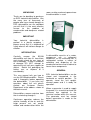
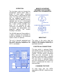
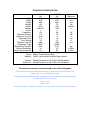
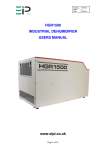
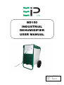
BD150
INDUSTRIAL
DEHUMIDIFIER
USER MANUAL
Drawing : - TPC337
Issue : - 2
Date : - 24/01/12
UNPACKING
room, or other enclosed space where
the dehumidifier is used.
Thank you for deciding to purchase
an EIPL Industrial dehumidifier. Like
the many tens of thousands of
people who have already bought an
EIPL dehumidifier we are confident
you will find it is the most effective
answer
to
the
problem
of
condensation and dampness related
problems.
IMPORTANT
Your industrial dehumidifier is
packed in a plastic wrapping –
please ensure that it is disposed of
safely where it will not be a danger to
children.
INTRODUCTION
Carefully
remove
the
BD150
dehumidifier unit from it’s transit box
and visually check for any signs of
transit damage. If there is evidence
of damage DO NOT attempt to
operate the unit, call your supplier for
advice. Retain the packaging for
further use, or dispose of it
considerably.
This user manual tells you how to
use the BD150 dehumidifier. Please
read it thoroughly before operating
the dehumidifier. If you have any
questions about the unit please
contact our Customer Service
Department at the address shown at
the back manual.
Dehumidifiers remove moisture from
the air circulating through it.
Continuous operation reduces the
relative humidity of the air and this
helps prevent rust, rot, mould,
mildew and condensation within the
A dehumidifier consists of a motor,
compressor unit, a refrigerant
condenser, an air circulating fan, a
refrigerated surface, a means of
collecting and disposing of the
condensed moisture and a cabinet to
house these components.
GENERAL
EIPL Industrial dehumidifiers can be
stored and transported in the
horizontal or vertical position. To
operate, stand the unit upright,
connect power and it is ready for
operation.
When a generator is used to supply
the power, it is essential to check the
minimum kva required in the
technical section within this manual.
The generator must be started
before connection is made to the
dehumidifier.
OPERATION
The fan draws moist air through the
refrigerated surface which cools it
below it’s dew point, removing
moisture which is collected and lead
away. The cool air then passes over
the hot condenser, where it is
reheated. With the addition of other
radiated heat the air is discharged
into the room at a higher temperature
but a lower relative humidity than
when the air entered the unit.
Continuous circulation of the room
air through the dehumidifier unit
gradually reduces the relative
humidity in the room.
MAINS PLUG WIRING
INFORMATION FOR EBAC
INDUSTRIAL DEHUMIDIFERS
The BD150 Industrial Dehumidifier is
a robust, compact unit designed to
control the humidity in the enclosed
space in which it is placed.
IMPORTANT
The unit is thermally protected and
will switch off for a period if the
maximum operating temperature of
35°C is exceeded.
The wires in the mains lead are
coloured and must be connected as
shown in the diagrams above by a
qualified electrician.
ELECTRICAL CONNECTIONS
The wire which is coloured Green
and Yellow must be connected to the
terminal marked E or by the Earth
symbol. The wire which is coloured
Blue must be connected to the
terminal in the plug which is marked
with the letter N or coloured Black.
The wire which is coloured Brown
must be connected to the terminal
which is marked with the letter L or
coloured Red.
CHANGING THE FUSE
13 amp fuses that are ASTA
approved to BS1362 should only be
used.
BASIC STEPS FOR DRYING
Ensure that all EXTERNAL doors
and windows are CLOSED. Where
no doors or windows are fitted,
temporarily screen off the openings.
POSITIONING
For small areas position centrally in
the area to be dried. For larger
areas such as open plan buildings,
offices, factories, a number of dryers
may be required, in such cases they
should be spread evenly around the
area.
Ensure that no unit is
positioned in such a way that it blows
directly into another.
For private house or flats, position
the dryer on one floor at a time,
starting at the lowest floor, closing all
internal doors on the floor previously
dried. Continue until all floor levels
have been dried.
Note when a particular damp patch is
to be dried out that the air outlet grille
should be directed towards that area
but should NEVER be closer than
1m to the surface. At no time should
the inlet grilles be covered or
obstructed.
PORTABLE CONTAINERS
Position a closed top container
underneath the water discharge pipe
(approximately 25 litre capacity).
Place a short length of pipe one end
over the discharge pipe and the
other end in the container. Use a
transparent container, this will enable
you to check the level of the water
and so prevent overflowing. As the
unit will be running for long periods
of time, e regular check should be
made on the container water level.
PERMANENT DRAINAGE
Connect a flexible hose to the water
discharge pipe of sufficient length so
that it will reach a permanent drain.
The gravity head created will allow
for a gradual fall from the unit to the
drain. Ensure that the hose is free of
kinks and is not allowed to rise at
any point above the level of the
discharge
point
from
the
dehumidifier. Any air locks which
may be created, should the level be
raised by the hose passing over
obstructions, could cause the water
to “back up” the hose and spill form
the dryer.
DRAINAGE
Under most operating conditions
water will be produced continuously
and it is important that it is drained
away correctly and not allowed to
spill. Any spillage will evaporate and
will, therefore, have to be recycled
through the dryer again, which in
effect, only prolongs the drying
period.
SWITCHING ON
Plug the unit into the power supply
and switch on.
Turn the rotary
switch to the ON position. (On dual
voltage units turn the rotary switch to
the correct power supply voltage).
Where applicable press and hold the
push button for 1 second. The unit
should now start.
SWITCHING OFF
Turn the rotary switch to the OFF
position. Turn off the power supply
and disconnect.
SPECIAL FEATURES
DEFROST OPERATION
If the ambient temperature of the
room in which the dehumidifier is
conditioning, falls below 15°C ice will
form on the evaporator coil as air
passes over it. Over a period of time
this build up of ice will effect the
efficiency of the dehumidifier on it’s
ability to maintain the required set
conditions within the room.
The BD150 is therefore fitted with a
defrost control device. This defrost
control device is timed to operate
every 42 minutes for a period of 4
minutes.
During the defrost cycle the high
pressure
hot
gas
from
the
compressor is diverted into the
evaporator coil where it melts the ice
which has formed on the evaporator
coil.
DUAL VOLTAGE MODELS
The BD150 dehumidifier unit is fitted
with a transformer which will allow
the unit to operate on either 110volts
or 230volts 1ph 50Hz power supply.
All electrical components within the
dehumidifier are rated for 110volts,
for safety reasons. The rotary switch
allows for the selection of the
required voltage prior to starting the
unit.
VOLTAGE PROTECTION
DEVICE
The dual voltageBD150 dehumidifier
unit is fitted as standard with a
unique voltage selection protection
device.
Should the unit be connected to
110volts supply and the rotary
selector switch set inadvertently to
230volts , the unit will not start.
This unit is fitted with a screw type in
line fuse holder with a 10 amp anti
fuse holder.
SAFETY
•
•
•
•
•
•
•
•
•
•
•
•
DO NOT USE THE UNIT IF THE
CABINET OR POWER CORD IS
DAMAGED.
DO NOT INSERT OBJECTS
INTO ANY OF THE GRILLES ON
THE MACHINE.
DO
NOT
COVER
OR
OBSTRUCT AIRFLOW FROM
THE GRILLES
DO NOT OPERATE THE UNIT
WITH THE COVERS REMOVED.
DO
NOT
ATTEMPT
ANY
REPAIRS SHOULD THE UNIT
FAIL TO OPERATE.
DO NOT STAND ON THE UNIT.
DO NOT ATTEMPT TO LIFT
HEAVY UNITS UN ASSISTED.
DO CHECK THE PLUG ON THE
EQUIPMENT MATCHES THE
SUPPLY
DO USE THIS UNIT ONLY FOR
THE PURPOSE FOR WHICH IT
WAS DESIGNED.
DO ENSURE THE POWER
CORD
AND
SUPPLY
IS
EARTHED CORRECTLY.
DO CHECK THE VOLTAGE
SELECTION
BEFORE
ATTAMPTING TO POWER UP
THE UNIT (DUAL VOLTAGE
UNITS ONLY).
DO
USE
A
RESIDUAL
CURRENT
DEVICE
“RCD”
WHERE POSSIBLE.
SERVICE
This machine should be serviced
by qualified Ebac personnel or
others
having
technical
competence
in
servicing
refrigeration equipment following
the instructions in the Ebac
Service Manual.
SPARES
Full spare parts listings and Ebac
Service Manuals are available
upon request by contacting Ebac
Industrial Products Ltd as listed
on the back of this manual.
OZONE FRIENDLY
The gas which is used inside the
hermitically sealed refrigeration
circuit is R407c, which is an HFC.
Under NO circumstances should
this gas be released into the
atmosphere. The unit should be
serviced by trained personnel
who will re-claim the removed
gas.
DISPOSAL OF THE UNIT
At the end of the machines
working life the refrigerant must
be disposed of in the correct
manner.
CONTACTING EIPL CUSTOMER SERVICES
If you have any further queries please contact the EIPL customer Services
Department on 01388 664400 and have the following information to hand:
• Part Number and Serial Number of the machine(located on the
rating plate at the front of the machine)
• Full name and address
• Where your machine was purchased
TECHNICAL SPECIFICATION
Height:
Width:
Depth:
Weight:
Airflow:
Voltage:
Phase:
Frequency:
Maximum Power:
Maximum Current:
Generator Size:
Fuse Rating:
Effective Volume:
Refrigerant Type:
Refrigerant Quantity:
Normal Extraction:
Maximum Extraction:
Noise Level:
Finish:
Mobility:
1021800
1021900
UK
UK
915
915
610
610
692
692
80
75
510
510
230/110
230
1
1
50
50
1.5
1.5
8/16
8
1.5
1.5
13
13
300
300
R407c
R407c
0.54
0.54
18
18
82
82
Less than 70dba when running
Epoxy Coated Zintec Steel
Light in construction and easily positioned
Units of
Measure
mm
mm
mm
Kg
m3/min
V
Hz
kW
A
kva
A
m3
Kg
L/24hrs
L/24hrs
Normal: Rated Extraction at 15°C 65% RH Conditions
Maximum: Rated Extraction at 45°C 99% RH Conditions
This machine has been manufactured in the United Kingdom
"This product contains fluorinated greenhouse gases covered by the Kyoto Protocol. The
refrigeration system is hermetically sealed.
The Global Warming Potential (GWP) of refrigerants used in products manufactured by Ebac
Industrial Products Ltd is as follows
R134a – 1300
R407c – 1610
For type and weight of refrigerant contained in this unit, please refer to the product data label"
UK Head Office
American Sales Office
German Sales Office
Ebac Industrial Products Ltd
St Helens Trading Estate
Bishop Auckland
County Durham
DL14 9AD
Ebac Industrial Products Inc
700 Thimble Shoals Blvd.
Suite 109, Newport News
Virginia, 23606-2575
USA
Ebac Industrial Products Ltd
Miraustra 64 – 66
13509
Berlin
Germany
Tel: +44 (0) 1388 664400
Fax: +44 (0) 1388 662590
Tel: +01 757 873 6800
Fax: +01 757 873 3632
Tel: +49 3043 557241
Fax: +49 3043 557240
www.eipl.co.uk
[email protected]
www.ebacusa.com
[email protected]
www.eip-ltd.de
[email protected]