1
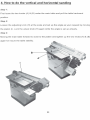
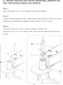
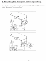
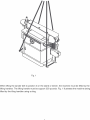
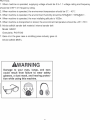
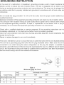
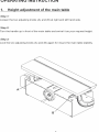
USER MANUAL
Oscillating edge belt sander
Read and take care of the operation manual and the safety instructions!
Technical changes as well as literal and sentence mistakes reserved!
KOS 2740
Ausgabe: 2011 – Revision
2. How to change the sanding belt
Open the platen cover (C) by loosing the two bolts on the top of the platen
cover. Rise up the handle bar (0) for releasing the sanding belt (E). Next, take
off the sanding belt and change a new one then put it back by pushing back the
handle bar (0) for tighten up the sanding belt.
c-----\--
9
3. When the sanding belt is not running at
the central position of the platen. How to do
the micron adjustment for sanding belt
alignment adjustment?
5tep 1:
Loosen nut (F)
5tep 2:
Rotate nut (G) clockwise or counter clockwise to adjust belt tracking.
Step 3:
When belt is tracking properly. Retighten nut (F) again.
G
10
4. How to do the vertical and horizontal sanding
Step 1:
First loose the two knobs (A) & (8) under the main table and pul! the table backward
position.
Step 2:
Loosen the adjusting knob (H) at the scale and set up the angle as your request by moving
the platen (I). Lock the adjust knob (H) again while the angle is set up already.
Step 3:
Moving the main table forward to close to the platen and tighten up the two knobs (A) & (8)
again for insure the table stability.
8----"4.l
11
5. When doing the curve sandin9L.Please do
the following steps as below:
Step 1:
Open the platen cover (J), and fasten it at the c1amp position.
Step 2:
Loosen the three socket screws. Take the idler roller cover (K) off and mount the
sanding drum spindie (L) by tighten 3 pieces of M5 x 15L soc. screw.
Step 3:
Insert the rubber drum (M) by using one piece of washer and
one piece of 1/4" x 1/2" hex. head. screw. Then you can start to do the curving
sander.
J
M----+.. . .
L
K
12
6. Mounting the dust port before operating.;.
Mounting the dust port by using tour pieces ot 1/4" x 1/4" round head screw
tightly. Please see below instruction.
13
CONNECTION MACHINE TO POWER SOURCE
POWER CONNECTION
Aseparate electrical circuit should be used for your tools. This circuit should not be less than and
should be protected with a 10 amp, time lag fuse. Have a certified electrician repair or replace
damaged or worn cord immediately. Before connecting the motor to the power line. make certain
the switch is in the "OFF" position and be sure that the electric current is of the same
characteristics as stamped on the motor nameplate. All line connections should make good
contact. Running on low voltage will damaged the motor.
WARNING : 00 NOT EXPOSE THE DUST COLLECTOR TO RAIN OR OPERATE THE
MACHINE IN DAMP LOCATIONS.
GROUNDING INSTRUCTIONS
WARNING : THIS TOOl MUST BE GROUNDED WHllE IN USE TO PROTECT THE
OPERATROR FROM ELECTRIC SHOCK.
This belt sander must be grounded. If it should malfunction or break down, grounding provides a
path of least resistance for electric current to reduce the risk of electric shock. This belt sander is
equipped with a cord having an equipment-grounding conductor and grounding plug. The plug
must be inserted into an appropriate outlet that is properly installed and grounded in accordance
with alilocal codes and ordinances.
WARN ING : Improper connection ofthe equipment-grounding conductor can result in a risk
of electric shock. Check with a qualified electrician or service person if you are in doubt as to
whether the outlet is properly grounded.
00 not modify the plug provided with the belt sander. If it will not fit the outlet, have a proper outlet
installer by a qualified electrician.
14
TROUBLE SHOOTING
~
Turn switch ·OFF" and always remove plug trom power source betore trouble shooting.
PROBLEM
Motor will not run.
PROBABLE CAUSE
REMEDY
1. Detective or broken ·ON-OFF"
switch.
2. Detective or damaged switch
cord.
3. Defective or damaged switch
relay.
1-3. Replace all broken or defective
parts before using sander.
4. Burned out motor.
4. Consult your local Authorized
Service Station. Any attempt to
repair this motor may create a
hazard unless repair is done by
a qualified technician.
5. Blown hause tuse.
Machine slows down while
sanding.
Sanding belt runs off pulleys.
Wood bums while sanding.
1. Operator applying too much
pressure to workpiece.
1. Use less press ure in applying
workpiece to sanding surface.
1. Not tracking properly.
1. Adjust tracking. See "Replacing
the Sanding Belt, Tensioning and
Tracking,
1. Sanding disc or belt glazed with
sap.
2. Excessive pressure being
applied to workpiece.
1. Replace belt or disco
2. Aeduce pressure applied to
workpiece.
ORDERING REPLACEMENT PARTS
Replacement parts may be ordered fram your local distributor. When ordering replacement parts,
always pravide the following information:
1.
2.
3.
4.
The model number and serial number ofthe belt sander.
The part number.
The part name.
The desired quantity ofthe part.
15
TABLE OF CONTENTS
ADDITONAL SAFETY RULES FOR OSCILLATING EDGE SPINDLEL
RUM SAN 0 ER -----------------------------------------------------------------------2-3
o
G R 0 UNDIN GIN STRUCTI 0 N -----------------------------------------------------4
o PERATINGIN STRUCTI 0 N ------------------------------------------------------5-9
\AJARNING ------------------------------------------------------------------------------10
TR 0 UBLE SH 00 TI NG -------------------------------------------------------------11-1 2
EXPLODED DIAGRAM AND PART LIST --------------------------------------13-20
1
IMPORTANT SAFETY RULES
Woodworking can be dangerous if safe and proper operating procedures are not followed. As with all machinery,
there are certain hazards involved with the operation of the product. Using the machine with respect and caution will
considerably lessen the possibility of personal injury. However, if normal safety precautions are overlooked or ignored,
personal injury to the operator may result.
Safety equipment such as guards, push sticks, hold-downs, feather boards, goggles, dust masks and hearing
protection can reduce your potential for injury. But even the best guard won't make up for poor judgment,
carelessness or inattention. Always use common sense and exercise caution in the workshop. If a procedure feels
dangerous, don't try it: Figure out an alternative procedure that feels safer. REMEMBER: Your personal safety is
your responsibility.
WARNING : FAllURE TO FOllOW THESE RUlES
MAY RESUlT IN SERIOUS PERSONAL INJURY
1. FOR YOUR OWN SAFETY, READ INSTRUTION
MANUAL BEFORE OPERATING THE TOOL. Learn the
tool's application and limitations as weil as the specific
hazards peculiar to it .
2. KEEP GUARDS IN PlACE and in working order.
3. AlWAYS WEAR EYE PROTECTION.
4. USE PROPER EXTENSION CORD. Make sure your
extension cord is in good condition. When using an
extension cord, be sure to use one heavy enough to
carry the current your product will draw. An undersize
cord will cause a drop in line voltage resulting in loss of
power and overheating. Refer to Table 1
5. REMOVE ADJUSTING KEYS AND WRENCHES.
Form habit of checking to see that keys and adjusting
wrenches are removed from tool before turning it "ON".
6. KEEP WORK AREA CLEAN . Cluttered areas and
benches invite accidents.
7. DON'T USE IN DANGEROUS ENVIRONMENT. Don't
use power tools in damp or wet locations, or expose
them to rain. Keep work area well-lighted.
8. KEEP CHllDREN AND VISITORS AWAY. All children
and visitors should be kept a safe distance from work
area.
9. MAKE WORKSHOP CHllDPROOF- with padlocks,
master switches, or by removing starter keys.
1O.DON'T FORCE TOOL. Don't force tool or attachment
to do a job for which it was not designed.
11.USE RIGHT TOOL. Don't force tool or attachment to
do a job for which it was not designed.
12.WEAR PROPER APPAREL. No loose clothing,
gloves, neckties, rings, bracelets, or other jewelry to get
caught in moving parts. Nonslip footwear is recommended. Wear protective hair covering to contain long hair.
13.AlWAYS USE SAFETY GLASSES. Wear safety
glasses. Everyday eyeglasses only have impact resistant
lenses; they are not safety glasses. Also use face or dust
mask if cutting operation is dusty.
14.SECURE WORK. Use clamps or a vise to hold work
when practical. It's safer than using your hand and frees
both hands to operate tool.
15.DON'T OVERREACH. Keep proper footing and
balance at all times.
2
16.MAINTAIN TOOlS IN TOP CONDITION. Keep
tools sharp and clean for best and safest performance. Follow instructions for lubricating and
changing accessories.
17.DISCONNECT TOOlS before servicing and when
changing accessories such as blades, bits, cutters,
etc.
18.USE RECOMMENDED ACCESSORIES. The use
of accessories and attachments no recommended by
use may cause hazards or risk of injury to persons.
19.REDUCE THE RISK OF UNINTENTIONAl
STARTING. Make sure switch is in "OFF" position
before plugging in power cord.
20.NEVER STAND ON TOOL. Serious injury could
occur if the tool is tipped or if the cutting tool is
accidentally contacted.
21.CHECK DAMAGED PARTS. Before further use of
the tool, a guard or other part that is damaged should
be carefully checked to ensure that it will operate
properly and perform its intended function check for
alignment of moving parts, binding of moving parts,
breakage of parts, mounting, and any other conditions
that is damaged should be properly repaired or
replaced.
22.DIRECTION OF FEED. Feed work into ablade or
cutter against the direction of rotation of the blade or
cutter only.
23.NEVER lEAVE TOOl RUNNING UNATTENDED.
TURN POWER OFF. Don't leave tool until it comes to
a complete stop.
24.DRUGS, AlCOHOl, MEDICATION. 00 not
operate tool while under the influence of drugs,
alcohol or any medication.
25.MAKE SURE TOOl IS DISCONNECTED FROM
POWER SUPPlY while motor is being mounted,
connected or reconnected.
26.WARNING:The dust generated by certain woods
and wood products can be injurious to your health.
Always operate machinery in weil ventilated areas and
provide for proper dust removal . Use wood dust
collection systems whenever possible.
ADDITIONAL SAFETY RULES FOR
Oscillating Edge Seit SpindleiDrum Sander
1. WARNING. Do not operate your machine until it is
completely assembled and installed according to the
instructions.
15. ALWAYS maintain 1/16" maximum clearance
between the table or backstop and the sanding belt or
disco
2. IF YOU ARE NOT thoroughly familiar with the
operation of Abrasive Finishing Machines, obtain
advice from your supervisor, instructor or other
qualified person.
16. NEVER wear gloves or hold the work with a rag
when sanding.
3. CAUTION: This machine is designed to sand wood
or wood-like products only. Sanding or grinding other
materials could result in fire, injury or damage to
producl.
18. 00 NOT sand pieces of material that are too
small to be safely supported.
17. SAND with the grain ofthe wood.
19. AVOID awkward hand positions where a sudden slip
could eause a hand to move into the sanding bell or disco
4. ALWAYS wear eye protection.
20. WHEN sanding a large workpiece,provide additional
support at table heighl.
5. THIS MACHINE is intended for indoor use only.
6. IMPORTANT: Mount and use this machine on
horizontal surfaces only. Use when mounted on nonhorizontal surfaces might result in motor damage.
21. 00 NOT sand with the workpiece unsupported.
Support the workpiece with the miter gage,backstop or
worktable. The only exception is curved work performed
on the outer sanding drum.
7. IF THERE 15 ANY TENDENCY for the machine to
tip over or move during certain operations such as
when sanding long or heavy boards, the machine
must be securely fastened to a supporting surface.
22. ALWAYS remove scrap pieces and other objects
from the table, backstop or belt before tuming the
machine "ON".
23. NEVER perform layout, assembly or setup work on
the table while the sander is operating.
8. MAKE SURE sanding belt runs in the proper
direction. See directional arrow on back side of bell.
24. ALWAYS turn the machine "OFF" and disconnect
the cord from the power source before installing or
removing accessories.
9. MAKE SURE the sanding belt is tracking correctly
in order that it does not run off the pulleys.
10. MAKE SURE the sanding belt is not tom or loose.
11. HOLD the work firmly when sanding.
25. NEVER leave the machine work area when the
power is "ON" or before the machine has come to a
complete stop.
12. ALWAYS use the backstop when the Belt Sander
is in the horizontal position.
26. WORKTABLE: The surface on which the workpiece
rests while performing a sanding operation.
13. ALWAYS hold the work firmlyon the table when
sanding on the disco
27. ON-OFF SWITCH PADLOCK .To safeguard the
sander from unauthorized operation and to avoid
accidental starting by children, the use of padlock is
requested. To lock out the on-off switch, open the
padlock, insert through the hole in the ON switch knob,
and close the padlock. PIace the key in loeation that is
inaccessible to children and others not qualified to use
the tool.
14. ALWAYS sand on downward side of disc when
using the disc portion of the machine, so that the work
is held securelyon the table. Sanding on the upward
side of the disc could cause the workpiece to fly up
which could be hazardous.
3
Fig.1
When lifting the sander belt to position it on the stand or beneh, the machine must be lifted by the
lifting handles. The lifting handle must be support 300 pounds. Fig. 1 illustrates the machine being
lifted by the ifting handles using a sling.
4
NOTICE:
1. When machine is operated, supplying voltage should be 0.9-1.1 voltage rating and frequency
should be 0.99-1.01 frequency rating.
2. When machine is operated, the environment temperature should be
5°C~40°C.
3. When machine is operated, the environment humidity should be 50%@40°C-90%@20°C.
4. When machine is operated, the max intallating altitude is 1000m.
5. When machine is transported or stored, the environment temperature should be -25°C-55°C.
6. Advice adhibit sander belt material: internal sander belt
Model: GXK51
Granularity: P40-P240
7. Gear oil in the gear case is middling press industry gear oil.
Advice adhibit MeiFu.
AWARNING
Damage to your eyes, lungs, and ears
could result from failure to wear safety
glasses, a dust mask, and hearing protecti on while using this machine.
5
GROUNDING INSTRUCTION
In the event of a malfunction or breakdown, grounding provides a path of least resistance for
electric current to reduce the risk of electric shock. This tool is equipped with an electric cord
having an equipment-grounding conductor and a grounding plug. The plug must be plugged into
a matching outlet that is properly installed and grounded in accordance with all local codes and
ordinances.
00 not modify the plug provided-if it will not fit the outlet, have the proper outlet installed by a
qualified electrician.
Improper connection of the equipment-grounding conductor can result in a risk of electric shock.
The conductor with insulation having an outer surface that is green with or without yellow stripes
is the equipment-grounding conductor. If repair or replacement of the electric cord or plug is
necessary, do not connect the equipment-grounding conductor to a live terminal.
Check with a qualified electrician or service personnel if the grounding instructions are not
completely understood, or if in doubt as to whether the tool is properly grounded.
Use only 3-wire extension cords that have 3-prong grounding plugs and 3-pole receptacles that
accept the tool's plug.
Repair or replace damaged or worn cord immediately.
This tool is intended for use on a circuit that has an outlet that looks like the one illustrated below
The tool has a grounding plug that looks like the plug illustrated below. Make sure the tool is
connected to an outlet having the same configuration as the plug. No adapter is available or
should be used with this tool. If the tool must be reconnected for use on a different type of electric
circuit, the reconnection should be made by qualified service personnei; and after reconnection,
the tool should comply with aillocal codes and ordinances.
GROUN~
PIN
(D)
Table 1
Minimum gage tor Cord
Volt
Ampere Rating
240V
Total length of cord in feet
50ft
100ft
More than Not more than
200ft
300ft
AWG
6
10
18
16
14
12
10
12
16
16
14
12
6
ACCESSORIES
ITEM
1
2
3
4
5
6
7
8
9
10
11
12
13
14
15
DESCRIPTION
PLATE
SCREW M8*25
SCREW M6*40
BIGWASHER
SCREW M6*15
BOLT M8*12
FENCE
PAN SCREW M6*10
FLAT WASHER 6
PACKING WASHER
HANDLE
RUBBER DRUM 38
DRUM SANDING
PAPER 38
DRUM
SANDINGPAPER 50
REBBR DRUM 50
QTY ITEM
DESCRIPTION
1
16 HANDLE
1
17 DRUM SANDING
PAPER 78
2
1
18 RUBBER DRUM 78
2
19 SAN DING DRUM
1
SPINDLE
1
20 U-TABLE
21 HANDLE
4
4
22 U-TYPE PACKING I
1
23 HANDLE 8-10
1
24 HANDLE 12-14
1
25 HANDLE 4MM
1
26 HANDLE 5MM
27 HANDLE 6MM
1
28 U-TYPE PACKING II
29 U-TYPE PACKING IV
1
30 ROD
QTY
1
1
1
1
1
1
1
1
1
1
1
1
1
1
1
~
~
..
7
20
19
7
OPERATING INSTRUCTION
1.
Height adjustme"t of the mai" table
Step 1:
Loosen the two adjusting knobs (A) and (8) at right and left hand side.
Step 2:
Turn the handle up in front of the main table and swivel it as your request height.
Step 3:
Lock the two adjusting knobs (A) and (8) again for insure the main table stability.
A
8