1
&KDQJHIRU/LIH
6HUYLFH0DQXDO
0RGHOV *3&$-.11$$
*3+$-.11$$
*3&$-.11$$&ROG3ODVPD
*3+$-.11$$&ROG3ODVPD
*3+$-.11$$'DUN%URZQ
5HIULJHUDQW5
*5(((/(&75,&$33/,$1&(6,1&2)=+8+$,
7DEOHRI&RQWHQWV
7DEHRI&RQWHQWV
6XPPDU\DQG)HDWXUHV 6DIHW\3UHFDXWLRQV 6SHFL¿FDWLRQV &RQVWUXFWLRQ9LHZV 5HIULJHUDQW6\VWHP'LDJUDP 6FKHPDWLF'LDJUDP (OHFWULFDO'DWD (OHFWULFDO:LULQJ 3ULQWHG&LUFXLW%RDUG )XQFWLRQDQG&RQWURO
2SHUDWLQJ0HWKRGV 1DPHVDQG)XQFWLRQV5HPRWH&RQWUROOHU 'HVFULSWLRQRI(DFK&RQWURO2SHUDWLRQ)XQFWLRQDQG&RQWURO ,QVWDOODWLRQ,QVWUXFWLRQV ([SORGHG9LHZVDQG3DUWV/LVW 7URXEOHVKRRWLQJ &RQ¿UPEHORZSRLQWVEHIRUHDQ\IDLOXUHVRFFXUUHG (UURU&RGH )DLOXUH5HSDLU )DLOXUH3KHQRPHQRQDQG6ROXWLRQ 5HPRYDO3URFHGXUH 6XPPDU\DQG)HDWXUHV
6XPPDU\DQG)HDWXUHV
0RGHOV
*3&$-.11$$
*3+$-.11$$
*3&$-.11$$&ROG3ODVPD
*3+$-.11$$&ROG3ODVPD
*3+$-.11$$'DUN%URZQ
5HPRWH&RQWUROOHU
FAN AUTO
OPER
AIR HEALTH X-FAN
HUMIDITY
FILTER
TURBO
HOUR
ON/OFF
ON/OFF
<%)
MODE
FAN
X-FAN
TEMP
TIMER
TURBO
SLEEP
LIGHT
6DIHW\3UHFDXWLRQV
6DIHW\3UHFDXWLRQV
Installing, starting up, and servicing air conditioner can be
All installation or repair work shall be performed by your dealer
hazardous due to system pressure, electrical components, and
or a specialized subcontractor as there is the risk of fire, electric
equipment location, etc.
shock, explosion or injury.
Only trained, qualified installers and service personnel are
allowed to install, start-up, and service this equipment.
Follow all the installation instructions to minimize the risk
Untrained personnel can perform basic maintenance functions
of damage from earthquakes, typhoons or strong winds.
such as cleaning coils. All other operations should be
performed by trained service personnel.
Avoid contact between refrigerant and fire as it generates
When handling the equipment, observe precautions in the
poisonous gas.
manual and on tags, stickers, and labels attached to the
Apply specified refrigerant only. Never have it mixed with
equipment. Follow all safety codes. Wear safety glasses and
any other refrigerant. Never have air remain in the
work gloves. Keep quenching cloth and fire extinguisher nearby
refrigerant line as it may lead to rupture and other hazards.
when brazing.
Make sure no refrigerant gas is leaking out when
Read the instructions thoroughly and follow all warnings or
installation is completed.
cautions in literature and attached to the unit. Consult local
Should there be refrigerant leakage, the density of
refrigerant in the air shall in no way exceed its limited
building codes and current editions of national as well as local
value , or it may lead to explosion
electrical codes.
.
Keep your fingers and clothing away from any moving
Recognize the following safety information:
parts.
Clear the site after installation. Make sure no foreign
Warning Incorrect handling could result in
personal injury or death.
Caution
objects are left in the unit.
Always ensure effective grounding for the unit.
Incorrect handling may result in
minor injury, or damage to product
or property.
Caution
Warning
Never install the unit in a place where a combustible gas
might leak, or it may lead to fire or explosion.
All electric work must be performed by a licensed technician
Make a proper provision against noise when the unit is
according to local regulations and the instructions given in this
installed at a telecommunication center or hospital.
manual.
Provide an electric leak breaker when it is installed in a
watery place.
Before installing, modifying, or servicing system, main
Never wash the unit with water.
electrical disconnect switch must be in the OFF position.
Handle unit transportation with care. The unit should not be
There may be more than 1 disconnect switch. Lock out and
carried by only one person if it is more than 20kg.
tag switch with a suitable warning label.
Never touch the heat exchanger fins with bare hands.
Never supply power to the unit unless all wiring and tubing
Never touch the compressor or refrigerant piping without
are completed, reconnected and checked.
wearing glove.
This system adopts highly dangerous electrical voltage.
Do not have the unit operate without air filter.
Incorrect connection or inadequate grounding can cause
Should any emergency occur, stop the unit and disconnect
personal injury or death. Stick to the wiring diagram and all
the power immediately.
the instructions when wiring.
Have the unit adequately grounded in accordance with
local electrical codes.
Have all wiring connected tightly. Loose connection may
lead to overheating and a possible fire hazard.
6SHFL¿FDWLRQV
6SHFL¿FDWLRQV
*3&$-.11$$
*3&$-.11$$&ROG3ODVPD
0RGHO
&.
&.
3URGXFW&RGH
3RZHU
6XSSO\
5DWHG9ROWDJH
5DWHG)UHTXHQF\
*3+$-.11$$
*3+$-.11$$&ROG3ODVPD
*3+$-.11$$'DUN%URZQ
&.
&.
&.
9̚
+]
3KDVHV
&RROLQJ&DSDFLW\
:
+HDWLQJ&DSDFLW\
:
&RROLQJ3RZHU,QSXW
:
+HDWLQJ3RZHU,QSXW
:
&RROLQJ3RZHU&XUUHQW
$
+HDWLQJ3RZHU&XUUHQW
$
0D[RSHUDWLRQ,QSXW
:
0D[RSHUDWLRQ&XUUHQW
$
$LU)ORZ9ROXPH+0/
P K
/K
((5
::
&23
::
6((5
::
+63)
::
7
7
'HKXPLGLI\LQJ9ROXPH
$SSOLFDWLRQ$UHD
P
&OLPDWH7\SH
,VRODWLRQ
0RLVWXUH3URWHFWLRQ
,
,
,3
,3
3HUPLVVLEOH([FHVVLYH2SHUDWLQJ
3UHVVXUHIRUWKH'LVFKDUJH6LGH
03D
3HUPLVVLEOH([FHVVLYH2SHUDWLQJ
3UHVVXUHIRUWKH6XFWLRQ6LGH
03D
&DSLOODU\
&DSLOODU\
7KURWWOLQJ0HWKRG
'HIURVWLQJ0HWKRG
)XVH
$
$XWRPDWLF'HIURVWLQJ
2SHUDWLRQ7HPS
R
&
a
a
$PELHQW7HPS&RROLQJ
R
&
a
a
$PELHQW7HPS+HDWLQJ
R
&
a
6RXQG3UHVVXUH/HYHO+0/
G%$
6RXQG3RZHU/HYHO+0/
G%$
'LPHQVLRQ:;+;'
PP
;;
;;
'LPHQVLRQRI&DUWRQ%R[/;:;+
PP
;;
;;
'LPHQVLRQRI3DFNDJH/;:;+
PP
;;
;;
1HW:HLJKW
NJ
*URVV:HLJKW
NJ
5$
5$
5HIULJHUDQW
5HIULJHUDQW&KDUJH
NJ
6SHFL¿FDWLRQV
&RPSUHVVRU0DQXIDFWXUHU7UDGHPDUN
&RPSUHVVRU0RGHO
&RPSUHVVRU2LO
&RPSUHVVRU &RPSUHVVRU7\SH
5%(3RU)9&'
5%(3RU)9&'
5RWDU\
5RWDU\
$
&RPSUHVVRU5/$
$
&RPSUHVVRU3RZHU,QSXW
:
)DQ7\SH
+3$83
+3$83
&HQWULIXJDO
&HQWULIXJDO
'LDPHWHU/HQJWK';/
PP
ĭ;
ĭ;
)DQ0RWRU6SHHG+0/
UPLQ
:
)DQ0RWRU5/$
$
)DQ0RWRU&DSDFLWRU
ȝ)
$OXPLQXP)LQFRSSHU7XEH
$OXPLQXP)LQFRSSHU7XEH
ĭ
ĭ
2XWSXWRI)DQ0RWRU
)RUP
3LSH'LDPHWHU
PP
5RZ¿Q*DS
PP
&RLO/HQJWK/;';:
PP
;;
;;
:
&HQWULIXJDO
&HQWULIXJDO
ĭ
ĭ
6ZLQJ0RWRU0RGHO
2XWSXWRI6ZLQJ0RWRU
)DQ7\SH
)DQ'LDPHWHU
PP
)RUP
&RQGHQVHU
=+8+$,/$1'$
&2035(6625&2/7'
4;$&%J$
/5$
2YHUORDG3URWHFWRU
(YDSRUDWRU
=+8+$,/$1'$
&2035(6625&2/7'
4;$&%J$
$OXPLQXP)LQFRSSHU7XEH
$OXPLQXP)LQFRSSHU7XEH
3LSH'LDPHWHU
PP
ĭ
ĭ
5RZV¿Q*DS
PP
&RLO/HQJWK/;';:
PP
)DQ0RWRU6SHHG+0/
USP
;;
;;
;;
;;
:
)DQ0RWRU5/$
$
)DQ0RWRU&DSDFLWRU
ȝ)
2XWSXWRI)DQ0RWRU
7KHDERYHGDWDLVVXEMHFWWRFKDQJHZLWKRXWQRWLFH3OHDVHUHIHUWRWKHQDPHSODWHRIWKHXQLW
&RQVWUXFWLRQ9LHZV
&RQVWUXFWLRQ9LHZV
775
442
375
temp
temp
8QLWPP
5HIULJHUDQW6\VWHP'LDJUDP
5HIULJHUDQW6\VWHP'LDJUDP
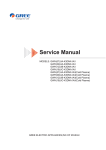
&RROLQJ2QO\0RGHO
CENTRIFUGAL FAN
CENTRIFUGAL FAN
HOT DISCHARGED AIR
COOLED AIR
COMPRESSOR
INDOOR COILS
OUTDOOR COILS
CAPILLARY
REFRIGERANT FLOW DIRECTION
&RROLQJ+HDWLQJ0RGHOV
4-Way valve
COOLED AIR
CENTRIFUGAL FAN
CENTRIFUGAL FAN
HOT AIR
HOT DISCHARGED AIR
COOLED AIR
COMPRESSOR
INDOOR COILS
OUTDOOR COILS
CAPILLARY
NOTES:
REFRIGERANT FLOW DIRECTION
COOLING MODE
HEATING MODE
6FKHPDWLF'LDJUDP
6FKHPDWLF'LDJUDP
(OHFWULFDO'DWD
PHDQLQJRIPDUNV
6\PERO
%8
%.
<(
5'
<(*1
&RORUV\PERO
%/8(
%/$&.
<(//2:
5('
<(//2:*5((1
6\PERO
%1
6\PERO
&203
&RORUV\PERO
%52:1
3DUWQDPH
&2035(6625
3527(&7,9(($57+
(OHFWULFDO:LULQJ
*3&$-.11$$
BN(BK)
WATER MOTOR
YEGN
BU
RD
AP2
RECEIVER
AP1
TUBE
ROOM
REC
L(4)
17
PCB1
PE
W1 BU
COMP.
MOTOR
K201
DISP2
DISP1
N
YEGN(GN)
N2 N2
N1
L
BU(WH)
WATER1
DISP2
DISP1
RT2
RT1
M2
~
PE
PIPE TEMP.
SENSOR
ROOM TEMP.
SENSOR
POWER
COMP(3)
C(T,U)
COMP
~
R(M,V)
S(W,X)
W5 YEGN
PE
HIGH-WP
W6
WH
NC
W7
RD
FAN
W2
W4 RD
BU YE BK WH
BK
1
2
YE
W3
C1
COM
SA
YEGN
PE
M1
~
FAN
MOTOR
RD BN
C2:5uF
6FKHPDWLF'LDJUDP
*3+$-.11$$*3+$-.11$$'DUN%URZQ
BN(BK)
YEGN
PE
BU
RD
OUTTUBE
TUBE
ROOM
WATER
N2 N2
REC
L(4)
17
PCB1
PE
W1 BU
COMP.
MOTOR
K201
DISP1
N
YEGN(GN)
N1 4V
DISP2
DISP2
DISP1
N1
L
BU(WH)
RECEIVER
AP1
RT3
RT2
RT1
M2
~
PIPE TEMP.
SENSOR
4YV
WATER MOTOR
PIPE TEMP.
SENSOR
ROOM TEMP.
SENSOR
POWER
COMP(3)
C(T,U)
COMP
~
R(M,V)
S(W,X)
W5 YEGN
PE
AP2
W6
WH
RD
FAN
HIGH-WP
W7
W2
W3
C1
W4 RD
BU YE BK WH
BK
YE
2
1
COM
NC
SA
M1
YEGN
FAN
MOTOR
~
RD BN
PE
C2:5uF
*3&$-.11$$&ROG3ODVPD
BN(BK)
ROOM TEMP.
SENSOR
WATER MOTOR
YEGN
PIPE TEMP.
SENSOR
RT1
M2
~
RT2
RD
AP2
TUBE
REC
17
K201
PCB1
DISP1
COMP(3)
PE
W1 BU
COMP.
MOTOR
C(T,U)
COMP
~
R(M,V)
S(W,X)
W5 YEGN
PE
FAN
HIGH-WP
W6
WH
NC
W7
RD
HEALTH-L
BU YE BK WH
BK
YEGN
PE
M1
~
RD BN
C2:5uF
HEALTH-N
RD
BU
COOL PLASMA
GENERATOR
COM
SA
L(4)
DISP2
DISP2
DISP1
ROOM
WATER1
N
YEGN(GN)
N2 N2
N1
L
BU(WH)
RECEIVER
AP1
PE
BU
POWER
FAN
MOTOR
W2
W4 RD
1
2
C1
YE
W3
6FKHPDWLF'LDJUDP
*3+$-.11$$&ROG3ODVPD
POWER
BN(BK)
RT1
M2
~
PE
BU
RD
AP2
PIPE TEMP.
SENSOR
RT3
RT2
17
BU(WH)
RECEIVER
AP1
N1
ROOM
WATER
OUTTUBE
TUBE
N2 N2
REC
L(4)
NC
W1 BU
COMP.
MOTOR
C(T,U)
COMP
~
R(M,V)
S(W,X)
W7
BK
HEALTH-L
BU YE BK WH
RD
BU
COOL PLASMA
GENERATOR
COM
SA
YEGN
PE
M1
~
HEALTH-N
W5 YEGN
PE
RD
FAN
N
PE
COMP(3)
HIGH-WP
W6
WH
K201
PCB1
DISP1
L
YEGN(GN)
N1 4V
DISP2
DISP2
DISP1
PIPE TEMP.
SENSOR
4YV
WATER MOTOR
YEGN
ROOM TEMP.
SENSOR
W2
W4 RD
1
2
YE
W3
C1
FAN
MOTOR
RD BN
C2:5uF
7KHVHFLUFXLWGLDJUDPVDUHVXEMHFWWRFKDQJHZLWKRXWQRWLFHSOHDVHUHIHUWRWKHRQHVXSSOLHGZLWKWKHXQLW
6FKHPDWLF'LDJUDP
3ULQWHG&LUFXLW%RDUG
Ɣ7239,(:
9
10
11
12
13 12
14
15 8
16 17 7
6
5
Ɣ%277209,(:
4
3
2
1
1DPH
:LULQJWHUPLQDORIQHXWUDOZLUH
+HDOWKOLYHZLUH
:DWHUVWULNLQJPRWRU
ZD\YDOYH
$&FXUUHQWIDQPRWRU
2XWGRRUWXEHWHPSVHQVRU
$PELHQWWHPSVHQVRU
,QGRRUWXEHWHPSVHQVRU
7HUPLQDORIGLVSOD\ERDUG
7HUPLQDORIUHPRWH
UHFHLYLQJERDUG
7HUPLQDORIZDWHUOHYHO
GHWHFWLRQ
+LJKIUHTXHQF\WUDQVIRUPHU
5HFWL¿HU
:DWHUVWULNLQJPRWRU
&RPSUHVVRUUHOD\
)XVH
+HDOWKQHXWUDOZLUH
)XQFWLRQDQG&RQWURO
)XQFWLRQDQG&RQWURO
2SHUDWLQJ0HWKRGV
4
2
Tu rb o
temp
3
1
5
6
3RZHU
3UHVVRQFHWRVWDUWDQGSUHVVRQFHPRUHWRVWRSWKHXQLW
0RGH
3UHVVWKLVEXWWRQWRFKDQJHWKHRSHUDWLRQPRGHLQRUGHURI
*3+$-.11$$&22/ĺ'5<ĺ)$1ĺ+($7
*3&$-.11$$&22/ĺ'5<ĺ)$1ĺ&22/
Ģ ġ ,Q&22/RU+($7PRGHSUHVV Ģ RQFHWKHWHPSHUDWXUHZLOOGHFUHDVH&)
3UHVV ġ RQFHWKHWHPSHUDWXUHZLOOLQFUHDVH&)7KHWHPSHUDWXUHFDQEHVHOHFWHGIURP&)a&)
)DQ
3UHVVWKLVEXWWRQWRFKDQJHWKHRSHUDWLRQIDQLQRUGHURI/2:ĺ0('ĺ785%2ĺ$872
7LPHU
3UHVVWLPHUEXWWRQWRHQWHULQWRWLPHUVHWWLQJPRGH8QGHUWKLVPRGHSUHVV Ģ RU ġ EXWWRQWRDGMXVWWKHWLPHU
VHWWLQJ7LPHUVHWWLQJZLOOLQFUHDVHRUGHFUHDVHKRXUE\SUHVVLQJ Ģ RU ġ EXWWRQZLWKLQKRXUVZKLOHWLPHU
VHWWLQJZLOOLQFUHDVHRUGHFUHDVHKRXUE\SUHVVLQJ Ģ RU ġ EXWWRQEH\RQGKRXUV$IWHUWLPHUVHWWLQJLV¿QLVKHG
WKHXQLWZLOOGLVSOD\WHPSHUDWXUHLIWKHUH¶VQRRSHUDWLRQIRUV,IWLPHUIXQFWLRQLVVWDUWHGXSWKHXSSHULQGLFDWRUZLOONHHS
WKHGLVSOD\VWDWXV2WKHUVLWZRQ¶WEHGLVSOD\HG8QGHUWLPHUPRGHSUHVVWLPHUEXWWRQDJDLQWRFDQFHOWLPHUPRGH
6OHHS
3UHVVVOHHSEXWWRQWRHQWHULQWRVOHHSPRGH,IWKHFRQWUROOHURSHUDWHVDWFRROLQJPRGHDIWHUVOHHSPRGHLVVWDUWHGXS
SUHVHWWHPSHUDWXUHZLOOLQFUHDVHE\&ZLWKLQKRXUVDQGWKHQWKHXQLWZLOORSHUDWHDWWKLVWHPSHUDWXUHDOOWKHWLPH
:KLOHLIWKHFRQWUROOHURSHUDWHVDWKHDWLQJPRGHDIWHUVOHHSPRGHLVVWDUWHGXSSUHVHWWHPSHUDWXUHZLOOGHFUHDVHE\
&ZLWKLQKRXUVDQGWKHQWKHXQLWZLOORSHUDWHVDWWKLVWHPSHUDWXUHDOOWKHWLPH6OHHSIXQFWLRQLVQRUDYDLODEOHIRUIDQ
PRGHGU\LQJPRGHDQGDXWRPRGH,IVOHHSIXQFWLRQLVVWDUWHGXSWKHXSSHULQGLFDWRUZLOONHHSWKHGLVSOD\VWDWXV
2WKHUVLWZRQ¶WEHGLVSOD\HG
&22/PRGH
7RVHOHFWDSODFHQHDUWKHGRRUDQGZLQGRZLQVWDOOWKHH[KDXVWGXFW
3UHVV02'(NH\WRVHOHFW&22/PRGH
3UHVV Ģ RU ġ NH\WRVHWWKHVXLWDEOHWHPS&) ̚ &)
+($7PRGHQRWIRURQO\FRROLQJXQLW
3UHVV³02'(´NH\WRVHOHFW³+($7´PRGH
3UHVV Ģ RU ġ NH\WRVHWWKHVXLWDEOHWHPS&) ̚ &)
'5<PRGH
3OHDVHFORVHWKHGRRUDQGZLQGRZLQRUGHUWRREWDLQWKHEHWWHUGHKXPLGLI\LQJHIIHFW
3UHVV02'(NH\VHOHFWWKH'5<PRGHWKHXQLWZLOOUXQLQWKH'5<PRGHDWWKH
VDPHWLPHWKHXSSHUPRWRULVUXQQLQJDWWKHORZVSHHGLWLVQRWDGMXVWDEOH
)$1PRGH
:KHQWKHXQLWUXQVLQ)$1PRGHLWFDQVHOHFWVSHHGV
)XQFWLRQDQG&RQWURO
1DPHVDQG)XQFWLRQV5HPRWH&RQWUROOHU
1
ON/OFF
Press it to start or stop operation.
2
MODE
Press it to select operation mode (AUTO/COOL/DRY/FAN/HEAT).
3
Press it to decrease temperature setting.
4
+
Press it to increase temperature setting.
5
2
1
3
Press it to set fan speed.
6
4
Press it to set swing angle.
7
6
5
7
FAN
Press it to turn on or off health function.
8
8
9
9
10
11
12
13
14
HEALTH SAVE
Press it to set left & right swing angle.
X-FAN(X-FAN is the alternative expression of BLOW for the purpose
of understanding.)
TEMP
11 TIMER
10
Press it to set timer ON/ timer OFF.
12
13
14
TURBO
SLEEP
LIGHT
Press it to turn on/off the light.
24
FAN
AUTO
OPER
AIR HEALTH X-FAN
HUMIDITY
15
16
17
18
15
MODE icon:
If MODE button is pressed, current operation mode icon
FILTER
23
TURBO
HOUR
ON/OFF
22
21
19
20
(AUTO),
( COOL),
(DRY),
(FAN) or
(HEAT is only for heat
pump models) will show.
16
LOCK icon:
17
LIGHT icon:
18
SLEEP icon :
19
TEMP icon:
is displayed by pressing "+" and “-” buttons simultaneously. Press them again to clear the display.
is displayed by pressing the LIGHT button. Press LIGHT button again to clear the display.
is displayed by pressing the SLEEP button. Press this button again to clear the display.
Pressing TEMP button,
circularly.
(set temperature),
(ambient temperature) ,
(outdoor ambient temperature) and blank is displayed
)XQFWLRQDQG&RQWURO
20
Up & down swing icon:
21
Left & right swing icon:
22
SET TIME display:
is displayed when pressing the up & down swing button. Press this button again to clear the display.
is displayed when pressing the left & right swing button.Press this button again to clear the display.
After pressing TIMER button, ON or OFF will blink.This area will show the set time.
23
DIGITAL display:
This area will show the set temperature. In SAVE mode,"SE" will be displayed. During defrosting operation, “H1” will be displayed.
24
FAN SPEED display:
Press FAN button to select the desired fan speed setting(AUTO-Low-Med-High).Your selection will be displayed in the LCD windows,
except the AUTO fan speed.
5HPRWHFRQWUROOHUGHVFULSWLRQ
1 ON/OFF:
Press this button to turn on the unit. Press this button again to turn off the unit.
2
MODE:
Each time you press this button,a mode is selected in a sequence that goes from AUTO, COOL,DRY, FAN, and HEAT *, as the
following:
AUTO COOL DRY FAN
HEAT*
*Note: Only for models with heating function.
After energization, AUTO mode is defaulted. In AUTO mode, the set temperature will not be displayed on the LCD, and the unit will
automatically select the suitable operation mode in accordance with the room temperature to make indoor room comfortable.
3
+:
Press this button to increase set temperature. Hold it down for above 2 seconds to rapidly increase set temperature. In AUTO mode,
set temperature is not adjustable.
4
-:
Press this button to decrease set temperature. Hold it down for above . 2 seconds to rapidly decrease set temperature. In AUTO
mode, set temperature is not adjustable.
5
FAN :
This button is used for setting fan speed in the sequence that goes from AUTO,
,
,
to then back to Auto.
AUTO
Low speed
Medium speed
High speed
:KHQVHWWLQJ+,*+IDQVSHHGXQLW
ZLOOGLVSOD\785%2IDQVSHHG
6
●Press
button to start or stop up & down swing function.The remote controller defaults to simple swing condition.
●Press + button and
button at the same time at unit OFF to switch between simple swing and static swing;
blinks for 2
seconds.
●In static swing condition, pressing
button, the swing angle of up & down louver changes as below:
OFF
●If the unit is turned off during swing operation,the louver will stop at present position.
7
HEALTH SAVE: Ć7KLVIXQFWLRQLVQRWDYDLODEOHIRUXQLW
Press HEALTH part of this button to turn on or off HEALTH function.Pressing SAVE part of this button,
is displayed and the unit
goes into SAVE operation mode. Press SAVE part of the button again to cancel SAVE function. During SAVE operation, the temperature and fan speed is not adjustable.
8
●Press
button to start or stop left & right swing function.The remote controller defaults to simple swing condition.
●Press + button and
button at the same time at unit OFF to switch between simple swing and static swing;
blinks for 2
seconds.
)XQFWLRQDQG&RQWURO
●In static swing condition, pressing
button, the swing angle of left & right louver changes as below:
OFF
●If the unit is turned off during swing operation,the louver will stop at present position.
9
X-FAN:
Pressing X -FAN button in COOL or DRY mode,the icon "X-FAN" is displayed and the indoor fan will continue operation for 10
minutes in order to dry the indoor unit even though you have turned off the unit. After energization, X-FAN OFF is defaulted. X-FAN
is not available in AUTO, FAN and HEAT mode.
10
TEMP:
Press this button, could select displaying the indoor setting temperature or indoor ambient temperature.When the indoor unit firstly
power on it will display the setting temperature, if the temperature's displaying status is changed from other status to"
",displays
the ambient temperature, 5s later or within 5s, it receives other remote control signal that will return to display the setting temperature. if the users haven't set up the temperature displaying status,that will display the setting temperature.
11
TIMER:
Press TIMER button at unit ON to set TIMER OFF; HOUR OFF blinks. Press TIMER button at unit OFF to set TIMER ON; HOUR
ON blinks. In this case, pressing + or - button changes time setting. Holding down either button rapidly changes time setting (time
setting range 0.5-24hours). Press TIMER button again to confirm setting; HOUR ON/OFF stops blinking. If there is not any operation
of button within 5 seconds during HOUR ON/OFF blinking, TIMER setting will be cancelled.
12
TURBO:
Press this button to activate / deactivate the Turbo function which enables the unit to reach the preset temperature in shortest time.
In COOL mode, the unit will blow strong cooling air at super high fan speed. In HEAT mode, the unit will blow strong heating air
at super high fan speed.
13
SLEEP :
Press this button to go into the SLEEP operation mode. Press it again to cancel this function. This function is available in COOL ,
HEAT (Only for models with heating function) or DRY mode to maintain the most comfortable temperature for you.
14
LIGHT:
Press LIGHT button to turn on the display's light and press this button again to turn off the display's light. If the light is turned on ,
is displayed. If the light is tunrned off,
disappears.
15 Combination of "+" and "-" buttons: About lock
Press "+ " and " " buttons simultaneously to lock or unlock the keypad. If the remote controller is locked,
case, pressing any button,
is displayed. In this
blinks three times.
16 Combination of "MODE" and "-" buttons:About switch between Fahrenheit and Centigrade.At unit OFF, press "MODE" and "- "
buttons simultaneously to switch between ℃ and ̧ .
&KDQJLQJEDWWHULHVDQGQRWLFHV
1.Remove the battery cover plate from the rear of the remote controller.
(As shown in the figure)
2.Take out the old batteries.
3.Insert two new AAA1.5V dry batteries, and pay attention to the polarity.
4. Reinstall the battery cover plate.
★Notes:
●When replacing the batteries, do not use old or different batteries,
otherwise, it may cause malfunction.
●If the wireless remote controller will not be used for a long time, please
remove batteries to prevent damage from leaking batteries.
●The operation should be performed in its receiving range.
●It should be kept 1m away from the TV set or stereo sound sets.
●If the wireless remote controller does not operate normally, please take
the batteries out and reinsert them after 30 seconds. If it still can't operate
properly, replace the batteries.
Sketch map for
replacing batteries
)XQFWLRQDQG&RQWURO
'HVFULSWLRQRI(DFK&RQWURO2SHUDWLRQ)XQFWLRQDQG&RQWURO
&RROLQJPRGH
:KHQ7DPE7SUHVHW&)WKHXQLWRSHUDWHVLQFRROLQJPRGH0HDQZKLOHFRPSUHVVRU
GUDZZDWHUPRWRUVWDUWRSHUDWLRQ,QGRRUIDQRSHUDWHVDWVHWIDQVSHHG
:KHQ7DPE7SUHVHW&)FRPSUHVVRUDQGGUDZZDWHUPRWRUVWRSRSHUDWLRQZKLOHLQGRRUIDQRSHUDWHVDWVHWIDQVSHHG
7SUHVHW&)7DPE7SUHVHW&)WKHXQLWNHHSVRULJLQDORSHUDWLRQVWDWXV
8QGHUWKLVPRGHZD\YDOYHLVGHHQHUJL]HG7KHWHPSHUDWXUHVHWWLQJUDQJHLV&)
'U\PRGH
8QGHUWKLVPRGHVHWWHPSHUDWXUHDQGDPELHQWWHPSHUDWXUHZRQ¶WEHGLVSOD\HG,QGRRUIDQRSHUDWHVDWORZIDQVSHHG
&)7DPE&)&RPSUHVVRUDQGGUDZZDWHUPRWRURSHUDWHVFRQWLQXRXVO\
+HDWLQJPRGH
:KHQ7DPE7SUHVHW&)WKHXQLWRSHUDWHVLQKHDWLQJPRGH0HDQZKLOHZD\YDOYH
FRPSUHVVRURSHUDWHVDQGLQGRRUIDQRSHUDWHVDWFROGDLUSUHYHQWLRQFRQGLWLRQ
:KHQ7SUHVHW&)7DPE7SUHVHW&)WKHXQLWNHHSVRULJLQDORSHUDWLRQVWDWXV
:KHQ7DPE7SUHVHW&)FRPSUHVVRUVWRSRSHUDWLRQVLPXOWDQHRXVO\ZD\YDOYHVWRSRSHUDWLRQDIWHU
WKHFRPSUHVVRUKDVVWRSSHGIRUPLQXWHV,QGRRUIDQRSHUDWHVDWEORZLQJUHVLGXDOKHDWFRQGLWLRQHU
8QGHUWKLVPRGHWKHWHPSHUDWXUHVHWWLQJUDQJHLV&)
)DQPRGH
8QGHUWKLVPRGHVHWWHPSHUDWXUHDQGDPELHQWWHPSHUDWXUHZRQ¶WEHGLVSOD\HG,QGRRUIDQRSHUDWHVDWVHWIDQVSHHG
$XWRPRGH
8QGHUDXWRPRGHVWDQGDUGFRROLQJ7SUHVHW &)VWDQGDUGKHDWLQJ7SUHVHW &)
+HDWSXPSXQLW
7DPE!&)WKHXQLWWXUQVLQWRDXWRFRROLQJPRGH7DPE&)WKHXQLWWXUQVLQWRKHDWLQJPRGH
&)7DPE&)LIWKHXQLWRSHUDWHVDWKHDWLQJPRGHSUHYLRXVO\WKHXQLWNHHSVKHDWLQJRSHUDWLRQVWDWXV,IWKHXQLWGLGQ¶W
RSHUDWHDWKHDWLQJPRGHSUHYLRXVO\WKHXQLWZLOOWXUQWRGU\PRGH&)7DPE&)WKHXQLWWXUQVLQWRDXWRGU\PRGH
)RUWKH¿UVWHQHUJL]DWLRQ&)7DPE&)WKHXQLWWXUQVLQWRGU\LQJRSHUDWLRQPRGH
2WKHUIXQFWLRQ
7LPHU
*HQHUDO7LPHU
7LPHU21FDQEHVHWDWXQLW2)),IVHOHFWHG21WLPHLVUHDFKHGWKHXQLWZLOOVWDUWWRRSHUDWHDFFRUGLQJWRSUHYLRXVVHWWLQJVWDWXV
7LPHVHWWLQJUDQJHLVKULQPLQXWHLQFUHPHQWV
7LPHU2))FDQEHVHWDWXQLW21,IVHOHFWHG2))WLPHLVUHDFKHGWKHXQLWZLOOVWRSRSHUDWLRQ7LPHVHWWLQJUDQJHLVKULQ
PLQXWHLQFUHPHQWV
&ORFN7LPHU
7LPHU21
,IWLPHU21LVVHWGXULQJRSHUDWLRQRIWKHXQLWWKHXQLWZLOOFRQWLQXHWRRSHUDWH,IWLPHU21LVVHWDWXQLW
2))XSRQ21WLPHUHDFKHVWKHXQLWZLOOVWDUWWRRSHUDWHDFFRUGLQJWRSUHYLRXVVHWWLQJVWDWXV
7LPHU2))
,IWLPHU2))LVVHWDWXQLW2))WKHV\VWHPZLOONHHSVWDQGE\VWDWXV,IWLPHU2))LV
VHWDWXQLW21XSRQ2))WLPHUHDFKHVWKHXQLWZLOOVWRSRSHUDWLRQ
6OHHSIXQFWLRQ
:KHQVHWWLQJVOHHSIXQFWLRQXQGHUFRROLQJPRGH7SUHVHWZLOOLQFUHDVH&)DIWHUKRXUVKRXUV
ODWHU7SUHVHWZLOOLQFUHDVH&)DXWRPDWLFDOO\7KHXSSHUOLPLWRIWHPSHUDWXUHLV&)
:KHQVHWWLQJVOHHSIXQFWLRQXQGHUKHDWLQJPRGH7SUHVHWZLOOGHFUHDVH&)DIWHUKRXUVKRXUV
ODWHU7SUHVHWZLOOGHFUHDVH&)DXWRPDWLFDOO\7KHORZHUOLPLWRIWHPSHUDWXUHLV&)
%X]]HU
8SRQHQHUJL]DWLRQRURSHUDWLRQWKHEX]]HUZLOOJLYHRXWVRXQG
&RQWUROEXWWRQ
212))EXWWRQ
7XUQRQRUWXUQRIIXQLW
0RGHEXWWRQ
7KHPRGHZLOOEHVZLWFKHGDVEHORZVHTXHQFH
+HDWSXPSXQLWFRROLQJGU\LQJIDQKHDWLQJ
&RROLQJRQO\XQLW&RROLQJGU\LQJIDQ
7HPSHUDWXUH³³EXWWRQ
,IVHWWHPSHUDWXUHXQGHU21VWDWXVWHPSHUDWXUHZLOOGHFUHDVH&RU)DIWHUHDFKSUHVVLQJRIWKLVEXWWRQ7KHWHPSHUDWXUHFDQ¶W
EHVHWORZHUWKDQ&RU)7KHEXWWRQLVLQYDOLGXQGHUDXWRGU\LQJDQGIDQPRGH$GMXVWWLPHUWLPHLQWLPHUVHWWLQJVWDWXV
7HPSHUDWXUH³³EXWWRQ
,IVHWWHPSHUDWXUHXQGHU21VWDWXVWHPSHUDWXUHZLOOLQFUHDVH&RU)DIWHUHDFKSUHVVLQJRIWKLVEXWWRQ7KHWHPSHUDWXUHFDQ¶W
)XQFWLRQDQG&RQWURO
EHVHWKLJKHUWKDQ&RU)7KHEXWWRQLVLQYDOLGXQGHUDXWRGU\LQJDQGIDQPRGH$GMXVWWLPHUWLPHLQWLPHUVHWWLQJVWDWXV
'LVSOD\
'LVSOD\RILQGLFDWRU
:KHQWXUQLQJRIWKHXQLWWKHFXUUHQWRSHUDWLRQPRGHLQGLFDWRUZLOOEHGLVSOD\HG/('ODPSVIRU&RROLQJ+HDWLQJ'U\LQJDQG)DQ
'XDOGLVSOD\
:KHQWKHXQLWLVWXUQHGRQIRUWKH¿UVWWLPHQLH[LHWXEHLVGHIDXOWHGWRGLVSOD\VHWWHPSHUDWXUH:KHQWKH
XQLWUHFHLYHGWKHVLJQDORIVHWWHPSHUDWXUHQL[LHWXEHGLVSOD\VHWWHPSHUDWXUH:KHQWKHXQLWUHFHLYHGWKH
VLJQDORIDPELHQWWHPSHUDWXUHWKHQL[LHWXEHGLVSOD\VFXUUHQWLQGRRUDPELHQWWHPSHUDWXUH
/LJKWFRQWURO
:KHQWKHXQLWLVWXUQHGRQIRUWKH¿UVWWLPHOLJKWLVGHIDXOWHG21,IVHWWLQJOLJKW21E\UHPRWHFRQWUROOHULQGLFDWRUDQGGXDOQL[LH
WXEHGLVSOD\VFXUUHQWVHWVWDWXV,IVHWWLQJOLJKW2))E\UHPRWHFRQWUROOHUOLJKWZLOOEHWXUQHGRIILPPHGLDWHO\,IWKHUH¶VRSHUDWLRQIRU
EXWWRQRQSDQHODQGUHPRWHFRQWUROOHUZKHQVHWWLQJOLJKW2))E\UHPRWHFRQWUROOHULQGLFDWRUDQGGXDOQL[LHWXEHZLOOGLVSOD\VHW
VWDWXVIRUVDQGWKHQWXUQRIIWKHOLJKW
$XWRIDQVSHHGFRQWURO
+HDWLQJPRGH
8QGHUDXWRKHDWLQJRUQRUPDOKHDWLQJPRGHDXWRIDQVSHHGZLOORSHUDWHDVEHORZPRGH
:KHQ7DPE7SUHVHW7FRPSHQVDWLRQ&)LQGRRUIDQRSHUDWHVDWKLJKIDQVSHHG
:KHQ7SUHVHW7FRPSHQVDWLRQ&)7DPE7SUHVHW7FRPSHQVDWLRQLQGRRUIDQRSHUDWHVDWPLGGOHIDQVSHHG
:KHQ7DPE7SUHVHW7FRPSHQVDWLRQLQGRRUIDQRSHUDWHVDWORZVSHHG
&RROLQJPRGH
8QGHUDXWRFRROLQJRUQRUPDOFRROLQJPRGHDXWRIDQVSHHGZLOORSHUDWHDVEHORZPRGH
:KHQ7DPE7SUHVHW7FRPSHQVDWLRQ&)LQGRRUIDQRSHUDWHVDWKLJKIDQVSHHG
:KHQ7SUHVHW7FRPSHQVDWLRQ7DPE7SUHVHW7FRPSHQVDWLRQ&)LQGRRUIDQRSHUDWHVDWPLGGOHIDQVSHHG
:KHQ7DPE7SUHVHW7FRPSHQVDWLRQLQGRRUIDQRSHUDWHVDWORZVSHHG
$XWRIDQXQGHUIDQPRGHLVDVWKHVDPHRIFRROLQJPRGH
3RZHURIIPHPRU\IXQFWLRQ
0HPRU\FRQWHQWPRGHOLJKWVHWWHPSHUDWXUHVHWIDQVSHHGVZLQJKHDOWK:KHQSRZHUIDLOXUH
WKHXQLWZLOORSHUDWHDWSUHYLRXVRSHUDWLRQVWDWXVDXWRPDWLFDOO\DIWHUSRZHUUHFRYHUHG
;)$1FRQWUROPRGH
;)$1IXQFWLRQFDQEHVHWXQGHUFRROLQJDQGGU\PRGH;)$1IXQFWLRQLVXQDYDLODEOHXQGHUDXWRKHDWLQJDQGIDQPRGH
3URWHFWLRQIXQFWLRQ
:DWHURYHUÀRZSURWHFWLRQ
%X]]HUZLOOJLYHRXWVRXQGIRUWLPHVIRUZDUQLQJ7KHFRPSOHWHXQLWZLOOVWRSRSHUDWLRQ
(UURUFRGH+LVGLVSOD\HGDQGKHDWLQJLQGLFDWRU2))VDQGEOLQNVWLPHV
)UHH]HSUHYHQWLRQSURWHFWLRQ
8QGHUIUHH]HSUHYHQWLRQSURWHFWLRQFRPSUHVVRUDQGGUDZZDWHUPRWRUVWRSRSHUDWLRQ,QGRRUIDQRSHUDWHVDWVHWIDQVSHHG
&RPSUHVVRUSURWHFWLRQ
&RPSUHVVRUFDQEHUHVWDUWHGRQO\DIWHUPLQXWHVGHOD\HG
,QVWDOODWLRQ,QVWUXFWLRQV
,QVWDOODWLRQ,QVWUXFWLRQV
$FFHVVRULHVDQG,QVWDOODWLRQRI+HDW([KDXVW+RVW
/HQJWKUDQJHRIH[KDXVWSLSHVKRXOGEHaFP,WLVUHFRPPHQGHGWRXVHLWZLWKVKRUWHVWOHQJWK
:KHQLQVWDOOLQJH[KDXVWSLSHVKRXOGEHDVÀDWDVSRVVLEOH'RQ
WSURORQJWKHSLSHRU
FRQQHFWLWZLWKRWKHUH[KDXVWSLSHRULWZRXOGFDXVHDEQRUPDORSHUDWLRQ
100cm
&RUUHFWLQVWDOODWLRQLVDVVKRZQLQ¿JXUH:KHQLQVWDOOLQJLWRQZDOO
KHLJKWRIKDOOVKRXOGEHDERXWFPIURPÀRRU
,QVWDOODWLRQ,QVWUXFWLRQV
,IWKHSLSHDUHWREHEHQWSOHDVHLQVWDOOLWE\FRQVLGHULQJIROORZLQJGLPHQVLRQ
55cm
65cm
55cm
:URQJLQVWDOODWLRQLVVKRZQLQIROORZLQJ¿JXUH,IWKHSLSHLVEHQWWRRPXFKLWZRXOGHDVLO\FDXVHPDOIXQFWLRQ
([SORGHG9LHZVDQG3DUWV/LVW
([SORGHG9LHZVDQG3DUWV/LVW
0RGHOV*3&$-.11$$*3&$-.11$$&ROG3ODVPD
62
61
63
64
65
2
1
66
3
4
5 6
7
8
9
10
11
12
13
14
60
15
16
59
1
17
18
58
19
20
21
57
22
56
23
55
54
24
53
25
52
51
50
26
49
47
48
67
68
69
46
70
45
44
71
42
43
41
40
72
39
73
36
37
38
35
74
75
29
30
31
32
33
34
76
77
27
28
78
79
([SORGHG9LHZVDQG3DUWV/LVW
1R
'HVFULSWLRQ
3DUW&RGH
*3&$-.11$$
*3&$-.11$$&ROG3ODVPD
4W\
3URGXFW&RGH
&.
&.
7RS&RYHU$VV\
0HPEUDQH
7RS&RYHU
'LVSOD\%R[
'LVSOD\&RYHU
'LVSOD\%RDUG
)RDP%DIÀH
%DIÀH3ODWH
3URSHOOHU+RXVLQJ8SSHU
6ZLQJ/HYHU
$LU/RXYHU
5HDU*ULOO
&ROG3ODVPD*HQHUDWRU
5LJKW6LGH3ODWH
&DSDFLWRU%R[6XE$VV\
&DSDFLWRU%R[
&DSDFLWRU&%%
&DSDFLWRU&%%
*XLGH%ODGH/HYHU
*XLGH/RXYHU
*XLGH/RXYHU
5HPRWH&RQWURO'LVSOD\:LQGRZ
)URQW3DQHO
)URQW3DQHO$VV\
'LVFKDUJH7XEH6XEDVV\
,QKDODWLRQ7XEH6XEDVV\
&RPSUHVVRUDQG)LWWLQJV
*
*
&RPSUHVVRU*DVNHW
(OHFWULF%R[&RYHU
6KLHOG&RYHURI(OHFWULF%R[
(OHFWULF%R[
0DLQ%RDUG
6KLHOG&RYHURI(OHFWULF%R[
(OHFWULF%R[$VV\
6SODVK:DWHU)O\ZKHHO
)DQ0RWRU
&DVWRU
ZDWHU/HYHO6ZLWFK%DVH
:DWHU/HYHO6ZLWFK
:DWHU/HYHO6ZLWFK6XEDVV\
6XSSRUWLQJ%RDUG
6XSSRUWLQJ%RDUG
0RWRUKROGHU6KDGHG3ROH0RWRU
&KDVVLV6XEDVV\
&KDVVLV$VV\
([SORGHG9LHZVDQG3DUWV/LVW
'LYHUVLRQ&LUFOH
&HQWULIXJDO)DQ
&RQGHQVHU$VV\
&DSLOODU\6XEDVV\
7HPSHUDWXUH6HQVRU
/HIW6LGH3ODWH
5HPRWHFRQWUROOHU%R[
)LOWHU6XEDVV\
*XLGH6WULS)LOWHU
5HDU3ODWH
7KUHDG5ROOLQJ+RRN
)LOWHU6XEDVV\
(YDSRUDWRU$VV\
)RDP:DWHU7UD\
7HPSHUDWXUH6HQVRU
0RWRU+ROGHU
)DQ0RWRU
3URSHOOHU+RXVLQJ8SSHU
6XSSRUWLQJ%RDUG
6XSSRUWLQJ%RDUG
&HQWULIXJDO)DQ
5HPRWH&RQWUROOHU
3RZHU&RUG
:LQGRZ/RFNLQJ%UDFNHW
%DFN3ODWH
$GMXVWLQJSODWH
%DIÀH3ODWH
%DFN3ODWH
5HDU*ULOO
5HDU&OLSXSSHU
5HDU&OLSQHWKHU
3LSH
7LHLQ
'UDLQDJH+RVH
7KHGDWDDERYHDUHVXEMHFWWRFKDQJHZLWKRXWQRWLFH
([SORGHG9LHZVDQG3DUWV/LVW
0RGHOV*3+$-.11$$*3+$-.11$$'DUN%URZQ
*3+$-.11$$&ROG3ODVPD
63
62
64
65
66
2
1
67
3
4
5 6
7
8
9
10
11
12
13
14
61
15
16
17
60
1
18
59
19
20
21
58
22
57
23
56
55
24
54
25
53
52
51
26
50
49
68
47
48
69
70
46
71
45
44
72
42
43
41
40
73
39
74
36
37
38
35
75
31
32
33
34
76
77
78
27
28
29
30
79
80
([SORGHG9LHZVDQG3DUWV/LVW
1R
'HVFULSWLRQ
3URGXFW&RGH
7RS&RYHU$VV\
0HPEUDQH
&RSLQJ
'LVSOD\%R[
'LVSOD\&RYHU
'LVSOD\%RDUG
)RDP%DIÀH
%DIÀH3ODWH
3URSHOOHU+RXVLQJ8SSHU
6ZLQJ/HYHU
$LU/RXYHU
5HDU*ULOO
&ROG3ODVPD*HQHUDWRU
5LJKW6LGH3ODWH
&DSDFLWRU%R[6XE$VV\
&DSDFLWRU%R[
&DSDFLWRU&%%
&DSDFLWRU&%%
*XLGH%ODGH/HYHU
*XLGH/RXYHU
*XLGH/RXYHU
5HPRWH&RQWURO
'LVSOD\:LQGRZ
)URQW3DQHO
)URQW3DQHO$VV\
:D\9DOYH$VV\
0DJQHW&RLO
&RPSUHVVRUDQG)LWWLQJV
&RPSUHVVRU*DVNHW
(OHFWULF%R[&RYHU
6KLHOG&RYHURI(OHFWULF%R[
(OHFWULF%R[
0DLQ%RDUG
6KLHOG&RYHURI(OHFWULF%R[
(OHFWULF%R[$VV\
6XSSRUWLQJ%RDUG
0RWRUKROGHU6KDGHG
3ROH0RWRU
6SODVK:DWHU)O\ZKHHO
)DQ0RWRU
&KDVVLV6XEDVV\
&KDVVLV$VV\
&DVWRU
ZDWHU/HYHO6ZLWFK%DVH
:DWHU/HYHO6ZLWFK
:DWHU/HYHO6ZLWFK6XEDVV\
6XSSRUWLQJ%RDUG
'LYHUVLRQ&LUFOH
&HQWULIXJDO)DQ
&RQGHQVHU$VV\
7HPSHUDWXUH6HQVRU
&DSLOODU\6XEDVV\
7HPSHUDWXUH6HQVRU
/HIW6LGH3ODWH
5HPRWHFRQWUROOHU%R[
&.
3DUW&RGH
*3+$-.11$$&ROG
3ODVPD
&.
*3+$-.11$$'DUN
%URZQ
&.
*
*
6
*
*3+$-.11$$
4W\
([SORGHG9LHZVDQG3DUWV/LVW
)LOWHU6XEDVV\
*XLGH6WULS)LOWHU
5HDU3ODWH
7KUHDG5ROOLQJ+RRN
)LOWHU6XEDVV\
(YDSRUDWRU$VV\
)RDP:DWHU7UD\
7HPSHUDWXUH6HQVRU
0RWRU+ROGHU
)DQ0RWRU
3URSHOOHU+RXVLQJ8SSHU
6XSSRUWLQJ%RDUG
6XSSRUWLQJ%RDUG
&HQWULIXJDO)DQ
5HPRWH&RQWUROOHU
3RZHU&RUG
:LQGRZ/RFNLQJ%UDFNHW
%DFN3ODWH
$GMXVWLQJSODWH
%DIÀH3ODWH
%DFN3ODWH
5HDU*ULOO
5HDU&OLSXSSHU
5HDU&OLSQHWKHU
3LSH
7LHLQ
'UDLQDJH+RVH
7KHGDWDDERYHDUHVXEMHFWWRFKDQJHZLWKRXWQRWLFH
7URXEOHVKRRWLQJ
7URXEOHVKRRWLQJ
&RQ¿UPEHORZSRLQWVEHIRUHDQ\IDLOXUHVRFFXUUHG
&RQ¿UPSRZHUVXSSO\LV2.
&KHFNWKHSOXJRISRZHUOLQHLVQRUPDOHQHUJL]HGDQGZRUN
&RQ¿UPSRZHUYROWDJH
0DNHVXUHWKHYROWDJHLVEHWZHHQQRUPDOUDQJHLIH[FHHGWKHUDQJHWKHXQLWPD\DEQRUPDOO\UXQV$&9
(UURU&RGH
3OHDVHVHHWKHEORZIDLOXUHFRQWHQWVDQGUHSDLUPHWKRGVZKHQWKHXQLWLV
HQHUJL]HGRUWKHHUURUFRGHRFFXUUHGGXULQJWKHXQLWUXQV
'LVSOD\0HWKRGRI,QGRRU8QLW
,QGLFDWRUODPS
1R
0DOIXQFWLRQ1DPH
(UURU&RGH
'XULQJEOLQNLQJ21IRU
6DQG2))IRU6
2SHUDWLRQ &22/
/DPS
/DPS
,QGRRUDPELHQW
WHPSHUDWXUH
VHQVRULVRSHQ
VKRUWFLUFXLWHG
)
2))6
DQGEOLQNV
RQFH
,QGRRUHYDSRUDWRU
WHPSHUDWXUH
VHQVRULVRSHQ
VKRUWFLUFXLWHG
)
2))6
DQGEOLQNV
WZLFH
$&6WDWXV
3RVVLEOH&DXVHV
+($7
/DPS
7KHZLULQJWHUPLQDO
EHWZHHQLQGRRUDPELHQW
7KHXQLWZLOOVWRS
RSHUDWLRQDVLWUHDFKHV WHPSHUDWXUHVHQVRUDQG
WKHWHPSHUDWXUHSRLQW FRQWUROOHULVORRVHQHG
RUSRRUO\FRQWDFWHG
'XULQJFRROLQJDQG
7KHUH¶VVKRUWFLUFXLW
GU\LQJRSHUDWLRQ
GXHWRWULSRYHURIWKH
H[FHSWLQGRRUIDQ
RSHUDWHVRWKHUORDGV SDUWVRQFRQWUROOHU
˄VXFKDVFRPSUHVVRU ,QGRRUDPELHQW
WHPSHUDWXUHVHQVRU
RXWGRRUIDQZD\
YDOYH˅VWRSRSHUDWLRQ LVGDPDJHG3OHDVH
FKHFNLWE\UHIHUULQJWR
'XULQJKHDWLQJ
RSHUDWLRQWKHFRPSOHWHWKHUHVLVWDQFHWDEOHIRU
XQLWVWRSVRSHUDWLRQ WHPSHUDWXUHVHQVRU
0DLQERDUGLVEURNHQ
7KHZLULQJWHUPLQDO
EHWZHHQLQGRRUHYDSRUDWRU
WHPSHUDWXUHVHQVRUDQG
7KHXQLWZLOOVWRS
RSHUDWLRQDVLWUHDFKHV FRQWUROOHULVORRVHQHG
WKHWHPSHUDWXUHSRLQW RUSRRUO\FRQWDFWHG
7KHUH¶VVKRUWFLUFXLW
'XULQJFRROLQJDQG
GXHWRWKHWULSRYHURI
GU\LQJRSHUDWLRQ
WKHSDUWVRQFRQWUROOHU
H[FHSWLQGRRUIDQ
RSHUDWHVRWKHUORDGV ,QGRRUHYDSRUDWRU
VWRSRSHUDWLRQ'XULQJ WHPSHUDWXUHVHQVRU
LVGDPDJHG3OHDVH
KHDWLQJRSHUDWLRQ
FKHFNLWE\UHIHUULQJWR
WKHFRPSOHWHXQLW
WKHUHVLVWDQFHWDEOHIRU
VWRSVRSHUDWLRQ
WHPSHUDWXUHVHQVRU
0DLQERDUGLVEURNHQ
7URXEOHVKRRWLQJ
2XWGRRUFRQGHQVHU
WHPSHUDWXUH
VHQVRULVRSHQ
VKRUWFLUFXLWHG
)
2YHUFXUUHQW
SURWHFWLRQ
(
2))6
DQGEOLQNV
WLPHV
2))6
DQGEOLQNV
WLPHV
7KHZLULQJWHUPLQDO
EHWZHHQRXWGRRUFRQGHQVHU
WHPSHUDWXUHVHQVRUDQG
7KHXQLWZLOOVWRS
FRQWUROOHULVORRVHQHG
RSHUDWLRQDVLWUHDFKHV
RUSRRUO\FRQWDFWHG
WKHWHPSHUDWXUHSRLQW
7KHUH¶VVKRUWFLUFXLW
'XULQJFRROLQJDQG
GXHWRWKHWULSRYHURI
GU\LQJRSHUDWLRQ
WKHSDUWVRQFRQWUROOHU
FRPSUHVVRUVWRSVDQG
2XWGRRUFRQGHQVHU
LQGRRUIDQRSHUDWHV
WHPSHUDWXUHVHQVRU
'XULQJKHDWLQJ
LVGDPDJHG3OHDVH
RSHUDWLRQWKHFRPSOHWH
FKHFNLWE\UHIHUULQJWR
XQLWVWRSVRSHUDWLRQ
WKHUHVLVWDQFHWDEOHIRU
WHPSHUDWXUHVHQVRU
0DLQERDUGLVEURNHQ
8QVWDEOHVXSSO\YROWDJH
1RUPDOÀXFWXDWLRQVKDOO
EHZLWKLQRIWKHUDWHG
YROWDJHRQWKHQDPHSODWH
6XSSO\YROWDJHLVWRR
ORZDQGORDGLVWRRKLJK
0HDVXUHWKHFXUUHQWRI
OLYHZLUHRQPDLQERDUG
,IWKHFXUUHQWLVQ¶WKLJKHU
WKDQWKHRYHUFXUUHQW
SURWHFWLRQYDOXHSOHDVH
FKHFNWKHFRQWUROOHU
'XULQJFRROLQJDQG
7KHLQGRRUDQGRXWGRRU
GU\LQJRSHUDWLRQ
KHDWH[FKDQJHUVDUHWRR
FRPSUHVVRUDQG
GLUW\RUWKHDLULQOHWDQG
RXWGRRUIDQVWRS
DLURXWOHWDUHEORFNHG
ZKLOHLQGRRUIDQ
7KHIDQPRWRULVQRW
RSHUDWHV'XULQJ
UXQQLQJ$EQRUPDOIDQ
KHDWLQJRSHUDWLRQ
VSHHGIDQVSHHGLVWRR
DOOORDGVVWRS
ORZRUWKHIDQGRHVQ¶WUXQ
7KHFRPSUHVVRULVQRW
UXQQLQJQRUPDOO\7KHUH
LVDEQRUPDOVRXQGRLO
OHDNDJHRUWKHWHPSHUDWXUH
RIWKHVKHOOLVWRRKLJKHWF
7KHUH¶VEORFNDJHLQWKH
V\VWHP˄¿OWKEORFNDJH
LFHSOXJJUHDV\EORFNDJH
<YDOYHKDVQ¶WEHHQ
RSHQHGFRPSOHWHO\˅
2YHUEORZ
SURWHFWLRQ
+
5HIHUWRWKHLQGLFDWLRQRI
LQVWUXFWLRQWRGLVFKDUJH
WKHZDWHURIFKDVVLV
7URXEOHVKRRWLQJ
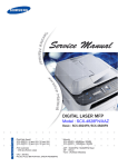
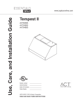
)DLOXUH5HSDLU
9.3.1 Failure for temperature sensor
Main test point:
● If the outdoor environment temperature is in normal range
● If fan motor normally runs.
● If the radiating environment of indoor and outdoor unit is good
Check the flow process of failure is:
Energize and turn on
the unit
Indoor unit display
F1-F2 ?
yes
Check the connection
status of indoor temperature sensor
no
whether it's
connected tightly?
Indoor unit displays
F3/F4/F5
no
yes
Check the connection
status of outdoor
temperature sensor
Adjust the connection
status
yes
Whether it's
connected tightly?
Replace temperature
sensor
Adjust the connection
status
yes
no
Is malfunction
eliminated?
Is malfunction
eliminated?
no
Replace temperature
sensor
no
Is malfunction
eliminated?
Replace main board
of indoor unit
no
Is malfunction
eliminated?
no
Replace main board
of outdoor unit
Energize and turn on
the unit
7URXEOHVKRRWLQJ
9.3.2 Failure for switch of water level
Main test point:
● If the defrosting tray is over-blow
● If the connection line of water level switch is good.
● If the water level switch is damaged.
Check the flow process of failure is:
Turn on the unit
Display H8
If the defrosting tray
is over-blow
Refer to the indication
of instruction to discharge
the water of chassis.
Y
N
N
ConnectionYline of
water level switch is tight.
N
Failure is
cancelled.
Y
Y
Adjust
connection
Failure is
cancelled.
Y
Replace the
switch of water
level
Failure is
cancelled.
N
Y
Y
End
Replace
control
board
7URXEOHVKRRWLQJ
9.3.3 Motor failure (including upper motor and lower motor)
Main test point:
If the motor does not rotate.
Check the flow process of failure is:
Turn on the unit
Motor does
not rotate
If the connection
line is tight.
Replace control
board
Y
N
Adjust
connection
Failure is
cancelled
Y
Failure is
cancelled
N
Replace
N
control
board
Y
Failure is
cancelled
N
Replace motor
Y
Y
End
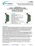
7URXEOHVKRRWLQJ
2YHUFXUUHQWSURWHFWLRQ(
Start
Is the supply voltage unstable with big fluctuation?
yes
no
Is the supply voltage too low with overload?
Normal fluctuation is within 10% of the rated voltage on the
nameplate
Malfunction is eliminated.
yes
Malfunction is eliminated.
yes
Malfunction is eliminated.
yes
no
yes
Adjust the supply voltage to maintain it within normal range
no
no
Is the indoor / outdoor heat exchanger too dirty,
or are the air inlet and outlet blocked?
yes
no
no
Is the fan motor running abnormally; is the fan speed too
low or does it fail to run?
yes
no
Measure the current of live wire
on the main board with a clamp ampere meter. Is the
current higher than the value of the overcurrent
protection?
Clean the indoor and outdoor heat exchangers and remove
the blockage of air inlet and outlet
Check the motor and reinstall the motor to have the fan run
normally
Malfunction is eliminated.
yes
Malfunction is eliminated.
yes
no
no
Replace the controller
yes
no
Is there blockage inside the system?
(Filth blockage, ice plug, greasy blockage, the Y-valve hasn’ t
been opened completely)
yes
Flush the heat exchangers with high pressure nitrogen
Malfunction is eliminated.
yes
no
no
Is the compressor running
abnormally? Is there abnormal sound or oil leakage; is
the temperature of the shell too high, etc.?
yes
Replace the compressor
no
no
Replace the control
panel
End
Malfunction is eliminated.
yes
7URXEOHVKRRWLQJ
)DLOXUH3KHQRPHQRQDQG6ROXWLRQ
Phenomenon
There is no action
after the unit is
energized.
The unit
does not
start-up
Solution
Possible results
No power supply
Check the power circuit
The power plug is not well insert or
bad connection.
Check the plug is well insert, and make sure
the connection is good.
The fuse is damaged.
Replace the fuse
The connection line of indoor unit is
loose.
Re-insert it refer to the circuit diagram.
Controller (power circuit, slug, crystal
vibration) is damaged.
Replace controller
The buzzer give out a indoor environment temperature sensor
Temperature sensor is well connected or
beep when the unit is is damaged (bad contact, loose,
replace temperature sensor.
energized. But does leading-out wire is damaged, the
not start-up if press resistance of temperature's terminal
ON/OFF.
is abnormal and so on).
The water on the chassis is over-blow. Drainage the wate
LED displays "H8",
buzzer alarms 8 times
(over-blow protection) Switch circuit of water level is damaged. Check the switch of water level and circuit.
Filter is dirty.
Clean the filter.
The inlet and outlet port are blocked.
Move the barrier or move the unit ro empty
place.
The rotational speed of fan is slow, or
fan does not rotate.
Check if the fan motor's supply circuit of
controller is normal, if the connection wire
of motor is loosen, and failure for capacity
or motor.
Turn on or turn off
compressor
frequently under
Turn on the cooling or dry mode. The refrigerant is leakage.
fan, and the (abnormal anti-freeze
The cooling system is blocked.
compressor protection)
does not
Compressor (or its capacity) is failure.
start-up.
Failure for tube temp. sensor (bad
contact, loose,leading-out wire is
damaged, the resistance of
temperature's terminalis abnormal )
Controller is damaged.
The power is low.
Detect the leakage or charge refrigerant.
Clean pipe system and recharge.
Replace compressor (capacity)
Temperature sensor is well connected or
replace temperature sensor.
Replace the controller.
Insure the power is under normal range and
use voltage regulator.
Display "E5"
Load is large (the system or port is
blocked or dirty; or failure for fan and
compressor)
Solve failure or replace failure component
7URXEOHVKRRWLQJ
Phenomena
Solution
Possible results
Filter is dirty.
Clean the filter.
The inlet and outlet port are blocked.
Move the barrier or move the unit ro empty
place.
The refrigerant is leakage.
Detect the leakage or charge refrigerant.
The cooling system is blocked.
Clean pipe system and recharge.
Poor cool operation
The rotational speed of fan is slow, or
fan does not rotate.
Set cooling (dry) mode, but no
cool air blow out.
Abnormal noise
Not stop after over-blow
Over-blow protection frequent
Indoor temperature is less than preset Normal phenomena (adjust lower preset
temperature)
temperature (under cooling)
The system is defrost, and abnormally runs
Evaporator is frosting.
after defrost.
Sparepart is loose.
Bind the spareparts.
The fan is decentred.
Replace the fan.
Compressor is damaged.
Replace the compressor.
The switch of water level is open circuit. Check and repair switch loop of water level.
Kick motor is damaged.
1RWH7KHLQIRUPDWLRQDERYHLVIRUUHIHUHQFHRQO\
Check if the fan motor's supply circuit of
controller is normal, if the connection wire
of motor is loosen, and failure for capacity
or motor.
Replace the kick motor.
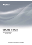
5HPRYDO3URFHGXUH
5HPRYDO3URFHGXUH
:DUQLQJ%HVXUHWRZDLWIRUDPLQLPXPRIPLQXWHVDIWHU
WXUQLQJRIIDOOSRZHUVXSSOLHVEHIRUHGLVDVVHPEO\
127(7DNHKHDWSXPSIRUH[DPSOH
Steps
Procedure
1.Remove filter 1
filter 1
Pull the clasp outwards, open filter 1
and then pull it outwards to remove it.
2.Remove filter 2
filter 2
Hold the clasp of filter 2 and then pull it
outwards to remove it.
3.Remove rear plate
rear plate
screw
Remove the 8 fixing screws, push the
rear plate upwards and then remove it
after the clasp is separated.
screw
5HPRYDO3URFHGXUH
Steps
Procedure
4. Remove left side plate and right side plate
screw
screw
Remove the 10 fixing screws (5 at the
left side and 5 at the right side); push
the side plate upwards and then
remove it after the clasp is separated.
right side plate
left side plate
5. Remove panel assy
screw
Remove the 4 fixing screws, rotate the
panel upwards slightly and then
remove it.
panel assy
5HPRYDO3URFHGXUH
Steps
Procedure
6. Remove top cover assy
top cover assy
screw
Remove the 4 fixing screws and then
remove the top cover assy.
7. Remove baffle
foam(baffle)
baffle
screw
Remove the foam, remove the 5 fixing
screws (3 screws are under the foam)
and then remove the baffle.
8. Remove support plate 2 and support plate 4
screw
support plate 4
Remove the 3 fixing screws and then
remove supporting plate 2 and 4.
support plate 2
5HPRYDO3URFHGXUH
Steps
Procedure
9. Remove evaporator assy
screw
welding joint
evaporator assy
Unsolder the welding joint connected
with the pipeline, remove the 2 fixing
screws and then remove the
evaporator assy.
10. Remove electric box assy
screw
electric box assy
Pull the clasp of electric box cover
outwards; remove the electric box
cover; remove the connection wire on
the PCB board; remove the 2 fixing
screws and then remove the electric
box assy.
clasp
electric box cover
11. Remove capacitor box sub-assy
capacitor box cover
screw
Remove the 2 screws fixing the cover
of capacitor box, remove the
connection wire on the capacitor and
then remove the cover of capacitor box;
remove the 1 screw fixing the capacitor
box and then remove the capacitor box
sub-assy.
screw
capacitor box
sub-assy
12. Remove supporting board 1, 2 and 3
supporting board 3
Remove the 6 fixing screws to remove
the supporting board 1, 2 and 3.
screw
supporting board 1
supporting
board 2
5HPRYDO3URFHGXUH
Steps
Procedure
13. Remove duct assy
screw
Remove the 2 fixing screws and then
remove the duct assy.
duct assy
14. Remove swing louver and swing lever
swing lever
Lift the swing louver upwards; bend the
swing louver to separate it from the
fixing hole; remove the swing louver;
pull the swing lever outwards to
remove the swing lever.
swing louver
15. Remove volute 1(upper) and grille
volute 1(upper)
screw
Remove the 3 fixing screws to take out
the volute 1(upper); remove the 2
screws fixing the grille to remove the
grille.
grille
5HPRYDO3URFHGXUH
Steps
Procedure
16. Remove centrifugal blade
centrifugal blade
nut
Remove the fixing nut and washer to
remove the centrifugal blade.
17. Remove volute 2(upper)
screw
volute 2(upper)
foam(connected to water tray)
Remove the 3 fixing screws to remove
the volute 2(upper) and then remove
the foam(connected to water tray).
18. Remove flow-guide loop
screw
Turn the duct assy upside down and
then remove the 3 fixing screws to
remove the flow-guide loop.
flow-guide loop
19. Remove centrifugal blade
nut
Remove the fixing nut and washer to
remove the centrifugal blade.
centrifugal blade
5HPRYDO3URFHGXUH
Steps
Procedure
20. Remove motor
screw
motor
motor base
Remove the 4 fixing screws to remove
the motor.
21. Remove condenser assy
welding joint
Unsolder the welding joint connected to
the pipeline; remove the 2 fixing
screws to remove the condenser assy
and pipeline.
screw
condenser assy
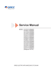
5HPRYDO3URFHGXUH
Steps
Procedure
22. Remove compressor
compressor
nut
Remove the 3 nuts fixing the
compressor and lift the compressor
upwards to remove it.
23. Remove water-striking motor
nut
nut
Remove the 4 screws fixing the
water-striking motor and water level
switch to remove the water-striking
motor and water level switch; turn the
chassis upside down and remove the
fixing screws(two for each castors) to
remove the cators.
water-striking switch
water-striking motor
chassis
castor
JF00301572
GREE ELECTRIC APPLIANCES, INC. OF ZHUHAI
Add: West Jinji Rd, Qianshan, Zhuhai, Guangdong, China, 519070
Tel: (+86-756) 8522218
Fax: (+86-756) 8669426
E-mail: [email protected] www.gree.com
For continuous improvement in the products, Gree reserves the right to modidy the product specification and appearance in this manual
without notice and without incurring any obligations.