1
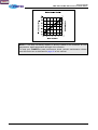
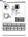
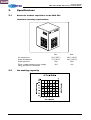
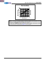
Back to top
Service manual
for the
FMIF 220 and FMIF 550
electronic modular flakers
UK trade spare parts and servicing
Menu
Service manual
FMIF 220 and FMIF 550 electronic modular flakers
Copyright
Copyright Foster Refrigerator (UK) Limited, November 2000
All rights reserved. No part of this publication may be reproduced, stored in a retrieval system, or
transmitted in any form or by any means, electronic, mechanical, photocopying, recording or
otherwise, without the prior permission of Foster Refrigerator (UK) Limited.
Foster Refrigerator (UK) Limited
Oldmedow Road
KING'S LYNN
PE30 4JU
United Kingdom
Tel: +44 (0) 1553 691122
Fax: +44 (0) 1553 691447
Web: www.fosterrefrigerator.co.uk
November 2000
Page ii
Menu
Service manual
FMIF 220 and FMIF 550 electronic modular flakers
Safety of personnel
Liability
Foster Refrigerator (UK) Limited decline responsibility when an attempt is made to use the
refrigerator for any purpose other than that for which it was designed.
WARNING!
THOSE WHO MAINTAIN THE REFRIGERATOR MUST BE TRAINED
IN STANDARD REPAIR AND MAINTENANCE PRACTICES AND
MUST
HAVE
READ
AND
UNDERSTOOD
THE
SAFETY
INSTRUCTIONS CONTAINED IN THIS MANUAL BEFORE
CARRYING OUT ANY MAINTENANCE.
Operating environment
Temperature
The Refrigerator must be used in a clean, well-lit environment with a stable temperature of
approximately 5°C to 35°C.
Relative humidity
The Refrigerator must be used in an environment with a relative humidity between 20% to 80%
(non-condensing).
Symbols and decals
Personnel must be familiar with all the warning symbols and decals fitted to the Refrigerator.
Failure to recognise a warning and read the associated safety instructions may result in injury or
death.
THIS DECAL IS USED TO INDICATE AN ELECTRICAL HAZARD.
THE REFRIGERATOR MUST BE DISCONNECTED FROM THE
MAINS ELECTRICAL POWER SUPPLY WHEN THIS DECAL IS
ENCOUNTERED DURING INSTALLATION AND MAINTENANCE.
Electrical hazard
WARNING!
THE REFRIGERATOR MUST BE DISCONNECTED FROM THE
MAINS ELECTRICAL POWER SUPPLY WHEN THIS DECAL IS
ENCOUNTERED DURING INSTALLATION, MAINTENANCE OR
SETTING-UP.
November 2000
Page iii
Menu
Service manual
FMIF 220 and FMIF 550 electronic modular flakers
Electro-static discharge (ESD)
CAUTION! Precautions against ESD must be taken to prevent damage to the Refrigerator
control circuits:
(1) Ensure that the operating environment is protected against ESD.
(2) Do not touch electronic circuits or wafers.
(3) Always use a grounded wrist strap while handling electronic circuits.
November 2000
Page iv
Menu
Service manual
FMIF 220 and FMIF 550 electronic modular flakers
1.
Specifications
1.1
Modular flaker model FMIF 220 electronic
Important operating requirements:
Air temperature
Water temperature
Water pressure
Electr. voltage variations from voltage
rating specified on nameplate
1.2
Min.
Max.
10°C (50°F)
5°C (40°F)
1 bar
-10%
40°C (100°F)
40°C (100°F)
5 bar
+6%
Ice making capacity
November 2000
Page 1
Menu
Service manual
FMIF 220 and FMIF 550 electronic modular flakers
NOTE — The daily ice-making capacity is directly related to the condenser air inlet
temperature, water temperature and age of the machine.
To keep your FLAKER at peak performance levels, periodic maintenance checks
must be carried out as indicated on page 46 of this manual.
November 2000
Page 2
Menu
Service manual
FMIF 220 and FMIF 550 electronic modular flakers
FMIF 220 machine specifications
Model
Cond. unit
Finish
Comp. HP
Water reg.
It/24hr
FMIF 220 AS
Air
S. Steel
1/2
200
FMIF 220 WS
Water
S. Steel
1/2
850*
Gas Charge
Standard
Supply
R22 480 grams 220/50/1 R22
R404A 880
grams
220/50/1
R404A
Start Amps
Run Amps
Watts
Fuse Rating
15.8
3.4
670
10 Amp
20
4
760
10 Amp
* At 15°C water temperature.
November 2000
Page 3
Menu
Service manual
FMIF 220 and FMIF 550 electronic modular flakers
2.
Specifications
2.1
Electronic modular superflaker model FMIF 550
Important operating requirements:
Air temperature
Water temperature
Water pressure
Electr. voltage variations from voltage
rating specified on nameplate
2.2
Min.
Max.
10°C (50°F)
5°C (40°F)
1 bar
-10%
40°C (100°F)
40°C (100°F)
5 bar
+6%
Ice making capacity
November 2000
Page 4
Menu
Service manual
FMIF 220 and FMIF 550 electronic modular flakers
NOTE — The daily ice-making capacity is directly related to the condenser air inlet
temperature, water temperature and age of the machine.
To keep your FLAKER at peak performance levels, periodic maintenance checks
must be carried out as indicated on page 46 of this manual.
November 2000
Page 5
Menu
Service manual
FMIF 220 and FMIF 550 electronic modular flakers
FMIF 220 machine specifications
Model
Cond. unit
Finish
Comp. HP
Water reg.
It/24hr
FMIF 220 AS
Air
FMIF 220 WS
Water
Gas Charge
Standard
Supply
R22 480 grams 220/50/1 R22
R404A 880
grams
220/50/1
R404A
S. Steel
1/2
200
850*
Start Amps
Run Amps
Watts
Fuse Rating
15.8
3.4
670
10 Amp
20
4
760
10 Amp
* At 15°C water temperature.
November 2000
Page 6
Menu
Service manual
FMIF 220 and FMIF 550 electronic modular flakers
3.
General information and installation
3.1
Introduction
This manual provides the specifications and the step-by-step procedures for the
installation, start up and operation, maintenance and cleaning for the Modular Ice
makers.
The Electronic Flakers are quality designed, engineered and manufactured. Their ice
making systems are thoroughly tested providing the utmost in flexibility to fit the needs
of a particular user.
This product qualifies for the following listings:
These ice makers have been engineered to our own rigid safety and performance
standards. The VDE-SEV-WRC seals signify that it is listed with them and that it
complies with the materials and manufacturing standards of them. These seals also
signify that these ice maker models have been inspected and tested by
VDE-SEV-WRC inspectors who reserve the right to periodically examine production ice
makers at the factory to assure continued compliance.
NOTE — To retain the safety and performance built into this ice maker, it is
important that installation and maintenence be conducted in the manner outlined in
this manual.
3.2
Unpacking and inspection
Ice maker
1.
Call your authorised Distributor or Dealer for proper installation.
2.
Visually inspect the exterior of the packing and skid. Any severe damage noted
should be reported to the delivering carrier and a concealed damage claim form
filled in subject to inspection of the contents with the carrier's representative
present.
3.
November 2000
a.
Cut and remove the plastic strip securing the carton box to the skid.
b.
Remove the packing nails securing the carton box to the skid.
c.
Cut open the top of the carton and remove the polystyrene protection
sheet.
d.
Pull out the polystyrene posts from the corners and then remove the
carton.
4.
Remove the front and side panels of the unit and inspect for any concealed
damage. Notify carrier of your claim for the concealed damage as stated in
step 2 above.
5.
Remove all internal support packing and masking tape.
6.
Check that refrigerant lines do not rub against or touch other lines or surfaces,
and that the fan blades move freely.
Page 7
Menu
Service manual
FMIF 220 and FMIF 550 electronic modular flakers
7.
Check that the compressor fits snugly onto all its mounting pads.
8.
See data plate on the rear side of the unit and check that local main voltage
corresponds with the voltage specified on it.
CAUTION — Incorrect voltage supplied to the icemaker will void your parts
replacement programme.
3.3
Location and levelling
CAUTION — This Modular Flaker is designed for indoor installation only.
Extended periods of operation at temperatures exceeding the following
limitations will constitute misuse under the terms of the FOSTER
Manufacturer's Limited Warranty resulting in LOSS of warranty coverage.
1.
2.
3.4
Position the storage bin in the selected permanent location. Criteria for
selection of location include:
a.
Minimum room temperature
temperature 40°C (100°F).
10°C
(50°F)
and
maximum
room
b.
Water inlet temperatures: minimum 5°C (40°F) and maximum 40°C
(100°F).
c.
Well ventilated location for air cooled models (clean the air cooled
condenser at frequent intervals).
d.
Service access: adequate space must be left for all service connections
through the rear of the ice maker. A minimum clearance of 15cm (6in)
must be left at the sides of the unit for routing cooling air drawn into and
exhausted out of the compartment to maintain proper condensing
operation of air cooled models.
Level the Storage Bin Assy in both the left to right and front to rear directions by
means of the adjustable legs.
Electrical connections
See data plate for current requirements to determine wire size to be used for electrical
connections. All Foster ice makers require a solid earth wire.
All Foster ice machines are supplied from the factory completely pre-wired and require
only electrical power connections to the wire cord provided at rear of the unit.
Make sure that the ice machine is connected to its own circuit and individually fused
(see data plate for fuse size).
The maximum allowable voltage variation should not exceed -10% and +13% of the
data plate rating. Low voltage can cause faulty functioning and may be responsible for
serious damage to the overload switch and motor windings.
NOTE — All external wiring should conform to national, state and local standards
and regulations.
Check voltage on the line and the ice maker's data plate before connecting the unit.
November 2000
Page 8
Menu
Service manual
FMIF 220 and FMIF 550 electronic modular flakers
3.5
Water supply and drain connections
General
When choosing the water supply for the ice flaker consideration should be given to:
•
Length of run
•
Water clarity and purity
•
Adequate water supply pressure. Since water is the most important single
ingredient in producing ice the three items listed above cannot be
over emphasised.
Low water pressure, below 1 bar may cause malfunction of the ice maker unit. Water
containing excessive minerals will tend to produce scale build-up on the interior parts
of the water system while too soft water (with too low contents of mineral salts), will
produce a very hard flaker ice.
Water supply
Connect the 3/4in GAS male of the water inlet fitting, using a food grade flexible tubing
or a 3/8in O.D. copper pipe, to the cold water supply line with regular plumbing fitting
and a shut-oft valve installed in an accessible position between the water supply line
and the unit.
If water contains a high level of impurities, it is advisable to consider the installation of
an appropriate water filter or conditioner.
Water supply - Water cooled models
The water cooled versions of Foster ice makers require two separate inlet water
supplies, one for the water making the flaker ice and the other for the water cooled
condenser.
Connect the 3/4in GAS male fitting of the water inlet, using flexible tubing or a 3/8in O.D.
copper pipe, to the cold water supply line with regular plumbing fitting and a shut-oft
valve installed in an accessible position between the water supply line and the unit.
Water drain
The recommended drain tube is a plastic or flexible tube with 18mm (3/4in) I.D. runs to
an open trapped and vented drain. When the drain is a long run, allow 3cm pitch per
metre (1/4in pitch per foot).
Install a vertical open vent on drain line high point at the unit drain connection to
ensure good draining.
The ideal drain receptacle is a trapped and vented floor drain.
Water drain - Water cooled models
Connect the 3/4in GAS male fitting of the condenser water drain, utilising a second
flexible tubing or a 3/8in O.D. copper tubing, to the open trapped and vented drain.
This additional drain line must not interconnect to any other of the unit's drains.
NOTE — The water supply and the water drain must be installed to conform with the
local code. In some cases a licensed plumber and/or a plumbing permit is required.
November 2000
Page 9
Menu
Service manual
FMIF 220 and FMIF 550 electronic modular flakers
3.6
Final checklist
1.
Is the unit in a room where ambient temperatures are within a minimum of 10°C
(50°F) even in winter months?
2.
Is there at least a 15cm (6in) clearance around the unit for proper air
circulation?
3.
Is the unit level? (IMPORTANT).
4.
Have all the electrical and plumbing connections been made, and is the water
supply shut-off valve open?
5.
Has the voltage been tested and checked against the data plate rating?
6.
Has the water supply pressure been checked to ensure a water pressure of at
least 1 bar (14psi).
7.
Have the bolts holding the compressor down been checked to ensure that the
compressor is snugly fitted onto the mounting pads?
8.
Check all refrigerant lines and conduit lines to guard against vibration and
possible failure.
9.
Have the bin liner and cabinet been wiped clean?
10. Has the owner/user been given the User Manual and been instructed on the
importance of periodic maintenance checks?
11. Has the manufacturer's registration card been filled in properly? Check for
correct model and serial number against the serial plate and mail the
registration card to the factory.
12. Has the owner been given the name and the phone number of the authorised
Foster Service Agency?
November 2000
Page 10
Menu
Service manual
FMIF 220 and FMIF 550 electronic modular flakers
3.7
Installation practice
CAUTION — This ice maker is not designed for outdoor Installation and will
not function In ambient temperatures below 10°C (50°F) or above 40°C (100°F).
This Ice maker will malfunction with water temperatures below 5°C (40°F) or
above 40°C (100°F).
November 2000
Page 11
Menu
Service manual
FMIF 220 and FMIF 550 electronic modular flakers
4.
Operating instructions
4.1
Start-up
After correctly installing the ice maker and completing the plumbing and electrical
connections, perform the following 'Start-up' procedure:
•
Open the water supply line shut-off valve and put the unit under electrical power
by moving the main switch, on the power supply line, to the ON position.
The first LED - GREEN - will glow to signal that unit is under power.
NOTE — Every time the unit is put under power, after being kept for some time in
shut-off conditions (electrically disconnected) the RED LED, will blink for 3 minutes
after which the unit will start up with the immediate operation of the gear motor
assembly and, after 5 seconds, the compressor assy (Fig. 1).
•
•
When 3 minutes have elapsed - stand-by period - the unit starts operating with
sequential activation of the following assemblies:
–
GEAR MOTORS
–
COMPRESSOR
–
FAN MOTORS (if the unit air-cooled). These are controlled by the
condenser temperature sensor which has its probe within the condenser
fins (Fig. 2).
After 2 or 3 minutes have elapsed from the compressor start-up, observe that
flaker ice begins falling from the ice spout, through the ice chute, into the
storage bin.
NOTE — The first ice flakes which fall into the ice storage bin are not very hard as
the evaporating temperature has not yet reached the correct operating value. It is
necessary to allow the ice - just made - to cure, and wait approximately ten minutes
for the evaporating temperature to reach the correct value thus making harder ice.
November 2000
Page 12
Menu
Service manual
FMIF 220 and FMIF 550 electronic modular flakers
November 2000
Page 13
Menu
Service manual
FMIF 220 and FMIF 550 electronic modular flakers
November 2000
Page 14
Menu
Service manual
FMIF 220 and FMIF 550 electronic modular flakers
NOTE — If, after ten minutes from the compressor start-up, the evaporating
temperature has not dropped down to a value lower than -1°C (30°) (due to
insufficient refrigerant in the system or excessive condensing temperature) the
evaporating temperature sensor detects an abnormal condition and consequently
stops the unit operation. If this occurs, the 5th warning YELLOW LED will blink
(Fig. 3).
After diagnosing and eliminating the cause the abnormal condition it is necessary to
restart the unit by pushing the RE-SET BUTTON which protrudes through a hole in
the control box cover. The unit, before resuming the total operation, will go through
the usual 3 minutes STAND-BY period.
4.2
Operation checks on unit start-up
1.
Remove front service panel and, if necessary, install the refrigerant service
gauges on the corresponding Schrider valves to check both the HI and LO
refrigerant pressures.
NOTE — On air cooled models, the head (condensing) pressure is maintained
between 13.5 and 14.5 bar (190-205psig). This is controlled according to the
condenser temperature sensor, which is located within the condenser fins.
In the event of the condenser becoming clogged - sufficiently to prevent the proper
flow of the cooling air - or in the case of the fan motor being out of operation, the
condenser temperature rises and when it reaches 70°C (160°F) for air-cooled
versions and 62°C (145°F) - for water-cooled versions - the condenser temperature
sensor shuts-off the ice maker and illuminates the RED WARNING LIGHT (Fig. 4).
After diagnosing and eliminating the cause of the temperature rise is necessary to
proceed as per the previous 'NOTE' to start-up again the operation of the ice maker.
November 2000
Page 15
Menu
Service manual
FMIF 220 and FMIF 550 electronic modular flakers
2.
Check for correct CUT-OUT and CUT-IN of the float reservoir water level
sensors by first closing the water shut-off valve on the water supply line.
This will cause a gradual decrease of the water level in the float reservoir and
as soon as the level falls below the sensors, the flaker stops operating and the
YELLOW warning LED glows to signal the shortage of water (Fig. 5).
November 2000
Page 16
Menu
Service manual
FMIF 220 and FMIF 550 electronic modular flakers
NOTE — The water level sensor detects the presence of sufficient water in the float
reservoir and confirms it to the microprocessor by maintaining a low voltage current
flow between the two sensors using the water as a conductor.
CAUTION — The use of de-mineralised water (water with no salt content) having an
electrical conductivity lower than 30µS, will reduce, or even eliminate the effectivity
of the water sensors. Consequently, the microprocessor will shut off the unit and
illuminate the YELLOW LED thus indicating shortage of water regardess of the
actual water level in the reservoir
After this open the water supply line shut-off valve to refill the float reservoir, the
YELLOW LED goes off and the RED LED starts blinking. After 3 minutes the
unit resumes its normal operation with the immediate start-up of the gear motor
and, 5 seconds later, the compressor.
3.
Check for the correct operation of the electronic eye (one per each ice chute on
model MF61) for the ice bin level control, by placing one hand between the
sensing 'eyes' located in the ice spout, to interrupt the light beam.
This interruption will cause an immediate extinguishing of the RED LED located
on the front of the P.C. Board and after about 10 seconds causes the shut-oft
of the unit with the simultaneous lighting of the YELLOW LED signalling the full
bin situation (Fig. 6).
November 2000
Page 17
Menu
Service manual
FMIF 220 and FMIF 550 electronic modular flakers
Allow the resumption of the light beam previously interrupted and after about 10
seconds the flaker will resume - through the 3 minutes STAND-BY period - the
ice making process with the extinguishing of the YELLOW LED.
NOTE — The ICE LEVEL CONTROL (INFRA RED SYSTEM) is independent of the
temperature, however, the reliability of its detection can be affected by external light
radiations or by any sort of dirt and scale sediment which may be deposited directly
on the light source and on the receiver.
To prevent any possible ice maker malfunction, due to negative affect of the light
detector, it is advisable to locate the unit where it is not reached by any direct light
beam or light radiation, also it is recommended to keep the bin door constantly
closed and to follow the instructions for the periodical cleaning of the light sensor
elements as detailed in the MAINTENANCE AND CLEANING PROCEDURES.
November 2000
4.
If previously installed, remove the refrigerant service gauges and re-fit the unit
service panels previously removed.
5.
Instruct the owner/user on the general operation of the ice machine and about
the cleaning and care it requires
Page 18
Menu
Service manual
FMIF 220 and FMIF 550 electronic modular flakers
5.
Principle of operation
5.1
Water circuit
The water enters the machine through the water inlet fitting which incorporates a
strainer and is located at the rear side of the cabinet and then passes through a float
valve to the water reservoir.
NOTE — The presence of water in the float reservoir is detected by a system of two
sensors which operate in conjunction with the P.C. Board. The two sensors use the
water as a conductor to maintain a low voltage current flow between them signalling
in this way to the P.C. Board the presence of the water in the reservoir. If the water
used is very soft (de-mineralised) or the float reservoir becomes empty the current
flow between the sensors becomes so weak or that the P.C. board shuts off the
flaker operation with the simultaneous glowing of the YELLOW LED signalling
'shortage of water.
The float reservoir is positioned at the side of the freezing cylinder at such a height to
be able to maintain a constant water level around the freezer auger. In fact, the water
flows from the reservoir into the bottom inlet of the freezing cylinder to surround the
stainless steel auger which is vertically fitted in the centre of the freezer.
The incoming water gets chilled in the freezer into soft (slush) ice which is moved
upward by the rotating action of the auger. The stainless steel auger, which rotates
counter-clockwise within the freezer, is powered by a direct drive gear motor and
carries the ice upward along the refrigerated freezer inner walls and by doing so the
ice gets progressively thicker and harder.
The ice, being constantly lifted up, meets the teeth of the ice breaker which is fitted on
the top end of the auger, where it becomes compacted, cracked and forced to change
from vertical into horizontal motion to be discharged out, through the ice spout and
chute, into the storage bin.
Start-up of the ice maker, i.e. putting the unit under power, starts the automatic and
continuous ice making process which does not stop until the ice storage bin gets filled
to the level of the control 'eyes' located on the sides of the ice chute. The rising ice
level interrupts the light beam running between the two infra red lamps. Ten seconds
later the unit stops with the simultaneous glowing of the YELLOW LED signalling the
'Full Bin' condition.
NOTE — Interruption of the light beam between the two light sensors is immediately
signalled by extinguishing of the RED LED located on the front of the P.C. Board.
After about 10 sec of steady interruption of the light beam the unit stops and the
'Full Bin' YELLOW LED glows.
The ten second delay prevents the unit from stopping for any undue reason like the
momentary interruption of the light beam caused by flakes which slide along the ice
spout before dropping into the bin.
As some ice gets scooped out from the storage bin, the light beam between the two
sensors resumes and immediately the RED LED in the front-centre of the P.C. Board
lights-up; ten seconds later the ice machine restarts the ice making process and the
YELLOW LED goes off.
November 2000
Page 19
Menu
Service manual
FMIF 220 and FMIF 550 electronic modular flakers
5.2
Refrigerant circuit
The hot gas refrigerant discharged from the compressor reaches the condenser
where, being cooled down, condenses into liquid.
Flowing into the liquid line it passes through the dryer filter, then passes through the
capillary tube where it loses some of its pressure so that its pressure and temperature
are lowered. Next, the refrigerant enters the evaporator coil wrapped around the
freezer inner tube.
The water being constantly fed at the interior of the freezer inner tube, exchanges heat
with the refrigerant circulating into the evaporator coil. This causes the refrigerant to
boiloff and evaporate, thereby changing from liquid into vapour.
The vapour refrigerant then passes through the suction accumulator and through the
suction line where the refrigerant exchanges heat with the one flowing into the capillary
tube (warmer) before being sucked into the compressor to be re-circulated.
The refrigerant head pressure is kept between two pre-set values 13.5 and 14.5 bar
(190-205psig) by the condenser temperature sensor which has its probe located within
the condenser fins - in air cooled versions.
November 2000
Page 20
Menu
Service manual
FMIF 220 and FMIF 550 electronic modular flakers
This condenser temperature sensor, when sensing a rise in condenser temperature
beyond the pre-fixed limit, changes its electrical resistance and sends a low voltage
power flow to the microprocessor of the P.C. Board which energises, through a TRIAC,
the Fan Motor in ON-OFF mode.
When the opposite situation occurs, i.e. the condenser temperature falls below the
pre-fixed limit, the temperature sensor changes again its electrical resistance thereby
reducing the current flow to the P.C. Board and causing a temporary stop of the Fan
Motor.
On the water cooled versions, the refrigerant head pressure is kept at the constant
value of 14 bar (195psig) by the metered amount of water passing through the
condenser which is regulated by the action of the Water Regulating Valve that has its
capillary tube connected to the liquid refrigerant line. As pressure increases, the water
regulating valve opens to increase the flow of cooling water to the condenser.
NOTE — If the condenser temperature probe senses that the condenser
temperature has risen to 70°C (160°F), in the air-cooled version, or 62°C (145°F) - in
the water-cooled version - the temperature increase may occur for one of the
following abnormal reasons:
•
CLOGGED CONDENSER (Air-cooled version)
•
INSUFFICIENT FLOW OF COOLING WATER (Water-cooled version)
•
FAN MOTOR OUT OF OPERATION (Air-cooled version)
•
AMBIENT TEMPERATURE HIGHER THAN 43°C (110°F).
Any of the above abnormalities will cause the total and immediate SHUT-OFF of the
machine in order to prevent the unit from operating in abnormal and dangerous
conditions.
When the ice maker shuts off under these conditions there is a simultaneous,
illumination of the RED LED, warning the user of the Hi Temperature condition.
After eliminating the cause of the excessive condenser temperature, restart the ice
machine by pushing the RE-SET button which protrudes through the control box
cover.
The RED LED starts blinking and three minutes later the flaker unit resumes its
normal operating mode. The condenser temperature sensor has a further safety
function which prevents the unit from operating in Lo-ambient conditions i.e. when
the condenser body temperature - equivalent to the ambient temperature - is lower
then 1°C (34°F) (Fig. 7).
Even in this situation, it is possible able to run the machine, after correcting the Lo
ambient condition, by pressing the RE-SET Push Button.
November 2000
Page 21
Menu
Service manual
FMIF 220 and FMIF 550 electronic modular flakers
In normal ambient conditions the refrigerant (or Lo-pressure) values are set to
2.0-2.5bar (28-35psig) a few minutes after start-up. This value can vary by 0.1 or 0.2
bar (1.5-3psig) according to variations in water temperature which influence the freezer
cylinder.
NOTE — If, after ten minutes from start-up, no ice is made and the evaporating
temperature detected by the evaporator sensor exceeds -1°C (30°F) the ice maker
stops and the 5th WARNING YELLOW LED blinks.
5.3
Mechanical system
The mechanical system of the Foster Flaker machines comprises a gear motor
assembly which drives, through a ratched coupling, a worm shaft or auger placed on
its vertical axis within the freezing cylinder.
The gear motor comprises a single phase electric motor with a permanent capacitor.
This motor is directly fitted to the gear case through which it drives - in counter
clockwise rotation at a speed of 9.5rpm - the freezer auger being linked to it by the
ratched coupling.
November 2000
Page 22
Menu
Service manual
FMIF 220 and FMIF 550 electronic modular flakers
NOTE — If the gear motor rotates in the wrong direction (counter-clockwise) the
unit, will stop immediately with the glowing of the WARNING YELLOW LED due to
the intervention of the Electromagnetic Safety Device - based on Hall Effect
principle.
After diagnosing and eliminating the cause of the gear motor wrong rotation, restart
the unit by pressing the RE-SET push button or switch OFF and ON the power line
main disconnect switch (Fig. 8).
The RED LED will start blinking and after 3 minutes the ice maker will resume its
normal operation by running first the gear motor and then the compressor.
Too low ambient and water temperature (well below the limitations of 10°C (50°F) and
5°C (40°F) respectively) or frequent interruptions of the water supply to the freezing
cylinder due to clogging of the water hose which connects the float reservoir to the
water inlet at the bottom of the freezer may cause the ice to get too hard and compact,
thereby losing fluidity and causing a seize-up of the auger.
This situation will cause excessive strain and load the entire drive system and freezer
bearings.
When the gear motor rotating speed is slowed below 1300rpm from the normal speed
of 1400rpm the Electromagnetic Safety Device responds in the same manner as the
auger wrong rotation condition and the microprocessor immediately stops unit
operations with the lighting-up of the YELLOW WARNING LED. This action relieves
excessive load from all electrical and mechanical components of the entire Drive
System.
November 2000
Page 23
Menu
Service manual
FMIF 220 and FMIF 550 electronic modular flakers
NOTE — After diagnosing and eliminating the cause of the gear motor slow rotation,
restart the unit by pressing, the RE-SET push button or switch OFF and ON the
power line main switch.
5.4
Operating characteristics
The electrical components in operation are:
•
COMPRESSOR
•
GEAR MOTOR/S
•
FAN MOTOR/S (on air-cooled versions)
On air-cooled models during the freezing cycle the discharge pressure is maintained
between 13.5 and 14.5 bar (190-205psig) by the condenser temperature sensor.
On water-cooled models, the discharge pressure is constantly maintained by the water
regulating valve at 14 bar (195psig).
The refrigerant suction pressure remain virtually constant (2-2.5 bar -28-35psig) during
the entire ice making process; it may vary slightly (+0.2 bar - 3psig) in relation to the
water supply temperature variation.
Even the amps drawn by the compressor remain at a constant value.
Refrigerant metering device
Capillary tube
Refrigerant charge (R 22)
Air-cooled
Water cooled
FMIF 220
480 gr
480 gr
FMIF 550
950 gr
950 gr
For R404A - Refer to refrigerant charge table
NOTE — Before charging the refrigerant system always check the type of
refrigerant and quantity as specified on the individual ice machine data plate. The
refrigerant charges indicated are relative to average operating conditions.
Operating pressures (with 210°C ambient temperature)
Discharge pressure:
Air cooled version
Water cooled version
Suction pressure:
November 2000
FMIF 220
IFMIF 550
15 bar
13.5-14.5 bar
210psig
190-205psig
14 bar
14 bar
195psig
195psig
2.5±0.2 bar
2.0±0.2 bar
35±3psig
28±3psig
Page 24
Menu
Service manual
FMIF 220 and FMIF 550 electronic modular flakers
6.
Component description
6.1
Evaporator temperature sensor
The evaporator sensor probe is inserted in its tube well, which is welded on the
evaporator outlet line. It monitors the temperature of the refrigerant leaving the
evaporator and passes the information via a low voltage current flow to the P.C. Board
microprocessor.
According to the current received, the microprocessor allows the ice maker, to
continue its operations. If the evaporating temperature, after 10 minutes from the unit
start-up, does not fall below -1°C (30°F) due to shortage of refrigerant in the system or
due to the excessive condensing temperature, the evaporator immediately stops unit
operation, and illuminates the 5th Warning YELLOW LED, which blinks.
6.2
Float reservoir water sensor system
This sensor system consists of two small stainless steel rods vertically fitted on the
inner face of the reservoir cover and electrically connected to the low voltage circuit of
the P.C. Board. When the cover of the reservoir is in place the tips of both the rods
dip into the reservoir water and detect and signal its presence by making use of its
electrical resistance.
NOTE — In the event of shortage of water in the reservoir or, if the water used is
too soft (de-mineralised with conductivity lower than 30pS) this sensor system
causes the shut off of the machine, to protect it from running with an interrupted or
inadequate water supply.
In this situation the YELLOW LED will glow to warn of the machine shut-off and the
reason why.
6.3
Condenser temperature sensor
The condenser temperature sensor probe, located within the condenser fins
(air-cooled version) or in contact with the tube coil (water-cooled version) detects the
condenser temperature variations and signals them by supplying current, at low
voltage, to the P.C. BOARD.
If the condenser temperature sensor detects a temperature at the condenser lower
than +1°C (33°F) this implies that the ambient temperature is at the same value,
therefore, it is too low for correct unit operation. The sensor signals to the
microprocessor to stop immediately or not start the unit operations up until the ambient
temperature rises to more acceptable terms (10°C).
In air-cooled versions, the microprocessor on the P.C. BOARD controls the condenser
fan motor via a TRIAC which varies the high voltage supply to the fan motor according
to variations in the signal from the condenser temperature sensor.
If the condenser temperature rises and reaches 70°C (160°F) - on air cooled versions 62°C (145°F) - on water cooled versions - the condenser temperature sensor signal
received at the microprocessor causes an immediate and total stop of machine
operation .
November 2000
Page 25
Menu
Service manual
FMIF 220 and FMIF 550 electronic modular flakers
NOTE — To restart the unit after a shut-off caused by the condenser temperature
sensor for any one of the two abnormal situations previously described, it is
necessary to push the RE-SET button (after diagnosing and correcting the causes of
unit stoppage) or switch OFF and ON the power line main disconnect switch.
6.4
Gear motor rotation and speed sensor
This safety device is housed on top of the Drive Motor and detects - using the Hall
Effect principle - the rotation speed and rotation direction of the drive motor.
If the rotating speed drop below 1300rpm the magnitude measured by this device
causes the microprocessor to stop the unit and illuminate the YELLOW LED. The
same reaction occurs when the drive motor tends to rotate in the wrong direction
(counter-clockwise) situation. A condition which, if it occurs, will greatly affect all the
freezer and gear reducer components.
NOTE To restart the unit after the shut-off by this safety device, it is necessary first
to eliminate the cause and then press the RE-SET push button or switch OFF and
ON the power line main disconnect switch.
6.5
Ice bin level light control
The purpose of the electronic ice bin level control, located in the ice chute, is to stop
the operation of the ice machine when the light beam between the light source and the
sensor is interrupted by flake ice which accumulates in the chute.
When the light beam is interrupted the RED LED located in the front of the P.C.
BOARD goes off. If the light beam is interrupted for longer than 10 seconds, the ice
machine stops with the 2nd YELLOW LED illuminated to indicate to a full ice bin
situation.
The 10 seconds of delay allows for intermittent interruption of the light beam due to
normal ice movement through the ice chute before the ice bin is full. This ensures that
shut-off will only occur when the ice bin is full.
As soon as ice is scooped from the ice bin the light beam between the two infra red
sensors of the ice level control is no longer interrupted, therefore, the RED LED lights
up and after 10 seconds the ice machine resume its operation with the simultaneous
extinguishing of the 2nd YELLOW LED.
6.6
P.C. board (data processor)
The P.C. BOARD, in its plastic box located in the front of the unit, comprises two
separated printed circuits one at high and the other at low voltage, protected by three
fuses, integrated with a RE-SET button. The P.C. BOARD incorporates on-board
servicing facilities which include the following:
November 2000
•
A set of five in-line LEDS which indicate the operating status of the machine
•
One RED LED which indicate the operating status of the machine
•
One DIP SWITCH, with eight keys
•
Input terminals for connection of two sensor probes
•
Input and output electrical connection terminals for electrical devices within the
unit which are interfaced with the .P.C. BOARD
Page 26
Menu
Service manual
FMIF 220 and FMIF 550 electronic modular flakers
The P.C. BOARD is the heart of the control system which processes signals received
from the sensors to control the operation of the different electrical components of the
ice maker (compressor, gear motor, etc.).
The five LEDS, placed in a row in the front of the P.C. BOARD, monitor the following
situations:
GREEN LIGHT
Unit under electrical power
YELLOW LIGHT
Unit shut-off at full storage bin
YELLOW LIGHT
Unit shut-off due to inadequate Lo-water level condition in the float tank
RED LIGHT
Unit shut-off due to excessive hi-condensing temperature
Unit shut-off due to an inadequate Lo-ambient temperature <+1°C
YELLOW LIGHT
Unit shut-off due to the wrong rotation direction of gear motor
Unit shut-off due to inadequate speed of gear motor
Unit shut-off due to an excessive hi-evaporating temperature >-1°C
after 10 minutes of operation.
6.7
Dip switch
The P.C. Board which controls the entire operation of the ice maker, has a DIP
SWITCH with eight switching keys (see table) which allow changes to be made to the
function and set-up of some of the system controls as described in details below.
DIP SWITCH key 1, when set to the ON position, allows the skipping of the 3 minutes
delay period at the start-up of the Ice Maker.
NOTE — To prevent the unit be subject to startings and stoppings in rapid sequence
it is strongly recommended to keep this key in OFF position.
DIP SWITCH key 2, when set to the ON position, allows rapid auto-diagnosis of the
P.C. Board outputs to compressor, gear motor and fan motor, by energising them in
rapid sequence (2 seconds) one at the time, to make sure of their operation.
DURING THE AUTOMATIC OPERATION OF THE ICE MAKER THIS KEY MUST BE
SET IN OFF POSITION.
CAUTION — This auto-diagnosis must he performed in the shortest possible
time in order to avoid frequent startings and stoppings of the electrical
components which may cause damage to their windings and controls.
November 2000
Page 27
Menu
Service manual
FMIF 220 and FMIF 550 electronic modular flakers
DIP SWITCH key 3, controls the rotation direction of the gear motor using the
electromagnetic control device based on the Hall effect. When set to the ON position
the gear motor to turns in the clockwise direction. When set to the OFF position the
gear motor turns in the counter-clockwise direction. In normal operation the gear
motor rotates in the clockwise direction, therefore, DIP SWITCH key 2 is normally
set to the ON position.
However, if DIP SWITCH key 3 is inadvertently left in the OFF position, start-up is
disabled.
DIP SWITCH key 4, allows the switching of the unit re-set from manual (OFF setting)
to automatic (ON setting) when the machine operation has been shut-off by any of
the safety control devices.
DIP SWITCH keys 5, 6 and 7 may be used to vary the temperature differential
determined by the condenser temperature sensor for the cut-in and cut-out of the fan
motor, as indicated in the following table.
The ideal combination which ensures the best performance of the ice maker is the first
one on the table, which gives a differential equal to 0.5°C from cut-in and cut-out of the
fan motor to keep the condensing temperature and pressure as straight as possible.
Differential Variations of Condenser Temperature Sensor according to the DIP SWITCH Key Setting
Combinations
5
ON
OFF
ON
OFF
ON
OFF
ON
OFF
6
ON
ON
OFF
OFF
ON
ON
OFF
OFF
7
ON
ON
ON
ON
OFF
OFF
OFF
OFF
DELTA T (°C)
0.5
1.0
1.5
2.0
2.5
3.0
3.5
4.0
ON position, or to 62°C (145°F), OFF position.
DIP SWITCH FACTORY SETTING COMBINATIONS
6.8
DIP SWITCH
1
2
3
4
5
6
7
8
Air-cooled
OFF
OFF
ON
OFF
ON
ON
ON
ON
Water-cooled
OFF
OFF
ON
OFF
ON
ON
OFF
OFF
Float reservoir
The float reservoir consist of a plastic water pan on which is fitted a float valve with its
setting screw. The float valve regulates the incoming water flow to maintain a constant
water level in the reservoir, a level which corresponds to the level in the freezing
cylinder to ensure proper ice formation and fluidity.
On the inner side of the reservoir cover are fitted the two water level sensors which
detect the presence or the shortage of water in the reservoir.
NOTE — It is very important to make sure of the correct fitting of the cover on the
reservoir in order to enable the sensor to efficiently control the water situation
avoiding undue shut-off interventions.
November 2000
Page 28
Menu
Service manual
FMIF 220 and FMIF 550 electronic modular flakers
6.9
Freezing cylinder or evaporator
The freezing cylinder, or evaporator, comprises a stainless steel vertical tube, which
houses the auger and an integral helical cooling coil surrounding the exterior of the
tube. Ice forms within the freezing cylinder due to heat transfer, from the freezing
cylinder to the cooling coil.
Within the freezing cylinder, the auger rotates on its vertical axis, supported and
aligned by top and bottom bearings.
Throughout the freezing process, newly formed ice is lifted upwards by the constantly
rotating auger and fed into the ice breaker at the top of the freezing cylinder.
The bottom of the freezing cylinder is fitted with a water seal system.
6.10
Ice breaker
The ice breaker is fitted in the upper part of the freezing cylinder. On the FMIF 220
Model, the ice breaker incorporates two breaker teeth, shaped and aligned so that the
ice is compacted, broken and forced out horizontally. On the other models the ice
breaker incorporates several rectangular openings, on its external circumference,
through which the ice is forced.
Whilst undergoing the breaking process the ice loses its excess of water content and
falls into the bin as hard, dry particles. These bearings are lubricated by a food
grade/water resistant grease.
NOTE — It is advisable to check the condition of both the lubricant grease and the
bearings every six months.
6.11
Drive gear and motor
The drive gear and motor assembly comprises a single phase electric motor, with
permanent capacitor, and a directly coupled reduction gear box.
The drive motor rotor is aligned on its vertical axis by two ball bearings which are
permanently lubricated. The reduction gear case contains a train of three spur gears
the first of which is made of fibre to limit noise level. All three gears are enclosed in
case bearings and are lubricated by grease (MOBILPLEX [P 44).
Two seal rings, one fitted on the rotor shaft and the other on the output shaft keep the
gear case sealed.
The aluminium gear case is of split case construction to allow inspection and
maintenance.
6.12
Fan motor (air-cooled version)
The fan motor is controlled by by the condenser temperature sensor via the TRIAC on
the P.C. BOARD. Normally it draws cooling air through the condenser fins.
In cold ambient temperatures the fan motor runs intermittently as the condenser
pressure must be kept between two corresponding head pressure values (13.5-14.5
bar - 190-205psig).
November 2000
Page 29
Menu
Service manual
FMIF 220 and FMIF 550 electronic modular flakers
6.13
Water regulating valve (water-cooled version)
The water regulating valve controls head pressure in the refrigerant system by
regulating the flow of water going to the condenser.
As pressure increases, the water regulating valve opens to increase the flow of cooling
water.
6.14
Compressor
The principal component of the refrigeration system is the hermetic compressor which
circulates refrigerant throughout the entire system. It compresses the low pressure
refrigerant vapour causing its temperature to rise and become high pressure hot
vapour which is then released through the discharge valve.
REFRIGERANT CHARGE R404A
AIR COOLED
Model
Gas Charge
FMIF 220
540 Grams
FMIF 550
880 Grams
OPERATING PRESSURE
21°C AMBIENT/ 15°C WATER TEMPERATURE
November 2000
Model
CONDENSER
SUCTION
FMIF 220
17/18 bar
2.5 bar
FMIF 550
17/18 bar
2.5 bar
Page 30
Menu
Service manual
FMIF 220 and FMIF 550 electronic modular flakers
7.
Adjustment, removal and
replacement procedures
NOTE — Read the instructions thoroughly before performing any of the following
adjustment or removal and replacement procedures.
7.1
Adjustment of the evaporator water level
The correct water level in the freezing cylinder is about 20mm (1 in) below the ice
discharge opening. Low water level causes excessive strain inside the freezer
assembly due to a faster freezing rate.
When the water level is above or below the correct one, adjustment can be performed
to raise or lower the water level by raising or lowering at the measure required, the
water reservoir and its mounting bracket.
To raise the water level:
•
Loosen and remove the screw securing the mounting bracket of the water
reservoir to the unit cabinet and raise the water reservoir to the correct level.
•
Thread the mounting screw in the corresponding hole and tighten it.
To lower the water level
•
follow the above instructions to lower to the correct level the water reservoir
assembly.
WARNING — Be sure the electrical power supply circuit breaker and the inlet
water supply are OFF, before starting any of the following Removal and
Replacement procedures as a precaution to prevent possible personal injury
or damage to the equipment.
7.2
Replacement of the evaporator temperature sensor
November 2000
1.
Remove the front/top panel.
2.
Remove the insulation from the refrigerant tubing, connecting the freezer to the
accumulator, to gain access to the sensor probe well and be able to pull out
from this well the sensor probe.
Page 31
Menu
Service manual
FMIF 220 and FMIF 550 electronic modular flakers
7.3
3.
Trace the condenser sensor terminal plug on the rear side of the control box
and remove it from its socket by carefully pulling out the terminal plug securing
clip.
4.
To install the replacement evaporator sensor follow the above steps in reverse.
Replacement of the condenser temperature sensor
1.
Remove the front /top panel.
2.
Trace the condenser sensor probe located within the condenser fins on air
cooled version and withdraw it.
3.
On water cooled version remove it by opening the plastic strap (re-usable)
securing the probe to the refrigerant liquid line.
4.
Trace the condenser sensor terminal plug on the rear side of the control box
and remove it from its socket by carefully pulling out the terminal plug securing
clip.
5.
To install the replacement condenser sensor follow the above steps in reverse.
NOTE — Both the condenser and the water level sensors have the same terminal
plug and socket. To avoid confusion when performing their replacement pay
attention to the different colour of the terminal plug and socket.
7.4
7.5
Replacement of the ice level light control
1.
On FMIF 220 and FMIF 550 remove the front/top panel.
2.
Locate the ice level light control terminal plug (black and with four terminal pins)
on the rear side of the control box and draw it out from its socket by carefully
slackening the fastening tie.
3.
Remove and withdraw, from the holes pierced on opposite sides of the plastic
ice chute, the two ice level light controls. Press their rubber holders on their
external edge/rim paying attention to not damage the infra red LED.
4.
To install the replacement ice level light control follow the above steps in
reverse.
Replacement of the gear motor rotation and speed sensor
November 2000
1.
On FMIF 220, and FMIF 550 remove the front/top and side/rear panels.
2.
Loosen three screws securing the plastic cover to the gear motor speed sensor
housing and remove it.
3.
Loosen two screws securing the sensor to the plastic housing and withdraw it
from its seat.
4.
Locate the gear motor speed sensor terminal plug on the rear side of the
control box and draw it out from its socket by carefully slackening the fastening
tie.
5.
To install the replacement gear motor rotation and speed sensor follow the
above steps in reverse.
Page 32
Menu
Service manual
FMIF 220 and FMIF 550 electronic modular flakers
7.6
7.7
7.8
Replacement of the reservoir water level sensor
1.
Remove the front/top panel.
2.
Loosen the two nuts securing the wire leads to the two water level sensor rods
located on the water reservoir plastic cover.
3.
Trace the water level sensor terminal plug on the rear side of the control box
and draw out from its socket by carefully slackening the fastening tie.
4.
To install the replacement water level sensor follow the above steps in reverse.
Replacement of P.C. board
1.
Remove front/top panel.
2.
Remove all sensor terminal plugs, located on the rear side of P.C. Board, by
carefully releasing them from their sockets clips.
3.
Disconnect the terminal board connection plug from the rear side of P.C.
BOARD then loosen the four screws holding the same to the plastic control box
and remove it.
4.
To install the replacement P.C. BOARD follow the above steps in reverse.
Replacement of the ice spout
1.
Remove the front/top panel.
2.
Loosen the wing nut and remove the ice chute from the ice spout paying
attention to avoid damaging the ice level light control.
3.
Slacken and remove two straps which secure the polystyrene insulations
against the freezer upper part.
4.
On model FMIF 220 unscrew the stainless steel spout from the brass casting.
On model FMIF 550 unscrew the bolts securing it to the ice breakers.
5.
On model FMIF 220 loosen and remove the two screws and separate the spout
casting from the freezer cylinder.
NOTE — On model FMIF 220 inspect the spout gasket and replace it if torn, cut or
worn. Otherwise, retain it for re-use.
6.
7.9
To install the replacement spout follow previous steps in reverse.
Replacement of the auger, water seal, bearings and
coupling
November 2000
1.
Remove the front/top panel.
2.
Remove the ice spout as described above.
3.
Loosen and remove two screws and washers securing the spout bracket to the
freezing cylinder.
4.
Grasp the wire cap hook at the top of the freezer and pull out the auger and
attached cap, ice breaker, bearings and O rings, at the top of the auger, and
the top half of the water seal at the auger bottom.
Page 33
Menu
Service manual
FMIF 220 and FMIF 550 electronic modular flakers
NOTE — If the auger cannot be pulled out, proceed to steps 10 and 11 in this
paragraph, to gain access to the bottom of the auger. Then, using a rawhide mallet
or similar, tap the bottom to free and pull it out as in step 4 above.
5.
On model FMIF 220 remove the retaining ring and cap hook from the ice
breaker using circlip pliers. On model FMIF 550 remove the plastic cap using a
screwdriver as a lever.
6.
Loosen and remove cap screw and remove the ice breaker from the auger.
7.
Clean away old grease from the interior of the ice breaker and inspect the
conditions of the O ring. If torn or worn replace it.
8.
Inspect the bearing pressed into the top of the ice breaker and, if worn, replace
it.
CAUTION — The top bearing assembly functions in a harsh operating environment
where a considerable amount of condensate is present. Before installing the
breaker and cap hook it is essential that the top bearing assembly is liberally coated
with Food grade Waterproof Grease.
9.
Slide the upper half of the water seal off the bottom end of the auger.
NOTE — Any time the auger is removed for replacement or inspection use extra
care in handling the water seal parts so that no dirt or foreign matter is deposited on
the sealing surfaces. If there is any doubt about the effectiveness of the water seal
or O ring do not hesitate to REPLACE THEM.
10. Loosen and remove three/four bolts and lockwashers which attach the freezer
assy to the aluminium adaptor.
11. Lift the freezer assy off the adaptor secure it in a position which allows room to
work. Using a wooden dowel or stick of suitable length and size inserted
through the top of the open freezer, tap the lower half of the water seal and the
lower bearing out the bottom of the freezer.
12. On model FMIF 550, remove the lo bearing brass holding ring from the bottom
of the freezer assy using two screwdrivers as levers.
NOTE — It is good practice to replace the water seal assy and both the top and the
bottom bearings any time the auger is removed. To facilitate this, Foster Spares
makes available a service kit which includes in addition to the above-mentioned
parts, the ice breaker O ring and a tube of food grade waterproof grease.
13. Reach through the adaptor and remove the coupling pans.
14. Check both the coupling halves for chipping and wear and do not hesitate to
replace them.
15. To install the ratched coupling, the water seal, the bearings and auger follow
previous steps in reverse.
7.10
Replacement of the gear motor assy
November 2000
1.
On FMIF 220 and FMIF 550 remove the front/top and side/rear panels.
2.
Remove the three/four bolts and washers securing the gear reducer base to the
unit chassis, then remove bolts and lockwashers which attach the bottom of the
aluminium adaptor to the gear reducer case cover.
Page 34
Menu
Service manual
FMIF 220 and FMIF 550 electronic modular flakers
7.11
3.
Follow the steps of item E to remove the gear motor rotation and speed sensor.
4.
Trace and disconnect the electric wires leads of the drive motor.
remove the entire gear motor assembly.
5.
To install the replacement gear motor assy follow the above steps in reverse.
Lift and
Replacement of fan motor
1.
Remove the front/top and side/rear panels on models FMIF 220, and FMIF 550.
2.
Remove screws and yellow/green ground wire. Locate the electrical leads of
fan motor and disconnect them.
3.
On models FMIF 220 and FMIF 550 remove the bolts securing the fan motor
bracket to the cabinet base and then remove the assembly.
4.
To install the replacement fan motor follow the above steps in reverse.
NOTE — When installing a new fan motor check that the fan blades do not touch
any surface and move freely.
7.12
7.13
Replacement of dryer
1.
Remove the front/top and side/rear panels on models FMIF 220 and FMIF 550.
2.
Recover the refrigerant from the system and transfer it in a container so to
reclaim or recycle it.
3.
Unsolder the refrigerant lines from the two ends of the dryer (the capillary tube
from one side on FMIF 220).
4.
To install the replacement dryer remove factory seals and solder the refrigerant
lines and the capillary tube taking precautions to NOT OVERHEAT the dryer
body.
5.
Thoroughly evacuate the system to remove moisture and non condensable
after dryer replacement.
6.
Charge the system with refrigerant 22 by weight (see data plate of machine)
and check for leaks.
7.
Replace panels previously removed.
Replacement of the freezing cylinder
November 2000
1.
Remove the ice spout as described in a previous procedure.
2.
Remove the clamp fastening the water hose to the water inlet port of the
freezer assy. Place a water pan under this water inlet port then disconnect the
water hose and collect all water flowing from freezer and from waterhose.
3.
Withdraw the evaporator sensor probe from the its holder as stated in a
previous procedure.
4.
Recover the refrigerant from the system and transfer it in a container so to
reclaim or recycle it.
5.
Unsolder and disconnect the capillary tube and the accumulator/suction line
assy from the outlet line of the freezing cylinder.
6.
Remove the three/four bolts and washers securing the reduction gear base to
the unit chassis, then remove bolts and lockwashers which attach the bottom of
the aluminium adaptor to the reduction gear case cover.
Page 35
Menu
Service manual
FMIF 220 and FMIF 550 electronic modular flakers
7.
Lift the freezer up and off the gear motor assembly, then if necessary remove
the aluminium adaptor by removing the three mounting screws and
lockwashers.
NOTE — Always install a replacement dryer whenever the sealed refrigeration
system is open. Do not replace the dryer until all other repairs or replacements have
been completed.
8.
To install the replacement evaporator follow the above steps in reverse.
NOTE — Thoroughly evacuate the system
condensables after evaporator replacement.
7.14
to
remove
moisture
and
non
Replacement of air cooled condenser
1.
Remove front/top and side/rear panels on models FMIF 220 and FMIF 550.
2.
Remove from the condenser fins the condenser ambient temperature sensor
probes.
3.
Remove the two bolts attaching the condenser to the base.
4.
Recover the refrigerant from the system and transfer it in a container so to
reclaim or recycle it.
5.
Unsolder the refrigerant lines from the condenser and remove it from the unit.
NOTE — Always install a replacement dryer whenever the sealed refrigeration
system is open. Do not replace the dryer until all other repairs or replacements have
been completed.
6.
To install the replacement condenser follow the above steps in reverse.
NOTE — Thoroughly evacuate the system
condensables after condenser replacement.
7.15
to
remove
moisture
and
non
Replacement of water cooled condenser
1.
Remove front/top and, side/rear panels on models FMIF 220 and FMIF 550.
2.
Remove the condenser temperature sensor probes from condenser.
3.
Remove bolts which secure the condenser to the unit base.
4.
Remove the corbin clamps and disconnect the plastic hoses from the water
cooled condenser.
5.
Recover the refrigerant from the system and transfer it in a container so to
reclaim or recycle it.
6.
Unsolder the refrigerant lines from the condenser and remove it from the unit.
NOTE — Always install a replacement dryer whenever the sealed refrigeration
system is open. Do not replace the dryer until all other repairs or replacements have
been completed.
7.
November 2000
To install the replacement condenser follow the above steps in reverse.
Page 36
Menu
Service manual
FMIF 220 and FMIF 550 electronic modular flakers
NOTE — Thoroughly evacuate the system
condensables after condenser replacement.
7.16
to
remove
moisture
and
non
Replacement of water regulating valve (water cooled
models)
1.
Remove the front/top and side/rear panels on models FMIF 220 and FMIF 550.
2.
Close the shut-off valve on the water supply line and disconnect it at the rear of
the flaker.
3.
Remove corbin clamp and disconnect the water hose from the outlet of water
regulating valve.
4.
Loosen the nut securing the water regulating valve to the unit frame.
5.
Recover the refrigerant from the system and transfer it in a container so to
reclaim or recycle it.
6.
Trace the water regulating valve capillary tube and unsolder its end from the
refrigerant line then remove it from the unit.
NOTE — Always install a replacement dryer whenever the sealed refrigeration
system is open. Do not replace the dryer until all other repairs or replacements have
been completed.
7.
To install the replacement water regulating valve follow the above steps in
reverse.
NOTE — Thoroughly evacuate the system
condensables after condenser replacement.
to
remove
moisture
and
non
NOTE — The water flow that passes through the valve can be adjusted by means of
the valve setting stem in order to have a condensing pressure of 14 bars (195psig).
7.17
Replacement of compressor
November 2000
1.
Remove front/top and side/rear panels on models FMIF 220 and FMIF 550.
2.
Remove the cover and disconnect the electrical leads from the compressor
junction box.
3.
Recover the refrigerant from the system and transfer it in a container so to
reclaim or recycle it.
4.
Unsolder and disconnect both the suction line and the discharge line from the
compressor.
5.
Remove the four compressor mounting bolts and the compressor from the unit
base.
6.
Unsolder suction and process header from compressor and retain it to be used
on new compressor.
Page 37
Menu
Service manual
FMIF 220 and FMIF 550 electronic modular flakers
NOTE — Always install a replacement dryer whenever the sealed refrigeration
system is open. Do not replace the dryer until all other repairs or replacements have
been completed.
7.
To install the replacement compressor follow the above steps in reverse.
NOTE — Thoroughly evacuate the system
condensables after condenser replacement.
November 2000
to
remove
moisture
and
non
Page 38
Menu
Service manual
FMIF 220 and FMIF 550 electronic modular flakers
AIR AND WATER-COOLED
SINGLE PHASE
November 2000
Page 39
Menu
Service manual
FMIF 220 and FMIF 550 electronic modular flakers
AIR AND WATER-COOLED
THREE PHASE
November 2000
Page 40
Menu
Service manual
FMIF 220 and FMIF 550 electronic modular flakers
AIR AND WATER-COOLED
SINGLE PHASE
November 2000
Page 41
Menu
Service manual
FMIF 220 and FMIF 550 electronic modular flakers
AIR AND WATER-COOLED
SINGLE PHASE
November 2000
Page 42
Menu
Service manual
FMIF 220 and FMIF 550 electronic modular flakers
AIR AND WATER-COOLED
THREE PHASE
November 2000
Page 43
Menu
Service manual
FMIF 220 and FMIF 550 electronic modular flakers
8.
Service diagnosis
SYMPTOM
POSSIBLE CAUSE
SUGGESTED CORRECTION
Unit will not run
Blown fuse in P.C. Board
Replace fuse & check for cause of
No LED lighted-up
Master switch in OFF position,
Turn switch to ON position
blown fuse
Inoperative PC. Board
Replace P.C. Board
Loose electrical connections,
Check wiring
Bin Full - yellow LED glows
Inoperative or dirty ice level control
Replace or clean ice level control
Shortage of Water - yellow LED
glows
Shortage or too soft water
See remedies for shortage of water or
install a mineral salt metering device
Scale deposit on probes
Clean probes
Alarm - red- LED glows
High head pressure
Dirty condenser. Clean
INOPERATIVE fan motor. Replace
Ambient temperature too low
Move unit to warmer location
Reverse Rotation - yellow LED blinks
Too hi evap. temperature Shortage or
lack of refrigerant
Check and charge refrigerant system
Evap. sensor inoperative
Replace
Gear motor tends to run on reverse
Check stator winding and capacitor
Too low gear motor rotating speed
Check rotor bearings, freezer
bearings and interior of freezer for
scores. Replace worn or damaged
parts
Reverse Rotation - yellow LED glows
Compressor cycles intermittently
Locked gear motor
Same as above
No power to gear motor
Replace P.C. Board
Low voltage
Check circuit for overloading
Check voltage at the supply to the
building. If low, contact the power
company
Low ice production
Wet ice
Machine runs but makes no ice
Non-condensable gas in system
Purge the system
Compressor starting device with
loose wires
Check for loose wires in starting
device
Capillary tube partially restricted
Blow charge, add new gas & dryer
after evacuating system with vacuum
pump
Moisture in the system
Same as above
Low water level in the freezer
Adjust to approx 20mm below ice
spout
Shortage of refrigerant
Check for leaks & recharge
Pitted or stained auger surface
Clean or replace auger
Ambient temperature too high
Move unit to cooler location
Under or overcharge of refrigerant
Recharge with correct quantity
High water level in the freezer
Lower to approx. 20 mm below ice
spout
Faulty compressor
Replace
Water not entering the freezer
Air lock in feed line to freezer. Vent it
Drive motor or gear stripped
Check, repair or replace
Moisture in the system
Purge, replace dryer and re-charge
Clogged feed line to freezer. Clean it
November 2000
Page 44
Menu
Service manual
FMIF 220 and FMIF 550 electronic modular flakers
Service Diagnosis
SYMPTOM
POSSIBLE CAUSE
SUGGESTED CORRECTION
Water leaks
Water seal leaking
Replace water seal
Water feed line to freezer leaking
Check and fasten hose clamp
Float valve not closing
Check and adjust float valve setting
screw
Rubber spout gasket leaking
Remove spout and replace gasket
Mineral or scale deposit on auger
Remove and manually polish auger
and inner freezer walls
and inner walls of freezer barrel
using emery paper
Low suction pressure
Add refrigerant to raise suction
pressure
Water feed line to freezer clogged
Vent and clean it
Low water level in freezer
Adjust to approx. 20 mm below ice
spout
Worn freezer bearings
Check and replace
Excessive noise or chattering
Gear motor noise
Worn rotor bearings
Check and replace
Shortage or poor lubricant in gear case
Check for proper lubricant. Open
gear case,
top of gears must be covered with
lubricant
Shortage of water
November 2000
Gear case bearings and races worn out
Check and replace worn parts
Strainer at water inlet fitting clogged
Remove strainer and clean
Reservoir Float valve water nozzle
clogged-up
Remove float valve and clean
nozzle
Page 45
Menu
Service manual
FMIF 220 and FMIF 550 electronic modular flakers
9.
Maintenance and cleaning instructions
9.1
General
The periods and the procedures for maintenance and cleaning are given as guides and
are not to be construed as absolute or invariable.
Cleaning, especially, will vary depending upon local water and ambient conditions and
the ice volume produced and, each ice maker must be maintained individually, in
accordance with its particular location requirements.
9.2
Ice maker
The following maintenance should be scheduled at least twice per year on these ice
makers.
1.
Check and clean the water line strainer.
2.
Remove the cover from the float reservoir - do not damage the two water
sensors - and depress the float to make sure that a full stream of water enters
the reservoir.
3.
Check that the ice maker is levelled in side to side and in front to rear
directions.
4.
Check that the water level in the water reservoir is below the overflow but high
enough that it does not run out of the spout opening.
NOTE — The float valve must positively close the incoming water flow when its
fulcrum, housing the setting screw, is perpendicular to the water nozzle.
5.
Clean the water system, water reservoir and the interior of freezing cylinder
using a solution of Ice Machine Cleaner.
Refer to procedure 9.3 cleaning instructions and after cleaning will indicate frequency
and procedure to be followed in local areas.
NOTE — Cleaning requirements vary according to the local water conditions and
individual user operation.
6.
If required, polish the two sensor rods secured to the float reservoir cover,
heavy scale sediment on them can be removed with the help of Ice Machine
Cleaner.
7.
On air-cooled models, with the ice machine and fan motor turned OFF, clean
the condenser using a vacuum cleaner, whisk broom or non metallic brush
taking care to not damage the condenser/ambient temperature sensor.
8.
Check for water leaks and tighten drain line connections. Pour water down bin
drain line to be sure that drain line is open and clear.
9.
Check the ice level control sensor to test shut-off. Place hand hand between
the light source and the receiver to cut off the light beam for at least 10
seconds.
10. This should cause the immediate extinguishing of the RED LED located in the
front face of P.C. Board and, 10 seconds later, the total stopping of the ice
maker with the simultaneous light up of the Full Bin Yellow LED.
11. Within a few seconds after removing hand from between the sensor lights the
ice maker resume its operation.
November 2000
Page 46
Menu
Service manual
FMIF 220 and FMIF 550 electronic modular flakers
NOTE — The ice level control uses optical devices which must be kept clean..
Every month clean/wipe the optical devices with a clean soft cloth.
12. Check for refrigerant leaks and for proper frost line, which should frost as far as
approx. 20cm (8") from the compressor.
13. When doubtful about refrigerant charge, install refrigerant gauges on the
corrresponding Schrader valves and check for correct refrigerant pressures.
(See Operating pressure at page 24 of this manual (for R22) and page 30 of
this manual (for R404A)).
14. Check that fan blades move freely and are not touching any surfaces.
15. Remove the retaining ring and the hook and cap from the top of the freezer
assembly then inspect the top bearing, wipe clean of all grease and apply a
coating of food grade waterproof grease.
NOTE — It is recommended to use only food grade and waterproof grease to
lubricate the freezer top bearing.
16. Check the quality of ice. Ice flakes should be wet when formed, but will cure
rapidly to normal hardness in the bin.
NOTE — it is not abnormal for some water to emerge from the ice spout with the
flaker ice.
9.3
Cleaning instructions for water system
1.
Switch OFF the Master disconnect switch on the power line.
2.
Remove all ice stored in the bin to prevent it from being contaminated by the
cleaning solution.
3.
Close the water shut-off valve on water line.
4.
Remove the top panels to gain access to the water reservoir.
5.
Remove the float reservoir cover and with a piece of copper wire create a
temporary electrical connection between the two water level sensors to disable
automatic water level control.
6.
Place a water pan under the freezer water inlet port, disconnect the water hose
from the port and allow the water from the freezer to flow into the pan
previously positioned. Then refit the water hose to the freezer water inlet port.
7.
Prepare the cleaning solution by diluting in a plastic container two or three litres
of warm water (45°-50°C) with a 0.2-0.3 litres of Ice Machine Cleaner
8.
Switch ON the Master switch to start the unit then pour the cleaning solution
into the float reservoir.
9.
Wait for about three minutes for the unit to start operating, then continue to
slowly pour the cleaning solution into the water reservoir taking care to maintain
the level just below the overflow.
NOTE — The ice made with the cleaning solution is slushy and coloured. Also, it
may tend to loose fluidity thus creating some resistance in being elevated and
extruded; this situation can be heard by the creaking noise made by the ice.
November 2000
Page 47
Menu
Service manual
FMIF 220 and FMIF 550 electronic modular flakers
Should this occur it is recommended to stop the ice machine for a few minutes in
order to allow the ice in the freezer to partially melt.
10. When all the cleaning solution has been used up, open the water shut oft valve
to allow new fresh water to flow into the reservoir. Let the unit to continue to
run until the ice resumes the normal colour and hardness.
11. Stop the ice maker and pour warm water on the ice deposited into the storage
bin to melt it then, using a sponge moistened with sanitising solution, wipe
clean all the bin interior surfaces.
NOTE — DO NOT use ice produced with the cleaning solution.
remains in the bin
Be sure none
12. Remove the temporary electrical connection from between the two sensors to
restore automatic water level control then and reposition correctly the cover on
the float reservoir.
13. Wipe clean and rinse the inner surfaces of the storage bin.
IMPORTANT — To prevent the accumulation of undesirable bacteria it is
necessary to sanitise the interior of the storage bin with an anti-algae
disinfectant solution every week.
November 2000
Page 48