1
OmniVista 3600 Air
Manager (OV3600)
www.alcatel-lucent.com/enterprise
Part Number: 0510589-02
User Guide
Version 6.3
Copyright
© 2009 Alcatel-Lucent. Alcatel, Lucent, Alcatel-Lucent, and the Alcatel-Lucent logo are trademarks of Alcatel-Lucent. All rights reserved.
All other trademarks are the property of their respective owners. While every effort has been made to ensure technical accuracy,
information in this document is subject to change without notice and does not represent a commitment on the part of Alcatel-Lucent.
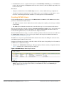
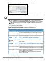
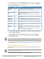
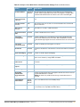
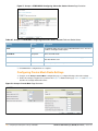
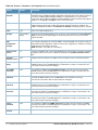
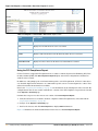
Document Revisions and Enhancements
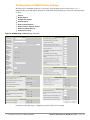
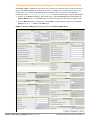
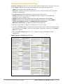
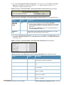
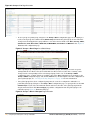
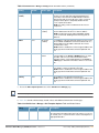
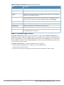
Table 1 summarizes OV3600 product features, graphical user interface (GUI) enhancements, and related document changes.
Table 1 User Guide Document Revisions, OV3600 Version 6.3.0
Enhancement
Document Section
Description
OV3600 Version 6.3
Enhancements
General document
Document consolidates GUI, procedural, and feature-oriented
enhancements, and implements several additional corrections.
For detailed information about the new Alcatel-Lucent Configuration
feature, refer to the new Alcatel-Lucent Configuration Guide.
CDP Device
Discovery
"Discovery of Devices
Overview" on page 144
OV3600 6.3 can discover CDP neighbors of an AP device when the IP
address for that device is known.
General Device
Discovery
Chapter 5, “Discovering,
Adding, and Managing
Devices” on page 143
Updated the chapter to support changes in OV3600 6.3.
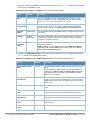
Exporting Reports
to XML
"Exporting Reports to XML" on
page 292
Revised the procedure to account for changes in more recent versions of
MS Excel.
Rogue Device
Classification and
RAPIDS Rules
"Using RAPIDS and Rogue
Classification" on page 201
OV3600 6.3 introduces significant enhancements to the RAPIDS module,
to include changes in classification of rogue devices and introduction of
RAPIDS rules that define rogue classification.
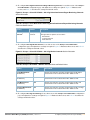
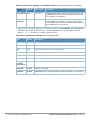
Downgrade
Advisory
Chapter 2, “Installing The
OmniVista 3600 Air Manager
(OV3600)”
Downgrade from Version 6.3 may result in data loss and other risks. Refer
to Chapter 2, “Installing The OmniVista 3600 Air Manager (OV3600)” .
“OV3600 Setup”
and general
configuration
Chapter 3, “Configuring the
OmniVista Air Manager
(OV3600)” on page 37
Cisco WLSE
"Configuring Cisco WLSE and
WLSE Rogue Scanning" on
page 61
Overhauled topics to describe enhancements in the OV3600 Setup
section through OV3600 Version 6.3.
Moved information about the OV3600 Setup > PCI Compliance
instructions to this chapter.
Moved initial device configuration information to this chapter.
Consolidated topics supporting Cisco WLSE in OV3600.
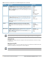
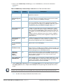
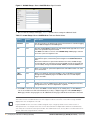
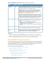
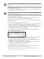
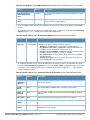
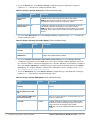
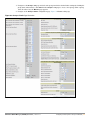
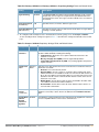
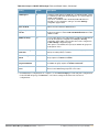
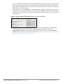
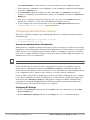
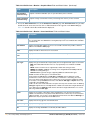
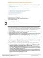
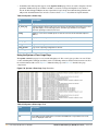
Table 2 summarizes content changes to this document after initial release of OV3600 Version 6.3.x. These changes are of the following
types:
enhancements to information in support of OV3600 6.3 features
features from earlier OV3600 versions that were not described at the time of their original availability
revisions to product or document bugs between major feature releases
revisions derived from customer feedback or alternate sources
Table 2 User Guide Document Revisions, OV3600 Version 6.3.x
Enhancement or Change
Document Section
Alcatel-Lucent Configuration
information
"Alcatel-Lucent
Configuration" on page 17
Chapter cites additional AOS-W information in support of the
Alcatel-Lucent Configuration feature.
Reports in O V3600
"Creating, Running, and
Emailing Reports" on
page 263
Chapter “Introduction” cites three additional and lesser-known
report options that are separate from the Reports pages in
OV3600.
Users > Guest Users page
"Configuring Your Own User
Information with the Home >
User Info Page" on page 246
Topic cites additional information about using this page.
2 | Copyright
Description
OmniVista 3600 Air Manager (OV3600) User Guide | Version 6.3
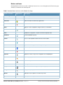
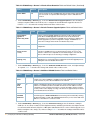
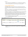
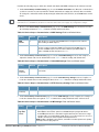
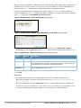
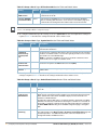
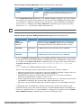
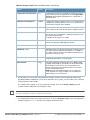
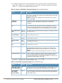
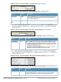
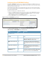
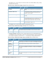
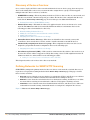
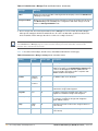
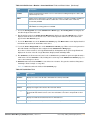
Table 2 User Guide Document Revisions, OV3600 Version 6.3.x (Continued)
Enhancement or Change
Document Section
Users > Tags page
"Supporting Users on Thin AP
Networks With the Users >
Tags Page" on page 240
Topic cites additional information about RFID tags.
Web Auth Bundle information
supporting Cisco WLAN
switches
"Using Web Auth Bundles in
OV3600" on page 56
Chapter adds a new procedure to support the Web Auth
Bundle feature on the Device Setup > Upload Files page.
Authentication Type
"Using the OV3600 APs/
Devices Pages for AP
Communication Settings" on
page 172 (Table 124)
Increased certain details about authentication types reported
in OV3600.
Backing Up OV3600
"Backing Up OV3600" on
page 258
Updated graphics and information for backups of OV3600
Version 6.3.2 and later OV3600 versions.
OmniVista 3600 Air Manager (OV3600) User Guide | Version 6.3
Description
Document Revisions and Enhancements | 3
4 | Document Revisions and Enhancements
OmniVista 3600 Air Manager (OV3600) User Guide | Version 6.3
Contents
Contents
Preface
Chapter 1
Chapter 2
Chapter 3
11
Document Organization
11
Text Conventions
12
Contacting Alcatel-Lucent
13
Introduction to the OmniVista Air Manager 3600 (OV3600)
15
OV3600—A Unified Wireless Network Command Center
15
VisualRF™
16
RAPIDs™
16
Alcatel-Lucent Configuration
17
Master Console and Failover
17
Integrating OV3600 into the Network and Organizational Hierarchy
17
Installing The OmniVista 3600 Air Manager (OV3600)
21
Introduction
21
OV3600 Hardware Requirements and Installation Media
21
Installing Linux CentOS 5 (Phase 1)
22
Installing OV3600 Software (Phase 2)
Getting Started
Step 1: Configuring Date and Time, Checking for Prior Installations
Date and Time
Previous OV3600 Installations
Step 2: Installing OV3600 Software, Including OV3600
Step 3: Checking the OV3600 Installation
Step 4: Assigning an IP Address to the OV3600 System
Step 5: Naming the OV3600 Network Administration System
Step 6: Assigning a Host Name to the OV3600
Step 7: Changing the Default Root Password
Completing the Installation
23
23
23
23
23
24
24
24
25
25
25
26
Configuring and Mapping Port Usage for OV3600 Version 6.3
27
OV3600 Navigation Basics
Status Section
Navigation Section
Activity Section
Help Links in the GUI
Buttons and Icons
28
29
30
32
32
33
Getting Started with OV3600
Completing Initial Login
35
35
Configuring the OmniVista Air Manager (OV3600)
37
Introduction
37
Defining General OV3600 Server Settings
38
Defining OV3600 Network Settings
43
Creating OV3600 Users
45
Creating OV3600 User Roles
47
Enabling OV3600 to Manage Your Devices
49
OmniVista 3600 Air Manager (OV3600) User Guide | Version 6.3
Contents | 5
Configuring Communication Settings for Discovered Devices
Loading Device Firmware onto OV3600
Overview of the Device Setup > Upload Files Page
Loading Firmware Files to OV3600 6.3
Using Web Auth Bundles in OV3600
Chapter 4
6 | Contents
50
53
53
54
56
Configuring TACACS+ and RADIUS Authentication
Configuring TACACS+ Authentication
Configuring RADIUS Authentication and Authorization
Integrating a RADIUS Accounting Server
57
57
59
59
Configuring Cisco WLSE and WLSE Rogue Scanning
Introduction to Cisco WLSE
Configuring WLSE Initially in OV3600
Adding an ACS Server for WLSE
Enabling Rogue Alerts for Cisco WLSE
Configuring WLSE to Communicate with APs
Discovering Devices
Managing Devices
Inventory Reporting
Defining Access
Grouping
Configuring IOS APs for WDS Participation
WDS Participation
Primary or Secondary WDS
Configuring ACS for WDS Authentication
Configuring Cisco WLSE Rogue Scanning
61
61
61
62
62
62
62
62
63
63
63
63
63
63
64
64
Configuring ACS Servers
66
Integrating OV3600 with an Existing Network Management Solution (NMS)
67
Auditing PCI Compliance on the Network
Introduction to PCI Requirements
Overview of PCI Auditing in OV3600 6.3
PCI Auditing in the OV3600 Interface
Enabling or Disabling PCI Auditing
69
69
70
70
72
Deploying WMS Offload
Overview of WMS Offload in OV3600
General Configuration Tasks Supporting WMS Offload in OV3600
Additional Information Supporting WMS Offload
73
73
73
74
Configuring and Using Device Groups in OV3600
75
Introduction
75
OV3600 Group Overview
Important Group Concepts
Viewing All Defined Device Groups
Searching in Groups
76
76
77
78
Configuring Basic Group Settings for the Access Points Group
What Next?
79
85
Configuring Group Security Settings
86
Configuring Group SSIDs and VLANs
91
Adding and Configuring Group AAA Servers
96
Configuring Group Radio Settings
98
Configuring Cisco WLC Radio Settings
Configuring Global Controller Settings
106
106
Configuring LWAPP AP Settings
124
Configuring Group PTMP/WiMAX Settings
126
Configuring Proxim Mesh Radio Settings
130
OmniVista 3600 Air Manager (OV3600) User Guide | Version 6.3
Chapter 5
Chapter 6
Configuring Colubris Advanced Settings
132
Configuring Group MAC Access Control Lists
134
Specifying Minimum Firmware Versions for APs in a Group
135
Creating New Groups
136
Deleting a Group
136
Changing Multiple Group Configurations
136
Modifying Multiple Devices
137
Using Global Groups for Group Configuration
139
Discovering, Adding, and Managing Devices
143
Introduction
143
Discovery of Devices Overview
144
Defining Networks for SNMP/HTTP Scanning
Adding Networks for SNMP/HTTP Scanning
Defining Credentials for SNMP/HTTP Scanning
Defining a SNMP/HTTP Scan Set
Executing a Scan by Running a Scan Set
144
145
146
147
148
Manually Adding Individual Devices
Adding Devices with the Device Setup > Add Page
150
150
Adding Access Points, Routers and Switches with a CSV File
153
Adding Universal Devices
154
Assigning Newly Discovered Devices to Groups
Overview
Adding a Newly Discovered Device to a Group
Verifying That Devices Are Added to a Group
155
155
156
156
Troubleshooting a Newly Discovered Device with Down Status
160
Replacing a Broken Device
162
Verifying the Device Configuration Status
Moving a Device from Monitor Only to Manage Read/Write Mode
162
163
Configuring Individual Device Settings
Overview of Individual Device Configuration
Configuring AP Settings
164
164
164
Configuring AP Communication Settings
Using the OV3600 APs/Devices Pages for AP Communication Settings
Using Device Folders (Optional)
Monitoring APs with the Monitoring and Controller Pages
171
172
172
174
Creating and Using Templates
181
Introduction
181
Overview of Group Templates
Supported Device Templates
Template Variables
182
182
182
Viewing and Adding Templates
183
Configuring General Template Files and Variables
Configuring General Templates
Using Template Syntax
Using Directives to Eliminate Reporting of Configuration Mismatches
Using Conditional Variables in Templates
Using Substitution Variables in Templates
Using AP-Specific Variables
187
187
189
189
190
190
191
Configuring Cisco IOS Templates
Applying Startup-config Files
WDS Settings in Templates
192
192
192
OmniVista 3600 Air Manager (OV3600) User Guide | Version 6.3
Contents | 7
SCP Required Settings in Templates
Supporting Multiple Radio Types via a Single IOS Template
Configuring Single and Dual-Radio APs via a Single IOS Template
Chapter 7
Chapter 8
8 | Contents
193
193
193
Configuring Symbol Controller / HP WESM Templates
Configuring Clustering and Redundancy
Changing Redundancy Configuration
Adding Clustering Members
194
196
196
197
Configuring a Global Template
197
Using RAPIDS and Rogue Classification
201
Introduction
201
Overview of RAPIDS
202
Overview of OV3600 Rogue Classification Types
RAPIDS Classification on the RAPIDS > Rules Page
Controller Classification Within WMS Offload
Device OUI Score
Rogue Device Threat Level
203
203
204
204
204
Monitoring Rogue AP Devices
Using the RAPIDS > Overview Page to Monitor Rogue Devices
Using the RAPIDS > Rogue APs Pages to Monitor Rogue Devices
Updating a Rogue Device with the RAPIDS > Rogue APs Page
Viewing Ignored Rogue Devices with the RAPIDS > Rogue APs Page
Using RAPIDS Workflow to Process Rogue Devices
205
205
206
209
210
210
Configuring RAPIDS with the RAPIDS > Setup Page
Using the Basic Configuration Section
Using the Classification Options Section
Using the Filtering Options Section
211
211
212
212
Creating and Using RAPIDS Rules
Viewing and Configuring RAPIDS Rules in OV3600
Examples of RAPIDS Rules
Using RAPIDS Rules with Additional OV3600 Functions
213
213
217
218
Using the RAPIDS OUI Score Override
218
Performing Daily Operations in OV3600
221
Introduction
221
Creating and Using Triggers and Alerts
Overview of Triggers and Alerts
Viewing Triggers
Creating New Triggers
Setting Triggers for Devices
Setting Triggers for Radios
Setting Triggers for Discovery
Setting Triggers for Users
Setting Triggers for RADIUS Authentication Issues
Setting Triggers for IDS Events
Setting Triggers for OV3600 Health
Delivering Triggered Alerts
Viewing Alerts
222
222
222
223
225
227
228
229
231
232
233
233
234
Monitoring and Supporting OV3600 Users with the Users Page
Overview of the Users Pages
Monitoring Connected Users With the Users > Connected Page
Supporting Guest Users With the Users > Guest Users Page
Overview of the Users > Guest Users Page
Supporting Users on Thin AP Networks With the Users > Tags Page
235
235
235
238
238
240
Monitoring and Supporting OV3600 with the Home Pages
Overview of the Home Pages
241
241
OmniVista 3600 Air Manager (OV3600) User Guide | Version 6.3
Chapter 9
Chapter 10
Monitoring OV3600 with the Home > Overview Page
Viewing and Updating License Information with the Home > License Page
Searching OV3600 with the Home > Search Page
Accessing OV3600 Documentation with the Home > Documentation Page
Configuring Your Own User Information with the Home > User Info Page
241
244
245
246
246
Monitoring and Supporting Multiple OV3600 Stations with the Master Console
Adding a Managed OV3600 with the Master Console
248
249
Monitoring and Supporting OV3600 with the System Pages
Using the System > Status Page
Using the System > Event Logs Page
Using the System > Configuration Change Jobs Page
Using the System > Performance Page
253
253
254
255
256
Backing Up OV3600
Overview of Backups
Viewing and Downloading Backups
Running Backup on Demand
Backing Up OV3600 Data
Restoring Data from the Old OV3600 to the New OV3600 Server
OV3600 Failover
Navigation Section of OV3600 Failover
Adding Watched OV3600 Stations
258
258
258
259
259
259
259
260
260
Creating, Running, and Emailing Reports
263
Introduction
263
Overview of OV3600 6.3 Reports
Supported Report Types in OV3600 6.3
Reports > Definitions Page Overview
Reports > Generated Page Overview
263
264
265
266
Using Daily Reports in OV3600 6.3
Viewing Generated Reports
Using the Capacity Planning Report
Using the Configuration Audit Report
Using the Device Summary Report
Using the Device Uptime Report
Using the IDS Events Report
Using the Inventory Report
Using the Memory and CPU Utilization Report
Using the Network Usage Report
Using the New Rogue Devices Report
Using the New Users Report
Using the PCI Compliance Report
Defining and Generating PCI Compliance Reports
Using the RADIUS Authentication Issues Report
Using the User Session Report
267
267
268
269
271
273
275
276
277
278
279
281
282
283
285
286
Creating and Running Custom Reports
289
Emailing and Exporting Reports
Emailing Reports in General Email Applications
Emailing Reports to Smarthost
Exporting Reports to XML
292
292
292
292
Using the OV3600 Helpdesk
293
Introduction
293
OV3600 Helpdesk Overview
293
Monitoring Incidents with Helpdesk
294
Creating a New Incident with Helpdesk
295
Creating New Snapshots or Incident Relationships
296
OmniVista 3600 Air Manager (OV3600) User Guide | Version 6.3
Contents | 9
Appendix A
Appendix B
Appendix C
Appendix D
Appendix E
Appendix F
Appendix G
Appendix H
Index
10 | Contents
Using the Helpdesk Tab with an Existing Remedy Server
297
Package Management for OV3600 Version 6.3
301
Yum for OV3600 6.3
301
Package Management System Advisories for OV3600 6.3
301
Third-Party Security Integration for OV3600
303
Introduction
303
Bluesocket Integration
Requirements
Bluesocket Configuration
303
303
303
ReefEdge Integration
Requirements
ReefEdge Configuration
304
304
304
HP ProCurve 700wl Series Secure Access Controllers Integration
Requirements
Example Network Configuration
HP ProCurve 700wl Series Configuration
305
305
305
306
Access Point Notes
307
Resetting Cisco (VxWorks) Access Points
Introduction
Connecting to the AP
Determining the Boot-Block Version
Resetting the AP (for Boot-Block Versions from 1.02 to 11.06)
Resetting the AP (for Boot-Block Versions 11.07 and Higher)
307
307
307
307
308
308
IOS Dual Radio Template
309
Speed Issues Related to IOS Firmware Upgrades
OV3600 Firmware Upgrade Process
310
310
Initiating a Support Connection
311
Network Requirements
311
Procedure
311
Cisco Clean Access Integration (Perfigo)
313
Requirements
313
Adding OV3600 as RADIUS Accounting Server
313
Configuring Data in Accounting Packets
313
HP Insight Install Instructions for OV3600 Servers
315
Installing OV3600 6.3 on VMware ESX (3i v. 3.5)
317
Creating a New Virtual Machine to Run OV3600
317
Installing OV3600 on the Virtual Machine
317
OV3600 Post-Installation Issues on VMware
318
Third-Party Copyright Information
319
Copyright Notices
Packages
Net::IP:
Net-SNMP:
Crypt::DES perl module (used by Net::SNMP):
Perl-Net-IP:
Berkeley DB 1.85:
SWFObject v. 1.5:
mod_auth_tacacs - TACACS+ authentication module:
319
319
319
319
322
323
324
324
324
327
OmniVista 3600 Air Manager (OV3600) User Guide | Version 6.3
Preface
This preface provides an overview of this document, a list of general documentation supporting OV3600 Version 6.3, and
contact information for Alcatel-Lucent Wireless with the following sections:
Document Organization
Text Conventions
Contacting Alcatel-Lucent
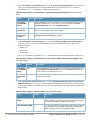
Document Organization
This user guide includes instructions and examples of the graphical user interface (GUI) for installation, configuration, and
daily operation of the OmniVista 3600 Air Manager (OV3600), Version 6.3. This includes wide deployment of wireless access
points (APs), device administration, rogue detection and classification, wireless WLAN switch devices, security, reports, and
additional features of OV3600 6.3.
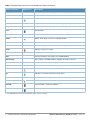
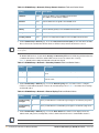
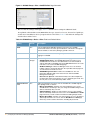
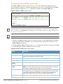
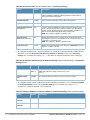
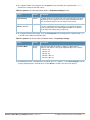
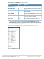
Table 3 Document Organization and Purposes
Chapter
Description
Chapter 1, “Introduction to the OmniVista Air
Manager 3600 (OV3600)”
Introduces and presents the OmniVista 3600 Air Manager (OV3600), Version 6.3,
OV3600 components, and general network functions.
Chapter 2, “Installing The OmniVista 3600 Air
Manager (OV3600)”
Describes system and network requirements, Linux OS installation, and OV3600
installation.
Chapter 3, “Configuring the OmniVista Air
Manager (OV3600)”
Describes the primary and required configurations for startup and launch of OV3600
6.3, with frequently used optional configurations.
Chapter 4, “Configuring and Using Device
Groups in OV3600”
Describes configuration and deployment for group device profiles.
Chapter 5, “Discovering, Adding, and Managing
Devices”
Describes how to discover and manage devices on the network.
Chapter 6, “Creating and Using Templates”
Describes and illustrates the use of templates in group and global device
configuration.
Chapter 7, “Using RAPIDS and Rogue
Classification”
Describes the RAPIDS module of OV3600, and enhanced rogue classification
supported in OV3600 6.3.
Chapter 8, “Performing Daily Operations in
OV3600”
Describes common daily operations and tools in OV3600 6.3, to include general
user administration, the use of triggers and alerts, network monitoring, and
backups.
Chapter 9, “Creating, Running, and Emailing
Reports”
Describes OV3600 reports, scheduling and generation options, and distribution of
reports from OV3600 6.3.
Chapter 10, “Using the OV3600 Helpdesk”
Describes how to use the OV3600 6.3 Helpdesk GUI and related functions.
Appendix A, “Package Management for
OV3600 Version 6.3”
Describes the Yum packaging management system, and provides advisories on
alternative methods that may cause issues with OV3600.
OmniVista 3600 Air Manager (OV3600) User Guide | Version 6.3
Preface | 11
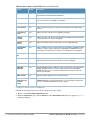
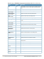
Table 3 Document Organization and Purposes
Chapter
Description
Appendix B, “Third-Party Security Integration
for OV3600”
Describes additional and optional security configurations in OV3600 Version 6.3.
Appendix C, “Access Point Notes”
Provides guidelines and suggestions for Access Point devices in OV3600.
Appendix D, “Initiating a Support Connection”
Provides instructions about how to create and use a support connection between
OV3600 and Alcatel-Lucent Enterprise Service & Support.
Appendix E, “Cisco Clean Access Integration
(Perfigo)”
Provides instructions for integrating Cisco Clean Access within OV3600.
Appendix F, “HP Insight Install Instructions for
OV3600 Servers”
Provides instructions for installing HP Insight on OV3600 6.3 servers.
Appendix G, “Installing OV3600 6.3 on VMware
ESX (3i v. 3.5)”
Provides instructions for an alternative installation option on VMware ESX for
OV3600 Version 6.3.
Appendix H, “Third-Party Copyright Information” Presents multiple copyright statements from multiple equipment vendors that
interoperate with OV3600 Version 6.3.
Index
Provides extensive citation of and links to document topics, with emphasis on the
OV3600 6.3 GUI and tasks relating to OV3600 6.3 installation and operation.
Text Conventions
The following conventions are used throughout this manual to emphasize important concepts:
Table 4 Text Conventions
Type Style
Description
Italics
This style is used to emphasize important terms and to mark the titles of books.
System items
This fixed-width font depicts the following:
Sample screen output
System prompts
Filenames, software devices, and specific commands when mentioned in the text
Commands
In the command examples, this bold font depicts text that you must type exactly as shown.
<Arguments>
In the command examples, italicized text within angle brackets represents items that you should
replace with information appropriate to your specific situation. For example:
# send <text message>
In this example, you would type “send” at the system prompt exactly as shown, followed by the
text of the message you wish to send. Do not type the angle brackets.
[Optional]
In the command examples, items enclosed in brackets are optional. Do not type the brackets.
{Item A | Item B}
In the command examples, items within curled braces and separated by a vertical bar represent
the available choices. Enter only one choice. Do not type the braces or bars.
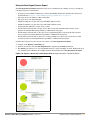
This document uses the following notice icons to emphasize advisories for certain actions, configurations, or concepts:
12 | Preface
OmniVista 3600 Air Manager (OV3600) User Guide | Version 6.3
Indicates helpful suggestions, pertinent information, and important things to remember.
NOTE
!
Indicates a risk of damage to your hardware or loss of data.
CAUTION
Indicates a risk of personal injury or death.
WARNING
Contacting Alcatel-Lucent
Online Contact and Support
Main Website
http://www.alcatel-lucent.com/enterprise
Support Website
https://service.esd.alcatel-lucent.com
Alcatel-Lucent Enterprise Service and OmniVista
3600 Email Support
[email protected]
OmniVista 3600 Air Manager (OV3600) User Guide | Version 6.3
Preface | 13
14 | Preface
OmniVista 3600 Air Manager (OV3600) User Guide | Version 6.3
Chapter 1
Introduction to the OmniVista
Air Manager 3600 (OV3600)
Thank you for choosing the OmniVista Air Manager 3600 (OV3600) as the centerpiece of wireless network
management. OV3600 makes it easy and efficient to manage your wireless network by combining industryleading functionality with an intuitive user interface, enabling network administrators and helpdesk staff to
support and control even the largest wireless networks in the world.
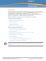
This User Guide provides instructions for the installation, configuration, and operation of the OmniVista Air
Manager 3600 (OV3600). This chapter contains the following topics:
OV3600—A Unified Wireless Network Command Center
VisualRF™
RAPIDs™
Alcatel-Lucent Configuration
Master Console and Failover
Integrating OV3600 into the Network and Organizational Hierarchy
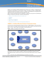
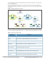
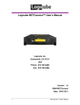
OV3600—A Unified Wireless Network Command Center
OV3600 is the only network management software that offers you a single intelligent console from which to
monitor, analyze, and configure wireless networks in automatic fashion. Whether your wireless network is
simple or a large, complex, multi-vendor installation, OV3600 manages it all.
Figure 1 OV3600—Your Wireless Command Center
The OmniVista Air Manager 3600 (OV3600) supports hardware from leading wireless vendors, including
Alcatel-Lucent, Avaya, Cisco (Aironet and WLC), Colubris Networks, Enterasys, Juniper Networks,
LANCOM Systems, Meru, Nomadix, Nortel, ProCurve by HP, Proxim, Symbol, Trapeze, Tropos, and many
others.
The core components of the OmniVista Air Manager 3600 (OV3600) are as follows:
OmniVista 3600 Air Manager (OV3600) User Guide | Version 6.3
Introduction to the OmniVista Air Manager 3600 (OV3600) | 15
OV3600 wireless network management software
VisualRF location and RF mapping software module
RAPIDS rogue access point detection software module
Alcatel-Lucent Configuration supporting AOS-W and OmniAccess WLAN switches
OV3600 Master Console and Failover Servers for scalability and high-availability
The OV3600 module is the centerpiece of the OV3600 (OV3600) wireless network management solution,
offering the following functions and benefits:
Core network management functionality:
Network discovery
Configuration of APs & WLAN switches
Automated compliance audits
Firmware distribution
Monitoring of every device and user connected to the wireless network
Real-time and historical trend reports
Granular administrative access
Role-based (for example, Administrator contrasted with Help Desk)
Network segment (for example, "Retail Store" network contrasted with "Corporate HQ" network)
Flexible device support
Thin, thick, mesh and WiMAX network architecture
Multi-vendor support
Current and legacy hardware support
VisualRF™
VisualRF is a powerful tool for monitoring and managing Radio Frequency (RF) dynamics within your
wireless network, to include the following functions and benefits:
Accurate location information for all wireless users and devices
Up-to-date heat maps and channel maps for RF diagnostics
Adjusts for building materials.
Supports multiple antenna types.
3-D campus and building views
Visual display of errors and alerts
Easy import of existing floor plans and building maps
RAPIDs™
RAPIDS is a powerful and easy-to-use tool for monitoring and managing security on your wireless network,
to include the following features and benefits:
Automatic detection of unauthorized wireless devices
Rogue classification to include up to four ways in which to classify and process rogue devices
Wireless detection:
Uses authorized wireless APs to report other devices within range.
Calculates and displays rogue location on VisualRF map.
16 | Introduction to the OmniVista Air Manager 3600 (OV3600)
OmniVista 3600 Air Manager (OV3600) User Guide | Version 6.3
Wired network detection:
Discovers Rogue APs located beyond the range of authorized APs/sensors.
Queries routers and switches.
Ranks devices according to the likelihood they are rogues.
Multiple tests to eliminate false positive results.
Provides rogue switch port.
Alcatel-Lucent Configuration
AOS-W is the operating system, software suite, and application engine that operates OmniAccess WLAN
switches and centralizes control over the entire mobile environment. The AOS-W Wizards, the AOS-W
command-line interface (CLI), and the AOS-W WebUI have been the primary means by which to configure
and deploy AOS-W. For a complete description of AOS-W, refer to the AOS-W User Guide.
Commencing with the OmniVista Air Manager 3600 (OV3600) Version 6.3, OV3600 introduces the AlcatelLucent Configuration feature, consolidating AOS-W configuration and pushing global Alcatel-Lucent
Configurations from within OV3600. Two new pages introduced in OV3600 Version 6.3 support Alcatel-Lucent
Configuration:
Device Setup > Alcatel-Lucent Configuration
Groups > Alcatel-lucent Config
OV3600 also introduces new settings and functionality to additional pages in support of Alcatel-Lucent
Configuration.
For additional information that includes a comprehensive inventory of all pages and settings that support
Alcatel-Lucent Configuration, refer to the new Alcatel-Lucent Configuration Guide.
Master Console and Failover
The OV3600 Master Console and Failover tools enable network-wide information in easy-to-understand
presentation, to entail operational information and high-availability for failover scenarios. The benefits of
these tools include the following:
Provides network-wide visibility, even when the WLAN grows to 25,000+ devices.
Executive Portal allows executives to view high-level usage and performance data
Aggregated Alerts
Failover
Many-to-one failover
One-to-one failover
The Master Console and Failover servers can now be configured with a Device Down trigger that
generates an alert if communication is lost to a managed or watched OV3600 station. In addition to
generating an alert, the Master Console or Failover server can also send email or NMS notifications about
the event. See “Using Triggers and Alerts” on page 232.
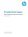
Integrating OV3600 into the Network and Organizational
Hierarchy
OV3600 generally resides in the NOC and communicates with various components of your WLAN
infrastructure. In basic deployments, OV3600 communicates solely with indoor wireless access points and
WLAN switches over the wired network. In more complex deployments OV3600 seamlessly integrates and
communicates with authentication servers, accounting servers, TACACS+ servers, routers, switches,
OmniVista 3600 Air Manager (OV3600) User Guide | Version 6.3
Introduction to the OmniVista Air Manager 3600 (OV3600) | 17
network management servers, wireless IDS solutions, help systems, indoor wireless access points, mesh
devices, and WiMAX devices.
OV3600 has the flexibility to manage devices on local networks, remote networks, and networks using
Network Address Translation (NAT). OV3600 communicates over-the-air or over-the-wire utilizing a variety
of protocols.
Figure 2 Integrating OV3600 into the Network
The power, performance, and usability of the OV3600 solution becomes more apparent when considering
the diverse components within a Wireless LAN. Table 1 itemizes such network components, as an example.
Table 1 Components of a Wireless LAN
Component
Description
Autonomous AP
Standalone device which performs radio and authentication functions
Thin AP
Radio-only device coupled with WLAN Switch to perform authentication
WLAN Switch
Used in conjunction with Thin APs to coordinate authentication and roaming
NMS
Network Management Systems and Event Correlation (OpenView, Tivoli, and so forth)
RADIUS Auth.
RADIUS Authentication servers (Funk, FreeRADIUS, ACS, or IAS)
RADIUS Accounting
OV3600 itself serves as a RADIUS accounting client
Wireless Gateways
Provide HTML redirect and/or wireless VPNs
TACACS+
Used to authenticated OV3600 administrative users
Routers/Switches
Provide OV3600 with data for user information and AP and Rogue discovery
Help Desk Systems
Remedy EPICOR
Rogue APs
Unauthorized APs not registered in OV3600' database of managed APs
18 | Introduction to the OmniVista Air Manager 3600 (OV3600)
OmniVista 3600 Air Manager (OV3600) User Guide | Version 6.3
The flexibility of OV3600 enables it to integrate seamlessly into your business hierarchy as well as your
network topology. OV3600 facilitates various administrative roles to match each individual user's role and
responsibility.
Further flexibility and administrative power include the following benefits:
A Help Desk user may be given read-only access to monitoring data without being permitted to make
configuration changes.
A U.S.-based network engineer may be given read-write access to manage device configurations in North
America, but not to control devices in the rest of the world.
A security auditor may be given read-write access to configure security policies across the entire WLAN.
NOC personnel may be give read-only access to monitoring all devices from the Master Console.
Figure 3 illustrates the wide variety of benefits that OV3600 supports within the organization.
Figure 3 Integrating OV3600 into your Corporate Hierarchy
OmniVista 3600 Air Manager (OV3600) User Guide | Version 6.3
Introduction to the OmniVista Air Manager 3600 (OV3600) | 19
20 | Introduction to the OmniVista Air Manager 3600 (OV3600)
OmniVista 3600 Air Manager (OV3600) User Guide | Version 6.3
Chapter 2
Installing The OmniVista 3600
Air Manager (OV3600)
Introduction
This chapter contains information and procedures to install and launch the OmniVista 3600 Air Manager
(OV3600), Version 6.3. This chapter contains the following topics:
OV3600 Hardware Requirements and Installation Media
Installing Linux CentOS 5 (Phase 1)
Installing OV3600 Software (Phase 2)
Step 1: Configuring Date and Time, Checking for Prior Installations
Step 2: Installing OV3600 Software, Including OV3600
Step 3: Checking the OV3600 Installation
Step 4: Assigning an IP Address to the OV3600 System
Step 5: Naming the OV3600 Network Administration System
Step 6: Assigning a Host Name to the OV3600
Step 7: Changing the Default Root Password
Completing the Installation
Configuring and Mapping Port Usage for OV3600 Version 6.3
OV3600 Navigation Basics
Status Section
Navigation Section
Activity Section
Help Links in the GUI
Buttons and Icons
Getting Started with OV3600
NOTE
Completing Initial Login
OV3600 Version 6.3 should not be downgraded to a prior OV3600 version. Significant data would be lost or
compromised in such a downgrade. Generally, Alcatel-Lucent does not support downgrades from OV3600 Version
6.3.
In unusual circumstances involving return to a prior OV3600 version, the recommended approach is to perform a
fresh installation of the prior OV3600 version, then to restore data from a pre-upgrade backup.
OV3600 Hardware Requirements and Installation Media
The OV3600 installation CD includes all software (including the Linux OS) required to complete the
installation of the OmniVista 3600 Air Manager (OV3600). OV3600 supports any hardware that is RedHat
Enterprise Linux 5 certified.
OV3600 hardware requirements vary by version. As additional features are added to OV3600, increased
hardware resources become necessary. For the most recent hardware requirements, download the OV3600
Hardware Sizing Guide from the Home > Documentation page.
OmniVista 3600 Air Manager (OV3600) User Guide | Version 6.3
Installing The OmniVista 3600 Air Manager (OV3600) | 21
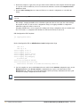
Installing Linux CentOS 5 (Phase 1)
Perform the following steps to install the Linux CentOS 5 operating system. The Linux installation is a
prerequisite to installing OV3600 Version 6.3 on the network management system.
This procedure erases the hard drive(s) on the server.
WARNING
1. Insert the OV3600 installation CD-ROM into the drive and boot the server.
2. If this is a new installation of the OV3600 software, type install and press Enter.
When you press Enter, all existing data on the hard drive is erased.
NOTE
To configure the partitions in manual fashion, type expert and press Enter.
The following message appears on the screen.
Welcome to Alcatel-Lucent OV3600 Installer Phase I
- To install a new Alcatel-Lucent OV3600, type install <ENTER>.
WARNING: This will ERASE all data on your hard drive.
- To install Alcatel-Lucent OV3600 and manually configure hard drive settings, type
expert <ENTER>.
boot:
OV3600 is intended to operate as a soft appliance. Other applications should not run on the same
installation. Additionally, local shell users can access data on OV3600, so it is important to restrict
access to the shell only to authorized users.
1. Allow the installation process to continue in automatic fashion. Installing the CentOS software (Phase I)
takes 10 to 20 minutes to complete. This process formats the hard drive and launches Anaconda to
install all necessary packages. Anaconda gauges the progress of the installation.
Upon completion, the system automatically reboots and ejects the installation CD.
2. Remove the CD from the drive and store in a safe location.
22 | Installing The OmniVista 3600 Air Manager (OV3600)
OmniVista 3600 Air Manager (OV3600) User Guide | Version 6.3
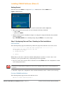
Installing OV3600 Software (Phase 2)
Getting Started
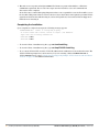
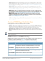
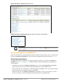
After the reboot, the GRUB screen appears. Figure 4 illustrates the OV3600 GRUB screen.
Figure 4 GRUB Screen
1. Press Enter or wait six seconds, and the system automatically loads the smp kernel.
2. When the kernel is loaded, log into the server using the following credentials:
login = root
password = admin
3. Start the OV3600 software installation script by executing the settings and default values./OV3600install command.
Type ./OV3600-install at the command prompt and press Enter to execute the script.
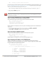
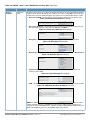
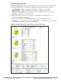
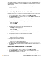
Step 1: Configuring Date and Time, Checking for Prior Installations
Date and Time
The following message appears, and this step ensures the proper date and time are set on the server.
------------------------ Date and Time Configuration -----------------Current Time: Fri June 19 09:18:12 PST 2009
1) Change Date and Time
2) Change Time Zone
0)
Finish
Ensure that you enter the accurate date and time during this process. Errors will arise later in the
installation if the specified date varies significantly from the actual date.
1. Select 1 to set the date and select 2 to set the time zone. Press Enter after each configuration to return
to the message menu above.
WARNING
Changing these settings after the installation can cause a loss of graphical data, and you should avoid delayed
configuration.
2. Press 0 to complete the configuration of date and time information, and to continue to the next step.
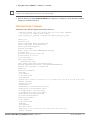
Previous OV3600 Installations
The following message appears after date and time are set.
Welcome to OV3600 Installer Phase 2
OmniVista 3600 Air Manager (OV3600) User Guide | Version 6.3
Installing The OmniVista 3600 Air Manager (OV3600) | 23
STEP 1:
Checking for previous OV3600 installations
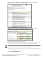
If a previous version of OV3600 software is not discovered, the installation program automatically proceeds
to “Step 2: Installing OV3600 Software, Including OV3600” on page 24. If a previous version of the software
is discovered, the following message appears on the screen.
The installation program discovered a previous version of the software. Would you
like to reinstall OV3600? This will erase OV3600's database. Reinstall (y/n)?
1. Type y and press Enter to proceed.
WARNING
This action erases the current database, including all historical information. To ensure that the OV3600 database is
backed up prior to reinstallation, answer `n` at the prompt above and contact your Value Added Reseller or directly
contact Alcatel-Lucent Support.
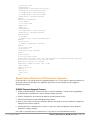
Step 2: Installing OV3600 Software, Including OV3600
The following message appears while OV3600 software is transferred and compiled.
STEP 2: Installing OV3600 software
This will take a few minutes.
Press Alt-F9 to see detailed messages.
Press Alt-F1 return to this screen.
This step requires no user input, but you have the option of monitoring progress in more detail should you
wish to do so:
To view detailed output from the OV3600 software installer, press Alt-F9 or Ctrl-Alt-F9.
Pressing Alt-F1 or Ctrl-Alt-F1 returns you to the main console.
Step 3: Checking the OV3600 Installation
After the OV3600 software installation is complete, the following message appears:
STEP 3: Checking OV3600 installation
Database is up.
OV3600 is running version: (version number)
This step requires no user input. Proceed to the next step as prompted to do so.
Step 4: Assigning an IP Address to the OV3600 System
While the OV3600 primary network interface accepts a DHCP address initially during installation,
OV3600 does not function when launched unless a static IP is assigned. Complete these tasks to assign
the static IP address. The following message appears:
STEP 4: Assigning OV3600's address
OV3600 must be configured with a static IP.
--------------- Primary Network Interface Configuration ------------1)
2)
3)
4)
5)
IP Address
:
Netmask
:
Gateway
:
Primary DNS :
Secondary DNS:
9)
Commit Changes
24 | Installing The OmniVista 3600 Air Manager (OV3600)
xxx.xxx.xxx.xxx
xxx.xxx.xxx.xxx
xxx.xxx.xxx.xxx
xxx.xxx.xxx.xxx
xxx.xxx.xxx.xxx
OmniVista 3600 Air Manager (OV3600) User Guide | Version 6.3
0)
Exit (discard changes)
If you want to configure a second network interface, please
use OV3600's web interface, OV3600 Setup --> Network Tab
1. Enter the network information.
The Secondary DNS setting is an optional field.
NOTE
2. Commit the changes by typing 9 and pressing Enter.
To discard the changes, type 0 and press Enter.
Step 5: Naming the OV3600 Network Administration System
Upon completion of the previous step, the following message appears.
STEP 5: Naming OV3600
OV3600's name is currently set to: New OV3600
Please enter a name for your OV3600:
1. At the prompt, enter a name for your OV3600 server and press Enter.
Step 6: Assigning a Host Name to the OV3600
Upon completion of the previous step, the following message appears on the screen.
STEP 6: Assigning OV3600's hostname
Does OV3600 have a valid DNS name on your network (y/n)?
1. If OV3600 does not have a valid host name on the network, enter `n` at the prompt. The following
message appears:
Generating SSL certificate for < IP Address >
2. If OV3600 does have a valid host name on the network, enter `y` at the prompt. The following message
appears:
Enter OV3600's DNS name:
3. Type the OV3600 DNS name and press Enter. The following message appears:
Generating SSL certificate for < IP Address >
Proceed to the next step as the system prompts you.
Step 7: Changing the Default Root Password
Upon completion of the prior step, the following message appears.
STEP 7: Changing default root password.
You will now change the password for the 'root' shell user.
Changing password for user root.
New Password:
OmniVista 3600 Air Manager (OV3600) User Guide | Version 6.3
Installing The OmniVista 3600 Air Manager (OV3600) | 25
1. Enter the new root password and press Enter. The Linux root password is similar to a Windows
administrator password. The root user is a super user who has full access to all commands and
directories on the computer.
Alcatel-Lucent recommends keeping this password as secure as possible because it allows full access to
the machine. This password is not often needed on a day-to-day basis, but is required to perform OV3600
upgrades and advanced troubleshooting. If you lose this password, contact Alcatel-Lucent Support for
instructions on resetting it.
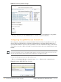
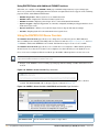
Completing the Installation
Upon completion of all previous steps, the following message appears.
CONGRATULATIONS! OV3600 is configured properly.
To access OV3600 web console, browse to https://<IP Address>
Login with the following credentials:
Username: admin
Password: admin
To view the Phase 1 installation log file, type cat /root/install.log.
To view the Phase 2 installation log file, type cat /tmp/OV3600-install.log.
To access the OV3600 GUI, enter the OV3600 IP address in the address bar of any modern browser. The
OV3600 GUI then prompts for your license key. If you are entering a dedicated Master Console or
OV3600 Failover license, refer to “Monitoring and Supporting Multiple OV3600 Stations with the Master
Console” on page 248 for additional information.
26 | Installing The OmniVista 3600 Air Manager (OV3600)
OmniVista 3600 Air Manager (OV3600) User Guide | Version 6.3
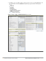
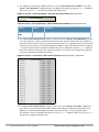
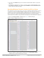
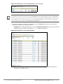
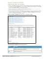
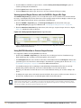
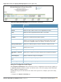
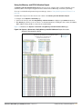
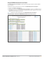
Configuring and Mapping Port Usage for OV3600 Version 6.3
The following diagram itemizes the communication protocols and ports necessary for OV3600 to
communicate with wireless LAN infrastructure devices, including access points (APs), controllers, routers,
switches, and RADIUS servers. Assign or adjust port usage on the network administration system as
required to support these components.
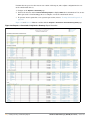
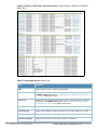
Table 2 OV3600 Protocol and Port Chart
Port
Type
Protocol
Description
Dataflow
Direction
Device Type
21
TCP
FTP
Configure devices and FW distribution
>
Legacy AP (Cisco 4800)
22
TCP
SSH
Configure devices
>
APs or controllers
22
TCP
SSH
Configure OV3600 from CLI
<
Laptop or workstation
22
TCP
VTUN
Support connection (optional)
>
Alcatel-Lucent support home
office
22
TCP
SCP
Transfer configuration files or FW
<
APs or controllers
23
TCP
Telnet
Configure devices
>
APs or controllers
23
TCP
VTUN
Support connection (Optional)
>
Alcatel-Lucent support home
office
25
TCP
SMTP
Support email (optional)
>
Alcatel-Lucent support email
server
49
UDP
TACACS
OV3600 Administrative Authentication
>
Cisco TACACS+
53
UDP
DNS
DNS lookup from OV3600
>
DNS Server
69
UDP
TFTP
Transfer configuration files or FW
<
APs or Controllers
80
TCP
HTTP
Configure devices
>
Legacy APs
80
TCP
HTTP
Firmware upgrades
<
Colubris devices
80
TCP
VTUN
Support connection (optional)
>
Alcatel-Lucent support home
office
161
UDP
SNMP
Get and Set operations
>
APs or controllers
162
UDP
SNMP
Traps from devices
<
APs or controllers
162
UDP
SNMP
Traps from OV3600
>
NMS
192
UDP
OSU
Discovery probe
<
Proxim
443
TCP
HTTPS
Web management
<
Laptop or workstation
443
TCP
VTUN
Support connection (optional)
>
Alcatel-Lucent support home
office
1701
TCP
HTTPS
AP and rogue discovery
>
WLSE
1813
UDP
RADIUS
Retrieve client authentication info
<
Accounting Server
1813
UDP
RADIUS
Retrieve client authentication info
<
AP or Controllers
2002
TCP
HTTPS
Retrieve client authentication info
>
ACS
2719
UDP
OSU
Discovery probe
<
Proxim
5050
UDP
RTLS
Real Time Location Feed
<
Alcatel-Lucent thin APs
8211
UDP
PAPI
Real Time Feed
<>
OmniAccess WLAN Switches
OmniVista 3600 Air Manager (OV3600) User Guide | Version 6.3
Installing The OmniVista 3600 Air Manager (OV3600) | 27
Table 2 OV3600 Protocol and Port Chart (Continued)
Port
Type
Protocol
Description
Dataflow
Direction
Device Type
ICMP
Ping Probe
>
APs or controllers
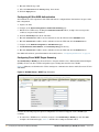
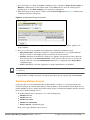
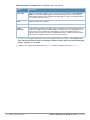
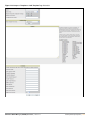
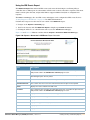
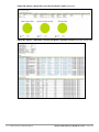
OV3600 Navigation Basics
Every OV3600 page contains three basic sections, as follows:
Status Section
Navigation Section
Activity Section
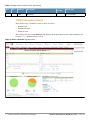
The OV3600 pages also contain Help links with GUI-specific help information and certain standard action
buttons. Figure 5 illustrates these sections.
Figure 5 Home > Overview Page Illustration
28 | Installing The OmniVista 3600 Air Manager (OV3600)
OmniVista 3600 Air Manager (OV3600) User Guide | Version 6.3
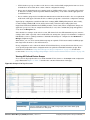
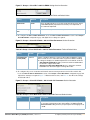
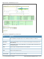
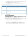
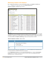
Status Section
The Status Section provides a snapshot view of overall WLAN performance and provides direct links for
immediate access to key system components. The table below describes these elements in further detail.
Table 3 Status Section Components of the OV3600 Graphical User Interface (GUI)
Field
Description
New Devices
The number of wireless APs or wireless LAN switches/controllers that have been discovered by
OV3600 but not yet managed by network administrators. When you click this link, OV3600 directs
you to a page that displays a detailed list of devices awaiting authorization.
Up
The number of managed, authorized devices that are currently responding to OV3600 requests.
When you click this link, OV3600 will direct you to a page that displays a detailed list of all Up
devices.
Down
The number of managed, authorized devices that are not currently responding to OV3600 SNMP
requests. When you click this link, OV3600 will direct you to a page that displays a detailed list of
all "Down" devices.
Mismatched
The total number of Mismatched APs. An AP is considered mismatched when the desired
configuration in OV3600 does not match the actual device configuration read off of the AP.
Rogue
The number of unknown APs detected on the network by OV3600 with a score of five. A score of
five means the rogues were discovered via wireless or wireline fingerprint scanning techniques.
When you click this link, OV3600 will direct you to a page that displays a detailed list of all Rogue
APs.
NOTE: A newly discovered AP is considered a "Rogue" if it is not a supported AP that OV3600
can manage and monitor. If the newly discovered AP is capable of being managed and monitored
by OV3600 it will be classified as a "New" device rather than a "Rogue."
Users
The number of wireless users currently associated to the wireless network via all the APs
managed by OV3600. When you click this link, OV3600 directs you to a page that contains a list
of users that are associated.
Alerts
Displays the number of non-acknowledged OV3600 alerts generated by user-configured triggers.
When you click this link, OV3600 directs you to a page containing a detailed list of active alerts.
Severe Alerts
(conditional)
When triggers are given a severity of Critical, they generate Severe Alerts. When a Severe Alert
exists, a new component appears at the right of the Status field in bold red font. Only users
configured on the Home > User Info page to be enabled to view critical alerts can see Severe
Alerts. The functionality of Severe Alerts is the same as that described above for Alerts. However,
unlike Alerts, the Severe Alerts section is hidden if there are no Severe Alerts.
Search
Search performs partial string searches on a large number of fields including the notes, version,
secondary version, radio serial number, device serial number, LAN MAC, radio MAC and apparent
IP of all the APs as well as the client MAC, VPN user, LAN IP, VPN IP fields.
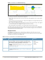
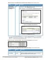
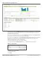
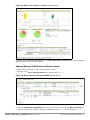
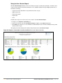
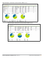
Many of the graphs in OV3600 are flash-based, which allows you change graph attributes.
OmniVista 3600 Air Manager (OV3600) User Guide | Version 6.3
Installing The OmniVista 3600 Air Manager (OV3600) | 29
Figure 6 Flash Graphs on the Home Overview Page
This flash-enabled GUI allows for custom settings and adjustments, and the following examples illustrate
some changes you can make or functions that are supported:
Drag the slider at the bottom of the screen to move the scope of the graph between one year ago and the
current time.
Deselect (remove the check for) the boxes to change the data displayed on each graph. The button with
green arrows refreshes data on the graph.
Once a change to the slider bars or to the display boxes has been made, the same change can be applied
to all other flash graphs with an apply button (appears on mouse-over only).
For non-flash graphs, click the graph to open a popup window that shows historical data.
A non-flash version of the OV3600 user page is available if desired; instead of flash it uses the RRD graphs
that were used in OV3600 through the 5.3 Version. Contact Alcatel-Lucent support for more information on
activating this feature in the OV3600 database.
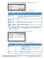
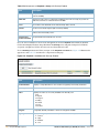
Navigation Section
The Navigation Section displays tabs to all main GUI pages within the OV3600. The top bar is a static
navigation bar containing tabs for the main components of OV3600, while the lower bar is context-sensitive
and displays the sub-menus for the highlighted tab.
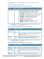
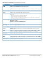
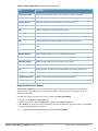
Table 4 Components and Sub-Menus of the OV3600 Navigation Screen
Main Tab
Description
Sub-Menus
Home
The Home page provides basic OV3600 information including system name,
host name, IP address, current time, running time, and software version.
The Home page also provides a central point for network status information
and monitoring tools, giving graphical display of network activity.
The Home > Overview page provides links to many of the most frequent tools
in OV3600.
For additional information, refer to “Monitoring and Supporting OV3600 with
the Home Pages” on page 241.
The Helpdesk page provides an interface for support and diagnostic tools.
For additional information refer to Chapter 10, “Using the OV3600 Helpdesk”
on page 293.
Helpdesk
30 | Installing The OmniVista 3600 Air Manager (OV3600)
Overview
Search
Documentation
License
User Info
Incidents
Setup
OmniVista 3600 Air Manager (OV3600) User Guide | Version 6.3
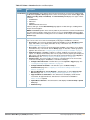
Table 4 Components and Sub-Menus of the OV3600 Navigation Screen (Continued)
Main Tab
Description
Sub-Menus
Groups
The Groups page provides information on the logical "groups" of devices that
have been established for efficient monitoring and configuration. For additional
information, see Chapter 4, “Configuring and Using Device Groups in OV3600”
on page 75.
NOTE: Some of the tabs will not appear for all groups. Tabs are visible based
on the device type field on the Groups > Basic page.
NOTE: When specified, device-level settings override the default Group-level
settings.
The APs/Devices page provides detailed information about all authorized APs
and wireless LAN switches or controllers on the network, including all
configuration and current monitoring data.
This page interacts with several additional pages in OV3600. One chapter to
emphasize the APs/Devices page is Chapter 5, “Discovering, Adding, and
Managing Devices” on page 143.
NOTE: When specified, device-level settings override the default Group-level
settings.
The Users page provides detailed information about all client devices and
users currently associated to the WLAN. For additional information, refer to
“Monitoring and Supporting OV3600 Users with the Users Page” on page 235.
APs/Devices
Users
Reports
System
The Reports page lists all the standard and custom reports generated by
OV3600. OV3600 Version 6.3 supports 13 reports in the OV3600 module. For
additional information, refer to Chapter 9, “Creating, Running, and Emailing
Reports” on page 263.
The System page provides information about OV3600 operation and
administration, including overall system status, the job scheduler, trigger/alert
administration, and so forth. For additional information, refer to “Monitoring
and Supporting OV3600 with the System Pages” on page 253.
Device Setup
The Device Setup page provides information related to the configurations of
devices on the WLANs, including AP discovery parameters, firmware
management, VLAN definition, and so forth. For additional information, refer to
“Enabling OV3600 to Manage Your Devices” on page 49.
OmniVista 3600 Air Manager (OV3600) User Guide | Version 6.3
List
Focused Sub-Menus
Monitor
Basic
Templates
Security
SSIDs
AAA Servers
Radio
Cisco WLC Radio
LWAPP APs
WiMAX
Proxim Mesh
Colubris
MAC ACL
Firmware
List
New
Up
Down
Mismatched
Ignored
Focused Sub-Menus
Manage
Audit
Compliance
Connected
All
Guest Users
Tags
User Detail
Generated
Definition
Focused Sub-Menus
Details
Status
Event Log
Triggers
Alerts
Configuration Change Jobs
Firmware Upgrade Jobs
Performance
Discover
Add
Communication
Upload Files
Installing The OmniVista 3600 Air Manager (OV3600) | 31
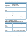
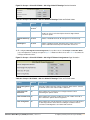
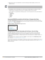
Table 4 Components and Sub-Menus of the OV3600 Navigation Screen (Continued)
Main Tab
Description
Sub-Menus
OV3600 Setup
The OV3600 Setup page provides all information relating to the configuration
of OV3600 itself and its connection to your network. This page entails several
processes, configurations, or tools in OV3600. For additional information, start
with Chapter 3, “Configuring the OmniVista Air Manager (OV3600)” on page 37.
NOTE: The OV3600 Setup page may not be visible, depending on the role and
license set in OV3600.
RAPIDS
VisualRF
The RAPIDS page provides all information relating to rogue access points.
Including methods of discovery and lists of discovered and possible rogues.
For additional information, refer to “Reports—The New Rogue Devices Report
displays summary and detail information about all rogues first discovered in a
given time period. For more information, refer to “Creating, Running, and
Emailing Reports” on page 269.” on page 202.
NOTE: The RAPIDS page may not be visible, depending on the role and license
set in OV3600.
VisualRF pages provide access to floor plans, client location, and RF
visualization. For additional information, refer to the VisualRF User Guide.
NOTE: VisualRF may not be visible, depending on the role and license set in
OV3600.
Master Console
NOTE
The Master Console page provides a centralized location to manage multiple
OV3600s. For additional information, refer to “Monitoring and Supporting
Multiple OV3600 Stations with the Master Console” on page 248.
NOTE: The Master Console page may not be visible, depending on the role
and license set in OV3600.
General
Network
Users
Roles
Authentication
WLSE
ACS
NMS
RADIUS Accounting
PCI Compliance
Overview
Rogue APs
Setup
Score Override
Overview
Floor Plans
Campus/Building
Setup
Import
Overview
Managed OV3600s
Alerts
Search
The OV3600 Setup tab varies based on your or the user’s role. The Master Console, RAPIDS and VisualRF tabs
appear based on the license entered on the Home License page, and might not be visible on your OV3600 view.
Activity Section
The Activity section displays all detailed configuration and monitoring information, and is where changes
are implemented.
Help Links in the GUI
The Help link is available on every page within OV3600. When clicked, this launches a PDF document with
information describing the OV3600 page that is currently displayed.
Adobe Reader must be installed to view the settings and default values in the PDF help file.
NOTE
32 | Installing The OmniVista 3600 Air Manager (OV3600)
OmniVista 3600 Air Manager (OV3600) User Guide | Version 6.3
Buttons and Icons
Standard buttons and icons are used consistently from screen to screen throughout the OV3600 user pages
and GUI, as itemized in the following table:
Table 5 Standard Buttons and Icons of the OV3600 User Page
Buttons and Icons
Appearancea
Description
Acknowledge
Acknowledge and clear an OV3600 alert.
Add
Add the object to both OV3600' database and the onscreen display list.
Add Folder
Add a new folder to hierarchically organize APs.
Alert
Indicates an alert.
Apply
Apply all "saved" configuration changes to devices on the WLAN.
Attach
Attach a snapshot of an OV3600 screen to a Helpdesk incident.
Audit
Read device configuration, compare to desired, and update status.
Bandwidth
Current bandwidth for group.
Choose
Choose a new Helpdesk incident to be the Current Incident.
Create
Create a new Helpdesk incident.
Customize
Ignore selected settings when calculating the configuration status.
Delete
Delete an object from OV3600' database.
Down
Indicate down devices and radios.
Duplicate
Duplicate or makes a copy of the configuration of an OV3600 object.
Edit
Edit the object properties.
Email
Link to email reports.
Filter
Filter rogue list by score and/or ad hoc status.
Google Earth
View device's location in Google Earth (requires plug-in).
Manage
Manage the object properties.
Monitor
Indicates an access point is in “monitor only" mode.
Ignore
Ignore specific device(s) - devices selected with check boxes.
OmniVista 3600 Air Manager (OV3600) User Guide | Version 6.3
Installing The OmniVista 3600 Air Manager (OV3600) | 33
Table 5 Standard Buttons and Icons of the OV3600 User Page (Continued)
Buttons and Icons
Appearancea
Description
Import
Update a Group's desired settings to match current settings.
Mismatched
Indicates mismatched access points.
New Devices
Indicates new access points and devices.
Poll Now
Poll device (or controller) immediately, override group polling settings.
Preview
Display a preview of changes applicable to multiple groups.
Print
Print the report.
Reboot
Reboot devices or OV3600.
Relate
Relates an AP, Group or Client to a Helpdesk incident.
Replace Hardware
Confers configuration and history of one AP to a replacement device.
Revert
Return all configurable data on the screen to its original status.
Rogue
Indicates a rogue access point.
Run
Run a new user-defined report.
Save
Save the information on the page in the OV3600 database.
Save & Apply
Save changes to OV3600' database and apply all changes to devices.
Scan
Scans for devices and rogues using selected networks.
Schedule
Schedule a window for reports, device changes, or maintenance.
Search
Search OV3600 for the specified name, MAC or IP address.
Up
Indicates access points which are in the up status.
Update Firmware
Apply a new firmware image to an AP/device.
User
Indicates a user.
VisualRF
Link to VisualRF - real time visualization.
XML
Link to export XHTML versions of reports.
a. Not all OV3600 GUI components are itemized in graphic format in this table.
34 | Installing The OmniVista 3600 Air Manager (OV3600)
OmniVista 3600 Air Manager (OV3600) User Guide | Version 6.3
Getting Started with OV3600
This topic describes how to perform an initial launch of the OV3600 network management solution. This
topic requires successful completion of installation, as described earlier in this chapter. This topic prepares
the administrator for wider deployment and device support and operations once initial startup is complete.
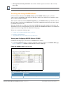
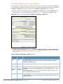
Completing Initial Login
Use your browser to navigate to the static IP address assigned to the internal page of the OV3600. Once your
session launches, the Authentication Dialog Box appears as shown in Figure 7.
Figure 7 Authentication Dialog Box
Perform these steps to complete the initial login.
1. Enter User name: admin
2. Enter Password: admin
3. Click: OK
OV3600 pages are protected via SSL.
NOTE
After successful authentication, your browser launches the OV3600 Home Overview page.
NOTE
Alcatel-Lucent recommends changing the default login and password on the OV3600 Setup > Users page. Refer to
the procedure “Creating OV3600 User Roles” on page 47 for additional information.
OmniVista 3600 Air Manager (OV3600) User Guide | Version 6.3
Installing The OmniVista 3600 Air Manager (OV3600) | 35
36 | Installing The OmniVista 3600 Air Manager (OV3600)
OmniVista 3600 Air Manager (OV3600) User Guide | Version 6.3
Chapter 3
Configuring the OmniVista Air
Manager (OV3600)
Introduction
This chapter provides several tasks for initial configuration of OV3600 on the network after installation is
complete. This chapter describes all pages accessed from the OV3600 Setup tab and describes two pages in
the Device Setup tab—the Communication and Upload Files pages. Once required and optional
configurations in this chapter are complete, continue to later chapters in this document to create and
deploy device groups and device configuration and discovery on the network.
This chapter contains the following procedures to deploy initial OV3600 configuration:
Required or Important Configurations
Defining General OV3600 Server Settings
Defining OV3600 Network Settings
Creating OV3600 Users
Creating OV3600 User Roles
Enabling OV3600 to Manage Your Devices
Additional and Advanced Configurations
NOTE
Configuring TACACS+ and RADIUS Authentication
Configuring Cisco WLSE and WLSE Rogue Scanning
Configuring ACS Servers
Integrating OV3600 with an Existing Network Management Solution (NMS)
Integrating a RADIUS Accounting Server
Auditing PCI Compliance on the Network
Deploying WMS Offload
Overview of WMS Offload in OV3600
General Configuration Tasks Supporting WMS Offload in OV3600
Additional Information Supporting WMS Offload
Additional configurations of multiple types are available after basic configurations in this chapter are complete. This
chapter focuses on required configurations, or optional configurations that often precede other tasks described in
later chapters.
OmniVista 3600 Air Manager (OV3600) User Guide | Version 6.3
Configuring the OmniVista Air Manager (OV3600) | 37
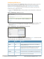
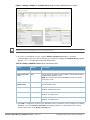
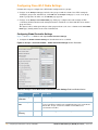
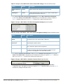
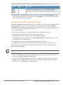
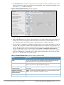
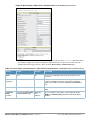
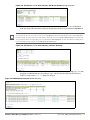
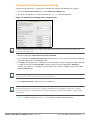
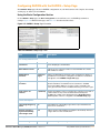
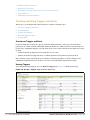
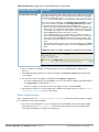
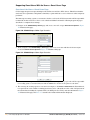
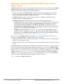
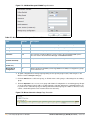
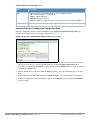
Defining General OV3600 Server Settings
The first step in configuring OV3600 is to specify the general settings for the OV3600 server. Figure 8
illustrates the page in which these settings are defined and changed. This page features the following major
sections:
General
Display Options
Configuration Options
External Syslog
Historical Data Retention
Default Firmware Upgrade Options
Additional OV3600 Services
Performance Tuning
Figure 8 OV3600 Setup > General Page Illustration
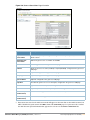
Perform the following steps to configure the general OV3600 server settings.
38 | Configuring the OmniVista Air Manager (OV3600)
OmniVista 3600 Air Manager (OV3600) User Guide | Version 6.3
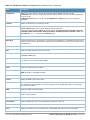
1. Browse to the OV3600 Setup > General page, locate the General area, and enter the information
described in
Table 6:
Table 6 OV3600 Setup > General Page > General Section Fields and Default Values
Setting
Default
Description
System Name
OV3600
Defines your name for the OV3600 server, with a maximum limit of 20
alphanumeric characters.
Automatically
Monitor/Manage New
Devices
No
Launches a drop-down menu that specifies the behavior OV3600 should
follow when it discovers a new device. Devices are placed in the default
group which is defined on the Groups > List page.
Default Group
NA
Sets the device group that this OV3600 server uses as the default for
device-level configuration. Select a device group from the drop-down
menu. A group must first be defined on the Groups > List page to appear
in this drop-down menu. For additional information, refer to Chapter 4,
“Configuring and Using Device Groups in OV3600” on page 75.
Device Configuration
Audit Interval
Daily
If enabled, this setting defines the interval of OV3600 queries, in which
each device compares actual device settings to the Group configuration
policies stored in the OV3600 database. If the settings do not match, the
AP is flagged as mismatched and OV3600 sends an alert via email, log, or
SNMP.
OV3600 recommends enabling this feature with a frequency of Daily or
more frequently to ensure that your AP configurations comply with your
established policies.
Automatically Repair
Misconfigured
Devices
Disabled
If enabled, this setting automatically reconfigures the settings on the
device when OV3600 detects a variance between actual device settings
and the Group configuration policy in the OV3600 database.
Send Debugging
Messages to OV3600
Wireless
Enabled
If enabled, OV3600 automatically emails any system errors to the OV3600
Support Center to assist in debugging.
Nightly Maintenance
Time (00:00 - 23:59)
04:15
Specifies the time of day OV3600 should perform daily maintenance.
During maintenance, OV3600 cleans the database, performs backups, and
completes a few other housekeeping tasks. Such processes should not be
performed during peak hours of bandwidth demand.
OV3600 User
Authorization
Lifetime
(0-240 min)
120
Sets the amount of time, in minutes, that an OV3600 user session lasts
before the user must authenticate when a new browser window is opened.
Setting the lifetime to 0 requires the user to log in every time a new
browser window is opened.
Check Updates from
OV3600 Wireless
Yes
Enables OV3600 to check automatically for multiple update types. Check
daily for OV3600 updates, to include enhancements, device template files,
important security updates, and other important news. This setting
requires a direct internet connection via OV3600.
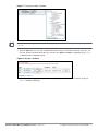
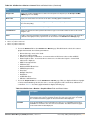
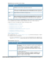
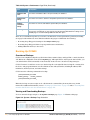
2. On the OV3600 Setup > General page, locate the Display Options section and adjust settings as required.
The Display Options section configures which Group tabs and options appear by default in new device
groups.
Changes to this section apply across all of OV3600. These changes affect all users and all new device groups.
NOTE
Table 7 describes the settings and default values in this section.
OmniVista 3600 Air Manager (OV3600) User Guide | Version 6.3
Configuring the OmniVista Air Manager (OV3600) | 39
Table 7 OV3600 Setup > General > Display Options Section Fields and Default Values
Setting
Default
Description
Use Fully
Qualified
Domain Names
No
Sets OV3600 to use fully qualified domain names for APs instead of the AP
name. For example, "testap.yourdomain.com" would be used instead of
"testap."
This option is supported only for Cisco IOS, Alcatel-Lucent, and Alcatel-Lucent
devices.
Show VendorSpecific Device
Settings For
All Devices
Displays a drop-down menu that determines which Group tabs and options are
viewable by default in new groups, and selects the device types that use fully
qualified domain names. This field has three options, as follows:
All Devices—When selected, OV3600 displays all Group tabs and setting
options.
Only Devices on this OV3600—When selected, OV3600 hides all options
and tabs that do not apply to the APs and devices currently on OV3600.
Selected device types—When selected, this option allows the user to
specify the device types for which OV3600 displays Group settings.
Look Up
Wireless User
Hostnames
Yes
Enables OV3600 to look up automatically the DNS for new user hostnames.
This setting can be turned off to troubleshoot performance issues.
DNS Hostname
Lifetime
24 hours
Defines the length of time, in hours, for which a DNS server hostname remains
valid on OV3600, after which OV3600 refreshes DNS lookup. Select a time
duration from the drop-down menu. Options are as follows:
1 hour
2 hours
4 hours
12 hours
24 hours
3. On the OV3600 Setup > General page, locate the Configuration Options section and adjust settings as
required. The settings in this field configure whether certain changes can be pushed to devices in
monitor-only mode. Table 8 describes the settings and default values of this section.
Table 8 OV3600 Setup > General > Configuration Options Section Fields and Default Values
Setting
Default
Description
Allow Guest User
Configuration in
Monitor-Only Mode
No
When Yes is selected, new Cisco WLC and Alcatel-Lucent guest
access users can be pushed to the controller while the controller is
in monitor-only mode in OV3600. The controller does not reboot as
a result of the push.
Allow WMS Offload
Configuration in
Monitor-Only Mode
(for Alcatel-Lucent
devices only)
No
When Yes is selected, you can enable the Alcatel-Lucent WMS
offload feature on the Groups > Basic page for OmniAccess WLAN
Switches in monitor-only mode. Enabling WMS offload does not
cause a controller to reboot.
Keep Unreferenced
Alcatel-Lucent
Configuration
No
Allows OV3600 to retain unused AOS-W configuration profiles
pertaining to Alcatel-Lucent Configuration. With Alcatel-Lucent
Configuration, you can define profiles on an OmniAccess WLAN
Switch but it is not necessary to reference them from a virtual AP
configuration or other component of Alcatel-Lucent Configuration.
Normally OV3600 deletes unreferenced profiles, but this setting
retains them when enabled with Yes.
4. On the OV3600 Setup > General page, locate the External Syslog section and adjust settings as required.
Table 9 describes these settings and default values.
40 | Configuring the OmniVista Air Manager (OV3600)
OmniVista 3600 Air Manager (OV3600) User Guide | Version 6.3
Table 9 OV3600 Setup > General > External Syslog Section Fields and Default Values
Setting
Default
Description
Include Event Log
Messages
No
Enables the external syslog to include messages from the event log.
Include Audit Log
Messages
No
Enables the external syslog to include messages from the audit log.
5. On the OV3600 Setup > General page, locate the Historical Data Retention section and specify the number
of days you wish to keep client session records and rogue discovery events. Table 10 describes the
settings and default values of this section.
Table 10 OV3600 Setup > General > Historical Data Retention Fields and Default Values
Setting
Default
Description
Inactive User Data
(2-1500 days)
60
Defines the number of days OV3600 stores basic information about inactive
users. OV3600 recommends a shorter setting of 60 days for customers with
high user turnover such as hotels or convention centers. The longer you
store inactive user data, the more hard disk space you require.
User Association
History (2-550 days)
14
Defines the number of days OV3600 stores client session records. The
longer you store client session records, the more hard disk space you
require.
Tag History
(2-550 days)
14
Sets the number of days OV3600 retains location history for Wi-Fi tags.
Rogue AP Discovery
Events (2-550 days)
14
Defines the number of days OV3600 stores Rogue Discovery Events. The
longer you store discovery event records, the more hard disk space you
require.
Reports (2-550 days)
60
Defines the number of days OV3600 stores Reports. Large numbers of
reports, over 1000, can cause the Reports > List page to be slow to
respond.
Automatically
Acknowledged
Alerts (0-550 days)
14
Defines automatically acknowledged alerts as the number of days OV3600
retains alerts that have been automatically acknowledged. Setting this value
to 0 disables this function.
Acknowledged
Alerts (2-550 days)
60
Defines the number of days OV3600 retains information about
acknowledged alerts. Large numbers of Alerts, over 2000, can cause the
System > Alerts page to be slow to respond.
Traps from Managed
Devices (0-550 days)
14
Defines the number of days OV3600 retains information about SNMP traps
from Managed Devices. Setting this value to 0 disables this function.
Archived Device
Configurations
(1-100)
10
Sets the number of archived configurations to retain for each device.
Guest Users
(0-550 days)
30
Sets the number of days that OV3600 is to support any guest user. Setting
this value to 0 disables this function.
Closed Helpdesk
Incidents
30
Sets the number of days that OV3600 is to retain records of closed Helpdesk
incidents once closed. Settings this value to 0 disables this function.
OmniVista 3600 Air Manager (OV3600) User Guide | Version 6.3
Configuring the OmniVista Air Manager (OV3600) | 41
Table 10 OV3600 Setup > General > Historical Data Retention Fields and Default Values (Continued)
Setting
Default
Description
Inactive SSIDs
425
Sets the number of days OV3600 retains historical information after OV3600
last saw a client on a specific SSID. Settings this value to 0 disables this
function.
6. On the OV3600 Setup > General page, locate the Default Firmware Upgrade Options section and adjust
settings as required. This section allows you to configure the default firmware upgrade behavior for
OV3600. Table 11 describes the settings and default values of this section.
Table 11 OV3600 Setup > General > Default Firmware Upgrade Options Fields and Default Values
Setting
Default
Description
Allow Firmware
upgrades in
Monitor-Only mode
No
If yes is selected, OV3600 upgrades the firmware for APs in Monitor-Only
mode. When OV3600 upgrades the firmware in this mode, the desired
configuration are not be pushed to OV3600. Only the firmware is applied. The
firmware upgrade may result in configuration changes. OV3600 does not
correct those changes when the AP is in Monitor-Only mode.
Simultaneous Jobs
(1-20)
20
Defines the number of jobs OV3600 runs at the same time. A job can include
multiple APs.
Simultaneous
Devices per Job
(1-1000)
20
Defines the number of devices that can be in the process of upgrading at the
same time. OV3600 only runs one TFTP transfer at a time. As soon as the
transfer to a device has completed, the next transfer begins, even if the first
device is still in the process of rebooting or verifying configuration.
Failures Before
Stopping (0-20)
1
Sets the default number of upgrade failures before OV3600 pauses the
upgrade process. User intervention is required to resume the upgrade process.
Setting this value to 0 disables this function.
7. On the OV3600 Setup > General page, locate the Additional OV3600 Services section, and adjust settings
as required. Table 12 describes the settings and default values of this section.
Table 12 OV3600 Setup > General > Additional OV3600 Services Fields and Default Values
Setting
Default
Description
Enable FTP
Server
No
Enables or disables the FTP server on OV3600. The FTP server is only used to
manage Cisco Aironet 4800 APs. OV3600 recommends disabling the FTP server if
you do not have any Cisco Aironet 4800 APs in the network.
Enable
RTLS
Collector
No
Enables or disables the RTLS Collector, which is used to allow OmniAccess WLAN
Switches to send RTLS packets to VisualRF. The RTLS server IP address must be
configured on each controller. This function is used for VisualRF to improve location
accuracy and to locate chirping asset tags. This function is supported only for AlcatelLucent and Alcatel-Lucent devices.
Use
Embedded
Mail Server
Yes
Enables or disables the embedded mail server that is included with OV3600.
This field supports a Send Test Email button for testing server functionality. Clicking
this button prompts you with a To and From field in which you must enter valid email
addresses, and a button to send a test email.
8. On the OV3600 Setup > General page, locate the Performance Tuning section. Performance tuning is
unlikely to be necessary for many OV3600 implementations, and likely provides the most improvements
for customers with extremely large Pro or Enterprise installations. Please contact OV3600 support if you
think you might need to change any of these settings. Table 13 describes the settings and default values
of this section.
42 | Configuring the OmniVista Air Manager (OV3600)
OmniVista 3600 Air Manager (OV3600) User Guide | Version 6.3
Table 13 OV3600 Setup > General > Performance Tuning Fields and Default Values
Setting
Default
Description
Monitoring
Processes
Based on the
number of cores for
your server
Optional setting configures the throughput of monitoring data.
Increasing this setting allows OV3600 to process more data per
second, but it can take resources away from other OV3600 processes.
Please contact OV3600 Support if you think you might need to increase
this setting for your network.
Maximum number
of configuration
processes
5
Increases the number of processes that are pushing configurations to
your devices, as an option. The optimal setting for your network
depends on the resources available, especially RAM. Please contact
OV3600 Support if you think you might need to increase this setting for
your network.
Maximum number 3
of audit processes
Increases the number of processes that audit configurations for your
devices, as an option. The optimal setting for your network depends on
the resources available, especially RAM. Contact OV3600 Support if
you are considering increasing this setting for your network.
Verbose Logging
of SNMP
Configuration
No
Enables or disables logging detailed records of SNMP configuration
information.
SNMP Rate
Limiting for
Monitored
Devices
No
Enables or disables a maximum bandwidth consumption threshold for
each port for monitored devices. This setting prevents unnecessary
SNMP traffic from compromising device performance.
9. Click Save when the General Server settings are complete and whenever making subsequent changes.
What Next?
Navigate to additional tabs in the OV3600 Setup section to continue additional setup configurations.
Complete the required configurations in this chapter prior to proceeding to ensuing chapters of this
document. OV3600 Support remains available to you for any phase of OV3600 installation.
Defining OV3600 Network Settings
The next step in configuring OV3600 is to confirm the OV3600 network settings. Define these settings by
navigating to the OV3600 Setup > Network page. Figure 9 illustrates the contents of this page.
Figure 9 OV3600 Setup > Network Page Illustration
Perform the following steps to define the OV3600 network settings:
1. Locate the Primary Network Interface section. The information in this section should match what you
defined during initial network configuration and should not require changes. Table 14 describes the
settings and default values.
OmniVista 3600 Air Manager (OV3600) User Guide | Version 6.3
Configuring the OmniVista Air Manager (OV3600) | 43
Table 14 OV3600 Setup > Network, Primary Network Interface Fields and Default Values
Setting
Default
Description
IP Address
None
Sets the IP address of the OV3600 network interface.
This address must be static IP address.
Hostname
None
Sets the DNS name assigned to the OV3600 server.
Subnet Mask
None
Sets the subnet mask for the OV3600 primary network interface.
Gateway
None
Sets the default gateway for the OV3600 network interface.
Primary DNS IP
None
Sets the primary DNS IP address for the OV3600 network interface.
Secondary DNS IP
None
Sets the secondary DNS IP address for the OV3600 network interface.
2. On the OV3600 Setup > Network page, locate the Network Time Protocol (NTP) section. The Network Time
Protocol is used to synchronize the time between OV3600 and your network reference server.
NOTE
Specifying NTP servers is optional. The servers synchronize the time on the OV3600 server, not on individual
access points.
To disable NTP services, clear both the Primary and Secondary NTP server fields. Any problem related to
communication between OV3600 and the NTP servers creates an entry in the event log.
Table 15 describes the settings and default values in more detail.
Table 15 OV3600 Setup > Network > Secondary Network Fields and Default Values
Setting
Default
Description
Primary
ntp1.yourdomain.com
Sets the IP address or DNS name for the primary Network Time Protocol
server.
Secondary ntp2.yourdomain.com
Sets the IP address or DNS name for the secondary Network Time
Protocol server.
3. On the OV3600 Setup > Network page, locate the External Syslog area. Use this section to configure
OV3600 to send audit and system events to an external syslog server. Table 16 describes these settings
and default values.
Table 16 OV3600 Setup > Network > External Syslog Fields and Default Values
Setting
Default
Description
Include event log
messages
No
Select yes radio button to send event log messages to an external syslog server.
Include audit log
messages
No
Select yes radio button to send audit log messages to an external syslog server.
4. On the OV3600 Setup > Network page, locate the Static Routes area. This section displays network,
subnet mask, and gateway settings that you have defined elsewhere from a command-line interface.
This section does not enable you to configure new routes or remove existing routes.
NOTE
44 | Configuring the OmniVista Air Manager (OV3600)
OmniVista 3600 Air Manager (OV3600) User Guide | Version 6.3
5. Click Save when you have completed all changes on the OV3600 Setup > Network page, or click Revert to
return to the last settings. Clicking Save restarts any affected services and may disrupt temporarily your
network connection.
What Next?
Navigate to additional tabs in the OV3600 Setup section to continue additional setup configurations.
Complete the required configurations in this chapter prior to proceeding to ensuing chapters of this
document. OV3600 Support remains available to you for any phase of OV3600 installation.
Creating OV3600 Users
OV3600 installs with only one OV3600 user—the administrator or admin user. The admin user has these
parameters authorizations within OV3600:
The admin user is able to define additional users with varying levels of privilege, be it manage read/write
or monitoring.
The admin user can limit the viewable devices as well as the type of access a user has to the devices.
For each general user that you add, you define a Username, Password and a Role. You use the username and
password when logging into OV3600. It is helpful to use unique and meaningful user names as they are
recorded in the log files when you or other users make changes in OV3600.
The user role defines the user type, access level, and the top folder for that user. User roles are defined on
the OV3600 Setup > Roles page. Refer to the next procedure in this chapter for additional information,
“Creating OV3600 User Roles” on page 47.
The admin user can provide optional additional information about the user including the user's real name,
email address, phone number, and so forth.
Perform the following steps to display, add, edit, or delete OV3600 users of any privilege level. You must be
an admin user to complete these steps.
1. Navigate to the OV3600 Setup > Users page. This page displays all users currently configured in OV3600.
Figure 10 illustrates the contents and layout of this page.
Figure 10 OV3600 Setup > Users Page Illustration
2. Click Add to create a new user, click the pencil icon to edit an existing user, or select a user and click
Delete to remove that user from OV3600. When you click Add or the edit icon, the Add User page
appears, illustrated in Figure 11.
OmniVista 3600 Air Manager (OV3600) User Guide | Version 6.3
Configuring the OmniVista Air Manager (OV3600) | 45
Figure 11 OV3600 Setup > Users > Add/Edit User Page Illustration
3. Enter or edit the settings on this page. Table 17 describes these settings in additional detail.
Table 17 OV3600 Setup > User > Add/Edit User Fields and Default Values
Setting
Default
Description
Username
None
Sets the username as an alphanumeric string. The Username is used when logging
in to OV3600 and appears in OV3600 log files.
Role
None
Specifies the User Role that defines the Top viewable folder, type and access level
of the user specified in the previous field.
The admin user defines user roles on the OV3600 Setup > Roles page, and each
user in the system is assigned to a role.
Password
None
Sets the password for the user being created or edited. Enter an alphanumeric
string without spaces, and enter the password again in the Confirm Password
field.
Because the default user's password is identical to the name, OV3600 strongly
recommends that your change this password. OV3600 strongly recommends that
you immediately change the default OV3600 "admin" password for admin users.
Name
None
Allows you to define an optional and alphanumeric text field that takes note of the
user's actual name.
E-Mail
Address
None
Allows you to define an optional email address. This email address propagates
throughout many additional pages in OV3600 for that user, to include reports,
triggers, and alerts.
Phone
None
Allows you to enter an optional phone number for the user.
Notes
None
Enables you to cite any additional notes about the user, including the reason they
were granted access, the user's department, or job title.
4. Click Add to create the new user, click Save to retain changes to an existing user, or click Cancel to
cancel out of this screen. The user information you have configured appears on the OV3600 Setup >
Users page and the user propagates to all additional OV3600 pages and functions relevant to that user.
OV3600 enables user roles to be created with access to folders within multiple branches of the overall hierarchy.
This feature assists non-administrator users who support a subset of accounts or sites within a single OV3600
deployment, such as help desk or IT staff.
NOTE
In prior OV3600 versions, user roles could be assigned only to a single top folder, such as "West Coast" or
"European Stores", for example. User roles can now be restricted to multiple folders within the overall hierarchy,
even if they do not share the same top-level folder. Non-administrator users are only able to see data and users for
devices within their assigned subset of folders.
46 | Configuring the OmniVista Air Manager (OV3600)
OmniVista 3600 Air Manager (OV3600) User Guide | Version 6.3
What Next?
Navigate to additional tabs in the OV3600 Setup section to continue additional setup configurations.
Complete the required configurations in this chapter prior to proceeding to ensuing chapters of this
document. OV3600 Support remains available to you for any phase of OV3600 installation.
Creating OV3600 User Roles
The OV3600 Setup > Roles page defines the viewable devices, the operations that can be performed on
devices, and general OV3600 access. VisualRF uses the same user roles as defined for OV3600—users can see
floor plans that contain an AP to which they have access in OV3600, although only visible APs appear on the
floorplan.
Users can also see any building that contains a visible floorplan, and any campus that contains a visible
building. When a new role is added to OV3600, VisualRF must be restarted for the new user to be enabled.
Refer to the VisualRF User Guide for additional information.
User Roles can be created that have access to folders within multiple branches of the overall hierarchy. This
feature assists non-administrative users, such as help desk or IT staff, who support a subset of accounts or
sites within a single OV3600 deployment. In prior OV3600 releases, OV3600 user roles could only be
assigned to a single top folder (such as "West Coast" or "European Stores"). User roles can now be restricted
to multiple folders within the overall hierarchy even if they do not share the same top-level folder. Nonadmin users are only be able to see data and users for devices within their assigned subset of folders.
Perform the following steps to view, add, edit, or delete user Roles:
1. Navigate to the OV3600 Setup > Roles page. This page displays all roles currently configured in OV3600.
Figure 10 illustrates the contents and layout of this page.
Figure 12 OV3600 Setup > Roles Page Illustration
2. Click Add to create a new role, click the pencil icon to edit an existing role, or select a role and click
Delete to remove that role from OV3600. When you click Add or the edit icon, the Add Role page appears,
illustrated in Figure 13.
OmniVista 3600 Air Manager (OV3600) User Guide | Version 6.3
Configuring the OmniVista Air Manager (OV3600) | 47
Figure 13 OV3600 Setup > Roles > Add/Edit Role Page Illustration
3. Enter or edit the settings on this page. Table 17 describes these settings in additional detail.
As explained earlier in this section, Roles define the type of user-level access, the user-level privileges,
and the user viewability for device groups and devices in OV3600. Table 18 describes the settings and
default values of this section.
Table 18 OV3600 Setup > Roles > Roles Fields and Default Values
Setting
Default
Description
Name
None
Sets the administrator-definable string that names the role. OV3600
recommends that the role name give an indication of the devices and groups
that are viewable, as well as the privileges granted to that role.
Enabled
Yes
Disables or enables the role. Disabling a role prevents all users of that role from
logging in to OV3600.
Type
AP/Device
Manager
AP/Device Access
Level
None
48 | Configuring the OmniVista Air Manager (OV3600)
Defines the type of role. OV3600 supports the following types of roles:
OV3600 Administrator—The OV3600 Administrator has full access to
OV3600 and all of the devices. The administrator can view and edit all
settings and all APs in OV3600. Only the OV3600 Administrator can create
new Users or access the OV3600 Setup page.
AP/Device Manager—AP/Device Managers have access to a limited
number of devices and groups based on the Top folder and varying levels
of control based on the Access Level.
OV3600 Management Client—Defines the OV3600 user. The user
information defined in AMC must match the user with the OV3600
Management Client type.
Guest Access Sponsor—Limited-functionality role to allow helpdesk or
reception desk staff to grant wireless access to temporary personnel. This
role only has access to the defined top folder of APs.
Defines the privileges the role has over the viewable APs. OV3600 supports
three privilege levels, as follows:
Manage (Read/Write)—Manage users have read/write access to the
viewable devices and Groups. They can change all OV3600 settings for the
devices and Groups they can view.
Audit (Read Only)—Audit users have read only access to the viewable
devices and Groups. Audit users have access to the APs/Devices > Audit
page, which may contain sensitive information including AP passwords.
Monitor (Read Only)—Monitor users have read only access to the devices
and Groups. Monitor users can not view the APs/Devices > Audit page
which may contain sensitive information, including AP passwords.
OmniVista 3600 Air Manager (OV3600) User Guide | Version 6.3
Table 18 OV3600 Setup > Roles > Roles Fields and Default Values (Continued)
Setting
Default
Description
Top Folder
None
Defines the Top viewable folder for the role. The role is able to view all devices
and groups contained by the Top folder. The top folder and its subfolders must
contain all of the devices in any of the groups it can view.
NOTE: OV3600 Version 6.3 enhances folder viewability as defined by roles.
Version 6.3 enables user roles to be created with access to folders within
multiple branches of the overall hierarchy. This feature assists nonadministrator users who support a subset of accounts or sites within a single
OV3600 deployment, such as help desk or IT staff.
Prior to Version 6.3, OV3600 user roles could be assigned only to a single top
folder, such as "West Coast" or "European Stores", for example. User roles can
now be restricted to multiple folders within the overall hierarchy, even if they do
not share the same top-level folder. Non-administrator users are only able to
see data and users for devices within their assigned subset of folders.
RAPIDS
None
Sets the RAPIDS privileges, which are set separately from the APs/Devices.
This field specifies the RAPIDS privileges for the role, and options are as
follows:
None—Cannot view the RAPIDS tab or any Rogue APs.
Read Only—The user can view the RAPIDS pages but cannot make any
changes to rogue APs or perform OS scans.
Read/Write—The user may ignore, delete, override scores and perform OS
scans.
Helpdesk
No
Sets the role to support helpdesk users, with parameters that are specific to
the needs of helpdesk personnel supporting users on a wireless network.
Enable Adobe
Flash
Yes
Enables the Adobe Flash application for all users who are assigned this role.
Adobe Flash supports dynamic graphics on the Home > Overview page,
VisualRF, Quickview functions, and additional OV3600 pages.
What Next?
Navigate to additional tabs in the OV3600 Setup section to continue additional setup configurations.
Complete the required configurations in this chapter prior to proceeding to ensuing chapters of this
document. OV3600 Support remains available to you for any phase of OV3600 installation.
Enabling OV3600 to Manage Your Devices
Once OV3600 is installed and active on the network, the next task is to define the basic settings that allow
OV3600 to communicate with and manage your devices. Device-specific firmware files are often required or
are highly desirable. Furthermore, the use of Web Auth bundles is advantageous for deployment of Cisco
Airespace/WLC wireless LAN controllers when they are present on the network.
This section contains the following procedures:
Configuring Communication Settings for Discovered Devices
Loading Device Firmware onto OV3600
Overview of the Device Setup > Upload Files Page
Loading Firmware Files to OV3600 6.3
Overview
Loading
Using
of the Device Setup > Upload Files Page
Firmware Files to OV3600 6.3
Web Auth Bundles in OV3600
OmniVista 3600 Air Manager (OV3600) User Guide | Version 6.3
Configuring the OmniVista Air Manager (OV3600) | 49
Configuring Communication Settings for Discovered Devices
To configure OV3600 to communicate with your devices and to define the default shared secrets and SNMP
polling information, navigate to the Device Setup > Communication page, illustrated in Figure 14.
Figure 14 Device Setup > Communication Page Illustration
50 | Configuring the OmniVista Air Manager (OV3600)
OmniVista 3600 Air Manager (OV3600) User Guide | Version 6.3
Perform the following steps to define the default credentials and SNMP settings for the wireless network.
1. On the Device Setup > Communication page, locate the Default Credentials area. Enter the credentials for
each device model on your network. The default credentials are assigned to all newly discovered APs.
To change the credentials of APs already managed and monitored by OV3600, use the Edit button for the
device.
NOTE
Community strings and shared secrets must have read-write access for OV3600 to configure the devices. Without
read-write access, OV3600 may be able to monitor the devices but cannot apply any configuration changes.
2. Browse to the Device Setup > Communication page, locate the SNMP Settings area, and enter or revise
the following information. Table 19 lists the settings and default values.
Table 19 Device Setup > Communication > SNMP Settings Fields and Default Values
Setting
Default
Description
SNMP
Timeout
3
Sets the time, in seconds, that OV3600 waits for a response from a device
after sending an SNMP request.
SNMP Retries
3
Sets the number of times OV3600 tries to poll a device when it does not
receive a response within the SNMP Timeout period. If OV3600 does not
receive an SNMP response from the device after the specified number of
retries, OV3600 classifies that device as Down.
3. On the Device Setup > Communication page, locate the Telnet/SSH Settings section, and complete or
adjust the default value for the field in this section. Table 20 lists the setting and default value.
Table 20 Device Setup > Communication > Telnet/SSH Settings Fields and Default Values
Setting
Default
Description
Telnet/SSH
Timeout
(3-120 sec)
10
Sets the timeout period in seconds used when performing Telnet and SSH
commands.
4. On the Device Setup > Communication page, locate the HTTP Discovery Settings section. Complete or
revise the default values for the settings in this section. Table 21 lists these settings and default values.
Table 21 Device Setup > Communication > HTTP Discovery Settings Fields and Default Values
Setting
Default
Description
HTTP Timeout
(3-120 sec)
5
Sets the timeout period in seconds used when running an HTTP discovery scan.
5. On the Device Setup > Communication page, locate the ICMP Settings section. Complete the settings or
revise the default values as required. Table 22 itemizes the setting and default value of this section.
Table 22 Device Setup > Communication > ICMP Settings Fields and Default Values
Setting
Default
Description
Attempt to
ping down
devices
Yes
Enables a function that applies when an AP is unreachable over SNMP.
When Yes is selected, this option has OV3600 attempt to ping the AP device.
Select No if performance is affected in negative fashion by this function. If a large
number of APs are unreachable by ICMP, likely to occur where there is in excess of
100 APs, the timeouts start to impede network performance.
NOTE: If ICMP is disabled on the network, select No to avoid the performance penalty
caused by numerous ping requests.
OmniVista 3600 Air Manager (OV3600) User Guide | Version 6.3
Configuring the OmniVista Air Manager (OV3600) | 51
6. On the Device Setup > Communication page, locate the Colubris Administration Options section You only
need to provide this information if you use Colubris APs on your network. Select one of the three
options listed. Table 23 itemizes these settings and default values.
Table 23 Device Setup > Communication > Colubris Administration Options Fields and Default
Values
Setting
Default
Description
Do Not Modify
Security/HTTPS
Settings
N/A
Enables OV3600 to use only an existing user account on the AP. This user account
must have all permissions set. The user accounts are defined in the Colubris
Username/Password section in the Default Secrets area.
Create and use a
specified user
N/A
Enables OV3600 to replace the existing user with a new user account (specified
below) on each AP, with all permissions enabled.
New Colubris
Username and
Password
N/A
Specifies the username and password to be used only if the option Replace
existing user with specified user is selected.
7. On the Device Setup > Communication page, locate the Cisco Aironet VxWorks User Creation Options
section. You only need to provide this information if you use VxWorks-based Cisco APs on your
network, as follows:
Aironet 340
Aironet 350
Aironet 1200
Select one of the three options listed. Table 24 describes the settings and default values of this section.
Table 24 Device Setup > Communication > Cisco Aironet VxWorks User Creation Options Fields
and Default Values
Setting
Default
Description
Do Not Modify N/A
Security/SNMP
Settings
Enables OV3600 using only an existing user account on the AP, as defined in the
Cisco VxWorks Username/Password section in the Default Secrets area. This
user account must have all permissions set.
N/A
Enables OV3600 to create a new user account, specified below, on each AP, with
all permissions enabled.
Create and
Use Specified
User
8. On the Device Setup > Communication page, locate the Symbol 4131/Intel 2011b and Cisco Aironet IOS
SNMP Initialization area. You only need to provide this information if you use Symbol 4131, Intel 2011b,
or Cisco Aironet IOS access points. Select one of the options listed. Table 25 describes the settings and
default values.
Table 25 Device Setup > Communications Fields and Default Values
Setting
Default
Description
Do Not Modify SNMP
Settings
Yes
When selected, specifies that OV3600 not modify any SNMP
settings. If SNMP is not already initialized on the Symbol, Intel, and
Cisco IOS APs, OV3600 is not able to manage them.
Enable Read-Write SNMP
No
When selected, and when on networks where the Symbol, Intel, and
Cisco IOS APs do not have SNMP initialized, this setting enables
SNMP so the devices can be managed by OV3600.
52 | Configuring the OmniVista Air Manager (OV3600)
OmniVista 3600 Air Manager (OV3600) User Guide | Version 6.3
9. On the Device Setup > Communication page, locate the Symbol 4131/Intel 2011b and Cisco Aironet IOS
SNMP Initialization area. You only need to provide this information if you use Symbol 4131, Intel 2011b,
or Cisco Aironet IOS access points. Select one of the options listed. Table 25 describes the settings and
default values.
Table 26 Device Setup > Communications Fields and Default Values
Setting
Default
Description
Do Not Modify SNMP
Settings
Yes
When selected, specifies that OV3600 not modify any SNMP
settings. If SNMP is not already initialized on the Symbol, Intel, and
Cisco IOS APs, OV3600 is not able to manage them.
Enable Read-Write SNMP
No
When selected, and when on networks where the Symbol, Intel, and
Cisco IOS APs do not have SNMP initialized, this setting enables
SNMP so the devices can be managed by OV3600.
Loading Device Firmware onto OV3600
Overview of the Device Setup > Upload Files Page
OV3600 enables automated firmware distribution to the devices on your network. Once you have
downloaded the firmware files from the manufacturer, you can upload this firmware to OV3600 for
distribution to devices via the Device Setup > Upload Files page. This is optional.
Figure 15 illustrates the Upload Files page, which lists all firmware files on OV3600 with file information.
This page also enables you to add new firmware files, to delete firmware files, and to add New Web Auth
Bundle files.
The following additional pages in OV3600 6.3 support firmware file information:
Firmware files uploaded to OV3600 on this Upload File page appear as options in the drop-down menus
on the Group > Firmware page and on individual AP/Device > Manage pages. These firmware files can be
applied automatically to devices through OV3600.
Use the OV3600 Setup page to configure OV3600-wide default firmware options.
Figure 15 Device Setup > Upload Files Page Illustration
Table 27 below itemizes the contents, settings, and default values for the Upload Files page.
OmniVista 3600 Air Manager (OV3600) User Guide | Version 6.3
Configuring the OmniVista Air Manager (OV3600) | 53
Table 27 Device Setup > Upload Files Fields and Default Values
Setting
Default
Description
Type
None
Displays a drop-down list of the primary AP makes and models that OV3600
supports with automated firmware distribution.
Owner Role
None
Displays the user role that uploaded the firmware file. This is the role that has
access to the file when an upgrade is attempted.
Description
None
Displays a user-configurable text description of the firmware file.
Server Protocol
None
Displays the file transfer protocol by which the firmware file was obtained from
the server.
Use Group File
Server
None
Displays the name of the file server supporting the group.
Firmware
Filename
None
Displays the name of the file that was uploaded to OV3600 and to be transferred
to an AP when the file is used in an upgrade.
Firmware
Version
None
Displays the firmware version number. This is a user-configurable field.
Firmware MD5
Checksum
None
Displays the MD5 checksum of the file after it was uploaded to OV3600. The MD5
checksum is used to verify that the file was uploaded to OV3600 without issue.
The checksum should match the checksum of the file before it was uploaded.
Firmware File
Size
None
Displays the size of the firmware file in bytes.
HTML Filename
None
Supporting HTML, displays the name of the file that was uploaded to OV3600
and to be transferred to an AP when the file is used in an upgrade.
HTML Version
None
Supporting HTML, displays the version of HTML used for file transfer.
HTML MD5
Checksum
None
Supporting HTML, displays the MD5 checksum of the file after it was uploaded to
OV3600. The MD5 checksum is used to verify that the file was uploaded to
OV3600 without issue. The checksum should match the checksum of the file
before it was uploaded.
HTML File Size
None
Supporting HTML, displays the size of the file in bytes.
Desired
Firmware File for
Specified
Groups
None
The firmware file is set as the desired firmware version on the Groups >
Firmware Files page of the specified groups. You cannot delete a firmware file
that is set as the desired firmware version for a group.
Loading Firmware Files to OV3600 6.3
Perform the following steps to load a device firmware file onto OV3600.
1. Browse to the Device Setup > Upload Files page.
2. From the Upload Files page, click the Add button. The Add Firmware File dialog box appears. Figure 16
illustrates this page.
54 | Configuring the OmniVista Air Manager (OV3600)
OmniVista 3600 Air Manager (OV3600) User Guide | Version 6.3
Figure 16 Device Setup > Upload Files > Add Firmware Page Illustration
3. Click the Supported Firmware Versions and Features link to view a list of supported firmware versions.
NOTE
Unsupported and untested firmware may cause device mismatches and other problems. Please contact OV3600
Support before installing non-certified firmware.
4. Enter the appropriate information and click the Add button. The file uploads to OV3600 and once
complete, this file appears on the Device Setup > Upload Files page. This file also appears on additional
pages that display firmware files (such as the Group > Firmware page and on individual AP/Device >
Manage pages).
5. You can also import a CSV list of groups and their external TFTP firmware servers.
Table 28 itemizes the settings of this page.
Table 28 Supported Firmware Versions and Features Fields and Default Values
Setting
Default
Description
Type
None
Indicates the firmware file is used with the specified type. If you select an IOS
device from the Type drop-down menu, you have the option of choosing a
server protocol of TFTP or FTP. If you choose FTP you may notice that the
firmware files are pushed to the device more quickly.
Firmware Version
None
Provides a user-configurable field to specify the firmware version number.
Description
None
Provides a user-configurable text description of the firmware file.
Upload firmware
Built-in
files (and use builtin firmware file
server)
Selects the TFTP server that access points use to download their firmware. The
built-in TFTP server is recommended.
If you choose to use an external TFTP server, enter the File Server IP address
and the Filename.
Use an external
firmware file server
You can also choose to assign the external TFTP server on a per-group basis. If
you check that box, you must enter the IP address on the Groups > Firmware
page.
TFTP Server IP
None
Firmware Filename None
Provides the IP address of the External TFTP Server (like SolarWinds) that is
used for the firmware upgrade. This option displays when the user selects Use
a Different TFTP server option.
Enter the filename of the firmware file that needs to be uploaded. Ensure that
the firmware file is in the TFTP root directory.
Click the Browse button to locate the appropriate Intel or Symbol HTML
firmware file on your network.
OmniVista 3600 Air Manager (OV3600) User Guide | Version 6.3
Configuring the OmniVista Air Manager (OV3600) | 55
NOTE
Fields only appear for Intel and Symbol APs. Intel and Symbol distribute their firmware in two separate files: an
image file and an HTML file. Both files must be uploaded to OV3600 for the firmware to be distributed successfully
via OV3600.
6. Click Add to import the firmware file.
7. To delete a firmware file that has already been uploaded to OV3600, return to the File Upload page, select
the checkbox for the firmware file and click Delete.
NOTE
A firmware file may not be deleted if it is the desired version for a group. Use the Group > Firmware page to
investigate this potential setting and status.
Using Web Auth Bundles in OV3600
Web authentication bundles are configuration files that support Cisco Airespace/WLC wireless LAN
controllers. OV3600 6.1 and later OV3600 versions support Web Auth bundles.
This procedure requires that you have local or network access to a Web Auth configuration file for Cisco
Airespace/WLC devices.
Perform these steps to add or edit Web Auth bundles in OV3600.
1. Navigate to the Device Setup > Upload Files page. This page displays any existing Web Auth bundles that
are currently configured in OV3600, and allows you to add or delete Web Auth bundles.
2. Scroll to the bottom of the page. Click Add New Web Auth Bundle to create a new Web Auth bundle, or
click the pencil icon next to an existing bundle to edit. You may also delete Web Auth bundles by
selecting that bundle with the checkbox, and clicking Delete.
When you add or edit a Web Auth bundle, the Web Auth Bundle page appears, as illustrated in Figure 17.
Figure 17 Add Web Auth Bundle Page Illustration
3. Enter a descriptive label in the description field. This is the label by which you identify and track Web
Auth bundles on the Device Setup > Upload Files page once they are present in OV3600.
4. Enter the path and filename of the Web Auth configuration file in the Web Auth Bundle field. Click
Browse to locate the file with the browsing method, as required.
5. Click Add to complete the Web Auth bundle creation, click Save if replacing a previous Web Auth
configuration file, or click Cancel to abort the Web Auth integration.
6. The Device Setup > Upload files page displays your changes.
For additional information and a case study that illustrates the use of Web Auth bundles with Cisco
Airespace/WLC controllers, refer to the following document on Cisco.com:
Wireless LAN Controller Web Authentication Configuration Example, Document ID: 69340
http://www.cisco.com/en/US/tech/tk722/tk809/
technologies_configuration_example09186a008067489f.shtml
56 | Configuring the OmniVista Air Manager (OV3600)
OmniVista 3600 Air Manager (OV3600) User Guide | Version 6.3
Configuring TACACS+ and RADIUS Authentication
You can configure OV3600 to use an external user database to simplify password management for OV3600
administrators and users. These configurations are optional. This section contains the following
procedures:
Configuring TACACS+ Authentication
Configuring RADIUS Authentication and Authorization
Integrating a RADIUS Accounting Server
Configuring TACACS+ Authentication
For TACACS+ capability, you must configure the IP/Hostname of the TACACS+ server, the TCP port, and
the server shared secret. Perform these steps to configuration TACACS+ authentication:
1. Navigate to the OV3600 Setup > Authentication page. This page displays current status of TACACS+.
Figure 18 illustrates this page when neither TACACS+ nor RADIUS authentication is enabled in OV3600.
Figure 18 OV3600 Setup > Authentication Page Illustration When Authentication is Disabled
2. Click No to disable or Yes to enable TACACS+ authentication. If you click Yes, several new fields appear.
Complete the fields described in Table 29.
Table 29 OV3600 Setup > Authentication Fields and Default Values
Field
Default
Description
Primary Server
Hostname/IP
Address
N/A
Enter the IP address or the hostname of the primary TACACS+ server.
Primary Server Port
49
Enter the TCP port for the primary TACACS+ server.
Primary Server
Secret
N/A
Specify the primary shared secret for the primary TACACS+ server, and
confirm in the Confirm field.
Secondary Server
Hostname/IP
Address
N/A
Enter the IP address or the hostname of the secondary TACACS+ server.
Secondary Server
Port
49
Enter the TCP port for the secondary TACACS+ server.
Secondary Server
Secret
N/A
Enter the shared secret for the secondary TACACS+ server.
3. Click Save to retain these configurations, and continue with additional steps.
4. To configure Cisco ACS to work with OV3600, you must define a new service named OV3600 that uses
https on the ACS server.
The OV3600 https service is added to the TACACS+ (Cisco) interface under the Interface
Configuration tab.
OmniVista 3600 Air Manager (OV3600) User Guide | Version 6.3
Configuring the OmniVista Air Manager (OV3600) | 57
Select a checkbox for a new service.
Enter OV3600 in the service column and https in the protocol column.
Click Save.
5. Edit the existing groups or users in TACACS to use the "OV3600 service" and define a role for the group
or user.
The role defined on the Group Setup page in ACS must match the exact name of the role defined on
the OV3600 Setup > Roles page.
The defined role should use the following format: role=<name_of_OV3600_role>. One example is
as follows:
role=DormMonitoring
As with routers and switches, OV3600 does not need to know usernames.
6. OV3600 also needs to be configured as an AAA client.
On the Network Configuration page, click Add Entry to add an AAA client.
Enter the IP address of OV3600 as the AAA Client IP Address.
The secret should be the same value that was entered on the OV3600 Setup > TACACS+ page.
7. Select TACACS+ (Cisco IOS) in the Authenticate Using drop down menu and click submit + restart.
NOTE
OV3600 checks the local username and password store before checking with the TACACS+ server. If the user is
found locally, the local password and local role apply.
What Next?
Navigate to additional tabs in the OV3600 Setup section to continue additional setup configurations.
Complete the required configurations in this chapter prior to proceeding to ensuing chapters of this
document. OV3600 Support remains available to you for any phase of OV3600 installation.
58 | Configuring the OmniVista Air Manager (OV3600)
OmniVista 3600 Air Manager (OV3600) User Guide | Version 6.3
Configuring RADIUS Authentication and Authorization
For RADIUS capability, you must configure the IP/Hostname of the RADIUS server, the TCP port, and the
server shared secret. Perform these steps to configuration RADIUS authentication:
1. Navigate to the OV3600 Setup > Authentication page. This page displays current status of RADIUS. Figure
18 illustrates this page when neither TACACS+ nor RADIUS authentication is enabled in OV3600.
Figure 19 OV3600 Setup > Authentication Page Illustration When Authentication is Disabled
2. Click No to disable or Yes to enable TACACS+ nor RADIUS authentication. If you click Yes, several new
fields appear. Complete the fields described in Table 29.
Table 30 OV3600 Setup > Authentication Fields and Default Values
Field
Default
Description
Primary Server
Hostname/IP
Address
N/A
Enter the IP address or the hostname of the primary RADIUS server.
Primary Server Port
49
Enter the TCP port for the primary RADIUS server.
Primary Server
Secret
N/A
Specify the primary shared secret for the primary RADIUS server, and
confirm in the Confirm field.
Secondary Server
Hostname/IP
Address
N/A
Enter the IP address or the hostname of the secondary RADIUS server.
Secondary Server
Port
49
Enter the TCP port for the secondary RADIUS server.
Secondary Server
Secret
N/A
Enter the shared secret for the secondary RADIUS server.
3. Click Save to retain these configurations, and continue with additional steps in the next procedure.
Integrating a RADIUS Accounting Server
OV3600 first checks its own database prior to checking the RADIUS server database.
NOTE
As an optional configuration, OV3600 supports RADIUS server accounting. The OV3600 Setup > Radius
Accounting page enables this configuration, allowing OV3600 to receive RADIUS accounting records from a
wide variety of RADIUS-based authentication servers and APs. OV3600 uses these records to correlate each
user’s MAC address to an AP with a user name from the authentication server. This capability allows
OV3600 to monitor and track each user by name rather than by MAC address.
OmniVista 3600 Air Manager (OV3600) User Guide | Version 6.3
Configuring the OmniVista Air Manager (OV3600) | 59
This is an optional configuration, enabling the advanced functionality just described. This capability is not
required for basic OV3600 operation, but can increase the user-friendliness of OV3600 administration in
large networks. Figure 20 illustrates the settings of this optional configuration interface.
Perform the following steps and configurations to enable OV3600 to receive accounting records from a
separate RADIUS server. Figure 20 illustrates the display of RADIUS accounting clients already configured,
and Figure 21 illustrates the Add RADIUS Accounting Client page.
Figure 20 OV3600 Setup > Radius Accounting Page Illustration
Figure 21 OV3600 Setup > RADIUS > Add RADIUS Accounting Client Page Illustration
1. To specify the RADIUS authentication server or network, browse to the OV3600 Setup > RADIUS
Accounting page and click Add, illustrated in Figure 21, and provide the information described in Table 31.
Table 31 OV3600 Setup > Radius Accounting Fields and Default Values
Setting
Default
Description
Nickname
None
Sets a user-defined name for the authentication server.
IP/Network
None
Cites the IP address or DNS Hostname for the authentication server if you only want
to accept packets from one device. To accept packets from an entire network enter
the IP/Netmask of the network (for example, 10.51.0.0/24).
(Confirm)
Shared Secret
None
Sets the Shared Secret that is used to establish communication between OV3600
and the RADIUS authentication server.
2. Click Add.
What Next?
For additional information about configuring WLAN Gateways or WLAN Controllers such as
BlueSocket, ReefEdge, or ProCurve wireless gateways, refer to “Third-Party Security Integration for
OV3600” on page 303.
Navigate to additional tabs in the OV3600 Setup section to continue additional setup configurations.
Complete the required configurations in this chapter prior to proceeding to ensuing chapters of this
document. OV3600 Support remains available to you for any phase of OV3600 installation.
60 | Configuring the OmniVista Air Manager (OV3600)
OmniVista 3600 Air Manager (OV3600) User Guide | Version 6.3
Configuring Cisco WLSE and WLSE Rogue Scanning
These are optional configurations that support Cisco WLSE and WLSE-based rogue scanning in OV3600.
This section contains the following topics and procedures, and several of these sections have additional
sub-procedures:
Introduction to Cisco WLSE
Configuring WLSE Initially in OV3600
Configuring IOS APs for WDS Participation
Configuring ACS for WDS Authentication
Configuring Cisco WLSE Rogue Scanning
You must enter one or more CiscoWorks Wireless LAN Solution Engine hosts to be polled for discovery of
Cisco devices and for rogue AP information
Introduction to Cisco WLSE
Cisco WLSE functions as an integral part of the Cisco SWAN architecture, which includes IOS Access
Points, a Wireless Domain Service, an Access Control Server, and a WLSE. In order for OV3600 to obtain
Rogue AP information from the WLSE, all SWAN components must be properly configured. Table 32
describes these components.
Table 32 Cisco SWAN Architecture Components
SWAN Component
Requirements
WDS
WDS Name
Primary and backup IP address for WDS devices (IOS AP or WLSM)
WDS Credentials APs within WDS Group
NOTE: WDS can be either a WLSM or an IOS AP. WLSM (WDS) can control up to 250
access points. AP (WDS) can control up to 30 access points.
WLSE
ACS
APs
IP Address
Login
IP Address
Login
APs within WDS Group
Configuring WLSE Initially in OV3600
Use the following general procedures to configure and deploy a WLSE device in OV3600:
Adding an ACS Server for WLSE
Enabling Rogue Alerts for Cisco WLSE
Configuring WLSE to Communicate with APs
Discovering Devices
Managing Devices
Inventory Reporting
Defining Access
Grouping
WDS Participation
Primary or Secondary WDS
OmniVista 3600 Air Manager (OV3600) User Guide | Version 6.3
Configuring the OmniVista Air Manager (OV3600) | 61
Adding an ACS Server for WLSE
1. Navigate to the Devices > Discover > AAA Server page.
2. Select New from the drop-down list.
3. Enter the Server Name, Server Port (default 2002), Username, Password, and Secret.
4. Click Save.
Enabling Rogue Alerts for Cisco WLSE
1. Navigate to the Faults > Network Wide Settings > Rogue AP Detection page.
2. Select the Enable toggle.
3. Click Apply.
Additional information about rogue device detection is available in “Configuring Cisco WLSE Rogue
Scanning” on page 64.
Configuring WLSE to Communicate with APs
1. Navigate to the Device Setup > Discover page.
2. Configure SNMP Information (click for additional information).
3. Configure HTTP Information (click for additional information).
4. Configure Telnet/SSH Credentials (click for additional information).
5. Configure HTTP ports for IOS access points (click for additional information).
6. Configure WLCCP credentials (click for additional information).
7. Configure AAA information (click for additional information).
Discovering Devices
There are three methods to discover access points within WLSE, as follows:
CDP
Import from a file.
Import from CiscoWorks.
Perform these steps to discover access points.
1. Navigate to the Device > Managed Devices > Discovery Wizard page.
2. Import devices from a file (click for additional information).
3. Import devices from Cisco Works (click for additional information).
4. Import using CDP (click for additional information).
Managing Devices
Prior to enabling radio resource management on IOS access points, the access points must be under WLSE
management.
NOTE
OV3600 becomes the primary management/monitoring vehicle for IOS access points, but for OV3600 to gather
Rogue information, the WLSE must be an NMS manager to the APs.
Use these pages to make such configurations:
1. Navigate to Device > Discover > Advanced Options.
2. Select the method to bring APs into management Auto, or specify via filter (click for additional
information).
62 | Configuring the OmniVista Air Manager (OV3600)
OmniVista 3600 Air Manager (OV3600) User Guide | Version 6.3
Inventory Reporting
When new devices are managed, the WLSE generates an inventory report detailing the new APs. OV3600
accesses the inventory report via the SOAP API to auto-discover access points. This is an optional step to
enable another form of AP discovery in addition to OV3600' CDP, SNMP scanning, and HTTP scanning
discovery for Cisco IOS access points. Perform these steps for inventory reporting.
1. Navigate to Devices > Inventory > Run Inventory.
2. Run Inventory executes immediately between WLSE polling cycles (click for additional information).
Defining Access
OV3600 requires System Admin access to WLSE. Use these pages to make these configurations.
1. Navigate to Administration > User Admin.
2. Configure Role and User.
Grouping
It is much easier to generate reports or faults if APs are grouped in WLSE. Use these pages to make such
configurations.
1. Navigate to Devices > Group Management.
2. Configure Role and User.
Configuring IOS APs for WDS Participation
IOS APs (1100, 1200) can function in three roles within SWAN:
Primary WDS
Backup WDS
WDS Member
WDS Participation
Perform these steps to configure WDS participation.
1. Log in to the AP.
2. Navigate to the Wireless Services > AP page.
3. Click Enable participation in SWAN Infrastructure.
4. Click Specified Discovery and enter the IP address of the Primary WDS device (AP or WLSM).
5. Enter the Username and Password for the WLSE server.
Primary or Secondary WDS
Perform these steps to configure primary or secondary functions for WDS.
1. Navigate to the Wireless Services > WDS > General Setup page.
2. If the AP is the Primary or Backup WDS, select Use the AP as Wireless Domain Services.
Select Priority (set 200 for Primary, 100 for Secondary).
Configure the Wireless Network Manager (configure the IP address of WLSE).
3. If the AP is Member Only, leave all options unchecked.
4. Navigate to the Security > Server Manager page.
5. Enter the IP address and Shared Secret for the ACS server.
6. Click the Apply button.
7. Navigate to the Wireless Services > WDS > Server Group page.
OmniVista 3600 Air Manager (OV3600) User Guide | Version 6.3
Configuring the OmniVista Air Manager (OV3600) | 63
8. Enter the WDS Group of AP.
9. Select the ACS server in the Priority 1 drop- down menu.
10. Click the Apply button.
Configuring ACS for WDS Authentication
ACS authenticates all components of the WDS and must be configured first. Perform these steps to make
this configuration.
1. Login to the ACS.
2. Navigate to the System Configuration > ACS Certificate Setup page.
3. Install a New Certificate by clicking the Install New Certificate button, or skip to the next step if the
certificate was previously installed.
4. Click the User Setup button in the left frame.
5. Enter the Username that will be used to authenticate into the WDS and click Add/Edit button.
6. Enter the Password that will be used to authenticate into the WDS and click the Submit button.
7. Navigate to the Network Configuration > Add AAA Client page.
8. Add AP Hostname, AP IP Address, and Community String (for the key).
9. Enter the Password that will be used to authenticate into the WDS and click the Submit button.
For additional and more general information about ACS, refer to “Configuring ACS Servers” on page 66.
Configuring Cisco WLSE Rogue Scanning
The OV3600 Setup > WLSE page allows OV3600 to integrate with the Cisco Wireless LAN Solution Engine
(WLSE). OV3600 can discover APs and gather rogue scanning data from the Cisco WLSE.
Figure 22 illustrates and itemizes the OV3600 settings for communication that is enabled between OV3600
and WLSE.
Figure 22 OV3600 Setup > WLSE Page Illustration
Perform the following steps for optional configuration of OV3600 for support of Cisco WLSE rogue
scanning.
1. To add a Cisco WLSE server to OV3600, navigate to the OV3600 Setup > WLSE page and click Add.
Complete the fields in this page. Table 33 describes the settings and default values.
64 | Configuring the OmniVista Air Manager (OV3600)
OmniVista 3600 Air Manager (OV3600) User Guide | Version 6.3
Table 33 OV3600 Setup > WLSE Fields and Default Values
Setting
Default
Description
IP Address/ Hostname
None
This field designates the IP address or DNS Hostname for the
WLSE server, which must already be configured on the Cisco WLSE
server.
Protocol
HTTP
This drop-down menu specifies the protocol to be used when
polling the WLSE.
Port
1741
This field defines the port OV3600 uses to communicate with the
WLSE server.
Username
None
This field defines the username OV3600 uses to communicate with
the WLSE server. The username and password must be configured
the same way on the WLSE server and on OV3600.
The user needs permission to display faults to discover rogues and
inventory API (XML API) to discover manageable APs. As derived
from a Cisco limitation, only credentials with alphanumeric
characters (that have only letters and numbers, not other symbols)
allow OV3600 to pull the necessary XML APIs.
Password
None
This field defines the password OV3600 uses to communicate with
the WLSE server. The username and password must be configured
the same way on the WLSE server and on OV3600.
As derived from a Cisco limitation, only credentials with
alphanumeric characters (that have only letters and numbers, not
other symbols) allow OV3600 to pull the necessary XML APIs.
Poll for AP Discovery;
Poll for Rogue Discovery
Yes
This option sets the method by which OV3600 uses WLSE to poll
for discovery of new APs and/or new rogue devices on the network.
Last Contacted
None
This field displays the last time OV3600 was able to contact the
WLSE server.
Polling Period
10 minutes
This setting determines how frequently OV3600 polls WLSE to
gather rogue scanning data.
Error
None
To aid in debugging, this field displays helpful error messages if
errors occur.
2. After you have completed all fields, click the Save button. OV3600 is now configured to gather rogue
information from WLSE rogue scans. As a result of this configuration, any rogues found by WLSE appear
on the RAPIDS > Rogue page.
What Next?
Navigate to additional tabs in the OV3600 Setup section to continue additional setup configurations.
Complete the required configurations in this chapter prior to proceeding to ensuing chapters of this
document. OV3600 Support remains available to you for any phase of OV3600 installation.
OmniVista 3600 Air Manager (OV3600) User Guide | Version 6.3
Configuring the OmniVista Air Manager (OV3600) | 65
Configuring ACS Servers
This is an optional configuration. The OV3600 Setup > ACS page allows OV3600 to poll one or more Cisco
ACS servers for wireless username information. When you specify an ACS server, OV3600 gathers
information about your networks wireless users. Refer to the “Configuring TACACS+ and RADIUS
Authentication” on page 57 section if you want to use your ACS server to manage your OV3600 users.
Perform these steps to configure ACS servers:
1. Navigate to the OV3600 Setup > ACS page. This page displays current ACS information, as illustrated in
Figure 23.
Figure 23 OV3600 Setup > ACS Page Illustration
2. Click Add to create a new ACS server, or click a pencil icon to edit an existing server. To delete an ACS
server, select that server and click Delete. When clicking Add or edit, the Details page appears, as
illustrated in Figure 24.
Figure 24 OV3600 Setup > ACS > Add/Edit Details Page Illustration
3. Complete the settings on the OV3600 Setup > ACS > Add/Edit Details page. Table 34describes these fields:
Table 34 OV3600 Setup > ACS > Add/Edit Details Fields and Default Values
Field
Default
Description
IP/Hostname
None
Sets the DNS name or the IP address of the ACS Server.
Protocol
HTTP
Launches a drop-down menu specifying the protocol OV3600 uses
when it polls the ACS server.
Port
2002
Sets the port through which OV3600 communicates with the ACS.
OV3600 generally communicates via SNMP traps on port 162.
Username
None
Sets the Username of the account OV3600 uses to poll the ACS server.
Password
None
Sets the password of the account OV3600 uses to poll the ACS server.
Polling Period
10 min
Launches a drop-down menu that specifies how frequently OV3600
polls the ACS server for username information.
66 | Configuring the OmniVista Air Manager (OV3600)
OmniVista 3600 Air Manager (OV3600) User Guide | Version 6.3
4. Click Add to finish creating the new ACS server, or click Save to finish editing an existing ACS server.
5. The ACS server must have logging enabled for passed authentications. To configure your ACS server to
log the required information, you must enable the Log to CSV Passed Authentications report option, as
follows:
Log in to the ACS server, select System Configuration, then in the Select frame, click the Logging link.
Under Enable Logging, click the CSV Passed Authentications link. The default logging options function
and support OV3600. These include the two columns OV3600 requires: User-Name and Caller-ID.
What Next?
Navigate to additional tabs in the OV3600 Setup section to continue additional setup configurations.
Complete the required configurations in this chapter prior to proceeding to ensuing chapters of this
document. OV3600 Support remains available to you for any phase of OV3600 installation.
Integrating OV3600 with an Existing Network Management
Solution (NMS)
This is an optional configuration. The OV3600 Setup > NMS configuration page allows OV3600 to integrate
with other Network Management Solution (NMS) consoles. This configuration enables advanced and
interoperable functionality as follows:
OV3600 can forward WLAN-related SNMP traps to the NMS, or OV3600 can send SNMPv1 or SNMPv2
traps to the NMS.
OV3600 can be used in conjunction with Hewlett-Packard’s ProCurve Manager.
The necessary files for either type of NMS interoperability are downloaded from the OV3600 Setup >
NMS page as follows. For additional information, contact OV3600 Support.
Perform these steps to configure NMS support in OV3600:
1. Navigate to the OV3600 Setup > NMS page, illustrated in Figure 25.
2. illustrates the contents of this optional NMS configuration.
Figure 25 OV3600 Setup > NMS Integration Page Illustration
3. Click Add to integrate a new NMS server, or click the pencil icon to edit an existing NMS server. Provide
the information described in Table 35:
OmniVista 3600 Air Manager (OV3600) User Guide | Version 6.3
Configuring the OmniVista Air Manager (OV3600) | 67
Figure 26 OV3600 Setup > NMS Integration Add/Edit Page Illustration
Table 35 OV3600 Setup > NMS Integration Add/Edit Fields and Default Values
Setting
Default
Description
Hostname
None
Cites the DNS name or the IP address of the NMS.
Port
162
Sets the port OV3600 uses to communicate with the NMS.
NOTE: OV3600 generally communicates via SNMP traps on port 162.
Community String
None
Sets the community string used to communicate with the NMS.
SNMP Version
v2C
Sets the SNMP version of the traps sent to the Host.
Enabled
Yes
Enables or disables trap logging to the specified NMS.
Send
Configuration
Traps
Yes
Enables NMS servers to transmit SNMP configuration traps.
4. The OV3600 Setup > NMS Integration Add/Edit page features the Netcool/OMNIbus Integration link. IBM
Tivoli Netcool/OMNIbus is operations management software that enables automated event correlation
and additional features resulting in optimized network uptime. Click this link for additional information,
specifications, and brief instructions for installation with OV3600. Figure 27 illustrates this page.
5. The OV3600 Setup > NMS Integration Add/Edit page features the HP ProCurve Manager Integration link.
Click this link for additional information, zip file download, and brief instructions for installation with
OV3600. Figure 27 illustrates this page.
68 | Configuring the OmniVista Air Manager (OV3600)
OmniVista 3600 Air Manager (OV3600) User Guide | Version 6.3
Figure 27 Netcool/OMNIbus Integration and HP ProCurve Manager Integration Information
6. Click Add on the OV3600 Setup > NMS Integration Add/Edit page to finish creating the NMS server, or
click Save to complete configuration of an existing NMS server.
What Next?
Navigate to additional tabs in the OV3600 Setup section to continue additional setup configurations.
Complete the required configurations in this chapter prior to proceeding to ensuing chapters of this
document. OV3600 Support remains available to you for any phase of OV3600 installation.
Auditing PCI Compliance on the Network
This section describes PCI requirements and auditing functions in OV3600, with the following topics:
Introduction to PCI Requirements
Overview of PCI Auditing in OV3600 6.3
Enabling or Disabling PCI Auditing
Overview of WMS Offload in OV3600
Introduction to PCI Requirements
OV3600 supports wide security standards and functions in the wireless network. One core component of
network security is the optional deployment of Payment Card Industry (PCI) Auditing. This chapter describes
PCI requirements, and auditing of PCI compliance on the network using OV3600. Additional and separate
chapters in this guide describe additional security tools, listed at the bottom of this page.
Auditing PCI Compliance
This chapter contains the following section that describes PCI auditing in OV3600:
Overview of PCI Auditing in OV3600 6.3
Enabling or Disabling PCI Auditing
OmniVista 3600 Air Manager (OV3600) User Guide | Version 6.3
Configuring the OmniVista Air Manager (OV3600) | 69
Overview of PCI Auditing in OV3600 6.3
PCI Auditing in the OV3600 Interface
PCI Auditing in OV3600 allows you to monitor, audit, and demonstrate PCI compliance on the network.
There are five primary pages in which you establish, monitor, and access PCI auditing, as follows:
The OV3600 Setup > PCI Compliance page enables or disables PCI Compliance monitoring on the
network, and displays the current compliance status on the network. See “Enabling or Disabling PCI
Auditing” on page 72.
The Reports > Definitions page allows you to create custom-configured and custom-scheduled PCI
Compliance reports. See “Reports > Definitions Page Overview” on page 265.
The Reports > Generated page lists PCI Compliance reports currently available, and allows you to
generate the latest daily version of the PCI Compliance Report with a single click. Refer to “Reports >
Generated Page Overview” on page 266.
The APs/Devices > PCI Compliance page enables you to analyze PCI Compliance for any specific device
on the network. This page is accessible when you select a specific device from the APs/Devices >
Monitor page. First, you must enable this function through OV3600 Setup.See “Enabling or Disabling PCI
Auditing” on page 72.
The PCI Compliance Report offers additional information. Refer to “Using the PCI Compliance Report”
on page 282. Commencing with OV3600 Version 6.3, this report not only contains Pass or Fail status for
each PCI requirement, but cites the action required to resolve a Fail status when sufficient information is
available.
The Payment Card Industry (PCI) Data Security Standard (DSS) establishes multiple levels in which
payment cardholder data is protected in a wireless network. OV3600 supports PCI requirements according
to the standards and specifications set forth by the following authority:
Payment Card Industry (PCI) Data Security Standard (DSS)
PCI Security Standards Council Website
https://www.pcisecuritystandards.org
PCI Quick Reference Guide, Version 1.2 (October 2008)
https://www.pcisecuritystandards.org/pdfs/pci_ssc_quick_guide.pdf
OV3600 6.3 supports auditing network compliance with the following PCI requirements, enabling you to
display real-time PCI compliance data by several criteria. OV3600 grades the network as pass or fail for each
requirement that is enabled.
NOTE
When any PCI requirement is enabled on OV3600 6.3, then OV3600 grades the network as pass or fail for the
respective PCI requirement. Whenever a PCI requirement is not enabled in OV3600 6.3, then OV3600 6.3 does not
monitor the network’s status in relation to that requirement, and cannot designate Pass or Fail network status.
70 | Configuring the OmniVista Air Manager (OV3600)
OmniVista 3600 Air Manager (OV3600) User Guide | Version 6.3
Table 36 PCI Requirements and Support in OV3600 6.3
PCI Requirement Description
1.1
Monitoring configuration standards for network firewall devices
When Enabled: PCI Requirement 1.1 establishes firewall and router configuration standards.
A device fails Requirement 1.1 if it is in read-write management mode and there are
mismatches between the desired configuration and the configuration on the device, for
example.
When Disabled: When this PCI requirement is disabled in OV3600 6.3, firewall router and
device configurations are not checked for PCI compliance in firewall configuration, and Pass
or Fail status is not reported nor monitored.
1.2.3
Monitoring firewall installation between any wireless networks and the cardholder data
environment
When Enabled: A device passes requirement 1.2.3 if it can function as a stateful firewall.
When Disabled: When this PCI requirement is disabled in OV3600 6.3, firewall router and
device installation are not checked for PCI compliance.
2.1
Monitoring the presence of vendor-supplied default security settings
When Enabled: PCI Requirement 2 establishes the standard in which all vendor-supplied
default passwords are changed prior to a device’s presence and operation in the network.
A device fails requirement 2.1 if the username, passwords or SNMP credentials being used
by OV3600 to communicate with the device are on a list of forbidden default credentials. The
list includes common manufacturer default passwords, for example.
When Disabled: When this PCI requirement is disabled in OV3600 6.3, device passwords
and other manufacturer default settings are not checked for PCI compliance.
2.1.1
Changing vendor-supplied defaults for wireless environments
When Enabled: A device fails requirement 2.1.1 if the passphrases, SSIDs, or other securityrelated settings are on a list of forbidden values that OV3600 6.3 establishes and tracks.
The list includes common manufacturer default passwords. The user can input new values to
achieve compliance.
When Disabled: When this PCI requirement is disabled in OV3600 6.3, then network devices
are not checked for forbidden information and PCI Compliance is not established.
4.1.1
Using strong encryption in wireless networks
When Enabled: PCI Requirement 4 establishes the standard by which payment cardholder
data is encrypted prior to transmission across open public networks. PCI disallows WEP
encryption as an approved encryption method after June 20, 2010. A device fails
requirement 4.1.1 if the desired or actual configuration reflect that WEP is enabled on the
network, or if associated users can connect with WEP.
When Disabled: When this PCI monitoring function is disabled in OV3600 6.3, then OV3600
6.3 cannot establish a pass or fail status with regard to PCI encryption requirements on the
network.
11.4
Using intrusion-detection or intrusion-prevention systems to monitor all traffic
When Enabled: OV3600 reports pass or fail status when monitoring devices capable of
reporting IDS events. Recent IDS events are be summarized in the PCI Compliance report or
the IDS Report.
When Disabled: When this function is disabled in OV3600 6.3, then OV3600 does not
monitor the presence of PCI-compliant intrusion detection or prevention systems, nor can it
report Pass or Fail status with regard to IDS events.
OmniVista 3600 Air Manager (OV3600) User Guide | Version 6.3
Configuring the OmniVista Air Manager (OV3600) | 71
Enabling or Disabling PCI Auditing
Perform these steps to verify status and to enable or disable OV3600 6.3 support for PCI 1.2 requirements.
enabling one or all PCI standards on OV3600 6.3 enables real-time information and generated reports that
advise on Pass or Fail status. The PCI auditing supported in OV3600 6.3 is reported in Table 36.
1. To determine what PCI Compliance standards are enabled or disabled on OV3600 6.3, navigate to the
OV3600 Setup > PCI Compliance page, illustrated in Figure 28.
Figure 28 OV3600 Setup > PCI Compliance Page Illustration
2. To enable, disable, or edit any category of PCI Compliance monitoring in OV3600 6.3, click the pencil
icon next to the compliance category you wish to change. The Default Credential Compliance page
displays for the respective PCI standard.
3. Create changes as required. Specific credentials can be cited in the Forbidden Credentials section of any
Edit page to enforce PCI requirements in OV3600 6.3. Figure 29 illustrates one example.
Figure 29 Default Credential Compliance for PCI Requirements
4. Click Save to retain the settings. The PCI Compliance page should reflect changes on the next viewing.
5. To view and monitor PCI auditing on the network, use generated or daily reports. See Chapter 9,
“Creating, Running, and Emailing Reports” . In addition, you can view the real-time PCI auditing of any
given device online. Perform these steps:
a. Navigate to the APs/Devices > List page, click a specific device, and the Monitor page for that device
displays. The Monitor page displays a Compliance page in the menu bar.
b. Click the Compliance page to view complete PCI compliance auditing for that specific device.
72 | Configuring the OmniVista Air Manager (OV3600)
OmniVista 3600 Air Manager (OV3600) User Guide | Version 6.3
What Next?
For additional information about configuring WLAN Gateways or WLAN Controllers such as
BlueSocket, ReefEdge, or ProCurve wireless gateways, refer to “Third-Party Security Integration for
OV3600” on page 303.
Navigate to additional tabs in the OV3600 Setup section to continue additional setup configurations.
Complete the required configurations in this chapter prior to proceeding to ensuing chapters of this
document. OV3600 Support remains available to you for any phase of OV3600 installation.
Deploying WMS Offload
Overview of WMS Offload in OV3600
This section describes the Alcatel-Lucent Wireless LAN Management Server (WMS) offload infrastructure.
WMS Offload is supported with the following two requirements:
AOS-W Version 2.5.4 or later
OV3600 Version 6.0 or later
The Alcatel-Lucent WMS feature is an enterprise-level hardware device and server architecture with
managing software for security and network policy. There are three primary components of the WMS
deployment:
Air Monitor AP devices establish and monitor RF activity on the network.
The WMS server manages devices and network activity, to include rogue AP detection and enforcement
of network policy.
The OV3600 graphical user interface (GUI) allows users to access and use the Alcatel-Lucent WMS
functionality.
In OV3600 Version 6.1 and Version 6.2, WMS Offload is the ability to offload the WMS server data and GUI
functions into OV3600. WMS master controllers provide this data so that OV3600 can support rigorous
network monitoring capabilities. Additional support for WMS Offload continues with upcoming versions of
OV3600.
General Configuration Tasks Supporting WMS Offload in OV3600
WMS Offload must be enabled with a six-fold process and related configuration tasks, as follows:
1. Configure OmniAccess WLAN Switches for optimal OV3600 monitoring.
Disable debugging.
Ensure OV3600 server is a trap receiver host.
Ensure proper traps are enabled.
2. Configure OV3600 to optimally monitor the Alcatel-Lucent infrastructure.
Enable WMS offload.
Configure SNMP communication.
Create a proper policy for monitoring Alcatel-Lucent infrastructure.
Discover the infrastructure.
3. Configure device classification.
Set up rogue classification.
Set up rogue classification override.
Establish user classification override devices.
4. Deploy Alcatel-Lucent-specific monitoring features.
Enable remote AP and wired network monitoring.
View controller license information.
OmniVista 3600 Air Manager (OV3600) User Guide | Version 6.3
Configuring the OmniVista Air Manager (OV3600) | 73
5. Convert existing floor plans to VisualRF, to include the following elements:
MMS
AOS-W
RF Plan
6. Utilize RTLS for increasing location accuracy (optional).
Enable RTLS service on the OV3600 server.
Enable RTLS on Alcatel-Lucent Infrastructure.
Additional Information Supporting WMS Offload
For additional information, to include detailed concepts, configuration procedures, restrictions, AlcatelLucent infrastructure, and OV3600 version differences in support of WMS Offload, refer to the following
resources:
Alcatel-Lucent Best Practices Guide—primary WMS Offload support information
74 | Configuring the OmniVista Air Manager (OV3600)
OmniVista 3600 Air Manager (OV3600) User Guide | Version 6.3
Chapter 4
Configuring and Using Device
Groups in OV3600
Introduction
This chapter describes the deployment of device groups within the Alcatel-Lucent OmniVista 3600 Air
Manager (OV3600). This chapter describes the Groups > List page and several additional focused sub-menus
and pages. Focused sub-menus can vary significantly from one device group to another—not all sub-menus
may be supported for all groups, and this is defined when you create or edit any device group. The Groups
tab can have the following focused sub-menus:
List—This page is the default page in the Groups section of OV3600. This page lists all groups currently
configured in OV3600 and provides the foundation for all group-level configuration, with the exception
of Alcatel-Lucent AP Groups. In this latter case, refer to the Alcatel-Lucent Configuration Guide.
Monitor—This page displays user and bandwidth information, lists devices in a given group, provides an
Alert Summary table for monitoring alerts for the group, and provides a detailed Audit Log for device-
level activity in a given group.
NOTE
The Incidents portion of this Alert Summary table only increments the counter for incidents that are open and
associated to an AP. This is also the case if you click Incidents and view incident details. That is, this field displays
incidents based on folder, which is the Top folder on this page and on the Home > Overview page. Incidents that
are not related to devices in that folder are not counted in this Alert Summary. To view all incidents, including those
not associated to an AP, navigate to the Helpdesk > Incidents page.
Basic—This is the first focused-submenu page to appear when you create a new group with the Add
button on the Groups > List page. Once you define a group name, OV3600 displays the Basic page from
which you configure many group-level settings.
Templates—This page manages templates for any device group. Templates allow you to manage the
configuration of 3Com, Alcatel-Lucent, Aruba, Cisco Aironet IOS, Enterasys, HP, Hirschmann, LANCOM,
Nomadix, Nortel, Symbol and Trapeze devices in a given group using a configuration file. Variables in
such templates configure device-specific properties, such as name, IP address and channel. Variables
also define group-level properties. For additional information about using the Templates page, refer to
“Creating and Using Templates” on page 181.
Security—This page defines general security settings for device groups, to include TACACS+, RADIUS,
and additional security settings on devices.
SSIDs—This page sets SSIDs and related parameters in device groups.
AAA Servers—This page configures authentication, authorization, and accounting settings in support of
TACACS+ and RADIUS servers for device groups.
Radio—This page defines radio settings for device groups.
Cisco WLC Radio—This page defines radio settings specific to Cisco WLC devices in device groups,
when present. In earlier versions of OV3600, this was the Airespace page.
LWAPP APs—This page defines settings specific to AP devices that use the Lightweight Access Point
Protocol (LWAPP).
PTMP/WiMAX—This page defines settings specific to Proxim MP devices when present.
Proxim Mesh—This page defines mesh AP settings specific to Proxim devices when present.
Colubris—This page defines AP settings specific to Colubris devices when present.
OmniVista 3600 Air Manager (OV3600) User Guide | Version 6.3
Configuring and Using Device Groups in OV3600 | 75
MAC ACL—This page defines MAC-specific settings that apply to Proxim, Cisco Vxworks, Symbol, Intel
and Procurve520 devices when present.
Firmware—This page manages firmware files for many devices.
Alcatel-Lucent Config—This page manages Alcatel-Lucent AP Groups, AP Overrides, and other profiles
specific to Alcatel-Lucent devices on the network. Use this page in combination with the Device Setup >
Alcatel-Lucent Configuration page. For additional information, refer to the Alcatel-Lucent Configuration
Guide.
This chapter provides the following procedures for configuring group-level device configurations. These
tasks govern devices on your wireless network.
OV3600 Group Overview
Important Group Concepts
Viewing All Defined Device Groups
Searching in Groups
Configuring Basic Group Settings for the Access Points Group
Configuring Group Security Settings
Configuring Group SSIDs and VLANs
Adding and Configuring Group AAA Servers
Configuring Group Radio Settings
Configuring Cisco WLC Radio Settings
Configuring LWAPP AP Settings
Configuring Group PTMP/WiMAX Settings
Configuring Proxim Mesh Radio Settings
Configuring Colubris Advanced Settings
Configuring Group MAC Access Control Lists
Specifying Minimum Firmware Versions for APs in a Group
Creating New Groups
Deleting a Group
Changing Multiple Group Configurations
Modifying Multiple Devices
Using Global Groups for Group Configuration
OV3600 Group Overview
Important Group Concepts
Enterprise-class APs and controllers are complex devices with hundreds of variable settings that must be
configured precisely to achieve optimal performance and network security. Configuring all settings on each
device individually is time-consuming and prone to human error. OV3600 addresses this challenge by
automating the processes of device configuration and compliance auditing. At the core of this approach is
the concept of groups, with the following functions and benefits:
OV3600 allows certain settings to be managed efficiently at a "Group level" while others are managed at
an "individual device level."
76 | Configuring and Using Device Groups in OV3600
OmniVista 3600 Air Manager (OV3600) User Guide | Version 6.3
OV3600 defines a group as a subset of the devices on the wireless LAN, ranging in size from one device
to hundreds of devices that share certain common configuration settings.
Groups may be defined based on geography (such as “5th Floor APs"), usage or security policies (such
as "Guest Access APs"), function (such as "Manufacturing APs"), or any other variable appropriate for
your business needs.
Devices within a group may be from different manufacturers or hardware models—the core requirement
and benefit of this approach is that all devices within a group share certain basic configuration settings.
Typical group configuration variables include basic settings (SSID, SNMP polling interval, and so forth),
security settings (VLANs, WEP, 802.1x, ACLs, and so forth), and some radio settings (data rates,
fragmentation threshold, RTS threshold, DTIM, preamble, and so forth). When configuration changes are
applied at a group level, they are assigned automatically to every device within that group and applied to
every device in Managed mode.
Individual device settings—such as device name, RF channel selection, RF transmission power, antenna
settings, and so forth—typically cannot and should not be managed at a group level and must be configured
individually to achieve optimal performance. Individual AP settings are configured on the APs/Devices >
Manage configuration page.
With OV3600, you can create as many different groups as required. OV3600 users usually establish groups
that range in size from five to 100 wireless devices.
Group configuration can be enhanced with the OV3600 Global Groups feature; this feature allows you to
create global groups with master configurations that are pushed to individual subscriber groups. More
information is available in “Using Global Groups for Group Configuration” on page 139 as well as the
section on the “Monitoring and Supporting Multiple OV3600 Stations with the Master Console” on page 248.
Viewing All Defined Device Groups
To see a list of all groups that have been defined within OV3600, browse to the Groups > List configuration
page, illustrated in Figure 30. Table 37 describes the contents and functions of this page.
Figure 30 Groups > List Page Illustration
Table 37 Groups > List Page Fields and Default Values
Column
Description
Add New Group
Launches a page that enables you to add a new group by name and to define group
parameters for devices in that group.
OmniVista 3600 Air Manager (OV3600) User Guide | Version 6.3
Configuring and Using Device Groups in OV3600 | 77
Table 37 Groups > List Page Fields and Default Values (Continued)
NOTE
Column
Description
Manage
(pencil icon)
The pencil icon for any existing group provides a hyperlink to the Groups > Basic
configuration page to begin editing Group configuration settings for that group.
Name
Displays a user-defined name that uniquely identifies the group by location, manufacturer,
department or any other identifier (such as "Accounting APs," "Floor 1 APs," "Cisco APs,"
"802.1x APs," and so forth).
Is Global Group
Identifies whether or not the group has been identified as a global group that can be used to
configure subscriber groups. Global groups cannot contain APs and are visible by users of
any role.
Global Group
Displays the global group to which the group is subscribed, if any.
SSID
Column represents the Service Set Identifier (SSID) assigned to all devices within the group.
Total Devices
Column represents the total number of access points contained in the group.
Down
Column represents the number of access points within the group, which are not reachable
via SNMP.
Mismatched
Column represents the number of access points within the group that are in a mismatched
state.
Ignored
Column displays the number of ignored devices in that group.
Users
Column represents the number of mobile users associated with all access points within the
group.
BW (kbps)
Column represents a running average of the sum of bytes in and bytes out for the managed
radio page.
Up/Down Status
Polling Period
Column represents the time between Up/Down SNMP polling periods for each device in the
group. By default, all SNMP polling periods match the Up/Down period. Detailed SNMP
polling period information is available on the Groups > Basic configuration page.
Duplicate
Column represents a hyperlink, and the link creates a new group with the name Copy of
<Group Name> with the same group configuration.
When you first configure OV3600, there is only one pre-defined default group labeled Access Points. If you have no
other groups configured, refer to “Configuring Basic Group Settings for the Access Points Group” on page 79.
Searching in Groups
OV3600 Version 6.3 introduces the ability to search within groups and folders, in addition to support for
search functions in prior OV3600 versions. From the Search field at the top right of any page, or from the
Home > Search page, enter a keyword or text string for which to search. Any match in the following
categories will display as search results:
APs/Devices
Rogues
Tags
Users
Groups
Folders
78 | Configuring and Using Device Groups in OV3600
OmniVista 3600 Air Manager (OV3600) User Guide | Version 6.3
Configuring Basic Group Settings for the Access Points Group
The Groups > Basic configuration page allows you to define basic information for the first OV3600 device
group—the Access Points group. Perform these steps to configure basic group settings for the Access
Points group. You can add or edit additional device groups in OV3600 at any time. For additional
information, refer to “Creating New Groups” on page 136 and many additional procedures in this chapter.
1. Navigate to the Groups > List page, and click the name of the Access Points group. This displays the
Groups > Monitor page; several additional focused sub-menus appear in the OV3600 navigation pane.
2. Click the Basic link in the navigation pane and the Basic configuration page appears for the Access
Points group. Figure 31 illustrates the Basic page.
Figure 31 Groups > Basic Page Illustration for the Initial Access Points Group
OmniVista 3600 Air Manager (OV3600) User Guide | Version 6.3
Configuring and Using Device Groups in OV3600 | 79
3. Define the settings in the Basic section for the Access Points group. Table 38 describes the settings and
default values of this Basic section.
Table 38 Groups > Basic Page, Basic Section Fields and Default Values
Setting
Default
Description
Name
Access Points
Sets a user-definable name that uniquely identifies the group by location,
manufacturer, department or any other identifier (such as “Accounting APs,”
“Floor 1 APs,” “Cisco APs,” “802.1x APs,” and so forth).
Missed SNMP
Poll Threshold
1
Sets the number of Up/Down SNMP polls that must be missed before OV3600
considers an AP to be down. The number of SNMP retries and the SNMP
timeout of a poll can be set on the Device Setup > Communication page.
Regulatory
Domain
United States
Sets the regulatory domain in OV3600, limiting the selectable channels for APs
in the group.
Timezone
OV3600
System Time
Allows group configuration changes to be scheduled relative to the time zone
in which the access points are located. This setting is used for scheduling
group-level configuration changes.
Allow One-toOne NAT for
Groups
No
Allows OV3600 to talk to the devices on a different IP address than the one
configured on the device.
NOTE: If enabled, the LAN IP Address listed on the AP/Devices > Manage
configuration page under the Settings area is different than the IP Address
under the Device Communication area.
4. Complete the SNMP Polling Periods section. The information in this section overrides default settings.
Table 39 describes the SNMP polling settings.
Table 39 Groups Basic Page, SNMP Polling Period Section Fields and Default Values
Setting
Default
Description
Up/Down Status Polling
Period
5 minutes
Sets time between Up/Down SNMP polling for each device in the
group.
The Group SNMP Polling Interval overrides the global parameter
configured on the Device Setup > Communication configuration
page. Alcatel-Lucent recommends an initial polling interval of 5
minutes for most networks.
Override Polling Period for
Other Services
No
Radio button enables or disables overriding the base SNMP Polling
Period. If you select Yes for this field, then the other settings in the
SNMP Polling Periods section are activated, and you can override
default values.
User Data Polling Period
5 minutes
Sets time between SNMP polls for User Data for devices in the
group.
Thin AP Discovery Polling
Period
5 minutes
Sets time between SNMP polls for Thin AP Device Discovery.
Controllers are the only devices affected by this polling interval.
Device-to-Device link
Polling Period
5 minutes
Sets time between SNMP polls for Device-to-Device link polling.
Mesh APs are the only devices affected by this polling interval
Device Bandwidth Polling
Period
5 minutes
Sets the interval at which OV3600 polls for the bandwidth being
used by a device.
802.11 Counters Polling
Period
5 minutes
Sets time between SNMP polls for 802.11 Counter information.
80 | Configuring and Using Device Groups in OV3600
OmniVista 3600 Air Manager (OV3600) User Guide | Version 6.3
Table 39 Groups Basic Page, SNMP Polling Period Section Fields and Default Values (Continued)
Setting
Default
Description
Rogue AP and Device
Location Data Polling
Period
5 minutes
Sets time between SNMP polls for Rogue AP and Device Location
Data polling.
CDP Neighbor Data Polling
Period
30 minutes
Sets the frequency in which this group polls the network for Cisco
Discovery Protocol (CDP) neighbors.
5. To record additional information and comments about the group, enter text information in the Notes
section.
6. To configure which options and tabs are visible for the group, complete the settings in the Group Display
Options section. Table 40 describes the settings and default values.
Table 40 Groups > Basic Page, Group Display Options Section Fields and Default Values
Setting
Default
Description
Show device
settings for:
Only Devices
on this OV3600
Drop-down menu determines which Group tabs and options are to be viewable
by default in new groups. Settings include the following:
All Devices—OV3600 displays all Group tabs and setting options.
Only Devices in this group—OV3600 hides all options and tabs that do
not apply to the APs and devices currently in the group.
Only Devices on this OV3600—OV3600 hides all options and tabs that do
not apply to the APs and devices currently on OV3600.
Use system defaults—Use the default settings defined on the OV3600
configuration page
Selected device types—Allows the user to specify the device types for
which OV3600 displays Group settings.
7. To assign dynamically a range of static IP addresses to new devices as they are added into the group,
locate the Automatic Static IP Assignment section on the Groups > Basic configuration page. If you select
Yes in this section, additional fields appear. Complete these fields as required. Table 41 describes the
settings and default values.
Table 41 Groups > Basic Page, Automatic Static IP Assignment Section Field and Default Values
Setting
Default
Description
Assign Static
IP Addresses
to Devices
No
Enables OV3600 to statically assign IP addresses from a specified range to all
devices in the Group.
Start IP
Address
Blank
Sets the first address OV3600 assigns to the devices in the Group.
Number of
Addresses
Blank
Sets the number of addresses in the pool from which OV3600 can assign IP
addresses.
Subnet Mask
Blank
Sets the subnet mask to be assigned to the devices in the Group.
Subnet
Gateway
Blank
Sets the gateway to be assigned to the devices in the Group.
Next IP
Address
Blank
Defines the next IP address queued for assignment. This field is disabled for
the initial Access Points group.
OmniVista 3600 Air Manager (OV3600) User Guide | Version 6.3
Configuring and Using Device Groups in OV3600 | 81
8. To configure Spanning Tree Protocol on WLSE devices and Proxim APs, locate the Spanning Tree
Protocol section on the Groups > Basic configuration page. Adjust these settings as required. Table 42
describes the settings and default values.
Table 42 Groups > Basic Page, Spanning Tree Protocol Section Fields and Default Values
Setting
Default
Description
Spanning Tree
Protocol
Yes
Enables or disables Spanning Tree Protocol on WLSE devices and Proxim APs.
Bridge Priority
32768
Sets the priority for the AP. Values range from 0 to 65535. Lower values have higher
priority. The lowest value is the root of the spanning tree. If all devices are at default
the device with the lowest MAC address will become the root.
Bridge
Maximum Age
20
Sets the maximum time, in seconds, that the device stores protocol information.
The supported range is from 6 to 40.
Bridge Hello
Time
2
Sets the time, in seconds, between Hello message broadcasts.
Bridge
Forward Delay
15
Sets the time, in seconds, that the port spends in listening and learning mode if the
spanning tree has changed.
9. To configure NTP settings locate the NTP section and adjust these settings as required. Table 43
describes the settings and default values.
Table 43 Groups > Basic Page, NTP Section Fields and Default Values
Setting
Default
Description
NTP Server
#1,2,3
None
Sets the IP address of the NTP server that is to be configured on the AP.
UTC Time
zone
0
Sets the hour offset from UTC time to local time for the AP. Times displayed in
OV3600 graphs and logs use the time set on the OV3600 server.
Daylight
Saving Time
Disabled
Enables or disables the advanced daylight saving time settings in the Proxim and
HP ProCurve 420 sections of the Groups > Basic configuration page.
10. To configure Cisco IOS/VxWorks specific settings locate the Cisco IOS/VxWorks section and adjust these
settings as required. Table 44 describes the settings and default values.
Table 44 Groups > Basic Page, Cisco IOS/VxWorks Section Fields and Default Values
Setting
Default
Description
Cisco IOS SNMP
Version
2c
Drop-down menu specifies the version of SNMP used by OV3600 to
communicate to the AP.
Cisco IOS CLI
Communication
Telnet
Sets the protocol OV3600 uses to communicate with Cisco IOS devices.
Selecting SSH uses the secure shell for command line page (CLI)
communication. Selecting Telnet sends the data in clear text via Telnet.
Cisco IOS Config
File
Communication
TFTP
Sets the protocol OV3600 uses to communicate with Cisco IOS devices.
Selecting SCP uses the secure copy protocol for file transfers. Selecting
TFTP will use the insecure trivial file transfer protocol. The SCP login and
password should be entered in the Telnet username and password fields.
Track Usernames
on Cisco Aironet
VxWorks APs
No
Configures VxWorks APs to send SNMP packets to OV3600.
82 | Configuring and Using Device Groups in OV3600
OmniVista 3600 Air Manager (OV3600) User Guide | Version 6.3
11. To configure settings specific to Cisco WLC, locate the Cisco WLC section and adjust these settings as
required. Table 45 describes the settings and default values.
Table 45 Group > Basic Page, Cisco WLC Section Fields and Default Values
Setting
Default
Description
Cisco WLC SNMP Version
2c
Drop-down menu specifies the version of SNMP used by
OV3600 to communicate to WLC controllers.
SNMP Trap Receiver 1,2,3
None
Specifies the IP addresses of the SNMP Trap Receivers.
Syslog Server
None
Sets the IP address or Hostname of the syslog server.
NTP Polling Interval (3600-604800
seconds)
86400
Sets the amount of time between NTP polls.
Configure SNMP Trap Controls (link)
None
Links to the SNMP Trap Controls configuration page. Traps
that can be configured include Miscellaneous, Client
Related, Cisco AP, Auto RF Profile, Auto RF Update,
AAA, IP Security and 802.11 Security.
12. To configure Proxim/Avaya specific settings locate the Proxim/Avaya section and adjust these settings as
required. Table 46 describes the settings and default values.
Table 46 Groups > Basic Page, Proxim/Avaya Section Fields and Default Values
Setting
Default
Description
Proxim SNMP
Version
1
Drop-down menu specifies the version of SNMP used by OV3600 to
communicate to the AP.
Enable DNS
Client (Proxim
Only)
No
Enables the DNS client on the AP. Enabling the DNS client allows you to set
some values on the AP by hostname instead of IP address. If you select Yes for
this setting, additional DNS fields display.
Primary DNS
server
Blank
Sets the IP address of the Primary DNS server.
Secondary
DNS server
Blank
Sets the IP address of the Secondary DNS server.
Default DNS
domains
Blank
Sets the default DNS domain used by the AP.
HTTP Server
Port
80
OV3600 sets this port as the HTTP server port on all Proxim APs in the group.
Country Code
United States
Configures OV3600 to derive its time settings based on the country of location,
as specified in this field.
13. To configure HP ProCurve 420 specific settings, locate the HP ProCurve 420 section and adjust these
settings as required. Table 47 describes the settings and default values.
OmniVista 3600 Air Manager (OV3600) User Guide | Version 6.3
Configuring and Using Device Groups in OV3600 | 83
Table 47 Groups > Basic Page, HP ProCurve 420 Section Fields and Default Values
NOTE
Setting
Default
Description
Hp ProCurve 420
SNMP Version
2c
Drop-down menu specifies the version of SNMP used by OV3600 to
communicate to the AP.
ProCurve XLWeSM
CLI Communication
Telnet
Sets the protocol OV3600 uses to communicate with ProCurve XLWeSM
devices. Selecting SSH will use the secure shell for command line page (CLI)
communication. Selecting telnet will send the data in clear text via telnet.
DST Start Month, Start Day, End Month and End Day are only visible if Daylight Saving Time is enabled in the NTP
section of the Groups > Basic configuration page.
14. To configure Symbol/Intel specific settings, locate the Symbol/Intel section and adjust these settings as
required. Table 48 describes the settings and default values of this section.
Table 48 Groups > Basic Page, Symbol/Intel Section Fields and Default Values
Setting
Default
Description
SNMP Version
2c
Drop-down menu specifies the version of SNMP used by OV3600 to
communicate to the device.
Symbol/Intel
Client Inactivity
Timeout (3-600
min)
3
Sets the minutes of inactivity after which a client associated to an Intel or Symbol
AP will be considered "inactive." A lower value typically provides a more accurate
representation of current WLAN usage.
NOTE: For other APs, OV3600 has more precise methods to determine when
inactive clients are no longer associated to an AP.
Symbol
Controller CLI
Communication
Telnet
Select which connection type is to support the command-line interface (CLI)
connection. The options are Telnet and secure shell (SSH).
Web Config
Interface
Yes
Enables or disables the http/https configuration page for the Symbol 4131
and Intel 2011.
15. To configure Alcatel Lucent-specific settings, locate the Aruba/Alcatel Lucent section and adjust these
settings as required. Table 49 describes the settings and default values of this section.
Table 49 Groups > Basic Page, Aruba/Alcatel Lucent Section Fields and Default Values
Setting
Default
Description
SNMP Version
2c
Drop-down menu specifies the version of SNMP used by OV3600 to communicate
to the AP.
Offload Aruba/
Alcatel Lucent
WMS database
No
Configures commands previously documented in the Alcatel-Lucent Best Practices
Guide. See the current Best Practices guide for more information about this feature.
When enabled, this feature allows OV3600 to display historical information for
OmniAccess WLAN Switches.
Changing the setting to Yes pushes commands via SSH to all OmniAccess WLAN
Switches in monitor-only mode without rebooting the controller. The command can
be pushed to controllers in manage mode (also without rebooting the controller) if
the Allow WMS Offload setting on the OV3600 configuration page is changed to
Yes.
Alcatel-Lucent
GUI Config
Yes
Enables or disables OV3600 support for the AOS-W GUI configuration interface.
This setting relates to the Device Setup > Alcatel-Lucent Configuration page and
all related operations. For additional information, refer to the Alcatel-Lucent
Configuration Guide, OV3600 Version 6.3.
84 | Configuring and Using Device Groups in OV3600
OmniVista 3600 Air Manager (OV3600) User Guide | Version 6.3
16. To configure support for routers and switches in the Access Points group, locate the Routers and
Switches section and adjust these settings as required. This section defines the frequency in which all
devices in the Access Points group poll for IP routing information. This can be disabled entirely as
desired. Table 49 describes the settings and default values of this section.
Table 50 Groups > Basic Page, Routers and Switches Section Fields and Default Values
Setting
Default
Description
Read ARP Table
4 hours
Sets the frequency in which devices poll routers and switches for Address
Resolution Protocol (ARP) table information. This setting can be disabled, or set to
poll for ARP information in a range from every 15 seconds to 12 hours.
Read CDP Table
for Device
Discovery
4 hours
Sets the frequency in which devices poll routers and switches for Cisco Discovery
Protocol (CDP) information. This setting can be disabled, or set to poll for CDP
neighbor information in a range from every 15 seconds to 12 hours.
Read Bridge
Forwarding
Table
4 hours
Sets the frequency in which devices poll the network for bridge forwarding
information. This setting can be disabled, or set to poll bridge forwarding tables
from switches in a range from every 15 seconds to 12 hours.
17. Click Save when the configurations of the Groups > Basic configuration page are complete to retain
these settings, but without pushing these settings to all devices in the Access Points group. Save is a
good option if you intend to make additional device changes in the Access Points group, and wish to
wait until all configurations are complete before you push all configurations at one time.
Click Save and Apply to save and push these configurations to devices immediately in the Access Points
group, or click Revert to return to the most recently saved settings.
What Next?
Continue to additional sections in this chapter to create new groups or to edit existing groups.
Once general group-level configurations are complete, continue to later chapters in this document to add or
edit additional device-level configurations and to use several additional OV3600 functions.
OmniVista 3600 Air Manager (OV3600) User Guide | Version 6.3
Configuring and Using Device Groups in OV3600 | 85
Configuring Group Security Settings
The Groups > Security page allows you to specify security policies for APs in a device group that you select
from the Groups > List page. These policies include the following security-related parameters:
VLANs field: Configures VLAN and SSID parameters.
General field: Configures general network parameters, such as closed network creation or blocking
inter-client communication.
Cisco WLC Options field: Sets authentication options for Cisco WLC devices.
TACACS+ fields: These three fields define multiple TACACS+ settings, such as authentication,
authorization, and accounting servers.
EAP Options field: Sets multiple options for the Extensible Authentication Protocol (EAP)
RADIUS fields: These three fields define multiple RADIUS server functions, to include RADIUS
Authentication, RADIUS Accounting, and RADIUS Management Authentication.
MAC Address Authentication: Sets MAC-based authentication parameters.
Perform these steps to add or configure the security policy for a device group.
1. Navigate to the Groups > List page and select the group for which to define security by clicking the group
name. Alternatively, click Add to create a new group, define a group name. In either case, the Groups >
Monitor page appears.
2. Select the Groups > Security sub-menu. Figure 32 illustrates this page and multiple security
configurations.
Figure 32 Groups > Security Page Illustration
86 | Configuring and Using Device Groups in OV3600
OmniVista 3600 Air Manager (OV3600) User Guide | Version 6.3
3. If you are using VLAN tagging for devices in this device group, select Enable VLAN Tagging at the top of
the configuration page. Also refer to the Groups > SSIDS configuration page to configure individual
SSIDs and VLANs. Figure 33 illustrates this option, and Table 51 describes the settings and default values
of this configuration page.
Figure 33 Groups > Security > VLANs Tagging Option
Table 51 Groups > Security > Enable VLAN Tagging Fields and Default Values
Setting
Default
Description
VLAN Tagging and Multiple SSIDs
Yes
Enables or disables tagging for VLANs and multiple
SSIDs. When enabled, several additional settings must
be configured.
Management VLAN ID (0-4094)
Untagged
Sets the management VLAN on the Device
Permit RADIUS-assigned Dynamic
VLANs (HP ProCurve 420)
No
Allows or denies RADIUS-assigned Dynamic VLANs on
HP ProCurve 420s.
VLAN ID Format (HP ProCurve420)
ASCII
Sets the VLAN ID format to ASCII or Hex for HP
ProCurve 420s.
Ethernet Untagged VLAN ID
(RoamAbout AP3000)
1
Defines the untagged VLAN ID for the RoamAbout
AP3000.
OmniVista 3600 Air Manager (OV3600) User Guide | Version 6.3
Configuring and Using Device Groups in OV3600 | 87
4. Locate the General area on the Groups > Security configuration page and adjust these settings as
required. Table 52 describes the settings and default values.
Table 52 Groups > Security, General Area Fields and Default Values
Setting
Default
Description
Create Closed
Network
No
If enabled, the APs in the Group do not broadcast their SSIDs.
NOTE: Alcatel-Lucent recommends creating a closed network to make it
more difficult for intruders to detect your wireless network.
Block All Inter-Client
Communication
No
If enabled, this setting blocks client devices associated with an AP from
communicating with other client devices on the wireless network.
NOTE: This option may also be identified as PSPF (Publicly Secure Packet
Forwarding), which can be useful for enhanced security on public wireless
networks.
5. Locate the Cisco WLC Options area on the Groups > Security configuration page. Table 53 describes the
settings and default values.
Table 53 Groups > Security, Cisco WLC Options Fields and Default Values
Setting
Default
Description
Authentication Priority
#1 and #2
RADIUS
Sets the first and second source of authentication for WLSE devices.
LWAPP AP Group
VLAN Enables
No
Enables or disables VLAN overrides for the group. This setting
requires that multiple SSIDs be defined.
6. Locate the TACACS+ Authentication, Authorization and Accounting areas on the Groups > Security
configuration page (this area is for WLSE devices only). These settings configure TACACS+ servers on
the controller, and they control users logging in to the controller. TACACS+ servers must be configured
first on the Group > AAA Servers configuration page to appear in the drop-down menus on the Groups >
Security page. To configure TACACS+ authentication, authorization, and accounting, refer to “Adding
and Configuring Group AAA Servers” on page 96.
7. Locate the EAP Options area on the Groups > Security configuration page, and adjust these settings as
required. Table 54 describes the settings and default values.
Table 54 Group > Security, EAP Options Fields and Default Values
Setting
Default
Description
WEP Key Rotation Interval
(seconds)
120
Sets the time (in seconds) at which the AP rotates between
WEP keys.
Session Key Refresh Rate (01440 min) (HP ProCurve 420
only)
0
Sets the time, in minutes, between session key refreshes.
Session Timeout (0-65535 sec.)
(HP ProCurve 420 only)
0
Allows you to specify the time, in seconds, before users are
forced to re-authenticate.
Cisco TKIP
Disabled
If enabled, Temporal Key Integrity Protocol (TKIP) provides
per-packet key mixing, a message integrity check and a rekeying mechanism, thus fixing the flaws of WEP.
NOTE: TKIP can only be enabled when EAP-based security
is used.
88 | Configuring and Using Device Groups in OV3600
OmniVista 3600 Air Manager (OV3600) User Guide | Version 6.3
Table 54 Group > Security, EAP Options Fields and Default Values (Continued)
Setting
Default
Description
Cisco MIC
Disabled
If enabled, Message Integrity Check (MIC) adds several bytes
per packet to make it more difficult to tamper with the
packets.
8. Locate RADIUS Authentication Servers area on the Groups > Security configuration page. These RADIUS
servers dictate how wireless clients authenticate onto the network. For RADIUS-based authentication,
every AP must be configured to authenticate associated users to a specific RADIUS server. RADIUS
servers need to be configured on the Group > AAA Servers configuration page to appear in the dropdown menus. Table 55 describes the settings and default values.
OV3600 first checks its own database prior to checking the RADIUS server database.
NOTE
Table 55 Groups > Security > RADIUS Authentication Servers Fields and Default Values
Setting
Default
Description
RADIUS
Authentication
Server 1-4
None
Drop-down menu to select RADIUS Authentication servers previously
entered on the Group > RADIUS configuration page. These RADIUS
servers dictate how wireless clients authenticate onto the network.
Authentication
Profile Name
OV3600Defined Server
#1
The Authentication Profile Name for Proxim AP-600, AP-700, AP-2000,
AP-4000, Avaya AP3/4/5/6/7/8 and HP ProCurve 520WL APs.
Authentication
Profile Index
1
The Authentication Profile Index for Proxim AP-600, AP-700, AP-2000,
AP-4000, Avaya AP3/4/5/6/7/8 and HP ProCurve 520WL APs.
9. Locate the RADIUS Accounting Servers area on the Groups > Security configuration page. These RADIUS
servers dictate where the AP sends RADIUS accounting packets. Once the RADIUS Accounting servers
are configured on the Group > AAA Servers configuration page, they appear in the drop-down menus on
the Groups > Security page. Refer to “Adding and Configuring Group AAA Servers” on page 96 as
required.
Table 56 describes these Groups > Security settings and default values.
Please note the following operational characteristics of this feature, when it is configured:
This feature enables OV3600 to authenticate users from a RADIUS or TACACS+ database, instead of
requiring additional Group configuration for authentication purposes.
The RADIUS server passes the client IP address, the URL that it accesses, and any additional
information the RADIUS Server requires to control access.
In this configuration, the Server checks OV3600 to verify whether or not a user is present, and checks
either RADIUS or TACACS+. The user must define which authentication to use.
The interface used for RADIUS auditing is the IP address assigned to the OV3600 Ethernet Interface
0.
Configuring the AP to send RADIUS accounting packets directly to OV3600 allows OV3600 to pull
usernames from the packets. The usernames are then correlated with MAC addresses and displayed in
OV3600. To configure OV3600 to accept the RADIUS accounting packets from APs, refer to the OV3600
Setup > RADIUS Accounting configuration page, and to the following procedure:
OmniVista 3600 Air Manager (OV3600) User Guide | Version 6.3
Configuring and Using Device Groups in OV3600 | 89
“Integrating a RADIUS Accounting Server” on page 59
Table 56 Groups > Security > RADIUS Accounting Servers Section Fields and Default Values
Setting
Default
Description
RADIUS
Accounting
Server1-4
None
Pull-down menu to select RADIUS Accounting servers previously
entered on the Group > AAA configuration page. These RADIUS
servers dictate where the AP sends RADIUS Accounting packets
Accounting Profile
Name
Accounting
The Accounting Profile Name for Proxim AP-600, AP-700, AP-2000, AP4000, Avaya AP3/4/5/6/7/8 and HP ProCurve 520WL APs.
Accounting Profile
Index
1
The Accounting Profile Index for Proxim AP-600, AP-700, AP-2000, AP4000, Avaya AP3/4/5/6/7/8 and HP ProCurve 520WL APs.
10. Locate the MAC Address Authentication area on the Groups > Security configuration page and adjust
these settings as required. Table 57 describes the settings and default values.
Table 57 Groups > Security > MAC Address Authentication Fields and Default Values
Setting
Default
Description
MAC Authentication
Disabled
If enabled, only MAC addresses known to the RADIUS
server are permitted to associate to APs in the Group.
MAC Address Format
(Proxim AP-600, AP-700,
AP-2000, AP-4000,
Avaya AP3/4/5/6/7/8,
HP ProCurve 520WL,
ProCurve 420 v2.1.0 and higher)
Dash Delimited
Allows selection of the format for MAC addresses used in
RADIUS authentication and accounting requests:
Dash Delimited: xx-xx-xx-xx-xx-xx (default)
Colon Delimited: xx:xx:xx:xx:xx:xx
Single-Dash:
xxxxxx-xxxxxx
No Delimiter:
xxxxxxxxxxxx
Authorization Lifetime (900 432000 seconds)
1800
Sets the amount of time a user can be connected before
reauthorization is required.
Primary RADIUS Server
Reattempt Period (minutes)
0
Specifies the time (in minutes) that the AP awaits
responses from the primary RADIUS server before
communicating with the secondary RADIUS server, and so
forth
11. Click Save to retain these Security configurations for the group, click Save and Apply to retain and push
these configurations, or click Revert to return to the last saved security settings for this group.
12. Continue with additional security-related procedures in this document for additional TACACS+,
RADIUS, and SSID settings for device groups, as required.
90 | Configuring and Using Device Groups in OV3600
OmniVista 3600 Air Manager (OV3600) User Guide | Version 6.3
Configuring Group SSIDs and VLANs
The Groups > SSIDs configuration page allows you to create and edit SSIDs and VLANs that apply to a
device group that consists of access points. Perform these steps to create or edit VLANs and to set SSIDs.
This is an optional configuration. Figure 34 illustrates an example of the Groups > SSIDs page.
Figure 34 Groups > SSIDs Page Illustration
NOTE
OV3600 reports users by radio and SSID. Graphs on the AP and controller monitoring pages have check boxes that
display bandwidth in and out based on SSID. Furthermore, OV3600 reports can also be run and filtered by SSID.
There is an option on the OV3600 Setup > General page to age out SSIDs and their associated graphical data; by
default, this is set to 365 days.
Multiple VLANs and SSIDs are supported only on Cisco and Colubris access points.
NOTE
1. Navigate to the Groups > List page and select the group for which to define SSIDs/VLANs by clicking the
group name. Alternatively, click Add to create a new group, define a group name. In either case, the
Groups > Monitor page appears.
2. Select the Groups > SSIDs configuration page. Table 58 describes the information that appears for SSIDs
and VLANs that are currently configured for the device group.
Table 58 Groups > SSIDs Fields and Descriptions
Setting
Description
SSID
Displays the SSID associated with the VLAN.
VLAN ID
Identifies the number of the primary VLAN SSID on which encrypted or unencrypted
packets can pass between the AP and the switch.
Name
Displays the name of the VLAN.
Encryption Mode
Displays the encryption on the VLAN.
First or Second Radio
Enabled
Checkbox enables the VLAN, SSID and Encryption Mode on the radio control.
First or Second Radio
Primary
Specifies which VLAN to be used as the primary VLAN. A primary VLAN is required.
NOTE: If you create an Open network (see Create Closed Network below) in which the
APs broadcast an SSID, the Primary SSID is the one that is broadcast.
Native VLAN
Selects this VLAN to be the native VLAN. Native VLANs are untagged and typically used
for management traffic only. OV3600 requires a Native VLAN to be set. Some AP types
do not require a native VLAN. For those APs, you need to create a dummy VLAN,
disable it on both radio controls and ensure that it has the highest VLAN ID.
Profile
Displays the profile name, applying only to Cisco WLC.
OmniVista 3600 Air Manager (OV3600) User Guide | Version 6.3
Configuring and Using Device Groups in OV3600 | 91
3. Click Add to create a new SSID or VLAN, or click the pencil icon next to an existing SSID/VLAN to edit
that existing SSID or VLAN. The SSID/VLAN configuration page appears with the following major
sections:
SSID/VLAN
Encryption
EAP Options
Cisco WLC Options
RADIUS Authentication Servers
RADIUS Accounting Servers
Figure 35 illustrates the this page.
Figure 35 Groups > SSIDs > Add/Edit SSID/VLAN Page Illustration
92 | Configuring and Using Device Groups in OV3600
OmniVista 3600 Air Manager (OV3600) User Guide | Version 6.3
4. Locate the SSID/VLAN section on the Groups > SSIDS configuration page and adjust these settings as
required. This section encompasses the basic VLAN configuration. Table 59 describes the settings and
default values.
Table 59 Groups > SSIDs > SSID/VLAN Section Fields and Default Values
Setting
Default
Description
Enable E (WLSE,
Colubris and Symbol
only)
Yes
Enables or disables VLAN tagging on the AP.
VLAN ID
None
Indicates the number of the VLAN designated as the Native VLAN,
typically for management purposes
SSID
None
Service Set Identifier (SSID) is a 32-character user-defined identifier
attached to the header of packets sent over a WLAN. It acts as a
password when a mobile device tries to connect to the network
through the AP, and a device is not permitted to join the network
unless it can provide the unique SSID.
Profile
(Cisco WLC only)
None
Allows the same SSID to be defined with up to four different security
settings (Cisco WLC only).
Name
None
Sets a user-definable name associated with SSID/VLAN combination.
Service Priority
(Cisco VxWorks only)
None
Identifies the delivery priority which packets receive on the VLAN/
SSID (VxWorks only).
Maximum Allowed
Associations (0-2007)
255
Indicates the maximum number of mobile users which can associate
with the specified VLAN/SSID.
NOTE: 0 means unlimited for Cisco and none for Colubris.
Broadcast SSID
(Airspace, Colubris and
Proxim only)
No
For specific devices as cited, this setting enables the AP to broadcast
the SSID for the specified VLAN/SSID. This setting works in
conjunction with the Create Closed Network setting on the Groups>
Security configuration page. Proxim devices support a maximum of
four SSIDs.
NOTE: This option should be enabled to ensure support of legacy
users.
Partial Closed System
(Proxim only)
Disabled
For Proxim only, this setting enables to AP to send its SSID in every
beacon, but it does not respond to any probe requests.
Unique Beacon
(Proxim only)
Disabled
For Proxim only, if more than one SSID is enabled, this option enables
them to be sent in separate beacons.
Block All Inter-client
Communication
(Colubris only)
Yes
For Colubris only, this setting blocks communication between client
devices based on SSID.
OmniVista 3600 Air Manager (OV3600) User Guide | Version 6.3
Configuring and Using Device Groups in OV3600 | 93
5. Locate the Encryption area on the Groups > SSIDs configuration page and adjust these settings as
required.
Table 60 describes the settings and default values.
Table 60 Groups > SSIDs > Encryption Section Fields and Default Values
Setting
Default
Description
Encryption Mode
No
Encryption
Drop-down menu determines the level of encryption required for devices to
associate to the APs. The drop-down menu options are as follows. Each
option displays additional encryption settings that must be defined.
Complete the associated settings for any encryption type chosen:
Optional WEP—Wired Equivalent Privacy, not PCI compliant as of 2010
Require WEP—Wired Equivalent Privacy, not PCI compliant as of 2010
Require 802.1x—This encryption type is based on the WEP algorithm.
Require Leap—Lightweight Extensible Authentication Protocol
802.1x+WEP—Combines the two encryption types shown
LEAP+WEP—Combines the two encryption types shown
Static CKIP—Cisco Key Integrity Protocol
WPA—Wi-Fi Protected Access protocol
WPA/PSK—Combines WPA with Pre-Shared Key encryption
WPA2—Wi-Fi Protected Access 2 encryption
WPA2/PSK—Combines the two encryption methods shown
6. Locate the EAP Options area on the Groups > SSIDS configuration page, and complete the settings.
Table 61 describes the settings and default values.
Table 61 Groups > SSIDs > EAP Options Section Fields and Default Values
Setting
Default
Description
WEP Key Rotation
Interval (seconds)
120
Time (in seconds) between WEP key rotation on the AP.
Cisco TKIP
No
If enabled, Cisco Temporal Key Integrity Protocol (TKIP) provides per-packet
key mixing, a message integrity check and a re-keying mechanism, thus
fixing the flaws of WEP.
NOTE: TKIP can only be enabled when EAP-based security is used.
Cisco MIC )
Disabled
If enabled, Cisco Message Integrity Check (MIC) adds several bytes per
packet to make it more difficult to tamper with the packets.
7. Locate the Cisco WLC Options area on the Groups > SSIDS configuration page, and define the settings.
Table 62 describes the settings and default values.
Table 62 Groups > SSIDs > Cisco WLC Options Fields and Default Values
Setting
Default
Description
Radio Policy
All
Defines the 802.11 standard for this SSID group.
Admin Status
Enable
Enables or disables administrative status for the SSID being defined.
Session Timeout
0
Configures the session timeout option on the WLC controllers in the group.
Client Exclusion
No
Enables or disables the Client Exclusion option on the WLC controllers in the
group.
DHCP Server
None
Defines the DHCP server for the WLSE controllers in the group.
94 | Configuring and Using Device Groups in OV3600
OmniVista 3600 Air Manager (OV3600) User Guide | Version 6.3
Table 62 Groups > SSIDs > Cisco WLC Options Fields and Default Values (Continued)
Setting
Default
Description
Require DHCP
No
Enables or disables the Require DHCP command line setting. Sets the DHCP
Address Assignment to Required.
Aironet IE Support
Yes
Enables or disables Aironet IE support.
Quality of Service
Silver (Best
Effort)
Defines the QOS for the network or VLAN.
WMM Policy
Disabled
Enables or disables the WMM policy.
MFP Signature
Generation
Enabled
Enables or disables MFP signature generation.
H-REAP Local
Switching
Disabled
Enables or disables H-REAP local switching.
Web Policy
Disabled
Drop-down menu that specifies the web authentication policy.
Disabled—No web authentication.
Authentication—Sets the feature to prompt the user for a login and
password when the users connects to the network
Passthrough—Sets the user to be able to access the network without
entering an email or password.
Email Input
Enabled
Prompts the user for their email address before allowing them to access the
network.
NOTE: This field is only visible if the Web Policy setting is set to Passthrough.
Mobility Anchor
1-4
N/A
Selects the mobility anchors for this VLAN/SSID from a drop-down list. This
drop-down list is populated from the Groups > Cisco WLC Radio page. In the
Global Controller Settings section of that page, use the link titled Configure
Group Mobility Settings on the LWAPP Mobility Groups page.
8. Locate the RADIUS Authentication Servers area on the Groups > SSIDS configuration page and define the
settings. Table 63 describes the settings and default values.
Table 63 Groups > SSIDs > RADIUS Authentication Servers Fields and Default Values
Setting
Default
Description
RADIUS
Authentication
Server 1-3
(Cisco WLC,
Colubris,
ProCurve420,
Proxim only)
None
Drop-down menu to select RADIUS Authentication servers previously
entered on the Group > RADIUS configuration page. These RADIUS
servers dictate how wireless clients authenticate onto the network.
Authentication
Profile Name
(Proxim Only)
None
Sets the Authentication Profile Name for Proxim AP-600, AP-700, AP2000, AP-4000, Avaya AP3/4/5/6/7/8 and HP ProCurve 520WL APs.
Authentication
Profile Index
(Proxim Only)
None
Sets the Authentication Profile Index for Proxim AP-600, AP-700, AP2000, AP-4000, Avaya AP3/4/5/6/7/8 and HP ProCurve 520WL APs.
OmniVista 3600 Air Manager (OV3600) User Guide | Version 6.3
Configuring and Using Device Groups in OV3600 | 95
9. Click Save when the security settings and configurations in this procedure are complete.
You may need to return to the Security configuration page to configure or reconfigure RADIUS servers.
NOTE
10. Locate the RADIUS Accounting Servers area on the Groups > SSIDS configuration page and define the
settings. Table 64 describes the settings and default values.
Table 64 Groups > SSIDs > Radius Accounting Servers Fields and Default Values
Setting
Default
Description
RADIUS Accounting
Server 1-3 (Cisco WLC,
Proxim Only)
None
Pull-down menu selects RADIUS Accounting servers previously
entered on the Group > RADIUS configuration page. These RADIUS
servers dictate where the AP sends RADIUS Accounting packets for
this SSID/VLAN.
Accounting Profile
Name (Cisco WLC,
Proxim Only)
None
Sets the Accounting Profile Name for Proxim AP-600, AP-700, AP2000, AP-4000, Avaya AP3/4/5/6/7/8 and HP ProCurve 520WL APs.
Accounting Profile
Index (Cisco WLC,
Proxim Only)
None
Sets the Accounting Profile Index for Proxim AP-600, AP-700, AP2000, AP-4000, Avaya AP3/4/5/6/7/8 and HP ProCurve 520WL APs.
11. Click Save to retain these Security configurations for the group, click Save and Apply to retain and push
these configurations, or click Revert to return to the last saved security settings for this group.
12. Continue with additional security-related procedures in this document for additional TACACS+,
RADIUS, and SSID settings for device groups, as required.
Adding and Configuring Group AAA Servers
RADIUS and TACACS+ servers get defined on the Group > AAA Servers configuration page. Once defined,
they are selectable in the drop-down menus on the Groups > Security configuration page. Perform these
steps to create TACACS+ and RADIUS servers.
1. Navigate to the Groups > List page and select the group for which to define AAA servers by clicking the
group name. Alternatively, click Add from the Groups > List page to create a new group, define a group
name. In either case, the Monitor page appears.
2. Select the AAA Servers sub-menu, and the AAA Servers page appears, enabling you to add a server of
either type. Figure 36 and Figure 37 illustrate this page for AAA Servers:
Figure 36 Groups > AAA Servers Page Illustration (No Servers Shown)
96 | Configuring and Using Device Groups in OV3600
OmniVista 3600 Air Manager (OV3600) User Guide | Version 6.3
Figure 37 Adding a RADIUS or TACACS+ Server Page Illustration (RADIUS Servers Shown)
TACACS+ servers are configurable only for Cisco WLC devices.
NOTE
1. To create a new TACACS+ servers, click the Add New TACACS+ Server button, or click the
corresponding pencil icon to edit an existing server. Define the settings in the TACACS+ Server page that
appears. Table 65 describes the settings and default values.
Table 65 Adding a TACACS+ Server Fields and Default Values
Setting
Default
Description
IP Address
None
Defines the IP address for the TACACS+ server.
Secret and Confirm
Secret
None
Sets the shared secret that is used to establish communication between
OV3600 and the TACACS+ server.
NOTE: The shared secret entered in OV3600 must match the shared
secret on the server.
Retransmit Timeout
(2-30 Seconds)
2
Sets the time (in seconds) that the access point waits for a response
from the TACAS+ server.
Authentication Port
49
Sets the port used for communication between the AP and the
TACACS+ authentication server.
Authorization Port
49
Sets the port used for communication between the AP and the
TACACS+ accounting server.
Accounting Port
49
Sets the port used for communication between the AP and the
TACACS+ accounting server.
2. Click Add to complete the creation of the TACACS+ server, or click Save to save changes to an existing
TACACS+ server. The Groups > AAA Servers page displays this new or edited server. You can now
reference this server on the Groups > Security page.
OmniVista 3600 Air Manager (OV3600) User Guide | Version 6.3
Configuring and Using Device Groups in OV3600 | 97
3. To add a RADIUS server, click the Add New RADIUS Server button, or click the corresponding pencil
icon to edit an existing server. Table 66 describes the settings and default values of the Add/Edit page.
Table 66 Adding a RADIUS Server Fields and Default Values
Setting
Default
Description
Hostname/IP
Address
None
Sets the IP Address or DNS name for RADIUS Server.
NOTE: IP Address is required for Proxim/ORiNOCO and Cisco Aironet IOS
APs.
Secret and Confirm
Secret
None
Sets the shared secret that is used to establish communication between
OV3600 and the RADIUS server.
NOTE: The shared secret entered in OV3600 must match the shared secret on
the server.
Authentication
No
Sets the RADIUS server to perform authentication when this setting is enabled
with Yes.
Management
Authentication
No
Sets the RADIUS server to perform management authentication when this
setting is enabled with Yes. This setting is supported only for Cisco devices.
Accounting
No
Sets the RADIUS server to perform accounting functions when enabled with
Yes.
Timeout (Seconds)
None
Sets the time (in seconds) that the access point waits for a response from the
RADIUS server.
Max Retries
(0-20)
None
Sets the number of times a RADIUS request is resent to a RADIUS server
before failing.
NOTE: If a RADIUS server is not responding or appears to be responding
slowly, consider increasing the number of retries.
4. Click Add to complete the creation of the RADIUS server, or click Save if editing an existing RADIUS
server. The Groups > AAA Servers page displays this new or edited server. You can now reference this
server on the Groups > Security page.
OV3600 supports reports for subsequent RADIUS Authentication. These are viewable by clicking
Reports > Generated, scrolling to the bottom of the Generated page, and clicking Latest RADIUS
Authentication Issues Report.
OV3600 first checks its own database prior to checking the RADIUS server database.
NOTE
5. To make additional TACACS+ or RADIUS configurations for device groups, use the Groups > Security
page, and refer to “Configuring Group Security Settings” on page 86.
Configuring Group Radio Settings
The Groups > Radio configuration page allows you to specify detailed RF-related settings for devices in a
particular group.
NOTE
If you have existing deployed devices, you may want to use the current RF settings on those devices as a guide for
configuring the settings in your default Group.
Perform the following steps to define RF-related radio settings for groups.
98 | Configuring and Using Device Groups in OV3600
OmniVista 3600 Air Manager (OV3600) User Guide | Version 6.3
1. Navigate to the Groups > List page and select the group for which to define Radio settings by clicking the
group name. Alternatively, click Add from the Groups > List page to create a new group, define a group
name. In either case, the Monitor page appears.
2. Navigate to the Groups > Radio configuration page. Figure 38 illustrates this page.
Figure 38 Groups > Radio Page Illustration
OmniVista 3600 Air Manager (OV3600) User Guide | Version 6.3
Configuring and Using Device Groups in OV3600 | 99
3. Locate the Radio Settings area and adjust these settings as required. Table 67 describes the settings and
default values.
Table 67 Groups > Radio Fields and Default Values
Setting
Default
Description
Allow Automatic Channel
Select (2.4, 5 GHz and 4.9GHz)
No
If enabled, whenever the AP is rebooted it uses its radio to scan
the airspace and automatically select its optimal RF channel
based on observed signal strength from other radios.
NOTE: If you enable this feature, OV3600 automatically reboots
the APs in the group when the change is implemented.
802.11b Data Rates (Mb/sec)
Required:
1.0
2.0
Optional:
5.5
11.0
Displays pull-down menus for various data rates for transmitting
data.
Required:
6.0
9.0
12.0
Optional:
18.0
24.0
36.0
48.0
54.0
Displays pull-down menus for various data rates for transmitting
data. The three values in each of the pull-down menus are as
follows:
Required—The AP transmits only unicast packets at the
specified data rate; multicast packets is sent at a higher data
rate set to optional. (Corresponds to a setting of yes on Cisco
APs.)
Optional—The AP transmits both unicast and multicast at
the specified data rate. (Corresponds to a setting of basic on
Cisco APs.)
Not Used—The AP does not transmit data at the specified
data rate. (Corresponds to a setting of no on Cisco APs.)
802.11a Data Rates (Mb/sec)
NOTE: This setting does not apply to Cisco LWAPP devices.
The three values in each of the pull-down menus are as follows:
Required—The AP transmits only unicast packets at the
specified data rate; multicast packets are sent at a higher
data rate set to optional. (Corresponds to a setting of yes on
Cisco APs.)
Optional—The AP transmits both unicast and multicast at
the specified data rate. (Corresponds to a setting of basic on
Cisco APs.)
Not Used—The AP does not transmit data at the specified
data rate. (Corresponds to a setting of no on Cisco APs.)
802.11g Data Rates
(Mb/sec)
Required:
1.0
2.0
5.5
6.0
9.0
Optional:
11.0
12.0
18.0
24.0
36.0
48.0
54.0
Provides pull-down menus for various data rates for transmitting
data. The three values in each of the pull-down menus are as
follows:
Required—The AP transmits only unicast packets at the
specified data rate; multicast packets will be sent at a higher
data rate set to optional. (Corresponds to a setting of Yes on
Cisco APs.)
Optional—The AP transmits both unicast and multicast at
the specified data rate. (Corresponds to a setting of Basic on
Cisco APs.)
Not Used—The AP does not transmit data at the specified
data rate. (Corresponds to a setting of No on Cisco APs.)
Frag Threshold Enabled
No
If enabled, this setting enables packets to be sent as several
pieces instead of as one block. In most cases, Alcatel-Lucent
recommends leaving this option disabled.
100 | Configuring and Using Device Groups in OV3600
OmniVista 3600 Air Manager (OV3600) User Guide | Version 6.3
Table 67 Groups > Radio Fields and Default Values (Continued)
Setting
Default
Description
Fragmentation Threshold Value
2337
If Fragmentation Threshold is enabled, this specifies the size (in
bytes) at which packets are fragmented. A lower Fragmentation
Threshold setting might be required if there is a great deal of
radio interference.
RTS/CTS Threshold Enabled
Disabled
If enabled, this setting configures the AP to issue a RTS (Request
to Send) before sending a packet. In most cases, Alcatel-Lucent
recommends leaving this option disabled.
RTS/CTS Threshold Value
2338
If RTS/CTS is enabled, this specifies the size of the packet (in
bytes) at which the AP sends the RTS before sending the packet.
RTS/CTS Maximum Retires
32
If RTS/CTS is enabled, this specifies the maximum number of
times the AP issues an RTS before stopping the attempt to send
the packet through the radio.
Acceptable values range from 1 to 128.
Maximum Data Retries
32
The maximum number of attempts the AP makes to send a
packet before giving up and dropping the packet.
Beacon Period (19-5000 Kµsec)
100
Time between beacons (in kilo microseconds).
DTIM Period (1-255)
2
DTIM alerts power-save devices that a packet is waiting for them.
This setting configures DTIM packet frequency as a multiple of
the number of beacon packets. The DTIM Interval indicates how
many beacons equal one cycle.
Ethernet Encapsulation
RFC1042
This setting selects either the RFC1042 or 802.1h Ethernet
encapsulation standard for use by the group.
Radio Preamble
Long
This setting determines whether the APs uses a short or long
preamble. The preamble is generated by the AP and attached to
the packet prior to transmission. The short preamble is 50
percent shorter than the long preamble and thus may improve
wireless network performance.
NOTE: Because older WLAN hardware may not support the
"short" preamble, the "long" preamble is recommended as a
default setting in most environments.
4. Certain wireless access points offer proprietary settings or advanced functionality that differ from
prevailing industry standards. If you use these APs in the device group, you may wish to take advantage
of this proprietary functionality.
To configure these settings, locate the proprietary settings areas on the Groups > Radio page and
continue with the additional steps in this procedure.
NOTE
Proprietary settings are only applied to APs in the group from the specific manufacturer and are not configured on
APs from manufacturers that do not support the functionality.
5. To configure HP ProCurve 420 settings exclusively, locate the HP ProCurve 420 section and adjust these
settings as required. Table 68 describes the settings and default values.
OmniVista 3600 Air Manager (OV3600) User Guide | Version 6.3
Configuring and Using Device Groups in OV3600 | 101
Table 68 HP ProCurve 420 Fields and Default Values in Proprietary Settings
Setting
Default
Description
Slot Time
Auto
Short-slot-time mechanism, if used on a pure 802.11g deployment,
improves WLAN throughput by reducing wait time for transmitter to
assure clear channel assessment.
Multicast Data Rate
5.5Mbps
Sets the maximum data rate of the multicast data packets.
Rogue Scanning
Enabled
If enabled the 420 APs in the group will scan for rogues.
Rogue Scanning Interval
(15-10080 min)
720
If rogue scanning is enabled, this setting controls the frequency with
which scans are conducted (in minutes). Frequent scans provide the
greatest security, but AP performance and throughput available to user
devices may be impacted modestly during a rogue scan.
NOTE: This setting only applies to Periodic scans.
Rogue Scanning
Duration (50-1000 msec)
350
Specifies the amount of time, in milliseconds, the AP should spend
performing the rogue scan. If the duration is set too high users may start
to experience connectivity issues.
NOTE: This setting only applies to periodic scans.
Rogue Scan Type
Periodic
Specifies the Rogue Scanning mode. When set to Dedicated, users are
unable to associate to the AP.
6. To configure the HP ProCurve 240, Enterasys AP 3000 and AP 4102 Operational Mode and Max Station
Data Rate, locate the HP ProCurve 240, Enterasys AP 3000 and AP 4102 section of the Proprietary
Settings area, and define the settings. Table 69 describes the settings and default values of this page.
Table 69 HP ProCurve 240, Enterasys AP 3000 and AP 4102 Fields and Default Values in Proprietary
Settings Section
Setting
Default
Description
Operational Mode
802.11b +
802.11g
Sets the radio operational mode for all of the ProCurve 420s, Enterasys
3000s and 4102sin the group to either b only, g only,
or b + g.
Max Station Data
Rate
54 Mbps
The maximum data rate at which a user can connect to the AP.
7. To configure settings specific to Enterasys AP3000 and Enterasys AP4102, locate the Enterasys AP3000
and Enterasys AP4102 section of the Proprietary Settings area, and define the settings. Table 70
describes the settings and default values of this page.
Table 70 Enterasys AP3000 and Enterasys AP4102 > Proprietary Settings Fields and Default Values
Setting
Default
Description
802.11a Multicast
Data Rate
6 Mbps
Drop-down menu that specifies the a radio multicast data rate.
802.11b/g Multicast
Data Rate
5.5 Mbps
Drop-down menu that specifies the b/g multicast data rate.
102 | Configuring and Using Device Groups in OV3600
OmniVista 3600 Air Manager (OV3600) User Guide | Version 6.3
Table 70 Enterasys AP3000 and Enterasys AP4102 > Proprietary Settings Fields and Default Values
Setting
Default
Description
Rogue Scanning
Enabled
If enabled AP 3000s and 4102s in the group with firmware 3.1.20 or newer
will passively scan for rogue access points at the specified interval for the
specified amount of time. This rogue scan will not break users' association to
the network.
Rogue Scan Interval
(30-10080 min)
720
Specifies the time, in minutes, between rogue scans.
Rogue Scan Duration
(200-1000 msec)
350
Specifies the amount of time, in milliseconds, the AP listens to rogues before
returning to normal operation.
8. To configure radio settings for Cisco VxWorks devices in the group, locate the Groups > VxWorks
section and adjust these settings as required. Table 71 describes the settings and default values of this
page.
Table 71 Groups > VxWorks Proprietary Settings Fields and Default Values
Setting
Default
Description
Use Aironet
Extensions
Yes
When enabled, this option allows Cisco APs to provide functionality not supported
by 802.11 IEEE standards, including the following:
Load balancing—Allows the access point to direct Aironet clients to the
optimum access point.
Message Integrity Check (MIC)—Protects against bit-flip attacks.
Temporal Key Integrity Protocol (TKIP)—Key hashing algorithm that protects
against IV attacks.
Lost Ethernet
Action
Repeater
Mode
Pull-down menu that specifies the action to take when the Lost Ethernet Timeout
threshold is exceeded:
No Action—No action taken by the AP.
Repeater Mode—The AP converts to a repeater, disassociating all its clients
while the backbone is unavailable. If the AP can communicate with another root
AP on the same SSID, its clients will be able to re-associate and connect to the
backbone. If the AP cannot communicate with another root AP, clients are not
allowed to re-associate.
Disable Radio—The AP disassociates its clients and disables the radio until it
can establish communication with the backbone.
Restrict SSID—The AP disassociates all clients and then allows clients to reassociate with current SSID.
Lost Ethernet
Timeout
(1-1000 secs)
2
Specifies the time (in seconds) the AP waits prior to taking action when its
backbone connectivity is down. Actions are defined in the Lost Ethernet Action
field.
Upgrade Radio
Firmware
When AP
Firmware Is
Upgraded
Enabled
If enabled, this setting mandates that the radio firmware be upgraded to a firmware
version compatible with the current version of AP firmware.
OmniVista 3600 Air Manager (OV3600) User Guide | Version 6.3
Configuring and Using Device Groups in OV3600 | 103
9. To configure settings specific to the Proxim AP-600, AP-700, AP-2000, AP-4000; Avaya AP-3/4/5/6//7/8,
and ProCurve 520WL, locate the appropriate section of Groups > Radio page and define the required
fields. Table 72 describes the settings and default values.
Table 72 Groups > LWAPP APs, Proprietary Settings Fields and Default Values
Setting
Default
Description
Load Balancing
No
If enabled, this setting allows client devices associating to an AP with two
radio cards to determine which card to associate with, based on the load (#
of clients) on each card.
NOTE: This feature is only available when two 802.11b wireless cards are
used in an AP-2000.
Interference
Robustness
No
If enabled, this option will fragment packets greater than 500 bytes in size to
reduce the impact of radio frequency interference on wireless data
throughput.
Distance Between
APs
Large
This setting adjusts the receiver sensitivity. Reducing receiver sensitivity from
its maximum may help reduce the amount of crosstalk between wireless
stations to better support roaming users. Reducing the receiver sensitivity,
user stations will be more likely to connect with the nearest access point.
802.11g Operational
Mode
802.11b
+802.11g
This setting sets the operational mode of all g radios in the group to either b
only, g only or b + g.
802.11abg
Operational Mode
802.11b
+802.11g
This setting sets the operational mode of all abg radios in the group to either
a only, b only, g only or b + g.
802.11b Transmit
Rate
Auto
Fallback
This setting specifies the minimum transmit rate required for the AP to permit
a user device to associate.
802.11g Transmit
Rate
Auto
Fallback
This setting specifies the minimum transmit rate required for the AP to permit
a user device to associate.
802.11a Transmit
Rate
Auto
Fallback
This setting specifies the minimum transmit rate required for the AP to permit
a user device to associate.
Rogue Scanning
Disabled
If enabled, any ORiNOCO, or Avaya access points in the group (with the
appropriate firmware) will passively scan for rogue access points at the
specified interval. This rogue scan will not break users' association to the
network.
NOTE: This feature can affect the data performance of the access point.
Rogue Scan Interval
15 minutes
If rogue scanning is enabled, this setting controls the frequency with which
scans are conducted (in minutes). Frequent scans provide the greatest
security, but AP performance and throughput available to user devices may
be impacted modestly during a rogue scan.
10. To configure settings specific to Proxim 4900M, locate the Proxim 4900M section and define the required
fields. Table 73 describes the settings and default values.
Table 73 Proxim 4900, Proprietary Settings Fields and Default Values
Setting
Default
Description
4.9GHz Public Safety
Channel Bandwidth
20
This setting specifies the channel bandwidth for the 4.9 GHz radio. It is only
applicable if you are running the 802.11a/4.9GHz radio in 4.9GHz mode.
802.11a/4.9GHz
Public Safety
Operational Mode
802.11a
This setting specifies if the AP will run the 802.11a/4.9GHz radio in 802.11a
mode or in 4.9 GHz mode. Please note that 4.9 GHz is a licensed frequency
used for public safety.
104 | Configuring and Using Device Groups in OV3600
OmniVista 3600 Air Manager (OV3600) User Guide | Version 6.3
11. To configure Symbol-only settings locate the Symbol section and define the required fields. Table 74
describes the settings and default values.
Table 74 Symbol-only Fields and Default Values in Proprietary Settings Section
Setting
Default
Description
Rogue Scanning
Disabled
If enabled, Symbol access points with 3.9.2 or later firmware in the group
will passively scan for rogue access points at the specified interval. This
rogue scan will not break a user’s association to the network.
Rogue Scanning
Interval (5-480 min)
240
If rogue scanning is enabled, this setting controls the frequency with which
scans are conducted (in minutes). Frequent scans provide the greatest
security, but AP performance and throughput available to user devices
may be impacted modestly during a rogue scan.
12. To configure Enterasys R2 settings, locate the Enterasys R2 section and define the required fields. Table
74 describes the settings and default values.
Table 75 Symbol-only Section Fields and Default Values in Proprietary Settings
Setting
Default
Description
Operational Mode
802.11b +
802.11g
Drop-down menu defines the 802.11 settings to support with the
Enterasys radio devices in this group. Supported options are as follows:
802.11a only
802.11b only
802.11g only
802.11b + 802.11a
802.11b + 802.11g
13. Click Save when radio configurations as described above are complete, or click Save and Apply to retain
changes and push them to network devices. Click Revert to return to the last saved changes.
OmniVista 3600 Air Manager (OV3600) User Guide | Version 6.3
Configuring and Using Device Groups in OV3600 | 105
Configuring Cisco WLC Radio Settings
Perform these steps to configure Cisco WLC Radio settings for device groups.
1. Navigate to the Groups > List page and select the group for which to define Cisco WLC settings by
clicking the group name. Alternatively, click Add from the Groups > List page to create a new group,
define a group name. In either case, the Monitor page appears.
2. Navigate to the Groups > Cisco WLC Radio page. This page configures the radio settings on WLC
controllers. All APs take their radio settings from their controllers even if the thin APs are in another
group in OV3600.
The figures, tables, and steps in this procedure progress down each of two columns on the Cisco WLC
Radio page, starting with sections on the left-hand side.
Configuring Global Controller Settings
Figure 39 and Table 76 illustrate and explain Global Controller Settings.
1. Configure the Global Controller Settings as described below for each field.
Figure 39 Groups > Cisco WLC Radio > Global Controller Settings Section Illustration
Table 76 Groups > Cisco WLC Radio > Global Controller Settings Fields and Default Values
Setting
Default
Description
Keep All Self-Signed
Certificates
Yes
Retains self-signed certificates.
LWAPP Transport
Mode
Layer 3
Specifies the layer that the controller will use to communicate with the APs.
In Layer 2 mode the controller uses a proprietary protocol to communicate
with the APs. In layer 3 mode the controller uses IP addresses to
communicate to the APs.
Aggressive Load
Balancing
Disabled
Enable or Disable Aggressive Load Balancing.
106 | Configuring and Using Device Groups in OV3600
OmniVista 3600 Air Manager (OV3600) User Guide | Version 6.3
Table 76 Groups > Cisco WLC Radio > Global Controller Settings Fields and Default Values
Setting
Default
Description
RF Network Name
Default RF
Network
The RF Network Name determines which Radio Resource Management
packets will be accepted by the AP. For the receiving AP to accept a RRM
packet the RF Network Name must be the same as the transmitting AP.
Authentication
Response Timeout
(5-60 secs)
10
The amount of time, in seconds, before an authentication response times
out.
User Idle Timeout
(seconds)
300
The amount of time, in seconds, a user must idle before the controller will
disassociate them.
ARP Timeout
(seconds)
300
The lifetime, in seconds, of ARP information.
802.3x Flow Control
Mode
Disabled
Enable or disable 802.3x Flow Control.
Peer to Peer
Blocking Mode
Disabled
Enable or disable Peer to Peer Blocking mode. When disabled the WLC
switch routes traffic between local clients. When disabled the controller
sends data through a higher level router even if both clients are connected to
it.
Over the Air
Provisioning of AP
Disabled
Enables or disables provisioning APs over the air.
AP Fallback
Disabled
Determines the behavior of the AP when communication with the controller is
lost.
Apple Talk Bridging
Disabled
Enables or disables Apple talk bridging.
Fast SSID change
Disabled
Enable or disable Fast SSID changing. Users will not get new IPs from the
DHCP server when they change SSIDs if enabled.
Wireless Packet
Sniffer Server
None
Specifies the address of a Wireless Packet Sniffer Server for use with the
controller.
Ethernet Multicast
Support
Disabled
Enables or disables support for Ethernet multicasting.
Protection Type
None
Defines the wireless Protection Type.
AP Neighbor
Authentication
Trigger Threshold
1
Defines the trigger threshold for AP Neighbor authentication when Protection
type AP Authentication is selected.
NOTE: This field is only visible if Protection Type "AP Authentication" is
selected.
Default Mobility
Domain Name
Default
Mobility
Domain
Sets a user-defined name for the Mobility Group.
Short Preamble
Enabled
A short preamble may improve throughput performance, but a long preamble
is more likely to be compatible with older devices.
OmniVista 3600 Air Manager (OV3600) User Guide | Version 6.3
Configuring and Using Device Groups in OV3600 | 107
Table 76 Groups > Cisco WLC Radio > Global Controller Settings Fields and Default Values
Setting
Default
Description
Configure Group
Mobility Settings on
the LWAPP Mobility
Groups Page
Link
Click this link to create mobility settings for Cisco WLC. This takes you to a
page in which you define Mobility Group Elements.
Figure 40 Groups > Cisco WLC Radio > Mobility Group Elements
Click Add to create a new element with the following page:
Figure 41 Add Mobility Group Elements
These settings appear on the Groups > Cisco WLC Radio page as dropdown menu options for the Mobility Anchors fields.
2. To configure 802.11a Global RF Settings, locate the 802.11a Global RF Settings section of the Groups >
WLC Radio configuration page and adjust these settings as required. Figure 42 illustrates this section,
and Table 77 describes the settings and default values.
Figure 42 Groups > Cisco WLC Radio > 802.11a Global RF Settings Section Illustration
Table 77 Groups > Cisco WLC Radio > 802.11a Global RF Settings Fields and Default Values
Setting
Default
Description
Network Status
Enabled
Enables or disables the A, B or G networks.
Pico-Cell Mode
Disabled
When Pico-Cell Mode is enabled, the APs are set to a low transmit
power and have high minimum connection speeds.
108 | Configuring and Using Device Groups in OV3600
OmniVista 3600 Air Manager (OV3600) User Guide | Version 6.3
Table 77 Groups > Cisco WLC Radio > 802.11a Global RF Settings Fields and Default Values
Setting
Default
Description
Automatic RF Group
Mode
Enabled
Enables Automatic RF management for the AP Group.
DTPC Support
Enabled
Dynamic Transmit Power Control; sets access points to add channel
transmit power information to beacons.
3. To configure 802.11a RF Channel Assignment Settings, locate the 802.11a RF Channel Assignment
section of the Groups > Cisco WLC Radio configuration page and adjust these settings as required.
Figure 43 illustrates this section, and Table 78 describes the settings and default values.
Figure 43 Groups > WLC Radio > RF Channel Assignment Settings Section Illustration
Table 78 Groups > WLC Radio > 802.11a RF Channel Assignment Settings Fields and Default Values
Setting
Default
Description
Channel Assignment
Method
Static
Automatic enables automatic channel assignment. When static is selected
the AP will use the same channel until it is rebooted.
Avoid Foreign AP
Interference
No
When enabled, the controller factors in foreign interference when
determining the optimal channel.
Avoid Cisco AP Load No
Avoid non-a Noise
No
When enabled, the controller considers the amount of traffic observed on
APs to determine optimal channel assignments.
When enabled, the controller attempts to avoid noise from non-radio devices
on 802.11a networks. Other devices including air conditioner motors,
microwaves and refrigerators can interfere with channels.
4. To configure Automatic Transmit Power settings, locate the Automatic Transmit Power section of the
Groups > Cisco WLC Radio configuration page and adjust the settings as required. Figure 44 illustrates
this section, and Table 93 describes the settings and default values.
Figure 44 Groups > WLC Radio > Automatic Transmit Power Page Illustration
5. To configure 802.11a Profile Thresholds, locate this section in the Groups > Cisco WLC Radio
configuration page, and adjust the settings as required. Figure 45 illustrates this section, and Table 79
describes the settings and default values.
OmniVista 3600 Air Manager (OV3600) User Guide | Version 6.3
Configuring and Using Device Groups in OV3600 | 109
Figure 45 Groups > WLC Radio > 802.11a Profile Thresholds Page Illustration
Table 79 Groups > Cisco WLC Radio > 802.11a Profile Thresholds Fields and Default Values
Setting
Default
Description
Interference (0-100%)
10%
Sets the Unknown Interference threshold. Enter a
percentage value between 0 and 100%.
Clients (1-75)
12
Sets the Client threshold. Enter a numeric value between
1-75.
Noise (-127 to 0 dBm)
-70 dBm
Sets the noise threshold. Enter a numeric value between 127 and 0 dBm.
Coverage (3-50 dBm)
802.11a:
16 dBm
802.11bg:
12dBm
Sets the coverage threshold. Enter a numeric value
between 3-50 dBm.
Utilization (0-100%)
80
Sets the utilization threshold. Enter a percentage value
between 0% and 100%.
Data Rate (1-1000 Kbps)
1000
Sets the data rate threshold. Enter a numeric value
between 1 and 1000.
6. To configure 802.11a Noise/Interference/Rogue Monitoring Channels, locate this section of the Groups >
Cisco WLC Radio configuration page and adjust the settings as required. Figure 46 illustrates this
section, and Table 80 describes the settings and default values.
Figure 46 802.11a Noise/Interference/Rogue Monitoring Channels Section Illustration
Table 80 Groups > Cisco WLC Radio > Noise/Interference/Roque Monitoring Channels Field and
Default Value
Setting
Default
Description
Monitoring
Channels
Country
Channels
Specifies the channels that the AP should monitor for noise, interference
and rogue devices. Options are as follows:
All Channels
Country Channels
DCA Channels
7. To configure the 802.11a Monitor Intervals, locate this section of the Groups > WLC Radio configuration
page and adjust the settings as required. Figure 47 illustrates this section, and Table 81 describes the
settings and default values.
110 | Configuring and Using Device Groups in OV3600
OmniVista 3600 Air Manager (OV3600) User Guide | Version 6.3
Figure 47 Groups > WLC Radio > 802.11a Monitor Intervals Section Illustration
Table 81 Groups > WLC Radio > Monitor Intervals Fields and Default Values
Setting
Default
Description
Signal Measurement
(60-3600 sec)
300
Specifies how often the controller should monitor the AP Signal
measurements. Enter a value between 60 - 3600 seconds.
Noise Measurement
(60-3600 sec)
300
Specifies how often the controller should monitor the AP Noise
measurements. Enter a value between 60 - 3600 seconds.
Load Measurement
(60-3600 sec)
300
Specifies how often the controller should monitor the AP Load
measurements. Enter a value between 60 - 3600 seconds.
Coverage Measurement
(60-3600 sec)
300
Specifies how often the controller should monitor the AP Coverage
measurements. Enter a value between 60 - 3600 seconds.
8. To configure the 802.11a Voice Settings, locate this section of the Groups > Cisco WLC Radio
configuration page and adjust the settings as required. Figure 48 illustrates this section, and Table 82
describes the settings and default values.
Figure 48 Groups > Cisco WLC Radio > 802.11a Voice Settings Page Illustration
Table 82 Groups > Cisco WLC Radio, Voice Fields and Default Values
Setting
Default
Voice Admission Control (ACM) Disabled
Description
Denies network access under congested conditions.
Load-based AC
Disabled
Establishes admission control policy based on load. If you
select this option, two additional settings display and can be
adjusted as required.
Max RF Bandwidth (40-85%)
75%
Defines the threshold for maximum RF bandwidth in the
admission control policy.
Reserved Roaming Bandwidth
6%
Sets reserved bandwidth for roaming voice clients. Range is
from 0% to 25%. This control not contained in 6.3 GUI, for
snapshot.
Expedited Bandwidth
Disabled
Sets AP to reject new calls on this radio band after this value is
reached. Range is from 40% to 85%.
Metrics Collection
Disabled
Sets OV3600 to collect traffic stream metrics between the AP
and client.
OmniVista 3600 Air Manager (OV3600) User Guide | Version 6.3
Configuring and Using Device Groups in OV3600 | 111
9. To configure the DCA channel width for 802.11a, locate the 802.11a DCA Channel Width section of the
Groups > Cisco WLC Radio configuration page and adjust these settings as required. Figure 49 illustrates
this section, and Table 83 describes the settings and default values.
Figure 49 Groups > Cisco WLC Radio > 802.11a DCA Channel Width Page Illustration
Table 83 Groups > Cisco WLC Radio > 802.11a DCA Channel Width Field and Default Value
Setting
Default
Description
DCA Channel
Width
20 MHz
Defines the width for the DCA channel in MHz.
10. To configure 802.11a DCA Channels, navigate to this section of the Groups > Cisco WLC Radio page and
select the channels to enable or disable for DCA functionality. Dynamic Channel Allocation (DCA) is a
method by which OV3600 selects the optimal operational frequencies, adjusting for the best operational
channels to use in response to environmental demand. This is a method by which to provide continuous
coverage in a dense wireless environment. All DCA channels are disabled by default. Figure 50 illustrates
this section. Channels range from 36 to 196, in increments of every other four, starting with channel 36
as shown. All channels are disabled by default.
Figure 50 Groups > Cisco WLC > 802.11a DCA Channels Section Illustration, Partial View
11. To configure 802.11a EDCA settings, navigate to this section of the Groups > Cisco WLC configuration
page, and select the settings desired for EDCA functionality. Enhanced Dynamic Channel Allocation
(EDCA) is a method by which high-priority traffic is given preference over lower priority traffic,
increasing the chances for high-priority traffic to be sent. Figure 51 illustrates this section, and Table 84
describes the settings and default values.
112 | Configuring and Using Device Groups in OV3600
OmniVista 3600 Air Manager (OV3600) User Guide | Version 6.3
Figure 51 Groups > Cisco WLC > 802.11a EDCA Settings Section Illustration
Table 84 Groups > Cisco WLC Radio > 802.11a Voice Fields and Default Values
Setting
Default
Description
EDCA Profile
WMM
Selects the EDCA profile to use for this group. Drop-down menu options
include WMM (default), Spectralink Voice Priority, Voice Optimized, or
Voice and Video Optimized.
Enable Low Latency
MAC
Disabled
Enables low latency MAC for the EDCA profile.
12. To configure the 802.11a Video Parameters, locate the 802.11a Video Parameters section of the Groups >
Cisco WLC Radio configuration page and adjust these settings as required.
Figure 52 Groups > Cisco WLC Radio > 802.11a Video Parameters Section Illustration
Table 85 Groups > Cisco WLC Radio > 802.11a Video Parameters Field and Default Value
Setting
Default
Description
Video Admission
Control (ACM)
Disabled
Enables or disables admission control for video traffic. Enabling this setting
denies network access to video data under congested conditions. Enabling
this setting also displays two additional parameters to be defined, as follows:
Video Max RF Bandwidth (0-100%)—Define the maximum bandwidth to
be allowed to support video traffic.
Video Reserved Roaming Bandwidth (0-25%)—Define the maximum
bandwidth to be allowed to support roaming video traffic.
13. To configure the power constraint and channel announcement parameters for 802.11a and 802.11h,
locate the 802.11a 802.11h Parameters section of the Groups > Cisco WLC Radio configuration page and
adjust these settings as required. Figure 53 illustrates this section, and Table 86 describes the settings
and default values.
Figure 53 Groups > Cisco WLC Radio > 802.11a 802.11h Parameters Section Illustration
Table 86 Groups > Cisco WLC Radio > 802.11a 802.11h Fields and Default Values
Setting
Default
Description
Power Constraint
No
Enables or disables the 802.11a and 802.11h power constraint option on
the controller. Selecting Yes for this option displays an additional Local
Power Constraint setting in which you input a power level ranging from 0
to 30 dB.
OmniVista 3600 Air Manager (OV3600) User Guide | Version 6.3
Configuring and Using Device Groups in OV3600 | 113
Table 86 Groups > Cisco WLC Radio > 802.11a 802.11h Fields and Default Values
Setting
Default
Description
Channel
Announcement
No
Enables or disables the 802.11h channel announcement on the controller.
Selecting Yes for this option displays an additional Channel Quiet Mode
setting in which you must select Yes or No in support of quiet mode.
14. To configure the 802.11an Settings, locate this section in the Groups > Cisco WLC Radio configuration
page and adjust these values as required. Figure 53 illustrates this section, and Table 86 describes the
settings and default values.
Figure 54 Groups > Cisco WLC Radio > 802.11an Settings Section Illustration (Partial View)
\
Table 87 Groups > Cisco WLC Radio > 802.11an Fields and Default Values
Setting
Default
Description
11n Mode
Enabled
Enables or disables the 802.11nt option on the controller.
MCS Index
(0-15)
Enabled
Enables or disables the MCS index on the controller.
15. To configure the 802.11an Settings, locate this section in the Groups > Cisco WLC Radio configuration
page and adjust these values as required. Figure 53 illustrates this section, and Table 86 describes the
settings and default values.
114 | Configuring and Using Device Groups in OV3600
OmniVista 3600 Air Manager (OV3600) User Guide | Version 6.3
Figure 55 Groups > Cisco WLC Radio > Bridge Settings Section Illustration (Partial View)
\
Table 88 Groups > Cisco WLC Radio > Bridge Settings Fields and Default Values
Setting
Default
Description
Zero Touch
Configuration
Enabled
Enables or disables the Cisco Zero Touch Configuration on the controller. Zero
Touch Configuration configures numerous settings, including whether the device
should be a RAP or a PAP, backhaul page, and channel and security options
between the controller and AP
Bridging
Shared Secret
(Confirm)
N/A
Sets the shared secret used by bridges in the group.
Bridge Data
Rate
18
Sets the data rate used by bridges in the group.
Ethernet
Bridging
Disabled
Enables or disables Ethernet bridging.
16. To configure Web Login settings, locate the Web Login Settings section of the Groups > WLC Radio page
and adjust these settings as required. Figure 56 illustrates this section, and Table 89 describes the
settings and default values.
Figure 56 Groups > WLC Radio > Web Login Settings Section Illustration
Table 89 Groups > WLC Radio > Web Login Settings Fields and Default Values
Setting
Default
Description
Web Authentication
Type
Internal
Drop-down menu that defines the Web Authentication type. This
menu has the following options:
Internal—Web login information is authenticated locally on the
controller.
External—Web login information is authenticated against an
external authentication server.
Display Manufacturer
Logo
Yes
Enables or disables displaying the manufacturer’s logo on the web
authentication configuration page.
OmniVista 3600 Air Manager (OV3600) User Guide | Version 6.3
Configuring and Using Device Groups in OV3600 | 115
Table 89 Groups > WLC Radio > Web Login Settings Fields and Default Values
Setting
Default
Description
Redirect URL after
login
None
Sets URL users to be redirected after they have logged in.
Web Login Page Title
None
Sets the title displayed for the web login configuration page.
Web Login Page
Message
None
Sets the message displayed to users on the web login configuration
page.
Web Authentication
URL
None
Sets the web authentication URL users visit when logging in.
External Web
Authentication Server
1-4
None
Sets the IP address or Hostname of the external web authentication
servers.
17. To configure Client Exclusion parameters, locate the Client Exclusion Settings section of the Groups >
Cisco WLC Radio configuration page and adjust these settings as required. Figure 57 illustrates this
section, and Table 90 describes the settings and default values.
Figure 57 Groups > Cisco WLC Radio > Client Exclusion Section Illustration
Table 90 Groups > Cisco WLC Radio > Client Exclusion Fields and Default Values
Setting
Default
Description
Excessive 802.11
Association Failures
Disabled
Excludes client with excessive 802.11 association failures.
Excessive Web
Authentication Failures
Disabled
Excludes client with excessive web authentication failures.
Excessive 802.1x
Authentication Failures
Disabled
Excludes client with excessive 802.1x authentication failures.
Excessive 802.11
Authentication Failures
Disabled
Excludes client with excessive 802.11 authentication failures.
IP Theft or IP Reuse
Disabled
Excludes client based on IP reuse or theft.
18. To configure 802.11bg Global RF Settings, locate this section of the Groups > Cisco WLC Radio
configuration page and adjust these settings as required. The Network Status field defines the 802.11
standard to be enabled, and the remaining fields define modes supported for DTPC. Figure 58 illustrates
this section, and Table 91 describes the settings and default values.
116 | Configuring and Using Device Groups in OV3600
OmniVista 3600 Air Manager (OV3600) User Guide | Version 6.3
Figure 58 Groups > Cisco WLC Radio > 802.11bg Global RF Settings Section Illustration
Table 91 Groups > WLC Radio > 802.11a Global RF Settings Fields and Default Values
Setting
Default
Description
Network Status
802.11b/g
Enabled
Enables or disables the a, b or g networks, or combinations thereof.
Pico-Cell Mode
Disabled
Enables or disabled Pico-Cell mode. When Pico-Cell Mode is enabled,
the APs are set to a low transmit power and have high minimum
connection speeds.
Automatic RF Group
Mode
Enabled
Enables or disabled Automatic RF management for the AP Group.
DTPC Support
Disabled
Enables or disables Dynamic Transmit Power Control; sets access
points to add channel transmit power information to beacons.
19. To configure 802.11bg RF Channel Assignments, locate this section of the Groups > Cisco WLC Radio
page and adjust these settings as required. Figure 59 illustrates this section, and Table 92 describes the
settings and default values.
Figure 59 Groups > Cisco WLC Radio > 802.11bg RF Channel Assignments Page Illustration
Table 92 Groups > WLC Radio > 802.11a Global RF Settings Fields and Default Values
Setting
Default
Description
Channel Assignment
Method
Static
Automatic enables automatic channel assignment. When static is selected
the AP will use the same channel until it is rebooted.
Avoid Foreign AP
Interference
No
When enabled, the controller factors in foreign interference when
determining the optimal channel.
Avoid Cisco AP Load No
Avoid non-bg Noise
No
When enabled, the controller considers the amount of traffic observed on
APs to determine optimal channel assignments.
When enabled, the controller attempts to avoid noise from non-radio devices
on 802.11bg networks. Other devices including air conditioner motors,
microwaves and refrigerators can interfere with channels.
OmniVista 3600 Air Manager (OV3600) User Guide | Version 6.3
Configuring and Using Device Groups in OV3600 | 117
20. To configure 802.11bg RF Automatic Transmit Power, locate this section of the Groups > Cisco WLC
Radio page and adjust these settings as required. Figure 60 illustrates this section, and Table 92
describes the settings and default values.
Figure 60 Groups > Cisco WLC Radio > 802.11bg Automatic Transmit Power Page Illustration
Table 93 Groups > WLC Radio > 802.11bg Automatic Transmit Power Fields and Default Values
Setting
Default
Power Level
Assignment
Method
Fixed
Fixed Power
Level
5
Description
Sets the power level assignment method to Fixed or Automatic.
When this setting is Fixed, the same power value will be set for all APs,
and an additional drop-down menu appears allowing you to select the
power level.
When this setting is Automatic, the power is decided individually for
each AP if Automatic is selected.
Sets the power level for the thin APs. Enter a number from 1 to 5, with 1
being the most powerful and 5 the least powerful.
21. To configure 802.11bg Profile Thresholds, locate this section of the Groups > Cisco WLC Radio page and
adjust these settings as required. Figure 61 illustrates this section, and Table 94 describes the settings
and default values.
Figure 61 Groups > Cisco WLC Radio > 802.11bg Profile Thresholds Section Illustration
Table 94 Groups > Cisco WLC Radio > 802.11a Profile Thresholds Fields and Default Values
Setting
Default
Description
Interference (0-100%)
10%
Sets the Unknown Interference threshold. Enter a
percentage value between 0 and 100%.
Clients (1-75)
12
Sets the Client threshold. Enter a numeric value between
1-75.
Noise (-127 to 0 dBm)
-70 dBm
Sets the noise threshold. Enter a numeric value between 127 and 0 dBm.
Coverage (3-50 dBm)
12
Sets the coverage threshold. Enter a numeric value
between 3-50 dBm.
Utilization (0-100%)
80
Sets the utilization threshold. Enter a percentage value
between 0% and 100%.
Data Rate (1-1000 Kbps)
1000
Sets the data rate threshold. Enter a numeric value
between 1 and 1000.
118 | Configuring and Using Device Groups in OV3600
OmniVista 3600 Air Manager (OV3600) User Guide | Version 6.3
22. To configure 802.11bg Noise/Interference/Rogue Monitoring Channels, locate this section of the Groups >
Cisco WLC Radio configuration page and adjust these settings as required. Figure 62 illustrates this
section, and Table 95 describes the settings and default values.
Figure 62 Groups > Cisco WLC Radio > 802.11bg Noise/Interference/Rogue Monitoring Channels
Section Illustration
Table 95 Groups > Cisco WLC Radio > 802.11bg Noise/Interference/Roque Monitoring Channels
Fields and Default Values
Setting
Default
Description
Monitoring
Channels
Country
Channels
Specifies the channels that the AP should monitor for noise, interference
and rogue devices. Options are as follows:
All Channels
Country Channels
DCA Channels
23. To configure 802.11bg Monitor Intervals, locate this section of the Groups > Cisco WLC Radio
configuration page and adjust these settings as required. Figure 63 illustrates this section, and Table 96
describes the settings and default values.
Figure 63 Groups > Cisco WLC Radio > 802.11bg Monitor Intervals Section Illustration
Table 96 Groups > WLC Radio > Monitor Intervals Fields and Default Values
Setting
Default
Description
Signal Measurement
(60-3600 sec)
300
Specifies how often the controller should monitor the AP Signal
measurements. Enter a value between 60 - 3600 seconds.
Noise Measurement
(60-3600 sec)
300
Specifies how often the controller should monitor the AP Noise
measurements. Enter a value between 60 - 3600 seconds.
Load Measurement
(60-3600 sec)
300
Specifies how often the controller should monitor the AP Load
measurements. Enter a value between 60 - 3600 seconds.
Coverage Measurement
(60-3600 sec)
300
Specifies how often the controller should monitor the AP Coverage
measurements. Enter a value between 60 - 3600 seconds.
24. To configure 802.11bg Voice Settings, locate this section of the Groups > Cisco WLC Radio configuration
page and adjust these settings as required. Figure 64 illustrates this section, and Table 97 describes the
settings and default values.
OmniVista 3600 Air Manager (OV3600) User Guide | Version 6.3
Configuring and Using Device Groups in OV3600 | 119
Figure 64 Groups > Cisco WLC Radio > 802.11bg Voice Settings Section Illustration
Table 97 Groups > Cisco WLC Radio > 802.11bg Voice Section Fields and Default Values
Setting
Default
Voice Admission Control (ACM) Disabled
Description
Denies network access under congested conditions.
Load-based AC
Disabled
Establishes admission control policy based on load. If you
select this option, two additional settings display and can be
adjusted as required.
Max RF Bandwidth (40-85%)
75%
Defines the threshold for maximum RF bandwidth in the
admission control policy.
Reserved Roaming Bandwidth
6%
Sets reserved bandwidth for roaming voice clients. Range is
from 0% to 25%. This control not contained in 6.3 GUI, for
snapshot.
Expedited Bandwidth
Disabled
Sets AP to reject new calls on this radio band after this value is
reached. Range is from 40% to 85%.
Metrics Collection
Disabled
Sets OV3600 to collect traffic stream metrics between the AP
and client.
25. To configure 802.11bg DCA Channels, locate this section of the Groups > Cisco WLC Radio configuration
page and adjust these settings as required. Dynamic Channel Allocation (DCA) is a method by which
OV3600 selects the optimal operational frequencies, adjusting for the best operational channels to use in
response to environmental demand. This is a method by which to provide continuous coverage in a
dense wireless environment. Figure 65 illustrates this section. Channels range from 1 to 11. All channels
are disabled by default.
Figure 65 Groups > Cisco WLC Radio > 802.11bg DCA Channels Section Illustration
26. To configure 802.11bg EDCA, locate this section of the Groups > Cisco WLC Radio page and adjust these
settings as required. Figure 66 illustrates this section and Table 96 describes the settings and default
values.
120 | Configuring and Using Device Groups in OV3600
OmniVista 3600 Air Manager (OV3600) User Guide | Version 6.3
Figure 66 Groups > Cisco WLC Radio > 802.11bg EDCA Section Illustration
Table 98 Groups > Cisco WLC Radio > 802.11bg EDCA Settings and Default Values
Setting
Default
Description
EDCA Profile
WMM
Selects the EDCA profile to use for this group. Drop-down menu options
include WMM (default), Spectralink Voice Priority, Voice Optimized, or
Voice and Video Optimized.
Enable Low Latency
MAC
Disabled
Enables low latency MAC for the EDCA profile.
27. To configure 802.11bg Video Parameters, locate this section of the Groups > Cisco WLC Radio page and
adjust these settings as required. Figure 67 illustrates this section and Table 99 describes the settings
and default values.
Figure 67 Groups > Cisco WLC Radio > 802.11bg Video Parameters Section Illustration
Table 99 Groups > Cisco WLC Radio > 802.11bg Video Parameters Settings and Default Values
Setting
Default
Description
Video Admission
Control (ACM)
Disabled
Enables or disables admission control for video traffic. Enabling this setting
denies network access to video data under congested conditions. Enabling
this setting also displays two additional parameters to be defined, as follows:
Video Max RF Bandwidth (0-100%)—Define the maximum bandwidth to
be allowed to support video traffic.
Video Reserved Roaming Bandwidth (0-25%)—Define the maximum
bandwidth to be allowed to support roaming video traffic.
28. To configure 802.11bg Client Roaming Settings, locate this section of the Groups > Cisco WLC Radio
page and adjust these settings as required. Figure 68 illustrates this section and Table 100 describes the
settings and default values.
Figure 68 Groups > Cisco WLC Radio > 802.11bg Client Roaming Settings Section Illustration
Table 100 Groups > Cisco WLC Radio > 802.11bg Client Roaming Settings Fields and Default Values
Setting
Default
Description
Roaming Mode
Default
Sets client roaming to inherit default values as defined by Cisco. Changing this
setting to Custom displays four additional fields that can be adjusted as
required. These settings are as follows, with the default values shown.
OmniVista 3600 Air Manager (OV3600) User Guide | Version 6.3
Configuring and Using Device Groups in OV3600 | 121
Table 100 Groups > Cisco WLC Radio > 802.11bg Client Roaming Settings Fields and Default Values
Setting
Default
Description
Min RSSI
(-90 to -80 dBm)
-85
Sets the minimum received signal strength to be required for the client to
associate to an AP.
Hysteresis
(2-4 dB)
2
Sets a value to indicate how much greater the signal strength of a neighboring
AP must be in order for the client to roam to that AP. This parameter is intended
to reduce the amount of roaming between APs if the client is physically located
on or near the border between two APs.
Scan Threshold
(-77 to -70 dBm)
-72
Sets the minimum RSSI that is allowed before the client should roam to a better
AP. When the RSSI drops below the specified value, the client must be able to
roam to a better AP within the specified transition time. This parameter also
provides a power-save method to minimize the time that the client spends in
active or passive scanning. For example, the client can scan slowly when the
RSSI is above the threshold and scan more rapidly when below the threshold.
Transition Time
(1-10 seconds)
5
Sets the maximum time allowed for the client to detect a suitable neighboring
AP to roam to and to complete the roam, whenever the RSSI from the client's
associated AP is below the scan threshold. The scan threshold and transition
time parameters guarantee a minimum level of client roaming performance.
Together with the highest expected client speed and roaming hysteresis, these
parameters make it possible to design a WLAN network that supports roaming
simply by ensuring a certain minimum overlap distance between APs
29. To configure 802.11bg Coverage Settings, locate this section of the Groups > Cisco WLC Radio page and
adjust these settings as required. Figure 69 illustrates this section and Table 101 describes the settings
and default values.
Figure 69 Groups > Cisco WLC Radio > 802.11bg Coverage Settings Section Illustration
Table 101 Groups > Cisco WLC Radio > 802.11bg Coverage Settings Fields and Default Values
Setting
Default
Description
Enable Coverage
Hole Detection
Enabled
Enables monitoring of the RF environment in real time and report the formation
of coverage holes based on feedback to the WLAN. This feature allows
administrators to determine the location and severity of the coverage holes for
easy correction.
Data RSSI
(-60 to -90 dBm)
-80
Sets the received signal strength to be supported for data traffic.
Voice RSSI
(-60 to -90 dBm)
-80
Sets the received signal strength to be supported for voice traffic.
Client Minimum
Exception Level
(1-75)
3
Sets the minimum desired number of clients tolerated per AP, whose signal to
noise ratios (SNRs) are below the Coverage threshold. If the number of clients
falls below this number, this feature generates an SNMP trap.
122 | Configuring and Using Device Groups in OV3600
OmniVista 3600 Air Manager (OV3600) User Guide | Version 6.3
Table 101 Groups > Cisco WLC Radio > 802.11bg Coverage Settings Fields and Default Values
Setting
Default
Description
Coverage
Exception Level
(0-100%)
25
Sets the maximum desired percentage of clients on an AP’s radio that are
operating below the desired coverage threshold.
30. To configure 802.11bgn Settings, locate this section of the Groups > Cisco WLC Radio configuration page
and adjust these settings as required. Figure 69 illustrates this section. This section defines the
modulation coding scheme (MCS) index or indices to be supported by Cisco WLC controllers.
Figure 70 Groups > Cisco WLC Radio > 802.11bgn Settings Section Illustration
Table 102 Groups > Cisco WLC Radio > 802.11bgn Fields and Default Values
Setting
Default
Description
11n Mode
Enabled
Enables or disables the 802.11nt option on the controller.
MCS Index
(0-15)
Enabled
Enables or disables the MCS index on the controller.
31. Once all Cisco WLC radio settings are defined on the Groups > Cisco WLC Radio page, click Save or Save
and Apply. You may also click Revert to return to the last saved settings.
OmniVista 3600 Air Manager (OV3600) User Guide | Version 6.3
Configuring and Using Device Groups in OV3600 | 123
Configuring LWAPP AP Settings
The Lightweight Access Point Protocol (LWAPP) is an Internet Engineering Task Force (IETF) protocol
that defines the control messaging for AP device setup, path authentication, and run-time operations.
LWAPP also defines the tunneling mechanism for data traffic on wireless networks.
The Groups > LWAPP APs page enables you to configure controller, WLAN, self-signed certificate, and radio
parameters for device groups in support of LWAPP AP. Perform these steps to enable and adjust LWAPP AP
settings for device groups.
1. Navigate to the Groups > List page and select the group for which to define LWAPP AP settings by
clicking the group name. Alternatively, click Add from the Groups > List page to create a new group,
define a group name. In either case, the Monitor page appears.
2. Navigate to the Groups > LWAPP APs configuration page to configure LWAPP AP specific settings. The
settings on this configuration page apply to all thin APs in the group even if the controller is in another
group. Figure 71 illustrates this configuration page and Table 103 describes the settings and default
values.
Figure 71 Groups > LWAPP AP Settings Page Illustration
Table 103 Groups > LWAPP AP Settings Fields and Default Values
Setting
Default
Description
Override per-AP
controller choices
No
Allows you to define the primary, secondary and tertiary controller for
all of the APs in the group. Selecting Yes displays additional fields, as
follows.
Primary/Secondary/
Tertiary Controller
None
Drop-down menu allows you to specify the primary, secondary and
tertiary controller for all of the APs in the group. The drop-down menu
lists all of the controllers in OV3600.
124 | Configuring and Using Device Groups in OV3600
OmniVista 3600 Air Manager (OV3600) User Guide | Version 6.3
Table 103 Groups > LWAPP AP Settings Fields and Default Values (Continued)
Setting
Default
Description
VLAN Support
No
Configures VLAN support for HREAP APs. If enabled with Yes, a field
to override the per-AP native VLAN ID appears, as is a link to add new
H-REAP VLAN mapping.
If you do not override the native VLAN ID (the No radio button is
selected) you can configure the setting on each AP's Manage
configuration page instead.
Native VLAN ID
1
Defines the native VLAN for HREAP devices.
Apply Group WLAN
Override
No
Enables or disables Group WLAN Override. When you select Yes, you
are given the option to click the Add new WLAN Override link to add
a WLAN override.
LWAPP AP Group
Yes
For Cisco WLC devices, this setting allows override of the SSID based
on the AP Group VLAN configured on the Groups > Security
configuration page. If No is selected, this value can be configured on
the AP > Manage configuration page.
If this option is selected Yes, then specify the LWAPP AP group from
the drop-down menu.
Distribute Self-Signed
Certificates
Disabled
Enables distribution by groups of controllers, mobility groups or
primary/secondary/tertiary controllers.
Channel Assignment
Method
Custom
Sets the method by which to assign channels in the LWAPP AP
Group. Options are Global or Custom.
Power Level
Assignment Method
Custom
Sets the method by which to assign power level settings to devices in
the LWAPP AP group. Options are Global and Custom.
Wireless Packet Sniffer
Server
N/A
Specifies the server by which to support packet sniffer functions for
devices in the LWAPP AP group. Enter a host name.
3. Click Save when configurations are complete, or click Save and Apply to retain and push configurations
for the LWAPP AP group. Click Revert to cancel these settings and return to the last saved
configurations.
OmniVista 3600 Air Manager (OV3600) User Guide | Version 6.3
Configuring and Using Device Groups in OV3600 | 125
Configuring Group PTMP/WiMAX Settings
The Groups > PTMP/WiMAX configuration page configures Point-to-Multipoint and WiMAX settings for all
subscriber and base stations in the device group. Subscriber stations must be in the same group as all base
stations with which they might connect.
Packet identification rules (PIR) are used to identify traffic types. Service flow classes define the priority
given to traffic. Subscriber Station classes link traffic types (PIRs) with service flow classes to fully define
how packets should be handled.
Perform the following steps to configure these functions.
1. Navigate to the Groups > List page and select the group for which to define PTMP/WiMAX settings by
clicking the group name. Alternatively, click Add from the Groups > List page to create a new group,
define a group name. In either case, the Monitor page appears.
2. Click the PTMP/WiMAX tab in the OV3600 navigation menu. Figure 72 illustrates this page.
Figure 72 Groups > PTMP/WiMAX Page Illustration
3. Define the settings on this page. Table 104 describes the settings and default values.
Table 104 Groups > PTMP/WiMAX Fields and Default Values
Setting
Default
Description
3.5GHz WiMAX Channel
Bandwidth
3.5GHz
Sets the frequency used by the WiMAX devices in the
group.
BSID
00:00:00:00:00:00 Defines the BSID used by the subscriber stations in the
group. To define the BSID for a base station, refer to its
APS/Devices > Manage configuration page.
Configure Packet Identification
Rules
N/A
This link takes you to the list of packet identification rules
for the group being configured. You can select rules to
apply and add new rules, then return to the Group WiMAX
page.
Configure Service Flow Classes N/A
This link takes you to the list of service flow classes for the
group being configured. You can select service flow
classes to apply and add new classes, then return to the
Group WiMAX page.
Configuration Subscriber
Station Classes
This link takes you to the list of subscriber station classes.
You can select subscriber station classes to apply and add
new classes, then return to the Group WiMAX page.
Proxim MP.16 Section
126 | Configuring and Using Device Groups in OV3600
N.A
OmniVista 3600 Air Manager (OV3600) User Guide | Version 6.3
Table 104 Groups > PTMP/WiMAX Fields and Default Values
Setting
Default
Description
802.11a Radio Channel
58
Selects the channel used for 802.11a radios by the devices
in this group.
802.11g Radio Channel
10
Selects the channel used for 802.11g radios by the
devices in this group.
Channel Bandwidth
20
Defines the channel bandwidth used by the devices in this
group.
Network Name
Wireless Network
Sets the Network name, with a range of length supported
from two to 32 alphanumeric characters.
Network Secret
None
Sets a shared password to authenticate clients to the
network.
Proxim MP.16 Section
4. To configure packet identification rules, click the Configure packet identification rules link on the
Groups > PTMP/Wimax configuration page and define the settings as required. Packet identification rules
are used to define which packets match a subscriber station class. Figure 73 illustrates this page and
Table 105 describes the settings and default values.
Figure 73 Groups > PTMP/WiMAX Configuring Packet Identification Rules Page Illustration
OmniVista 3600 Air Manager (OV3600) User Guide | Version 6.3
Configuring and Using Device Groups in OV3600 | 127
Table 105 Groups > PTMP/WiMAX Configuring Packet Identification Rules Fields and Default Values
Setting
Default
Description
Name
None
Text field defines a name for the PIR. The name should be meaningful
and descriptive. The name is used to define the subscriber station
class.
Use IP TOS
No
Identifies packets based on IP Type-of-Service for the PIR.
Minimum TOS Value
(positive integer)
0
Specifies the minimum TOS used to identify packets.
Maximum TOS Value
(positive integer)
0
Specifies the maximum TOS used to identify packets
Mask
(positive integer)
0
Specifies the TOS mask used to identify packets.
Use Ethernet Type
No
Identifies packets based on Ethernet type settings.
Ethernet Type
DIX SNAP
Drop-down menu specifies the Ethernet types used to identify a
packet.
Ethernet Value
(positive integer)
0
Identifies packets that have a specific ethernet value.
Ethernet Priority
No
Identifies packets based on Ethernet Priority settings.
Ethernet Priority
Minimum (0-7)
None
Identifies packets that meet a minimum priority.
Ethernet Priority
Maximum (0-7)
0
Identifies packets that meet a maximum priority.
Use VLAN ID
No
Identifies packets based on the VLAN ID.
VLAN ID (positive
integer)
0
Specifies the VLAN that will be used to identify packets.
Use Source IP Address
No
Identifies packets based on source IP address.
Source IP address
None
Defines the source IP addresses that will be used to identify packets.
Use Destination IP
Address
No
Identifies packets based on destination IP address.
Destination IP Address
None
Defines the destination IP addresses that will be used to determine
identify packets.
Use IP Protocol
No
Identifies packets based on IP protocol.
IP Protocol (0-255)
None
Identifies packets that have a specific IP Protocol value.
Use Source MAC
Address
No
Identifies packets based on Source MAC address.
Source MAC Address
None
Defines that packets from this MAC address match this PIR.
Use Destination MAC
Address
No
Identifies packets based on Destination MAC address
Destination MAC
Address
None
Defines that packets to this destination MAC address match this PIR.
128 | Configuring and Using Device Groups in OV3600
OmniVista 3600 Air Manager (OV3600) User Guide | Version 6.3
5. To configure service flow classes, click the Configure service flow classes link on the Groups > PTMP/
Wimax configuration page, and define the settings. Service flow classes are used to describe how the
device handles traffic. Figure 74 illustrates this page and Table 106 describes settings and default values.
Figure 74 Groups > PTMP/WiMAX Configuring Service Flow Classes Page Illustration
Table 106 Groups > PTMP/WiMAX Configure Service Flow Classes Fields and Default Values
Setting
Default
Description
Name
None
Text field defines the name of the Service Flow Class. The name should be
meaningful and descriptive. The name is used to define the subscriber station
class.
Scheduling
Type
Best Effort
Drop-down menu specifies the scheduling priority for the Service Flow Class.
There are two options as follows:
Best Effort—Maximum sustained data rate and traffic priority
Unsolicited Grant Service—Maximum sustained data rate, maximum
latency and tolerable jitter.
Service Flow
Direction
Uplink
Defines the direction of the service.
Maximum
Sustained
Data Rate (in
Kbps)
0
Sets the maximum sustained data rate for this service class. The base station
does not allow the data rate to exceed this value.
Traffic Priority
(0-7)
7
Sets the priority of the traffic from 0 - 7 with 7 getting the highest priority.
6. To configure subscriber station classes, click the Configure subscriber station classes link on the Groups
> PTMP/Wimax configuration page. Subscriber station classes link packet identification rules and service
flow classes. Figure 75 illustrates this page and Table 107 describes the settings and default values.
OmniVista 3600 Air Manager (OV3600) User Guide | Version 6.3
Configuring and Using Device Groups in OV3600 | 129
Figure 75 Groups > PTMP/WiMAX Configuring Subscriber Station Classes Page Illustration
Table 107 Groups > PTMP/WiMAX Configuring Subscriber Station Classes Fields and Default Values
Setting
Default
Description
Name
None
Text field that defines the name of the Subscriber Station Class. The name
should be meaningful and descriptive.
VLAN Mode
Transparent
Defines the VLAN mode.
Service Flows
None
Checkbox field that defines the service flow classes that apply to this
Subscriber Station Class.
Packet Identification Rules
None
Define the priority for all of the packet identification rules.
7. Click Save when configurations are complete.
Configuring Proxim Mesh Radio Settings
1. Navigate to the Groups > Proxim Mesh configuration page to configure Mesh-specific radio settings.
2. Define the settings as required for your network. Figure 76 illustrates this page. Table 107 and Table 109
describe the settings and default values.
Figure 76 Groups > Proxim Mesh Page Illustration
130 | Configuring and Using Device Groups in OV3600
OmniVista 3600 Air Manager (OV3600) User Guide | Version 6.3
The General section contains settings for mesh radio, number of mesh links, RSSI smoothing, roaming
threshold and de-auth client.
Table 108 Groups > Mesh Radio Settings > General Fields and Default Values
Setting
Default
Description
Mesh Radio
4.9/5Ghz
Drop-down selects the radio that acts as the backhaul to the
network.
Max Number of Mesh Links
6
Sets the maximum number of mesh links allowed on an AP.
This number includes the uplink to the portal as well as
downlinks to other mesh APs.
Neighbor RSSI Smoothing
16
Specifies the number of beacons to wait before switching to
a new link
Roaming Threshold
80
Specifies the difference in cost between two paths that must
be exceeded before the AP roams. To switch to a new path it
must have a cost that is less by at least the roaming
threshold. A high threshold results in fewer mesh roams.
De-auth Client when Uplink is down
Yes
With Yes selected, clients have authentication removed (are
deauthenticated) if the uplink is lost.
The Security section contains settings for SSID and enabling AES encryption.
Table 109 Groups > Mesh Radio Settings > Security Fields and Default Values
Setting
Default
Description
SSID
None
Sets the SSID used by the Mesh Radio to connect to the mesh network.
Enable AES
No
Enable or Disable AES encryption.
3. The Mesh Count Matrix configuration section contains settings for hop factor and maximum hops to
portal, RSSI factor and cut-off, medium occupancy factor and current medium occupancy weight. Adjust
these settings as required for your network. Table 110 describes these settings and default values.
Table 110 Groups > Mesh Radio Settings > Mesh Count Matrix Fields and Default Values
Setting
Default
Description
Hop Factor
5
Sets the factor associated with each hop when calculating the best path to the
portal AP. Higher factors will have more impact when deciding the best uplink.
Maximum
Hops to Portal
4
Set the maximum number of hops for the AP to reach the Portal AP.
RSSI Factor
5
Sets the factor associated with the RSSI values used when calculating the best
path to the portal AP. Higher factors will have more impact when deciding the
best uplink.
Minimum RSSI
Cutoff
10
Specifies the minimum RSSI needed to become a mesh neighbor.
Medium
Occupancy
Factor
5
Sets the factor associated with Medium Occupancy when calculating the best
path to the portal AP. Higher factors will have more impact when deciding the
best uplink.
OmniVista 3600 Air Manager (OV3600) User Guide | Version 6.3
Configuring and Using Device Groups in OV3600 | 131
Table 110 Groups > Mesh Radio Settings > Mesh Count Matrix Fields and Default Values (Continued)
Setting
Default
Description
Current
Medium
Occupancy
Weight
7
Specifies the importance given to the most recently observed Medium
Occupancy against all of the previously viewed medium occupancies. Lower
values place more importance on previously observed Medium Occupancies.
4. Click Save when configurations are complete to retain these settings. Click Save and Apply to retain
these settings and push them to devices in the group. Click Revert to cancel out of these changes and
return to the most recently saved changes.
Configuring Colubris Advanced Settings
The Groups > Colubris configuration page provides a mechanism to fetch a master AP's configuration and
apply that configuration to all access points that match the master model in the group. The Groups >
Colubris Advanced configuration page requires that Colubris APs be present in the group. If Colubris APs
are not discovered yet or are placed in the group, refer to “Discovering, Adding, and Managing Devices” on
page 143 in this document.
OV3600 retrieves five categories of configuration items from the master AP, as follows:
1. Configuration items that are read-only (for example., serial number)
2. Configuration items that are AP specific (for example, primary IP address)
3. Configuration items that are configurable on the APs Devices > Manage configuration page or on the
group management configuration pages
4. Configuration items that should always be applied to all the APs in the Group
5. Configuration items that should be applied to all the APs in the group only in certain situations.
This configuration page displays the configuration items in category 5. Select the items that should be
applied to all APs in this group.
NOTE
OV3600 pushes settings that are not displayed on the screen to ensure the AP functions properly with the selected
changes.
1. Browse to the Groups > List configuration page and select the group you wish to manage and then
navigate to the Groups > Colubris configuration page.
2. Select the Master AP in the drop-down menu whose configuration you wish to apply to all applicable
APs in the group. The Fetch button instructs OV3600 to fetch immediately the configuration of the
master AP. Figure 77 illustrates this configuration page.
132 | Configuring and Using Device Groups in OV3600
OmniVista 3600 Air Manager (OV3600) User Guide | Version 6.3
Figure 77 Fetching a Colubris Template
For additional and more general information about group templates, refer to “Creating and Using Templates” on
NOTE
page 181.
3. Click the Save button to save the configuration items in category 4 and any items from category 5 you
selected. OV3600 automatically redirects you back to the Groups > Colubris configuration page. Figure
78 illustrates this configuration page.
Figure 78 Groups > Colubris
4. Click the Save and Apply button to see the list of configuration items you selected from category 4.
Figure 79 illustrates this page.
OmniVista 3600 Air Manager (OV3600) User Guide | Version 6.3
Configuring and Using Device Groups in OV3600 | 133
Figure 79 Confirming Colubris Changes
5. Click the Confirm Edit button to apply the configuration immediately to all applicable access points in
the group. Alternately, click the Schedule button to schedule changes for a later time.
Configuring Group MAC Access Control Lists
This configuration is optional. If you use Symbol 4121/4131, Intel 2011/2011b, Proxim AP-600, AP-700, AP2000, AP-4000, Avaya AP-3/4/5/6/7/8, or ProCurve 520WL wireless access points, OV3600 enables you to
specify the MAC Addresses of devices that are permitted to associate with APs in the Group. Other devices
are not able to associate to APs in the Group, even if the users of those devices are authorized users on the
network.
NOTE
If User MAC ACL is enabled for Cisco VxWorks, OV3600 does not disable this feature on the AP; but the MAC list
entered is not populated on the AP. The individual MAC addresses must be entered manually on the AP. If you have
APs from other manufacturers in the Group, the ACL restrictions do not apply to those APs.
Perform the following steps to use the MAC ACL function.
1. Browse to the Groups > MAC ACL configuration page. Figure 80 illustrates this configuration page.
Figure 80 Groups > MAC ACL Page Illustration
134 | Configuring and Using Device Groups in OV3600
OmniVista 3600 Air Manager (OV3600) User Guide | Version 6.3
2. Select Yes on the Use MAC ACL drop-down menu. Enter all authorized MAC addresses, separated by
white spaces.
3. Click Save when configurations are complete to retain these settings. Click Save and Apply to retain
these settings and push them to devices in the group. Click Revert to cancel out of these changes and
return to the most recently saved changes.
Specifying Minimum Firmware Versions for APs in a Group
This configuration is optional. OV3600 allows you the option of defining the minimum firmware version for
each AP type in a group on the Groups > Firmware configuration page. At the time that you define the
minimum version, OV3600 automatically upgrades all eligible APs. When you add APs into the group in the
future, you will be able to upgrade APs in manual fashion. The firmware for an AP is not upgraded
automatically when it is added to a group. Perform the following steps to make this firmware configuration.
1. Browse to the Groups > Firmware configuration page. Figure 81 illustrates this page.
Figure 81 Groups > Firmware Page Illustration
2. For each device type in the group, use the pull-down menu to specify the minimum acceptable firmware
version. If no firmware versions are listed, you must browse to the Device Setup > Firmware
configuration page to upload the firmware files to OV3600.
OmniVista 3600 Air Manager (OV3600) User Guide | Version 6.3
Configuring and Using Device Groups in OV3600 | 135
3. Click Upgrade to apply firmware preferences to devices in the group. Refer to the firmware upgrade help
under APs/Devices > Manage configuration page for detailed help on Firmware job options.
4. Click Save to save the firmware file as the desired version for the group.
5. If you have opted to assign an external TFTP server on a per-group basis on the Device Setup > Firmware
configuration page, you can enter the IP address in the Firmware Upgrade Options field on the top of this
configuration page.
6. Once you have defined your first group, you can configure that group to be the default group on your
network. When OV3600 discovers new devices that need to be assigned to a management group, the
default group appears at the top of all drop-down menus and lists. Newly discovered devices are place
automatically in the default group if OV3600 is set to Automatically Monitor/Manage New Devices on the
OV3600 configuration page.
7. Browse to the Groups > List configuration page. See Figure 30 for the Groups > List configuration page.
8. From the list of groups, check the Default radio button next to the desired default group to make it the
default.
Creating New Groups
OV3600 enables you to create a new group at any time. Perform the following steps.
When defining an entirely new Group, all configuration settings are set to OV3600 default values.
NOTE
1. Browse to the Groups > List page, and click Add.
2. Enter a name for the new group in the Name field and click Add. The Monitor page appears for that new
group.
3. Navigate to the Groups > Basic configuration page. All configurations settings are set to the default
values. For a detailed explanation of all fields on this page, refer to the procedure titled Configuring
Basic Group Settings for the Access Points Group.
Deleting a Group
Perform the following steps to delete an existing Group from the OV3600 database:
1. Browse to the Groups > List configuration page.
2. Ensure that the Group you wish to delete is not marked as the default group. OV3600 does not permit
you to delete the current default Group.
3. Ensure there are no devices in the Group you wish to delete. OV3600 does not permit you to delete a
Group that still contains managed devices. You must move all devices to other Groups before deleting a
Group.
4. Select the checkbox and click Delete.
Changing Multiple Group Configurations
Perform the following steps to make any changes to an existing group's configuration:
1. Browse to the Groups > List configuration page.
2. Click the Manage link (the pencil icon) for the group you wish to edit. The the Groups > Basic
configuration page appears.
136 | Configuring and Using Device Groups in OV3600
OmniVista 3600 Air Manager (OV3600) User Guide | Version 6.3
3. Select the fields to be edited on the Basic configuration page or navigate to Radio, Security, VLANs, or
MAC ACL configuration page and edit the fields. Use the Save button to store the changes prior to
applying them, or click Save and Apply to save and push configurations.
4. When all changes for the group are complete click the Save and Apply button. Figure 82 illustrates the
confirmation message that appears.
Figure 82 Configuration Change Confirmation
5. OV3600 displays a Configuration Change screen confirming the changes that will be applied to the
group's settings.
6. There are several action possibilities from within this confirmation configuration page.
NOTE
Apply Changes Now —This button applies the changes immediately to access points within the
group. If you wish to edit multiple groups you must use the Preview button.
Schedule—This button schedules the changes to be applied to this group in the future. Enter the
desired change date in the Start Date/Time field. OV3600 takes the time zone into account for the
group if a time zone other than OV3600 System Time has been configured on the Group > Basic
configuration page.
Cancel—This button cancels the application of changes (immediately or scheduled).
To completely nullify the change request, click Revert on one of the group configuration pages after you have
clicked Cancel.
7. Apply changes to multiple groups by selecting the appropriate group or groups and clicking Preview.
Modifying Multiple Devices
OV3600 provides a very powerful utility that modifies all APs or a subset of access points unrelated to
OV3600' normal group construct. This utility provides the ability to delete simultaneously multiple devices,
migrate multiple devices to another group and/or folder, update credentials and optimize channels. Perform
these steps to modify multiple devices.
1. To modify multiple devices, navigate to one of the following pages:
APs/Devices > List
APs/Devices > Up
APs/Devices > Down
APs/Devices > Mismatched
Groups > Monitor configuration pages.
Each of these pages displays a list of devices.
OmniVista 3600 Air Manager (OV3600) User Guide | Version 6.3
Configuring and Using Device Groups in OV3600 | 137
2. Click Modify Devices to make the checkboxes at the left of all devices appear. In addition, anew section
appears at the bottom of the page to display various settings that can be configured for multiple devices
at one time. Figure 83 illustrates this page.
Figure 83 Modify Multiple Devices Section Illustration
3. Select one or more devices that are to share the configurations. Click inside the checkbox for each
device to modify.
4. In the Modify Multiple Devices section, click any button or use any drop-down menu for the supported
changes. Any action you take applies to all selected devices. Each action you take will direct you to a
new configuration page, or prompt you with a confirmation page to confirm your changes.
5. You are taken to a confirmation configuration page that allows you to schedule the change for a time in
the future. Enter a start date and time in the scheduling field and select when the change should occur
from the drop-down menu (one time is the default, but you may select recurring options for many of the
actions). Scheduled jobs can be viewed and edited in the System > Configuration Change Jobs tab.
6. Using the neighbor lists, OV3600 is able to optimize channel selection for APs. Select the APs to optimize
and OV3600 minimizes the channel interference while giving channel priority to the most heavily used
APs. Table 111 describes these action and controls.
Table 111 Modify Multiple Devices Section Fields and Default Values
Action
Description
Delete
Removes the selected APs from OV3600. The deletes will be performed in the
background and may take a minute to be removed from the list.
Move to Group
Moves the selected APs to a new group or folder. If the AP is in managed mode
when it is moved to a new group it will be reconfigured.
Optimize channel assignment
to reduce overlap
OV3600 uses the APs neighbor table to determine the optimal channel for the
selected APs.
Update the credentials
OV3600 uses to communicate
with these devices.
Update... changes the credentials OV3600 uses to communicate with the device.
Update... does not change the credentials on the AP.
Import settings
Imports settings from the selected device
138 | Configuring and Using Device Groups in OV3600
OmniVista 3600 Air Manager (OV3600) User Guide | Version 6.3
Table 111 Modify Multiple Devices Section Fields and Default Values (Continued)
Action
Description
Ignore selected devices
Ignores selected APs, preventing OV3600 from generating any alerts or including
the AP in an up/down count. The device's history is preserved but it will not be
polled. Ignored devices can be seen and taken out of ignore status by navigating
to the New Devices configuration page and clicking the View Ignored Devices
link at the bottom.
Modify Radio Status
Enables or disables the radios on the selected device. Does not apply Cisco IOS
APs.
Change management level of
selected devices
Places the selected APs into management or monitored mode. APs start to be
reconfigured when they are put into Management.
Audit selected devices
Audit updates a number of the AP specific settings OV3600 initially read off of the
AP including channel, power, antenna settings and SSL certifications. OV3600
recommends using this setting if APs have been updated outside of OV3600.
Most settings on the APs/Devices Manage configuration page are set to the
values currently read off of the devices.
Reboot selected devices
Reboots the selected devices. Use caution when rebooting devices because this
can disrupt wireless users.
Cancel firmware update for
selected devices
Cancels any firmware upgrades that are scheduled or in progress for the selected
APs.
Upgrade Firmware for
selected devices
Upgrades firmware for the selected devices. Refer to the firmware upgrade help
under APs/Devices > Manage configuration page for detailed help on Firmware
job options.
Audit selected devices
Fetches the current configuration from the device and compares it to OV3600’s
desired configuration. The audit action updates the Configuration Status.
Using Global Groups for Group Configuration
To apply group configurations using OV3600' global groups feature, first navigate to the Groups > List
configuration page. Click the Add button to add a new group, or click the name of the group to edit settings
for an existing group. Click the Duplicate icon to create a new group with identical configuration to an
existing group.
To have global group status, a group must contain no devices; accordingly, access points can never be
added to a global group. Global groups are visible to users of all roles, so they may not contain devices,
which can be made visible only to certain roles. Figure 84 illustrates this configuration page.
OmniVista 3600 Air Manager (OV3600) User Guide | Version 6.3
Configuring and Using Device Groups in OV3600 | 139
Figure 84 Groups > List Page Illustration
To set a group as a global group, navigate to the Groups > Basic configuration page for an existing or a
newly created group. Select Yes for the Is Global Group field under the global group section. When the
change is saved and applied, the group will have a check box next to fields on the Basic, Security, SSIDs,
AAA Servers, Radio, WLC Radio, LWAPP APs, PTMP/WiMAX, Proxim Mesh and MAC ACL tabs. Figure 85
illustrates this configuration page.
Figure 85 Groups > Basic Page for a Global Group
When a global group configuration is pushed to subscriber groups, all settings are static except for
settings with the checkbox selected; for fields with checkboxes selected, the value or setting can be
changed on the corresponding tab for each managed group. In the case of the Groups > SSIDs
configuration page, override options are available only on the Add configuration page (navigate to the
Groups > SSIDs configuration page and click the Add button). Global templates are also configurable as
part of global groups; see “Creating and Using Templates” on page 181 for more information.
Once global groups have been configured, groups may be created or configured to subscribe to a
particular global group. Navigate to the Group > Basic configuration page of a group and locate the Use
Global Groups section. Select the Yes radio button and select the name of the global group from the
drop-down menu. Then click Save and Apply to push the configuration from the global group to the
subscriber group. Figure 86 illustrates this page.
Figure 86 Groups > Basic > Managed Page Illustration
140 | Configuring and Using Device Groups in OV3600
OmniVista 3600 Air Manager (OV3600) User Guide | Version 6.3
Once the configuration is pushed, the unchecked fields from the global group appears on the subscriber
group as static values and settings. Only fields that had the override checkbox selected in the global
group appear as fields that can be set at the level of the subscriber group. Any changes to a static field
must be made on the global group.
In the example below, the field Name was overridden with the checkbox in the global group, so it can be
configured for each subscriber group. The other four fields in the Basic section were not overridden, so
they are static fields that will be the same for each subscriber group. These fields can be altered only on
the global group.
Figure 87 Groups > Basic > Managed Illustration for a Subscriber Group
If a global group has subscriber groups it cannot be changed to a non-global group. A global group
without subscriber groups can be changed to a regular group by updating the setting on the
Groups > Basic configuration interface. The global groups feature can also be used with the Master
Console. For more information about this feature, refer to “Monitoring and Supporting Multiple OV3600
Stations with the Master Console” on page 248.
OmniVista 3600 Air Manager (OV3600) User Guide | Version 6.3
Configuring and Using Device Groups in OV3600 | 141
142 | Configuring and Using Device Groups in OV3600
OmniVista 3600 Air Manager (OV3600) User Guide | Version 6.3
Chapter 5
Discovering, Adding, and
Managing Devices
Introduction
The previous chapter, “Configuring and Using Device Groups in OV3600” on page 75, describes the
configuration and implementation of device groups that share configurations for all devices in those
groups. Individual devices can also maximize their vendor-specific attributes and benefits when these are
supported. This chapter describes the methods for device-specific configuration and activity. This chapter
emphasizes, but is not limited to, the following OV3600 pages:
Device Setup
Device Setup > Discover
Device Setup > Add
Device Setup > Communication
APs/Devices
APs/Devices > List
APs/Devices > New
APs/Devices > Audit
APs/Devices > Manage
APs/Devices > Monitor
This chapter contains the following device-oriented topics and procedures:
Discovery of Devices Overview
Defining Networks for SNMP/HTTP Scanning
Adding Networks for SNMP/HTTP Scanning
Defining Credentials for SNMP/HTTP Scanning
Defining a SNMP/HTTP Scan Set
Executing a Scan by Running a Scan Set
Manually Adding Individual Devices
Adding Access Points, Routers and Switches with a CSV File
Adding Universal Devices
Assigning Newly Discovered Devices to Groups
Overview
Adding a Newly Discovered Device to a Group
Verifying That Devices Are Added to a Group
Troubleshooting a Newly Discovered Device with Down Status
Replacing a Broken Device
Verifying the Device Configuration Status
Moving a Device from Monitor Only to Manage Read/Write Mode
Configuring Individual Device Settings
Overview of Individual Device Configuration
Configuring AP Settings
Configuring AP Communication Settings
Using the OV3600 APs/Devices Pages for AP Communication Settings
OmniVista 3600 Air Manager (OV3600) User Guide | Version 6.3
Discovering, Adding, and Managing Devices | 143
Discovery of Devices Overview
Once you have deployed OV3600 on the network and defined at least one device group, the next step is to
discover all existing APs connected to your network and to assign them to a group. OV3600 supports
multiple methods to discover devices, as follows:
SNMP/HTTP scanning—This is the primary method for OV3600 to discover APs on your network, and
this discovery method contains four specific procedures. The interface that configures this discovery
method is the Device Setup > Discovery page. Refer to this topic for additional information:
Defining Networks for SNMP/HTTP Scanning.
Manual device entry—This method of discovery applies when the devices are known to be on the
network. The admin user adds devices manually with known AP device information. Refer to the
following procedures for manual device discovery:
Manually Adding Individual Devices
Adding Access Points, Routers and Switches with a CSV File
Adding Universal Devices
Assigning Newly Discovered Devices to Groups
Controller-driven device discovery—When there are thin APs on the network, you may add
controllers to the network, then to OV3600, and the controller then discovers thin AP devices.
Automatically assigning new devices to a group—This configuration enables new devices to be
assigned to groups without manual configuration. Refer to the following topic:
Assigning Newly Discovered Devices to Groups
Cisco Discovery Protocol (CDP)—CDP is another common method by which to discover devices on
the network. OV3600 enhances support for CDP by discovering a device’s CDP neighbors when the IP
address for that device is known Refer to the following procedure:
Adding Access Points, Routers and Switches with a CSV File.
This chapter describes each of these device discovery methods.
Defining Networks for SNMP/HTTP Scanning
SNMP/HTTP scanning is the primary method to discover devices on the network, to include discovery of
rogue devices. Deploy this scanning method with the Device Setup > Discover page. This page contains
three sections, as follows:
Scan Sets section—lists the scan sets that have been defined in OV3600, and allows you to add new
Networks section—lists the networks that have been defined for scanning, and allows you to define
Credentials section—lists the network credentials defined in OV3600, and allows you to define new
scan sets. Scan sets combine networks and credentials when scanning for devices.
new networks for scanning. A network must be added to OV3600 prior to defining a scan set.
credentials for network scanning. Credentials must be created prior to using them in scan sets.
Figure 88 illustrates the Device Setup > Discover page.
144 | Discovering, Adding, and Managing Devices
OmniVista 3600 Air Manager (OV3600) User Guide | Version 6.3
Figure 88 Device Setup > Discover Page Illustration
Adding Networks for SNMP/HTTP Scanning
The first step when enabling SNMP/HTTP scanning for APs is to define the network segments to be
scanned. Perform these steps.
1. Navigate to the Device Setup > Discover page, and locate the Networks section.
2. In the Networks section, click Add New Scan Network. The Scan Network page appears, as shown in Figure
89. Alternatively, you can edit an existing scan network by clicking the corresponding pencil icon. The
New/Edit Networks page appears.
Figure 89 Device Setup > Discover > New Network Section Illustration
3. In the Name field, provide a name for the network to be scanned (for example, Accounting Network).
4. In the Network field, define the IP network range, or the first IP address on the network, to be scanned.
One example would be 10.52.0.0, as an illustration.
5. Enter the Subnet Mask for the network to be scanned (for example, 255.255.252.0). The largest subnet
supported by OV3600 is 255.255.0.0.
OmniVista 3600 Air Manager (OV3600) User Guide | Version 6.3
Discovering, Adding, and Managing Devices | 145
6. Click Add.
7. Repeat these steps to add as many networks for which to support device scanning. All network
segments configured in this way appear in the Network section of the Device Setup > Discover page.
These networks comprise one of two elements that comprise scan sets.
8. Complete the configuration of scan credentials, then combine scan networks and scan credentials to
create scan sets. The next two procedures in this section describe these tasks.
Defining Credentials for SNMP/HTTP Scanning
The next step in SNMP/HTTP device discovery is to define the scan credentials that govern scanning of a
given network. New APs inherit scan credentials from the System Credentials that you configure on the
Device Setup > Communications page.
Perform these steps to define scan credentials for SNMP/HTTP scanning:
1. Locate the Credentials section on the Device Setup > Discover page. This section displays scan sets,
networks, and credentials that have been configured thus far, and enables you to define new elements
for device scanning.
2. To create a new scan credential, click Add New Scan Credential. Figure 90 illustrates this page.
Figure 90 Device Setup > Discover > Add/Edit New Scan Credential Section Illustration
3. Provide a name for the credential in the Name field (for example, Default). This field supports
alphanumeric characters, both upper and lower case, and blank spaces, hyphens, and underscore
characters.
4. Choose the type of scan to be completed (SNMPv1, SNMPv2, or HTTP). In most cases, it is advisable to
use SNMP scans for device discovery, but the differences are as follows:
SNMPv1 and SNMP v2 differ between in their supported traps, supported MIBs, and network query
elements used in device scanning.
HTTP discovers devices using the HyperText Transfer Protocol in communications between servers
and additional network components. HTTP is not as robust in processing network events as is SNMP,
but HTTP may be sufficient, simpler, or preferable in certain scenarios.
5. Define and confirm the Community String to be used during scanning. In this section, the community
string used can be either read-only or read/write, as OV3600 only uses it for discovering APs. To bring
APs under management, OV3600 uses the credentials supplied in the Device Setup > SNMP page.
OV3600 automatically appends the type of scan (SNMP or HTTP) to the Label.
NOTE
6. Click Add. The Device Setup > Discover page displays the new scan credential or credentials just created
or edited.
7. Repeat these steps to add as many credentials as you would like.
8. Once scan networks and scan credentials are defined, combine them by creating scan sets using the next
procedure titled “Defining a SNMP/HTTP Scan Set” on page 147.
146 | Discovering, Adding, and Managing Devices
OmniVista 3600 Air Manager (OV3600) User Guide | Version 6.3
Defining a SNMP/HTTP Scan Set
Once you have defined at least one network and one scan credential, you can create a scan set that
combines the two for device discovery. Perform these steps to create a scan set.
1. Locate the Scan Set area at the top of the Device Setup > Discover page. Figure 88 illustrates this page.
Figure 91 Device Setup > Discover > Scan Sets Section Illustration
2. Click Add New Scan Set, and the Scan Set section displays. Below the Scan Set section, the Networks and
Credentials sections display all scan components configured thus far. If you wish to create a new
network, or new scanning credentials, you can click Add in either of these fields to create new
components prior to creating a scan set. Figure 92 illustrates the Add New Scan Set page.
Figure 92 Device Setup > Discover > Add New Scan Set Page Illustration
3. Select the Network(s) to be scanned and the Credential(s) to be used. You may select as many networks
and credentials as you would like. OV3600 defines a unique scan for each Network-Credential
combination.
4. Click the Add button to create the selected scans. The newly defined scans appear in a list at the top of
the Device Setup > Discover page.
OmniVista 3600 Air Manager (OV3600) User Guide | Version 6.3
Discovering, Adding, and Managing Devices | 147
5. To edit an existing scan, click the pencil icon next to the scan on the Device Setup > Discover page.
6. When ready, proceed to the next task, “Executing a Scan by Running a Scan Set” on page 148.
NOTE
Scheduling an HTTP scan to run daily on your network can help you to discover rogues. Some consumer access
points, most D-Link, Linksys, NetGear models, do not support SNMP and are found only on the wired side with an
HTTP scan. These devices are discovered only if they have a valid IP address. Proper credentials are not required
to discover these access points. Wireless scans and the Alcatel-Lucent Management Client discover these rogues
without any special changes.
Executing a Scan by Running a Scan Set
Once a scan has been defined on the Device Setup > Discover page, OV3600 can now execute the scan.
Perform these steps.
1. Browse to the Device Setup > Discover page and locate the Discovery Execution area at the top of the
page. This section lists all scan sets that have been defined thus far. Figure 93 illustrates this page.
Figure 93 Device Setup > Discover > Executing a Scan Illustration
2. Check the box next to the scan(s) that you would like to execute.
3. Click Scan to execute the selected scans, and the scan immediately commences. The Stop column
displays In Progress.
4. For future scans, click Show Scheduling Options and enter the desired date and time to schedule a
future scan.
5. After several minutes have passed, click the Refresh button in your browser to refresh the page and view
the results of the scan you have just run. When the Start and Stop columns display date and time
information, and no longer display In progress, the scan is available to display the results.
6. Click the Pencil icon for the scan you have just run to display the results. Table 112 describes the scan
results and related information.
Table 112 Device Setup > Discover > Discovery Execution Fields
Column
Description
Network
Displays the network to be scanned.
Credentials
Displays the credentials used in the scan.
Total APs Found
Displays the total number of APs detected during the scan that OV3600 has the ability to
configure and monitor. Total includes both APs that are currently being managed by OV3600
as well as newly discovered APs that are not yet under management.
New APs Found
Displays the number of newly discovered APs that are not yet under OV3600 management
but can be managed by OV3600.
148 | Discovering, Adding, and Managing Devices
OmniVista 3600 Air Manager (OV3600) User Guide | Version 6.3
Table 112 Device Setup > Discover > Discovery Execution Fields (Continued)
Column
Description
Total Rogues
Found
Displays the total number of APs detected during the scan that OV3600 could not configure
and monitor. Total includes both APs that have been discovered on prior scans as well as
newly discovered APs from the most recent scan.
New Rogues
Found
Displays the number of rogue APs discovered on the most recent scan.
Start
Displays the date and time the scan was most recently started.
Stop
Displays the date and time the scan most recently completed.
Scheduled
Displays the scheduled date and time for scans that are scheduled to be run.
7. Navigate to the APs/Devices > New page to see a full list of the newly discovered devices that the scan
detected. Figure 94 illustrates this page.
Figure 94 APs/Devices > New Page Illustration
From this page, you can perform the following tasks with new devices:
Select one or more devices with the corresponding check box for each, then select a Group, Folder,
and mode (Monitor or Manage), and click the Add button. This action adds the device to the APs/
Devices > List page for additional processing as desired, and this action adds the device to the group
specified.
Select one or more devices with the corresponding check box for each, and click Ignore. This action
removes the device or devices from OV3600 processing and pages, and adds such devices to the APs/
Devices > Ignored page.
Select one more devices with the corresponding check box for each, and click Delete to remove such
devices entirely from OV3600. They will not reappear in OV3600 unless they are present during a
future scan.
OmniVista 3600 Air Manager (OV3600) User Guide | Version 6.3
Discovering, Adding, and Managing Devices | 149
Manually Adding Individual Devices
Some deployment situations may require that you manually add devices to OV3600. You can add APs
manually with a CSV file, or by using the Device Setup > Add page. This section describes both methods, as
follows:
Adding Devices with the Device Setup > Add Page
Adding Access Points, Routers and Switches with a CSV File
Adding Devices with the Device Setup > Add Page
Perform these manual steps to add devices to OV3600 with device-specific parameters, depending on the
make and model of the device:
1. The first step to add a device manually is to select the manufacturer and model.Browse to the Device
Setup > Add page and select the manufacturer and model of the device to add. Figure 95 illustrates this
page.
Figure 95 Device Setup > Add Page Illustration
2. Click the Add button, and the Device Communications and Location sections display, as illustrated in
Figure 96.
150 | Discovering, Adding, and Managing Devices
OmniVista 3600 Air Manager (OV3600) User Guide | Version 6.3
Figure 96 Device Setup > Add > Device Communications and Location Page Illustration
3. Complete these Communications and Location settings for the new device. Table 113 further describes
the contents of this page. Note that settings may differ from device to device. In several cases, the
default values from any given device derive from the Device Setup > Communication page.
Table 113 Device Setup > Communications > Add > Device Communications and Location Fields and Default Values
Setting
Default
AP Type
Description
Name
None
All
This is a user-configurable name for the AP (maximum of 20
characters).
IP Address
(Required)
None
All
This is the IP address of the AP's Ethernet page. If One-to-One NAT
is enabled, OV3600 communicates with the AP on a different
address (the IP address defined in the Device Communication
area).
SNMP Port
161
All
This is the port OV3600 uses to communicate with the AP via
SNMP.
Community
String
(Confirm)
Taken from the Device Setup
> Communication page
All Except
Cisco
VxWorks
This is a community string used to communicate with the AP.
NOTE: The Community String should have RW (Read-Write)
capability.
OmniVista 3600 Air Manager (OV3600) User Guide | Version 6.3
Discovering, Adding, and Managing Devices | 151
Table 113 Device Setup > Communications > Add > Device Communications and Location Fields and Default Values
Setting
Default
AP Type
Description
SNMPv3
Username
Taken from the Device Setup
> Communication page
Cisco
VxWorks
This provides a read-write user account (SNMP, HTTP, and Telnet)
within the Cisco Security System for access to existing APs.
OV3600 initially uses this username and password combination to
control the Cisco AP. OV3600 creates a user-specified account with
which to manage the AP if the User Creation Options are set to
Create and user Specified as User.
NOTE: New, out-of-the-box Cisco APs typically have SNMP disabled
and a blank username and password combination for HTTP and
Telnet. Cisco supports multiple community strings per AP.
Privacy
Password
(Confirm)
Taken from the Device Setup
> Communication page
Enterasys R2
This is the SNMPv3 privacy password.
SNMPv3 Auth
Protocol
Taken from the Device Setup
> Communication page
Cisco
VxWorks
Drop-down menu allows you to set the SNMPv3 protocol to be
supported by the device being added.
Telnet/SSH
Username &
Password
(Confirm)
Taken from the Device Setup
> Communication page
Cisco IOS,
Acton, HP
420,
RoamAbout
AP-3000
This is the Telnet username and password for existing Cisco IOS
APs. OV3600 uses the Telnet username/password combination to
manage the AP and to enable SNMP if desired.
NOTE: New, out-of-the-box Cisco IOS-based APs typically have
SNMP disabled with a default telnet username of Cisco and default
password of Cisco. This value is required for management of any
existing Cisco IOS-based APs.
Enable
Password
(Confirm)
Taken from the Device Setup
> Communication page
Cisco IOS
This is the password that allows OV3600 to enter enable mode on
the AP.
HTTP
Username &
Password
Taken from the Device Setup
> Communication page
Colubris
Intel 2011b
Symbol 4131
This is the HTTP password used to manage the AP initially, and to
enable SNMP if desired.
NOTE: Enter Intel if you are supporting new, out-of-the-box Intel
APs.
Auth
Password
Taken from the Device Setup
> Communication page
Enterasys R2
This is the SNMPv3 authentication password.
NOTE: SNMPv3 supports three security levels: (1) no authentication
and no encryption, (2) authentication and no encryption, and (3)
authentication and encryption. OV3600 currently only supports
authentication and encryption.
Auth
Password
(Confirm)
4. In the Location field, select the appropriate group and folder for the AP. Refer to Table 114.
Table 114 Device Setup > Communications > Add > Location Section Fields and Default Values
Setting
Default
AP Type
Description
Group
Default Group
All
This is a drop-down menu used to assign the AP to a
Group.
Folder
Top
All
This is drop-down menu used to assign the AP to a Folder.
152 | Discovering, Adding, and Managing Devices
OmniVista 3600 Air Manager (OV3600) User Guide | Version 6.3
5. At the bottom of the page, select either the Monitor Only + Firmware Upgrades or Management read/write
radio button. The choice depends on whether or not you wish to overwrite the Group settings for the
device being added.
NOTE
If you select Manage read/write, OV3600 overwrites existing device settings with the Group settings. AlcatelLucent recommends placing newly discovered devices in Monitor read/only mode to enable auditing of actual
settings instead of Group Policy settings
6. Click Add to finish adding the devices to the network.
7. The device is now visible on the APs/Devices > New page.
Adding Access Points, Routers and Switches with a CSV File
Adding routers and switches to OV3600 as managed devices allows OV3600 to perform the following
functions:
Leverage CDP to discover new access points in a more efficient manner.
Read the ARP table to correlate MAC addresses of client devices and rogue APs to IP addresses on
your network.
Read the bridge forwarding tables to discover rogue APs.
OV3600 needs read-only access to a router or switch for all subnets that contain devices. As each router or
switch is added to OV3600, OV3600 pings that device and initiates an SNMP connection with the specified
community string. This verifies that the proper IP address and community string have been provided.
NOTE
This is an optional step to enable OV3600 to track client devices by IP address, auto-discover Cisco APs and/or
enable RAPIDS MAC scanning. It is not required for basic OV3600 operation. If you are using a VPN client to get
username info, you must enable ARP scanning. Colubris access points using the VPN on the AP automatically
provides this information to OV3600.
You can use a comma-separated values file to import lists of devices (access points, routers and
switches) into OV3600. The CSV list must contain the following columns:
IP Address
SNMP Community String
Name
Type
Auth Password
SNMPv3 Auth Protocol
Privacy Password
SNMPv3 Username
Telnet Username
Telnet Password
Enable Password
SNMP Port
Table 115 illustrates these requirements in a hypothetical configuration.
Table 115 Sample Configuration of Adding Access Points, Routers and Switches with a CSV File
Item
Example
1. IP Address
10.34.64.163
2. SNMP Community String
private
3. Name
switch1.example.com
4. Type
Router/Switch
OmniVista 3600 Air Manager (OV3600) User Guide | Version 6.3
Discovering, Adding, and Managing Devices | 153
Table 115 Sample Configuration of Adding Access Points, Routers and Switches with a CSV File
Item
Example
5. Auth Password
nonradiance
6. SNMPv3 Auth Protocol
md5
7. Privacy Password
privacy
8. SNMPv3 Username
sv3user
9. Telnet Username
telnetuser
10. Telnet Password
telnetpwd
11. Enable Password
enable
12. SNMP Port
161
1. To import a CSV file, navigate to the Device Setup > Add page.
2. Click Import Devices via CSV. The CSV Upload page displays, as illustrated in Figure 97.
Figure 97 Device Setup > Add > Import Devices via CSV Page Illustration
3. Select a group and folder into which to import the list of devices.
4. Click the Browse... button and navigate for the CSV list, and then click Upload to add the list of devices
into OV3600. The OV3600 user interface provides additional instructions, supporting links, and examples
of CSV file contents.
5. Click the Upload button, and the file uploads into OV3600.
Adding Universal Devices
OV3600 is able to get basic monitoring information from any device that supports SNMP including switches,
routers and unsupported access points. This allows monitoring of key elements of the wired network
infrastructure, including upstream switches, RADIUS servers and other devices. While OV3600 can manage
most leading brands and models of wireless infrastructure, UDS also enables basic monitoring of many of
the less commonly used APs.
Perform these steps to add universal devices to OV3600. The first step to manually adding an AP is to select
the manufacturer and model.
154 | Discovering, Adding, and Managing Devices
OmniVista 3600 Air Manager (OV3600) User Guide | Version 6.3
1. Browse to the OV3600 Device Setup > Add page and select the manufacturer and model.
Figure 98 Device Setup > Add Page Illustration
2. Click Add. Large numbers of Universal Network Devices can be added from a CSV file by clicking the
Import Devices via CSV link.
3. Enter the name, IP address and read-only SNMP community string for the device.
4. Select the appropriate group and folder.
5. Click Add. All universal devices are added in Monitor-Only mode.
OV3600 collects basic information about universal devices, including name, contact, uptime and location.
Once you have added a universal device, you can view a list of the device's interfaces on the APs/Devices >
Manage page.
By clicking the pencil icon next to an interface, you can assign it to be non-monitored or to be monitored as
interface 1 or 2. OV3600 collects this information and displays it on the APs/Devices > Monitor interface.
OV3600 supports MIB-II interfaces and polls in/out byte counts for up to two interfaces. OV3600 also
monitors sysUptime.
Assigning Newly Discovered Devices to Groups
Overview
Once you have discovered devices on your network, you must assign these devices to a group. To configure
a new group, refer to “Configuring and Using Device Groups in OV3600” on page 75. When you add a device
to a group, you must specify whether the device is to be placed in Manage read/write or Monitor only mode.
If you place the device in Manage read/write mode, OV3600 compares the device's current configuration
settings with the Group configuration settings and automatically updates the device's configuration to
match the Group policy.
If you place the device in Monitor read only mode, OV3600 compares the current configuration with the
policy, and displays any discrepancies on the APs/Devices > Audit page, but does not change the
configuration of the device.
Alcatel-Lucent recommends putting devices in Monitor only mode when they are added to a newly
established Group. This avoids overwriting any important existing configuration settings.
Once you have added several devices to the Group, and verified that no unexpected or undesired
configuration changes will be made to the devices, you can begin to put the devices in Manage read/write
mode using the APs/Devices > Manage or the Modify these devices link on any list page.
OmniVista 3600 Air Manager (OV3600) User Guide | Version 6.3
Discovering, Adding, and Managing Devices | 155
Adding a Newly Discovered Device to a Group
Perform the following steps to add a newly discovered device to a group.
1. Browse to the APs/Devices > New page. The APs/Devices > New page displays all newly discovered
devices, the related controller, when known, and the device manufacturer, model, MAC Address, IP
Address, and the date/time of discovery. Figure 99 illustrates this page.
Figure 99 APs/Devices > New
2. Select the device(s) to be added to a group.
3. Select the group and folder to which the device will be added from the drop-down menu (the default
group appears at the top of the Group listing). Note that devices cannot be added to a Global Group;
groups designated as Global Groups cannot contain access points.
4. Select either the Monitor only or the Manage read/write radio button and click the Add button.
NOTE
If you select Manage Select Devices, OV3600 automatically overwrites existing device settings with the specified
Group settings. Alcatel-Lucent strongly recommends placing newly discovered devices in Monitor mode until you
can confirm that all group configuration settings are appropriate for that device.
5. If you do not wish to manage or monitor a discovered device, you may select the device(s) from the list
and click either Ignore Selected Devices or Delete Selected Devices. If you choose to Ignore the devices,
they will not be displayed in the APs/Devices > New list if they are discovered in subsequent scans. You
can view a list of all Ignored devices on the APs/Devices > Ignored page. If you choose to Delete the
device, it will be listed on the APs/Devices > New list if discovered by OV3600 in a subsequent scan.
Verifying That Devices Are Added to a Group
When you add a newly discovered device to a Group in either Monitor or Manage mode, you should verify
that the process completed, as verified by that device appearing in the group to which it has been added.
Perform the following steps:
1. Browse to the APs/Devices > List page, which lists all devices that are managed or monitored by OV3600.
Using the drop-down menu at the top of the Activity Area, you can determine whether to view all devices
or only the devices from a specified Group. Figure 100 illustrates this page.
156 | Discovering, Adding, and Managing Devices
OmniVista 3600 Air Manager (OV3600) User Guide | Version 6.3
Figure 100 APs/Devices > List (Partial Split View Accounts for Horizontal Scrolling)
2. Verify that the devices you added are now appearing in the devices list with a Status of Up.
NOTE
Immediately after you have added the device to a group, notice the device Status change to Down while OV3600
verifies the configuration of the device and compares it to group settings. The device Status will change to Up
when verification is complete.
The same section also appears on the Groups > Monitor page, and is linked from a controller's
monitoring interface.
3. Navigate to the Alert Summary section of the APs/Devices > List page. The Alert Summary section cites
the number of events that have occurred in the last two hours, the last 24 hours, and total. There are four
categories of alerts as follows:
OV3600 Alerts
IDS Events
Incidents
RADIUS Authentication Issues
The Alerts Summary table is also a feature of the Home > Overview page, and has the same links in that location.
NOTE
OmniVista 3600 Air Manager (OV3600) User Guide | Version 6.3
Discovering, Adding, and Managing Devices | 157
Figure 101 APs/Devices > List > Alert Summary Section Illustration
NOTE
The Incidents portion of this Alert Summary table only increments the counter for incidents that are open and
associated to an AP. This is also the case if you click Incidents and view incident details. That is, this field displays
incidents based on folder, which is the Top folder on this page and on the Home > Overview page. Incidents that
are not related to devices in that folder are not counted in this Alert Summary. To view all incidents, including those
not associated to an AP, navigate to the Helpdesk > Incidents page.
4. You may view details and incidents by clicking the specific Alert Type. The alert types and detailed
information available for each are as follows:
OV3600 Alerts—Clicking this link takes you to the OV3600 Alerts Summary page, which cites detailed
information for the current OV3600 Alerts. Figure 102 illustrates this page.
Figure 102 APs/Devices > List > Alert Summary
IDS Events—Clicking this link takes you to the IDS Events Summary page, which cites detailed
information according to folder.
158 | Discovering, Adding, and Managing Devices
OmniVista 3600 Air Manager (OV3600) User Guide | Version 6.3
Figure 103 APs/Devices > List, Alert Summary, IDS Events Summary Page Illustration
NOTE
Incidents—Clicking this link takes you to the Incidents Summary page, which cites all Helpdesk
incidents and provides detailed information. Helpdesk incidents are opened with the Helpdesk tab.
The Incidents portion of this Alert Summary table only increments the counter for incidents that are open and
associated to an AP. This is also the case if you click Incidents and view incident details. That is, this field displays
incidents based on folder, which is the Top folder on this page and on the Home > Overview page. Incidents that
are not related to devices in that folder are not counted in this Alert Summary. To view all incidents, including those
not associated to an AP, navigate to the Helpdesk > Incidents page.
Figure 104 APs/Devices > List, Alert Summary, Incidents Summary
RADIUS Authentication Issues—Clicking this link takes you to the related Summary page, to include
groupings of RADIUS Authentication issues by type, and all such issues listed in chronological
sequence and by folder. Figure 105 illustrates this page.
Figure 105 RADIUS Authentication Issues Summary
OmniVista 3600 Air Manager (OV3600) User Guide | Version 6.3
Discovering, Adding, and Managing Devices | 159
Troubleshooting a Newly Discovered Device with Down Status
If the device status on the APs/Devices > List page remains Down after it has been added to a group, the
most likely source of the problem is an error in the SNMP community string being used to manage the
device. Perform the following steps to troubleshoot this scenario.
1. Click the Name of the down device in the list of devices on the APs/Devices > List page. This
automatically directs you to the APs/Device > Monitor page for that device, illustrated in Figure 106:
Figure 106 APs/Devices > Monitor Page Illustration for a Down Device
2. Locate the Status section. If the Status is Down, there is an onscreen error message indicating the cause
of the problem. Some of the common system messages are as follows in Table 116:
Table 116 Common System Messages for Down Status
Message
Meaning
SNMP Get Failed
The SNMP community string specified for that device is incorrect or an incorrect SNMP
port is specified. If SNMP is not enabled on the device you will also receive this
message. Some factory default APs, including Cisco IOS devices, do not have SNMP
enabled by default.
Telnet Error: command
timed out
The telnet username and password specified for that device is incorrect or an incorrect
telnet port is specified.
ICMP Ping Failed (after
SNMP Get Failed)
The device is not responding on the network and is likely non-operational.
3. If the SNMP Get Failed message appears, click the APs/Devices > Manage tab to go to the management
page for that device.
4. If visible, click the View device credentials link in the Device Communications area. This displays the
credentials OV3600 is using unsuccessfully to communicate with the device. This link can be removed
from the OV3600 for security reasons by setting a flag in OV3600. Only users with root access to the
OV3600 command line can show or hide this link. If you are interested in disabling this feature, please
contact Alcatel-Lucent Support. Figure 107 illustrates this page.
160 | Discovering, Adding, and Managing Devices
OmniVista 3600 Air Manager (OV3600) User Guide | Version 6.3
Figure 107 View AP Credentials
The View AP Credentials message may appear slightly different depending on the manufacture and model.
NOTE
5. If the credentials are incorrect, return to the Device Communications area on the APs/Devices > Manage
page. Figure 108 illustrates this page.
Figure 108 APs/Devices > Manage > Device Communication Section Illustration
NOTE
The Device Communication area may appear slightly different depending on the particular manufacture and
model.
6. Enter the appropriate credentials, and click Apply.
7. Return to the APs/Devices\ List page to see if the device appears with a Status of Up.
OmniVista 3600 Air Manager (OV3600) User Guide | Version 6.3
Discovering, Adding, and Managing Devices | 161
Replacing a Broken Device
When a device goes down due to hardware failure, OV3600 provides a simple process to replace the device.
1. The first step is to replace the broken hardware.
2. Once the new device is on the network, run a discovery scan in OV3600.
3. When the new AP is discovered, add it to the same group as the broken device. Navigate to the broken
devices APs/Devices > Manage page and click Replace hardware.
4. You will then be asked to specify the new device that is replacing the broken hardware. Select the new
hardware in the drop-down menu and click Replace. The two device records will be merged and the new
device will inherit the broken devices history.
5. If the new device has the same IP address as the broken device, you will need to add it manually to
OV3600 via the Device Setup > Add page before it appears in the Replace Hardware drop-down menu.
Verifying the Device Configuration Status
When you have added a newly discovered device successfully to a Group in Monitor mode, the next step is
to verify the device's configuration status. Determine whether any changes will be applied to that device
when you convert it to Managed read/write mode. Perform these steps to verify the device.
1. Browse to the APs/Devices > List page.
2. Locate the device in the list and check the information in the Configuration column.
3. If the device is in Monitor mode, the lock symbol appears in the Configuration column, indicating that the
device is locked and will not be configured by OV3600.
4. Verify the additional information in the Configuration column for that device.
A status of Good indicates that all of the device's current settings match the group policy settings,
and that no changes will be applied when the device is shifted to Manage mode.
A status of Mismatched indicates that at least one of the device's current configuration settings do
not match the group policy, and will be changed when the device is shifted to Manage mode.
5. If the device configuration is Mismatched, click the Mismatched link to go to the APs/Devices > Audit
page. The APs/Devices > Audit page lists detailed information on all existing configuration parameters
and settings for an individual device.
NOTE
After upgrade to OV3600 version 6.3, the APs/Devices > Audit page, and certain additional pages, show only
Mismatched status by default for non-template devices.
The group configuration settings are displayed on the right side of the page. If the device is moved from
Monitor to Manage mode, the settings on the right side of the page overwrite the settings on the left.
Figure 109 illustrates this page.
Figure 109 APs/Devices > Audit Page Illustration
162 | Discovering, Adding, and Managing Devices
OmniVista 3600 Air Manager (OV3600) User Guide | Version 6.3
6. Review the list of changes to be applied to the device to determine whether the changes are appropriate.
If not, you need to change the Group settings or reassign the device to another Group.
To change Group settings, return to the Groups > List section, select the Group to be edited from the
list, and go through the Group configuration pages to change the Group configuration policies. When
complete, return to the APs/Devices > Audit page for the AP and click the Audit button to refresh the
screen. If the new AP Configuration status is not Good, review any remaining discrepancies between
the AP's current configuration and the Group policy to ensure that the changes are appropriate.
You can also click Import to update many of the group's settings based on the device's current
configuration. This will take you first to a confirmation page where you will need to enter shared
secrets manually, with security credentials that cannot be read from the device.
To ensure you have the current device configuration, click Audit. This causes OV3600 to reread the
device configuration and to compare it against the group's desired configuration.
To ignore specific mismatches, click the Customize button. OV3600 is able to ignore specific settings
on specific APs when calculating mismatches. Once you have clicked Customize, select the settings
you would like to ignore and click Save.
To reassign the AP to another Group, go to the APs/Devices > Manage page for that AP and reassign it
to a different Group using the drop-down menu. Click Apply to add the AP to the new Group.
Remember to ensure that the AP remains in Monitor mode if you do not want configuration changes
to be applied automatically to the AP. The Manage This AP field on the APs/Devices > Manage page
should be in the No position. Return to the APs/Devices > Audit page to review any configuration
changes before shifting the AP to Manage mode.
Moving a Device from Monitor Only to Manage Read/Write Mode
Once the device configuration status is Good on the APs/Devices > List page, or once you have verified all
changes that will be applied to the device on the APs/Devices > Audit page, you can safely shift the device
from Monitor Only mode to Manage Read/Write mode. Perform the following steps.
1. Navigate to the APs/Devices > List page and click the wrench icon next to the name of the AP to be
shifted from Monitor Only mode to Manage Read/Write mode. This directs you to the APs/Devices >
Manage page.
2. Locate the General area. Figure 110 illustrates this page.
Figure 110 APs/Devices > Manage > General Section Illustration
3. Click Manage Read/Write on the Management Mode radio button to shift the device from Monitor Only to
Manage Read/Write mode.
4. Click Save and Apply to retain these settings and to push configuration to the device.
Click Revert to cancel out of changes and return to the last saved changes.
Click Delete to remove this configuration from the device.
Click Ignore to disregard configuration changes from this page but otherwise retain pre-existing device
configurations.
Click Import Settings to add new configuration settings from another location.
OmniVista 3600 Air Manager (OV3600) User Guide | Version 6.3
Discovering, Adding, and Managing Devices | 163
Click Replace Hardware to replace this device on the network but to retain configuration changes.
5. OV3600 presents a confirmation screen reminding you of all configuration changes that will be applied
to the device in Manage mode.
6. Click Confirm Edit to apply the changes to the device immediately, click Schedule to schedule the
changes to occur during a specific maintenance window, or click Cancel to return to the APs/Devices >
Manage page.
7. Some device configuration changes may require the device to reboot. Use the Schedule function to
schedule these changes to occur at a time when WLAN users will not be affected.
8. To move multiple devices into managed mode at once, use the Modify these devices link. Refer to
“Modifying Multiple Devices” on page 137 for more information.
Configuring Individual Device Settings
This section contains the following topics describing individual device configuration within the network
and within groups:
“Overview of Individual Device Configuration” on page 164
“Configuring AP Settings” on page 164
Overview of Individual Device Configuration
While most device configuration settings are managed by OV3600 at a Group level to enable efficient change
management, certain settings must be managed at the individual device level. For example, because devices
within a Group are often contiguous with one another, and have overlapping coverage areas, it would not
make sense to configure RF channel settings at a Group level. Instead, channel settings are managed at an
individual device level to avoid interference.
Any changes made at an individual device level will automatically override Group level settings.
NOTE
OV3600 automatically saves the last 10 device configurations for reference and compliance purposes.
Archived device configurations are linked on the APs/Devices > Audit page and identified by name. By
default, this is the date and time it was created; devices are also archived by date. Click the pencil icon next
to the configuration name to change the name, add notes, or view the archived configuration.
It is not possible to push archived configurations to devices, but archived configurations can be compared
to the current configuration, the desired configuration, or to other archived configurations using the dropdown menus on the APs/Devices > Audit page. This applies to startup or to running configuration files.
Comparing two configurations highlights specific lines that are mismatched, and provides links to the
OV3600 pages where the mismatched settings can be configured.
Configuring AP Settings
1. Browse to the APs/Devices > List page and click the Name of the device. This directs you to the APs/
Devices > Monitor page.
2. Click the APs/Devices > Manage tab and locate the Settings area. Figure 111 illustrates this page.
164 | Discovering, Adding, and Managing Devices
OmniVista 3600 Air Manager (OV3600) User Guide | Version 6.3
Figure 111 APs/Devices > Manage Page Illustration
If any changes are scheduled for this AP they appear in a Scheduled Changes section at the top of the
page above the other fields. The linked name of the job takes you to the System > Configuration Change
Job Detail page for the job.
3. Locate the General section—this section provides general information about the AP's current status.
Table 117 describes the fields, information, and settings.
Table 117 APs/Devices > Manage Fields and Default Values
Message
Meaning
Name
Displays the name currently set on the device.
Status
Displays the current status of an AP. If an AP is Up, then OV3600 is able to ping it and fetch
SNMP information from the AP. If the AP is listed Down then OV3600 is either unable to
ping the AP or unable to read the necessary SNMP information from the device.
Configuration
Displays the current configuration status of the AP. To update the status, click Audit on the
APs/Devices > Audit page.
Last Contacted
Displays the last time OV3600 successfully contacted the AP.
Type
Displays the type of AP.
Firmware
Displays the version of firmware running on the AP.
Group
Links to the Group > Monitoring page for the AP.
Template
Displays the name of the group template currently configuring the AP. Also displays a link
to the Groups > Template page.
This is only visible for APs that are being managed via templates.
OmniVista 3600 Air Manager (OV3600) User Guide | Version 6.3
Discovering, Adding, and Managing Devices | 165
Table 117 APs/Devices > Manage Fields and Default Values (Continued)
Message
Meaning
Folder
Displays the name of the folder containing the AP. Also displays a link to the APs/Devices
> List page for the folder.
Management Mode
Displays the current management mode of the AP. No changes are made to the AP when it
is in Monitor Only mode. OV3600 pushes configurations and makes changes to an AP
when it is in Manage Read/Write mode.
Notes
Provides a free-form text field.
4. Review and provide the following information in the Settings area. Devices with dual radios display
radio-specific settings in the Slot A and Slot B area. If a device is dual-radio capable but only has one
device installed, OV3600 manages that device as if it were a single slot device.
NOTE
Devices from different manufacturers have different RF settings and capabilities. The fields in the Settings section
of the APs/Devices > Manage page are context-sensitive and only present the information relevant for the
particular device manufacturer and model.
Table 118 describes field settings, default values, and additional information for this page.
Table 118 APs/Devices > Manage > Settings Fields and Default Values
Setting
Default
Device Type
Description
Name
None
All
User-configurable name for the device (max. 20 characters)
Domain
None
IOS
Field is populated upon initial device discover or rereading
settings. If the option on the OV3600 Setup > Network page
is chosen, this field appears with fully-qualified domain
names for IOS APs. This field is used in conjunction with
Domain variable in IOS templates.
Location
Read from
the device
All
The SNMP location set on the device.
Contact
Read from
the device
All
The SNMP contact set on the device.
Latitude
None
All
Text field for entering the latitude of the device. The latitude is
used with the Google earth integration.
Longitude
None
All
Text field for entering the longitude of the device. The
longitude is used with the Google earth integration.
Altitude (meters)
None
All
Text field for entering the altitude of the device when known.
This setting is used with the Google earth integration.
Specify altitude in meters.
Group
Default
Group
All
Drop-down menu that can be used to assign the device to
another Group.
Folder
Top
All
Drop-down menu that can be used to assign the device to
another Group.
166 | Discovering, Adding, and Managing Devices
OmniVista 3600 Air Manager (OV3600) User Guide | Version 6.3
Table 118 APs/Devices > Manage > Settings Fields and Default Values (Continued)
Setting
Default
Device Type
Description
Mesh Role:
Mesh AP
Mesh Devices
Drop-down menu specifies the mesh role for the AP.
Mesh AP —The AP will act like a mesh client. It will use
other APs as its uplink to the network.
Portal AP —The AP will become a portal AP. It will use a
wired connection as its uplink to the network and serve it
over the radio to other APs.
None —The AP will act like a standard AP. It will not
perform any meshing functions
Mesh Mobility
Static
Mesh Devices
Select Static if the AP is static placed for example mounted
on a light pole or in the ceiling.
Select Roaming if the AP is mobile. Two examples would be
an AP mounted in a police car or utility truck.
Bridge Role
Base Station
PTMP/WiMAX
Base Station units provide backhaul connections for satellite
units, to which wireless users connect.
Mode of
Operation
Bridge
PTMP/WiMAX
Units can operate in bridge or router mode.
Ethernet
Interface
Configuration
100 Mbps
Full Duplex
PTMP/WiMAX
Bandwidth rates for uploading and downloading.
Dynamic Data
Rate Selection
Enabled
PTMP/WiMAX
Allows subscribers to receive the maximum data rate
possible.
Subscriber
Station Class
G711 VoIP
UGS
WiMAX
Subscriber
Stations
Defines the subscriber station class for the AP. Subscriber
station classes are defined on the Groups > WiMAX page.
Uplink
Modulation
bpsk-1-2
WiMAX
Subscriber
Stations
Drop-down menu that defines the uplink modulation type for
the subscriber station.
Downlink
Modulation
bpsk-1-2
WiMAX
Subscriber
Stations
Drop-down menu that defines the downlink modulation type
for the subscriber station.
VLAN Mode
Inherit
WiMAX
Subscriber
Stations
Drop-down menu that defines the VLAN mode of the AP.
Inherit - The AP will inherit the VLAN settings from the
subscriber class. Transparent - Tagged and untagged traffic
is passed along unless blocked by a PIR restriction.
Receive Antenna Diversity
Cisco
Drop-down menu for the receive antenna provides three
options:
Diversity —Device will use the antenna that receives the
best signal. If the device has two fixed (non-removable)
antennas, the Diversity setting should be used for both
receive and transmit antennas.
Right —If your device has removable antennas and you
install a high-gain antenna on the device's right
connector (the connector on the right side when viewing
the back panel of the device), use this setting for both
receive and transmit.
Left —If your device has removable antennas and you
install a high-gain antenna on the device's left connector,
use this setting for both receive and transmit.
Diversity
Cisco
See description in Receive Antenna above.
Transmit
Antenna
OmniVista 3600 Air Manager (OV3600) User Guide | Version 6.3
Discovering, Adding, and Managing Devices | 167
Table 118 APs/Devices > Manage > Settings Fields and Default Values (Continued)
Setting
Default
Device Type
Description
Antenna
Diversity
Primary Only
Intel 2011,
Symbol 4131
Drop-down menu provides the following options:
Full Diversity—The AP receives information on the
antenna with the best signal strength and quality. The AP
transmits on the antenna from which it last received
information.
Primary Only—The AP transmits and receives on the
primary antenna only. Secondary Only: The AP transmits
and receives on the secondary antenna only.
Rx Diversity—The AP receives information on the
antenna with the best signal strength and quality. The AP
transmits information on the primary antenna only.
Transmit Power
Reduction
0
Proxim
Transmit Power Reduction determines the APs transmit
power. The max transmit power is reduced by the number of
decibels specified.
Channel
6
All
Represents the AP's current RF channel setting. The number
relates to the center frequency output by the AP's RF
synthesizer.
Contiguous APs should be set to different channels to
minimize "crosstalk," which occurs when the signals from
APs overlap and interfere with each other. This RF
interference negatively influences WLAN performance.
802.11b's 2.4-GHz range has a total bandwidth of 80-MHz,
separated into 11 center channels. Of these channels, only 3
are non-overlapping (1, 6, and 11). In the United States, most
organizations use only these non-overlapping channels.
All
Represents top five contiguous access points calculated by
summing the number of roams to and from the access point
and the access point of focus. Contiguous APs should be set
to different channels to minimize "crosstalk," which occurs
when the signals from APs overlap and interfere with each
other. This RF interference negatively influences WLAN
performance.
Neighboring APs Blank
Transmit Power
Level
Highest
power level
supported by
the radio in
the
regulatory
domain
(country)
Cisco, Colubris,
Intel, Symbol,
Proxim AP-600,
AP-700, AP2000 (802.11g)
Determines the power level of radio transmission.
Government regulations define the highest allowable power
level for radio devices. This setting must conform to
established standards for the country in which you use the
device. You can increase the coverage RADIUS of the access
point, by increasing the Transmit Power Level. However,
while this increases the zone of coverage, it also makes it
more likely that the AP will interfere with neighboring APs.
Supported values are: Cisco (100mW, 50mW, 30mW,
20mW, 5mW, 1mW) Intel/Symbol (Full or 50mW, 30mW,
15mW, 5mW, 1mW) Colubris (High or 23 dBm, Med. or 17
dBm, Low or 13 dBm)
Distance
Between APs
Large
Colubris
Determines how far a user can roam before roaming to
another AP.
Notes (Optional)
Blank
All
Free form text field for entering fixed asset numbers or other
device information. This information is printed on the nightly
inventory report.
168 | Discovering, Adding, and Managing Devices
OmniVista 3600 Air Manager (OV3600) User Guide | Version 6.3
Table 118 APs/Devices > Manage > Settings Fields and Default Values (Continued)
Setting
Default
Device Type
Description
Radio (Enable/
Disable)
Enable
All
The Radio option allows you to disable the radio's ability to
transmit or receive data while still maintaining Ethernet
connectivity to the network. OV3600 will still monitor the
Ethernet page and ensure the AP stays online. Customers
typically use this option to temporarily disable wireless
access in particular locations.
NOTE: This setting can be scheduled at an AP-Level or
Group-Level.
DHCP
Yes
All (except
Colubris)
If enabled, the AP will be assigned a new IP address via
DHCP. If disabled, the AP will use a static IP address.
NOTE: For improved security and manageability, AlcatelLucent recommends disabling DHCP and using static IP
addresses.
LAN IP
None
All (except
Colubris)
The IP Address of the AP's Ethernet interface. If One-to-One
NAT is enabled, OV3600 will communicate with the AP on a
different address (the IP Address defined in the "Device
Communication" area).
NOTE: If DHCP is enabled, the current assigned address will
appear grayed out and the field cannot be updated in this
area.
BSID
00:00:00:00:0 WiMAX Base
0
Station
Defines the BSID for the base station. This BSID should
match the BSID on the Groups > WiMAX page if you want
subscriber stations to associate with the base station.
Subscriber stations use the BSID defined on the Groups >
WiMAX page to determine which base stations to associate
with.
Subnet Mask
None
All
Provides the IP subnet mask to identify the sub-network so
the IP address can be recognized on the LAN.
NOTE: If DHCP is enabled, the current assigned address will
appear grayed out and the field cannot be updated in this
area.
Gateway
None
All
The IP address of the default internet gateway.
NOTE: If DHCP is enabled, the current assigned address will
appear grayed out and the field cannot be updated in this
area.
5. Locate the IOS Template Options area on the APs/Devices > Manage page.
This field only appears for IOS APs in groups with Templates enabled.
NOTE
6. Table 119 describes field settings, default values, and additional information for this page.
Table 119 APs/Devices > Manage > IOS Template Options Fields and Default Values
Setting
Default
Device Type
Description
WDS Role
Client
Cisco IOS
Set the WDS role for this AP. Select Master for the WDS master
APs and Client for the WDS Client. Once this is done you can use
the %if wds_role= % to push the client, master, or backup lines to
appropriate WDS APs.
OmniVista 3600 Air Manager (OV3600) User Guide | Version 6.3
Discovering, Adding, and Managing Devices | 169
Table 119 APs/Devices > Manage > IOS Template Options Fields and Default Values (Continued)
Device Type
Description
SSL Certificate None
Cisco IOS
OV3600 will read the SSL Certificate off of the AP when it comes
UP in OV3600. The information in this field will defines what will
be used in place of %certificate%.
None
Cisco IOS
Defines the lines that will replace the %ap_include_1% variable in
the IOS template. This field allows for unique commands to be
run on individual APs. If you have any settings that are unique per
AP like a MOTD you can set them here.
Setting
Extra IOS
Commands
Default
7. For Cisco WLC Controllers, navigate to the interfaces section of the AP > Manage page. Click Add new
interface to add another controller interface, or click the pencil icon to edit an existing controller
interface. Table 120 describes the settings and default values.
Table 120 MP APs/Devices > Manage Fields and Default Values
Field
Default
Description
Name
None
The name of the interface on the controller.
VLAN ID
None
The VLAN ID for the interface on the controller.
Port
None
The port on the controller to access the interface.
IP Address
None
The IP address of the controller.
Subnet Mask
None
The subnet mask for the controller.
Gateway
None
The controller's gateway.
Primary and
Secondary
DHCP Servers
None
The DHCP servers for the controller.
Guest LAN
Disabled
Indicates a guest LAN.
Quarantine
Disabled
Enabled indicates it is a quarantine VLAN; used only for H-REAP-associated clients.
170 | Discovering, Adding, and Managing Devices
OmniVista 3600 Air Manager (OV3600) User Guide | Version 6.3
Configuring AP Communication Settings
Perform the following steps to configure AP communication settings for individual device support.
1. Locate the Device Communication area on the APs/Devices > Manage page.
2. Specify the credentials to be used to manage the AP. Figure 112 illustrates this page.
Figure 112 APs/Devices > Manage, Device Communication
NOTE
The Device Communication area may appear slightly different depending on the particular manufacture and
model of the APs being used.
3. Enter the appropriate Auth Password and Privacy Password.
4. You can disable the View AP Credentials link in OV3600 by the root user. Contact Alcatel-Lucent Support
for detailed instructions on disabling the link.
5. Click Apply. OV3600 presents a confirmation screen reminding you of all configuration changes that will
be applied to the AP. Click Confirm Edit to apply the changes to the AP immediately, Schedule to
schedule the changes to occur during a specific maintenance window, or Cancel to return to the APs/
Devices > Manage page.
NOTE
Some AP configuration changes may require the AP to be rebooted. Use the Schedule function to schedule these
changes to occur at a time when WLAN users will not be affected.
6. Click Upgrade Firmware to upgrade the device's firmware.
NOTE
Note that for Alcatel-Lucent firmware upgrades, OV3600 does not check whether a device is in Master
or Local configuration, and it does not schedule rebooting after the upgrade. OV3600 users should
consult Alcatel-Lucent’s best practices for firmware upgrades and plan their upgrades using OV3600
accordingly.
Figure 113 illustrates this page and Table 121 describes the settings and default values.
OmniVista 3600 Air Manager (OV3600) User Guide | Version 6.3
Discovering, Adding, and Managing Devices | 171
Figure 113 APs/Devices > Manage Firmware Upgrades
Table 121 APs/Devices > Manage Firmware Upgrades Fields and Default Values
Setting
Default
Description
Desired Version
None
Drop-down menu specifies the firmware to be used in the upgrade. Firmware can be added
to this drop-down menu on the Device Setup > Firmware Files page.
Job Name
None
Sets a user-defined name for the upgrade job. Alcatel-Lucent recommends using a
meaningful and descriptive name.
Use "/safe" flag for
Cisco IOS firmware
upgrade command
No
Enables or disables the /safe flag when upgrading IOS APs. The /safe flag must be disabled
on older APs for the firmware file to fit in flash memory.
Email Recipients
None
Displays a list of email addresses that should receive alert emails if a firmware upgrade fails.
Sender Address
None
Displays the From: address in the alert email.
Using the OV3600 APs/Devices Pages for AP Communication Settings
This section describes optional components of the APs/Devices page, with explanation to controls, settings,
and default values. This section has the following inter-related procedures:
Using Device Folders (Optional)
Monitoring APs with the Monitoring and Controller Pages
Using Device Folders (Optional)
The devices on the APs/Devices List pages include List, Up, Down, and Mismatched fields. These devices are
arranged in groups called folders. Folders provide a logical organization of devices that is unrelated to the
configuration groups of the devices. Using folders, you can quickly view basic statistics about devices. You
must use folders if you want to limit the APs and devices viewable to OV3600 users. Figure 114 and Figure
115 illustrate this component.
172 | Discovering, Adding, and Managing Devices
OmniVista 3600 Air Manager (OV3600) User Guide | Version 6.3
Figure 114 APs/Devices > Up Page Example
In the figure above, observe the APs/Devices > Up page for the East Cost folder. There are currently eight up
devices in the East Coast folder and five up devices in each of the subfolders. Folders are created in a
standard hierarchical tree structure.
Folder views are persistent in OV3600. If you select the East Coast folder and then click the Down link at the
top of the page, you are taken to all of the down devices in the folder.
If you want to see every down device, click the Expand Folders to show all devices link. When the folders are
expanded, you see all of the devices on OV3600 that satisfy the criteria of the page. You also see an
additional column that lists the folder containing the AP.
Perform the following steps to add a device folder to OV3600.
1. To add a folder, click the Add New Folder link. Figure 115 illustrates the page that appears.
Figure 115 Folder Creation
2. Enter the name of the new folder.
3. Select the Parent folder.
4. Click Add.
OmniVista 3600 Air Manager (OV3600) User Guide | Version 6.3
Discovering, Adding, and Managing Devices | 173
Once a new folder has been created, devices can be moved into it using the Modify Devices link or when
New Devices are added into OV3600.
Monitoring APs with the Monitoring and Controller Pages
The APs/Devices > Monitoring page can be reached by navigating to the APs/Devices > List page and clicking
any device name. The APs/Devices > Monitor page provides a QuickView™ of important data regarding the
AP. Figure 116 illustrates this page.
Figure 116 APs/Devices > List > Monitor Page Illustration
Some data on this page is displayed based on the device type.
NOTE
The AP Monitoring page has seven distinct sections, as follows:
Text Status
Graph Statistics
QuickView (hidden by default)
Associated Users
Alerts
Recent Events
Audit Log
Figure 117 illustrates the Controller page that appears by clicking the name of a controller in the Controller
field.
174 | Discovering, Adding, and Managing Devices
OmniVista 3600 Air Manager (OV3600) User Guide | Version 6.3
Figure 117 APs/Devices > Monitoring > Controller Page Launched by Clicking Controller Name
Perform the following steps to use this page:
1. Locate the General area on the APs/Devices > Monitor page. Table 122 describes the fields and
information displayed.
Table 122 APs/Devices > Monitor > General Fields and Default Values
Field
Description
Poll Controller Now
Button immediately polls the individual AP or the controller for a thin AP; this overrides the group's preset
polling intervals to force an immediate update of all data except for rogue information. Shows attempt status
and last polling times.
Status
The Status field displays OV3600' ability to connect to the AP. Up (no issue) means everything is working as
it should. Down (SNMP get failed) means OV3600 can get to the device but not speak with it via SNMP.
Check the SNMP credentials OV3600 is using the view secrets link on the APs/Devices > Manage page and
verify SNMP is enabled on the AP. Many APs ship with SNMP disabled.
Down (ICMP ping failed after SNMP get failed) means OV3600 is unable to connect to the AP via SNMP and
is unable to ping the AP. This usually means OV3600 is blocked from connecting to the AP or the AP needs
to be rebooted or reset.
OmniVista 3600 Air Manager (OV3600) User Guide | Version 6.3
Discovering, Adding, and Managing Devices | 175
Table 122 APs/Devices > Monitor > General Fields and Default Values (Continued)
Field
Description
Configuration
Good means all the settings on the AP agree with the settings OV3600 wants them to have.
Mismatched means there is a configuration mismatch between what is on the AP and what OV3600 wants
to push to the AP.
The Mismatched link directs you to this specific APs/Devices > Audit page where each mismatch is
highlighted.
Firmware
Displays the firmware version running on the AP.
Controller
Displays the controller for the associated AP device. Click the controller name hyperlink to display the APs/
Devices > Monitor page, which contains detailed controller information.
Controller information includes Status, operational metrics, Controller Client Count by SSID, Controller
Bandwidth by SSID, CPU Utilization, Memory Utilization, APs Managed by this Controller, Alerts, and
Recent Events. Figure 117 illustrates the Controller page.
Portal a
Specifies the mesh AP acting as the wired connection to the network for this mesh AP.
Mesh Mode b
Specifies whether the AP is a portal device or a mesh AP. The portal device is connected to the network over
a wired connection. A mesh AP is a device downstream of the portal that uses wireless connections to reach
the portal device.
Hop Count c
Displays the number of mesh links between this AP and the portal.
Type
Displays the make and model of the access point.
Last Polled
Displays the most recent time OV3600 has polled the AP for information. The polling interval can be set on
the Groups > Basic page.
Uptime
Displays the amount of time since the AP has been rebooted. This is the amount of time the AP reports and
is not based on any connectivity with OV3600.
LAN MAC Address
Displays the MAC address of the Ethernet interface on the device.
Serial
Displays the serial number of the device.
Radio Serial
Displays the serial number of the radios in the device.
NOTE: This field is not available for all APs.
Location
Displays the SNMP location of the device.
Contact
Displays the SNMP contact of the device.
IP
Displays the IP address that OV3600 uses to communicate to the device. This number is also a link to the
AP's web interface. When the link is moused over a pop-up menu will appear allowing you to http, https,
telnet or SSH to the device.
SSID
Displays the SSID of the primary radio.
Total Users
Displays the total number of users associated to the AP regardless of which radio they are associated to, at
the time of the last polling.
First Radio
Displays the Radio type of the first radio. (802.11a, 802.11b or 802.11g)
Second Radio
Displays the Radio type of the second radio (802.11a, 802.11b or 802.11g.
Channel
Displays the channel of the corresponding radio.
Users
Displays the number of users associated to the corresponding radio at the time of the last polling.
176 | Discovering, Adding, and Managing Devices
OmniVista 3600 Air Manager (OV3600) User Guide | Version 6.3
Table 122 APs/Devices > Monitor > General Fields and Default Values (Continued)
Field
Description
Bridge Links
Displays the number of bridge links for devices that are point-to-multi-point (see the Groups > PTMP/
WiMAX page for more details).
Mesh Links d
Displays the total number of mesh links to the device including uplinks and downlinks.
Bandwidth
Displays the amount of bandwidth being pushed through the corresponding radio interface or device at the
time of the last polling.
MAC Address
Displays the MAC address of the corresponding radio in the AP.
Last RAD Scan
Displays the last time the device performed a wireless rogue scan and the number of devices discovered
during the scan.
Notes
Provides a free-form text field for entering fixed asset numbers or other device information. This information
is printed on the nightly inventory report. Notes can be entered on the APs/Devices > Manage page.
a.
b.
c.
d.
Field is only visible for Mesh APs.
Field is only visible for Mesh APs.
Field is only visible for Mesh APs.
Field is only visible for Mesh APs.
2. Locate the Statistics link on the APs/Devices > Monitor page. This link launches the dot11counters
graphs which include the following information:
Max and Average users on the Radio
Bits per Second In and Out
Frame Check Sequence Error Rate - increments when an FCS error is detected in an MPDU.
Frame Duplicate Rate - increments when a frame is received that the Sequence Control field
indicates is a duplicate.
WEP Undecryptable Rate
TX Frame Rate
Multicast TX/RX Frame Rate
TX/RX Fragment Rate
Retry Rate
Multiple Retry Rate
Failed Rate
ACK Failure Rate
RTS Success/Failure Rate
3. Locate the Graphical Data area on the APs/Devices > Monitor page. This area displays flash-based graphs
of users and bandwidth reported by the device, as well as graphs for CPU and memory utilization for
controllers. Table 123 describes graph information displayed in this page.
Table 123 APs/Devices > Monitor > Graphical Data Fields and Default Values
Graph
Description
User
Shows the max and average user count reported by the device radios for a configurable
period of time. User count for controllers are the sum of the user count on the associated
APs. Checkboxes below the graph can be used to limit the data displayed.
Bandwidth
Shows the bandwidth in and out reported by the device for a configurable period of time.
Bandwidth for controllers is the sum of the associated APs. Checkboxes below the graph
can be used to limit the data displayed.
OmniVista 3600 Air Manager (OV3600) User Guide | Version 6.3
Discovering, Adding, and Managing Devices | 177
Table 123 APs/Devices > Monitor > Graphical Data Fields and Default Values (Continued)
Graph
Description
CPU Utilization
(controllers only)
Reports overall CPU utilization (not on a per-CPU basis) of the controller.
Memory Utilization
(controllers only)
Reports average used and free memory and average max memory for the controller.
4. Locate the Associated Users area on the APs/Devices > Monitor page. The Associate Users area provides
details about the users associated to devices. This information also appears on the Users > All page.
Table 124 describes the fields and information displayed.
Table 124 APs/Devices > Monitor > Associated Users Fields and Default Values
Field
Description
User
Provides the name of the User associated to the AP. OV3600 gathers this data in a variety of
ways. It can be taken from RADIUS accounting data, traps from Cisco VxWorks APs and tables
on Colubris APs.
MAC Address
Displays the Radio MAC address of the user associated to the AP. Also provides a link that
redirects to the Users > Detail page.
Radio
Displays the radio to which the user is associated.
Association
Time
Displays the first time OV3600 recorded the MAC address as being associated.
Duration
Displays the length of time the MAC address has been associated.
Auth. Type
Displays the type of authentication employed by the user. Supported auth types are as follows:
EAP—Extensible Authentication Protocol, only reported by Cisco VxWorks via SNMP
traps.
PPTP—Point-to-Point Protocol, supported by Colubris APs acting as VPNs.
RADIUS accounting—RADIUS accounting servers integrated with OV3600 provide the
RADIUS Accounting Auth type.
Authenticated—a general category supporting additional authentication types.
OV3600 considers all other types as not authenticated.
The information OV3600 displays in Auth Type and Cipher columns depends on what
information the server receives from the APs and/or controllers it is monitoring. The client
devices may all be similar, but if the APs to which they are associated are of different models,
or if security is set up OV3600 between them, then different Auth Type or Cipher values may
be reported to the OV3600 server.
If all APs are the same model and all are set up the same way, then another reason for differing
Auth Types might be the use of multiple VLANs or SSIDs. One client device might authenticate
on one SSID using one Auth Type and another client device might authenticate on a second
SSID using a different Auth Type.
Cipher
Displays the encryption or decryption cipher supporting the user, when this information is
available. The client devices may all be similar, but if the APs to which they are associated are
of different models, or if security is set up differently between them, then different Auth Type or
Cipher values may be reported to the OV3600 server.
Auth. Time
Displays the how long ago the user authenticated.
Signal Quality
Displays the average signal quality the user enjoyed.
BW
Displays the average bandwidth consumed by the MAC address.
178 | Discovering, Adding, and Managing Devices
OmniVista 3600 Air Manager (OV3600) User Guide | Version 6.3
Table 124 APs/Devices > Monitor > Associated Users Fields and Default Values (Continued)
Field
Description
Location
Displays the QuickView box allows users to view features including heatmap for a device and
location history for a user.
LAN IP
Displays the IP assigned to the user MAC. This information is not always available. OV3600 can
gather it from the association table of Colubris APs or from the ARP cache of switches
discovered by OV3600.
VPN IP
Displays the VPN IP of the user MAC. This information can be obtained from VPN servers that
send RADIUS accounting packets to OV3600.
5. Locate the Pending Alerts area on the APs/Devices > Monitor page. The Pending Alerts area displays all
unacknowledged alerts for the AP.
6. For Alcatel-Lucent devices, Remote Access Monitoring is displayed on the AP > Monitor page. OV3600
displays wired interfaces as well as the user count for wired ports in tunnel mode. These users also
appear in the User Session report.
7. Locate the Mesh Links area on the APs/Devices > Monitor page. The Mesh Links section displays detailed
information about all of the mesh links on the device.
8. Locate the View in Google Earth area on the APs/Devices > Monitor page. This section is only present for
APs with latitude and longitude data configured on the APs/Devices > Manage page.
If you have at least version 4.0 of Google Earth installed, clicking this button opens Google Earth and
displays the location of the AP. Google Earth also displays mesh and bridge links.
9. The QuickView tool allows users at lower levels of administrative permissions (such as helpdesk staff) a
window into OV3600' VisualRF tool. By clicking the location map on the APs/Devices > Monitor page you
can see the heatmap for a device.
10. QuickView runs faster than VisualRF because it has fewer features. It is geared toward resolving issues
with single clients or single access points.
Table 125 further describes the fields of this QuickView page.
Table 125 QuickView Fields
Field
Description
AP Name
Displays the name of the AP that is linked with the currently viewed AP.
MAC Address
Displays the radio MAC address of the AP that is linked with the currently viewed AP.
Link Time
Displays the day and time when the link was initiated.
Duration
Displays the length of time the two APs have been linked.
Link Type
Specifies the type of link, either uplink or downlink, connecting the two APs. An uplink leads to
the portal AP. A downlink connects serves the viewed APs connection to the portal AP to other
APs.
RSSI
Displays the RSSI observed between the two linked devices.
Hop Count
Displays the number of hops between the device and its portal.
OmniVista 3600 Air Manager (OV3600) User Guide | Version 6.3
Discovering, Adding, and Managing Devices | 179
11. Locate the Recent Events area on the APs/Devices > Monitor page. The Recent Events area lists the most
recent events specific to the AP. This information also appears on the System > Events Log page. Table
126 describes the fields in this page display.
Table 126 APs/Devices > Monitor > Recent Events Fields and Default Values
Field
Description
Time
Displays the day and time the event was recorded.
User
Displays the user that triggered the event. Configuration changes are logged as the OV3600 user that
submitted them. Automated OV3600 events are logged as the System user.
Event
Displays a short text description of the event.
12. Locate the Recent Events area on the APs/Devices > Monitor page. The Audit Log area lists the most
recent changes made to the AP. Table 127 describes the components of this display.
Table 127 APs/Devices > Monitor > Recent Events Fields and Default Values
Field
Description
Time
Displays the day and time the event was recorded.
User
Displays the user that triggered the event. Configuration changes will be logged as the OV3600 user
that submitted them. Automated OV3600 events are logged as the System user.
Event
Displays a text description of the change made to the device. Please contact Alcatel-Lucent Support
for detailed explanation of any events logged.
180 | Discovering, Adding, and Managing Devices
OmniVista 3600 Air Manager (OV3600) User Guide | Version 6.3
Chapter 6
Creating and Using
Templates
Introduction
A template is a device configuration file that allows you to define device-level settings for a device group.
Templates allow you to manage the configuration of 3Com, Alcatel-Lucent, Aruba, Cisco Aironet IOS,
Enterasys, HP, Hirschmann, LANCOM, Nomadix, Nortel, Symbol and Trapeze devices in a device group.
Access device templates when you create or edit a group. Start by selecting the Add New Group button or
Edit (pencil icon) link for an existing group from the Groups > List page. The Templates tab appears in the
navigation pane.
This chapter provides an overview and several tasks supporting the use of device configuration templates in
OV3600. This chapter contains the following topics:
General Template Use
Overview of Group Templates
Viewing and Adding Templates
Configuring General Template Files and Variables
Configuring General Templates
Using Template Syntax
Using Directives to Eliminate Reporting of Configuration Mismatches
<ignore_and_do_not_push>substring</ignore_and_do_not_push>
<push_and_exclude>command</push_and_exclude>
Using Conditional Variables in Templates
Using Substitution Variables in Templates
Using AP-Specific Variables
Templates for Cisco IOS Devices
Configuring Cisco IOS Templates
Applying Startup-config Files
WDS Settings in Templates
SCP Required Settings in Templates
Supporting Multiple Radio Types via a Single IOS Template
Configuring Single and Dual-Radio APs via a Single IOS Template
Templates for Symbol and HP Devices
Configuring Symbol Controller / HP WESM Templates
Global Templates
Configuring a Global Template
For additional information, refer to the Alcatel-Lucent Wireless Knowledge Base, which requires
registration and login.
OmniVista 3600 Air Manager (OV3600) User Guide | Version 6.3
Creating and Using Templates | 181
Overview of Group Templates
Supported Device Templates
Templates are powerful configuration tools that allow OV3600 to manage virtually all settings on an AP
device. A template uses variables to adjust for minor configuration differences between devices.
The Groups > Templates configuration page allows you to create configuration templates for the following
Access Point (AP) equipment manufacturers:
Alcatel-Lucent
Aruba
Cisco IOS
HP ProCurve
Hirschmann
Lancom
Nomdix
Symbol
Trapeze
Template Variables
Variables in templates configure device-specific properties, such as name, IP address and channel.
Variables also configure group-level properties, such as SSID, RADIUS server, and so forth. The OV3600
template understands many variables including the following:
%ap_include
%channel%
%hostname%
%ip_address%
%ofdmpower%
The variable settings correspond to device-specific values on the APs/Devices > Manage configuration page
for the specific AP that is getting configured.
NOTE
Changes made on the OV3600 standard Group pages (Basic, Radio, Security, VLANs, and so forth) are not applied
to any APs that manage template-based devices. That is, template-based device management overrides standard
Group configuration, when both are configured.
182 | Creating and Using Templates
OmniVista 3600 Air Manager (OV3600) User Guide | Version 6.3
Viewing and Adding Templates
Perform these steps to display, add, or edit templates.
1. Navigate to the Groups > List page, and select a group for which to add or edit templates. This can be a
new group, created with the Add button, or you can edit an existing group by clicking the corresponding
pencil icon. The Groups > Basic page for that group appears.
Additional information about adding and editing groups is described in Chapter 4, “Configuring and
Using Device Groups in OV3600” on page 75.
2. From the OV3600 navigation pane, click Templates. The Templates page appears, displaying all currently
configured templates for that group. Figure 118 illustrates the Groups > Templates configuration page,
and Table 128 describes the information columns.
Figure 118 Groups > Templates Page Illustration for a Sample Device Group
Table 128 Groups > Templates Fields and Default Values
Setting
Description
Note
When applicable, this section lists devices that are active on the network with no template
available for the respective firmware. Click the link from such a note to launch the Add
Template configuration page for that device.
Name
Displays the template name.
OmniVista 3600 Air Manager (OV3600) User Guide | Version 6.3
Creating and Using Templates | 183
Table 128 Groups > Templates Fields and Default Values (Continued)
Setting
Description
Device Type
Displays the template that applies to APs or devices of the specified type. If Cisco IOS (Any
Model) is selected, the template applies to all IOS APs that do not have a version specific
template defined. If there are two templates that might apply to a device, the template with the
most restrictions takes precedence.
Status
Displays the status of the template.
Fetch Date
Sets the date that the template was originally fetched from a device.
Version
Restriction
Designates that the template only applies to APs running the version of firmware specified. If
the restriction is None, then the template applies to all the devices of the specified type in the
group. If there are two templates that might apply to a device the template with the most
restrictions takes precedence. If there is a template that matches a devices firmware it will be
used instead of a template that does not have a version restriction.
3. To create a new template and add it to the OV3600 template inventory, navigate to the Groups > List
page, and select the group to which you will apply the template. Click the group name and the Details page
appears. Templates, and click Add.
4. Complete the configurations illustrated in Figure 119, and the settings described in Table 129.
184 | Creating and Using Templates
OmniVista 3600 Air Manager (OV3600) User Guide | Version 6.3
Figure 119 Groups > Templates > Add Template Page Illustration
OmniVista 3600 Air Manager (OV3600) User Guide | Version 6.3
Creating and Using Templates | 185
Table 129 Groups > Templates > Add Template Fields and Default Values
Setting
Default
Description
Use Global
Template
No
Uses a global template that has been previously configured on the Groups > Templates
configuration page. Available templates will appear in the drop-down menu. If Yes is selected
you can also configure global template variables. For Symbol devices you can select the
groups of thin APs to which the template should be applied. For more information about global
templates see the Groups > Templates section of the User Guide.
Fetch
None
Selects an AP from which to fetch a configuration. The configuration will be turned into a
template with basic AP specific settings like channel and power turned into variables. The
variables are filled with the data on the APs/Devices > Manage configuration page for each AP.
Name
None
Defines the template display name.
AP Type
Cisco IOS (Any
Model)
Determines that the template applies to APs or devices of the specified type. If Cisco IOS (Any
Model) is selected, the template applies to all IOS APs that do not have a version specific
template specified.
Reboot APs
After
Configuration
Changes
No
Determines reboot when OV3600 applies the template, copied from the new configuration file
to the startup configuration file on the AP. If No is selected, OV3600 uses the AP to merge the
startup and running configurations. If Yes is selected, the configuration is copied to the startup
configuration file and the AP is rebooted.
NOTE: This field is only visible for some devices.
Restrict to this
version
No
Restricts the template to APs of the specified firmware version. If Yes is selected, the template
only applies to APs on the version of firmware specified in the Template Firmware Version
field.
Template
firmware version
None
Designates that the template only applies to APs running the version of firmware specified.
Community
String
None
If the template is updating the community strings on the AP, enter the new community string
OV3600 should use here. OV3600 updates the credentials it is using to communicate to the
device after the device has been managed.
Telnet/SSH
Username
None
If the template is updating the Telnet/SSH Username on the AP, enter the new username
OV3600 should use here. OV3600 updates the credentials it is using to communicate to the
device after the device has been managed.
Telnet/SSH
Password
None
If the template is updating the Telnet/SSH password on the AP, enter the new Telnet/SSH
password OV3600 should use here. OV3600 updates the credentials it is using to
communicate to the device after the device has been managed.
"enable"
Password
None
If the template is updating the enable password on the AP, enter the new enable password
OV3600 should use here. OV3600 updates the credentials it is using to communicate to the
device after the device has been managed.
SNMPv3
Username
None
If the template is updating the SNMP v3 Username password on the AP, enter the new SNMP
Username password here. OV3600 updates the credentials it is using to communicate to the
device after the device has been managed.
Auth Password
None
If the template is updating the SNMP v3 Auth password on the AP, enter the new SNMP
Username password here. OV3600 updates the credentials it is using to communicate to the
device after the device has been managed.
Privacy
Password
None
If the template is updating the SNMP v3 Privacy password on the AP, enter the new SNMP
Username password here. OV3600 updates the credentials it is using to communicate to the
device after the device has been managed.
SNMPv3 Auth
Protocol
MD5
Specifies the SNMPv3 Auth protocol, either MD5 or SHA-1.
186 | Creating and Using Templates
OmniVista 3600 Air Manager (OV3600) User Guide | Version 6.3
Configuring General Template Files and Variables
This section describes the most general aspects of configuring AP device templates and the most common
variables:
Configuring General Templates
Using Template Syntax
Using Directives to Eliminate Reporting of Configuration Mismatches
<ignore_and_do_not_push>substring</ignore_and_do_not_push>
<push_and_exclude>command</push_and_exclude>
Using Conditional Variables in Templates
Using Substitution Variables in Templates
Using AP-Specific Variables
Configuring General Templates
Perform the following steps to configure Templates within a Group.
1. Select a Group to configure.
NOTE
Alcatel-Lucent recommends starting with a small group of access points and placing these APs in Monitor Only
mode, which is read-only. Do this via the Modify Devices link until you are fully familiar with the template
configuration process. This prevents configuration changes from being applied to the APs until you are sure you
have the correct configuration specified.
2. Select an AP from the Group to serve as a model AP for the others in the Group. You should select a
device that is configured currently with all the desired settings. If any APs in the group have two radios,
make sure to select a model AP that has two radios and that both are configured in proper and
operational fashion.
3. Navigate to the Groups > Templates configuration page. Click Add to add a new template.
4. Select the model AP from the drop-down list, and click Fetch.
5. OV3600 automatically attempts to replace some values from the configuration of that AP with variables
to enable AP-specific options to be set on an AP-by-AP basis. Refer to “Using Template Syntax” on
page 189
These variables are always encapsulated between % signs. On the right side of the configuration page is
the Additional Variables section. This section lists all available variables for your template. Variables that
are in use in a template are green, while variables that are not yet in use are black. Verify these
substitutions to ensure that all of the settings that you believe should be managed on an AP-by-AP basis
are labeled as variables in this fashion. If you believe that any AP-level settings are not marked correctly,
please contact Alcatel-Lucent Technical Support before proceeding.
6. Specify the device types for the template. The templates only apply to devices of the specified type.
Specify if OV3600 should reboot the devices after a configuration push. If the Reboot Devices after
Configuration Changes option is selected, then OV3600 instructs the AP to copy the configuration
from OV3600 to the startup configuration file of the AP and reboot the AP.
If the Reboot Devices after Configuration Changes option is not selected, then OV3600 instructs the
AP to copy the configuration to the startup configuration file and then tell the AP to copy the startup
configuration file to the running configuration file.
Alcatel-Lucent recommends using the reboot option when possible. Copying the configuration from
startup configuration file to running configuration file merges the two configurations and can cause
undesired configuration lines to remain active on the AP.
OmniVista 3600 Air Manager (OV3600) User Guide | Version 6.3
Creating and Using Templates | 187
7. Restrict the template to apply only to the specified version of firmware. If the template should only apply
to a specific version of firmware, select Yes and enter the firmware version in the Template Firmware
Version text field.
8. Click the Save and Apply button to instruct OV3600 to re-verify the configuration of each AP in the
Group.
NOTE
If you set the reboot flag to No, then some changes could result in configuration mismatches until the AP is
rebooted.
For example, changing the SSID on Cisco IOS APs requires the AP to be rebooted. Two other settings
that require the AP to be rebooted for configuration change are Logging and NTP. A configuration
mismatch results if the AP is not rebooted.
If logging and NTP service are not required according to the Group configuration, but are enabled on the
AP, you would see a configuration file mismatch as follows if the AP is not rebooted:
IOS Configuration File Template:
…
(no logging queue-limit)
…
Device Configuration File on APs/Devices > Audit Configuration Page
…
line con 0
line vty 5 15
actual logging 10.51.2.1
actual logging 10.51.2.5
actual logging facility local6
actual logging queue-limit 100
actual logging trap debugging
no service pad
actual ntp clock-period 2861929
actual ntp server 209.172.117.194
radius-server attribute 32 include-in-access-req format %h
…
9. Once the template is correct and all mismatches are verified on the AP Audit configuration page, use the
Modify Devices link on the Groups > Monitor configuration page to place the desired devices into
Management mode. This removes the APs from Monitor mode (read-only) and instructs the AP to pull
down its new startup configuration file from OV3600.
Devices can be placed into Management mode individually from the APs/Devices > Manage configuration page.
NOTE
188 | Creating and Using Templates
OmniVista 3600 Air Manager (OV3600) User Guide | Version 6.3
Using Template Syntax
Template syntax is comprised of the following components, described in this section:
Using AP-Specific Variables
Using Directives to Eliminate Reporting of Configuration Mismatches
Using Conditional Variables in Templates
Using Substitution Variables in Templates
Using Directives to Eliminate Reporting of Configuration Mismatches
OV3600 is designed to audit AP configurations to ensure that the actual configuration of the access point
exactly matches the Group template. When a configuration mismatch is detected, OV3600 generates an
automatic alert and flags the AP as having a Mismatched configuration status on the user page.
However, when using the templates configuration function, there will be times when the running-config file
and the startup-config file do not match under normal circumstances. For example, the ntp clock-period
setting is almost never identical in the running-config file and the startup-config file. You can use directives
such as <ignore_and_do_not_push> to customize the template to keep OV3600 from reporting
mismatches for this type of variance.
OV3600 provides two types of directives that can be used within a template to control how OV3600
constructs the startup-config file to send to each AP and whether it reports variances between the runningconfig file and the startup-config file as "configuration mismatches." Lines enclosed in <push_and_exclude>
are included in the AP's startup-config file but OV3600 ignores them when verifying configurations. Lines
enclosed in <ignore_and_do_not_push> cause OV3600 to ignore those lines during configuration
verification.
<ignore_and_do_not_push>substring</ignore_and_do_not_push>
Instead of using the full tags you may use the bracketed shorthand, [substring]. The ignore and do not
push directive should typically be used when a value cannot be configured on the device, but always
appears in the running-config file. Lines enclosed in the ignore and do not push directive will not be
included in the startup-config file that is copied to each AP. When OV3600 is comparing the running-config
file to the startup-config file for configuration verification, it will ignore any lines in the running-config file
that start with the text within the directive. Lines belonging to an ignored and unpushed line, the lines
immediately below the line and indented, are ignored as well. In the example below, if you were to bracket
NTP server, the NTP clock period would behave as if it were bracketed because it belongs or is associated
with the NTP server line.
NOTE
The line <ignore_and_do_not_push>ntp clock-period</ignore_and_do_not_push> will cause lines starting with "ntp
clock-period" to be ignored. However, the line <ignore_and_do_not_push>ntp </ignore_and_do_not_push> causes
all lines starting with "ntp" to be ignored, so it is important to be as specific as possible.
<push_and_exclude>command</push_and_exclude>
Instead of using the full tags you may use the parenthesis shorthand, (substring). The push and exclude
directive is used to push commands to the AP that will not appear in the running-config file. For example,
some no commands that are used to remove SSIDs or remove configuration parameters do not appear in
the running-config file of a device. A command inside the push and exclude directive are included in the
startup-config file pushed to a device, but OV3600 excludes them when calculating and reporting
configuration mismatches.
The opening tag may have leading spaces.
NOTE
OmniVista 3600 Air Manager (OV3600) User Guide | Version 6.3
Creating and Using Templates | 189
Below are some examples of using directives:
…
line con 0
</push_and_exclude>no stopbits</push_and_exclude>
line vty 5 15
!
ntp server 209.172.117.194
<ignore_and_do_not_push>ntp clock-period</ignore_and_do_not_push>
end
Using Conditional Variables in Templates
Conditional variables allow lines in the template to be applied only to access points where the enclosed
commands will be applicable and not to any other access points within the Group. For example, if a group
of APs consists of dual-radio Cisco 1200 devices (802.11a/b) and single-radio Cisco 1100 (802.11b) devices,
it is necessary to make commands related to the 802.11a device in the 1200 APs conditional. Conditional
variables are listed in the table below.
The syntax for conditional variables is as follows, and syntax components are described in Table 130:
%if variable=value%
…
%endif%
Table 130 Conditional Variable Syntax Components
Variable
Values
Meaning
interface
Dot11Radio0
2.4GHz radio module is installed
Dot11Radio1
5GHz external radio module is installed
a
Installed 5GHz radio module is 802.11a
b
Installed 2.4GHz radio module is 802.11b only
g
Installed 2.4GHz radio module is 802.11g capable
backup
The wds role of the AP is the value selected in the drop down menu on
the APs/Devices > Manage configuration page for the device.
radio_type
wds_role
client
master
IP
Static
IP address of the device is set statically on the AP Manage configuration
page.
DHCP
IP address of the device is set dynamically using DHCP
Using Substitution Variables in Templates
Substitution variables are used to set AP-specific values on each AP in the group. It is obviously not
desirable to set the IP address, hostname, and channel to the same values on every AP within a Group. The
variables in Table 131 are substituted with values specified on each access point's APs/Devices > Manage
configuration page within the OV3600 User page.
Sometimes, the running-config file on the AP does not include the command for one of these variables
because the value is set to the default. For example, when the "transmission power" is set to maximum (the
default), the line "power local maximum" will not appear in the AP's running-config file, although it will
appear in the startup-config file. OV3600 would typically detect and flag this variance between the runningconfig file and startup-config file as a configuration mismatch. To prevent OV3600 from reporting a
configuration mismatch between the desired startup-config file and the running-config file on the AP,
190 | Creating and Using Templates
OmniVista 3600 Air Manager (OV3600) User Guide | Version 6.3
OV3600 suppresses the lines in the desired configuration when auditing the AP configuration (similar to the
way OV3600 suppresses lines enclosed in parentheses, which is explained below). Below is a list of the
default values that causes lines to be suppressed in this way when reporting configuration mismatches.
Table 131 Substitution Variables in Templates
Variable
Meaning
Command
Suppressed Default
hostname
Name
hostname %hostname%
-
Channel
Channel
channel %channel%
-
IP_address
Netmask
IP address
Subnet mask
ip address %ip_address%
%netmask% or ip address
dhcp …
Gateway
Gateway
ip default-gateway
%gateway%
-
Antenna_ receive
Receive antenna
antenna receive
%antenna_receive%
diversity
Antenna_transmit
Transmit antenna
antenna transmit
%antenna_transmit%
diversity
cck_power
802.11g radio module CCK power level
power local cck %cck_power% maximum
ofdm_power
802.11g radio module OFDM power level
power local ofdm
%ofdm_power%
maximum
Power
802.11a and 802.11b radio module power level
power local %power%
maximum
Location
The location of the SNMP server.
snmp-server location
%location%
-
Contact
The SNMP server contact.
snmp-server contact
%contact%
Certificate
The SSL Certificate used by the AP
%certificate%
-
AP include
The AP include fields allow for configurable
variables. Any lines placed in the AP Include
field on the APs/Devices > Manage
configuration page replace this variable.
%ap_include_1%
-
Using AP-Specific Variables
When a template is applied to an AP all variables are replaced with the corresponding settings from the APs/
Devices > Manage configuration page. This enables AP-specific settings (such as Channel) to be managed
effectively on an AP-by-AP basis. The list of used and available variables appears on the template detail
configuration page. Variables are always encapsulated between % signs. The following example illustrates
this usage:
hostname %hostname%
…
interface Dot11Radio0
…
power local cck %CCK_POWER%
power local ofdm %OFDM_POWER%
channel %CHANNEL%
…
The hostname line sets the AP hostname to the hostname stored in OV3600.
The power lines set the power local cck and ofdm values to the numerical values that are stored in OV3600.
OmniVista 3600 Air Manager (OV3600) User Guide | Version 6.3
Creating and Using Templates | 191
Configuring Cisco IOS Templates
Cisco IOS access points have literally hundreds of configurable settings. For simplicity and ease of use,
OV3600 enables you to control them via the Groups > Templates configuration page. This configuration page
defines the startup-config file of the devices rather than utilizing the OV3600 normal Group configuration
pages. OV3600 no longer supports making changes for these devices via the browser-based page, but rather
uses templates to configure all settings, including settings that were controlled formerly on the OV3600
Group configuration pages. Perform these steps to configure a Cisco IOS Template for use with one or more
groups, and the associated devices within those groups.
Applying Startup-config Files
OV3600 instructs each of the APs in the Group to copy its unique startup-config file from OV3600 via TFTP
or SCP.
If the Reboot Devices after Configuration Changes option is selected, then OV3600 instructs the AP to
copy the configuration from OV3600 to the startup-config file of the AP and reboot the AP.
If the Reboot Devices after Configuration Changes option is not selected, then OV3600 instructs the AP to
copy the configuration to the startup-config file and then tell the AP to copy the startup config file to the
running-config file. Alcatel-Lucent recommends using the reboot option when possible. Copying the
configuration from startup to running merges the two configurations and can cause undesired
configuration lines to remain active on the AP.
For additional information, refer to “Access Point Notes” on page 307 for a full Cisco IOS template.
NOTE
Changes made on the standard OV3600 Group configuration pages, to include Basic, Radio, Security, VLANs, and
so forth, are not applied to any template-based APs.
WDS Settings in Templates
A group template supports Cisco WDS settings. APs functioning in a WDS environment communicate with
the Cisco WLSE via a WDS master. IOS APs can function in Master or Slave mode. Slave APs report their
rogue findings to the WDS Master (AP or WLSM which reports the data back to the WLSE. On the APs/
Devices > Manage configuration page select the proper role for the AP in the WDS Role drop down menu.
The following example sets an AP as a WDS Slave with the following lines:
%if wds_role=client%
wlccp ap username wlse password 7 XXXXXXXXXX
%endif%
The following example sets an AP as a WDS Master with the following lines:
%if wds_role=master%
aaa authentication login method_wds group wds
aaa group server radius wds server
10.2.25.162 auth-port 1645 acct-port 1646
wlccp authentication-server infrastructure method_wds
wlccp wds priority 200 interface BVI1
wlccp ap username wlse password 7 095B421A1C
%endif%
The following example sets an AP as a WDS Master Backup with the following lines:
%if wds_role=backup%
aaa authentication login method_wds group wds
aaa group server radius wds server
10.2.25.162 auth-port 1645 acct-port 1646
192 | Creating and Using Templates
OmniVista 3600 Air Manager (OV3600) User Guide | Version 6.3
wlccp authentication-server infrastructure method_wds
wlccp wds priority 250 interface BVI1
wlccp ap username wlse password 7 095B421A1C
%endif%
SCP Required Settings in Templates
A few things must be set up before enabling SCP on the Groups > Basic configuration page. The credentials
used by OV3600 to login to the AP must have level 15 privileges. Without them OV3600 is not be able to
communicate with the AP via SCP. The line "aaa authorization exec default local" must be in the
AP's configuration file and the AP must have the SCP server enabled. These three settings correspond to the
following lines in the AP's configuration file.
username Cisco privilege 15 password 7 0802455D0A16
aaa authorization exec default local
ip scp server enable
The username line is a guideline and will vary based on the username being set, in this case Cisco, and the
password and encoding type, in this case 0802455D0A16 and 7 respectively.
These values can be set on a group wide level using Templates and TFTP. Once these lines are set, SCP can
be enabled on the Groups > Basic configuration page without problems.
Supporting Multiple Radio Types via a Single IOS Template
Some lines in an IOS configuration file should only apply to certain radio types (that is, 802.11g vs. 802.11b).
For instance, lines related to speed rates that mention rates above 11.0Mb/s do not work for 802.11b radios
that cannot support these data rates. You can use the "%IF variable=value% … %ENDIF%" construct to
allow a single IOS configuration template to configure APs with different radio types within the same
Group. The below examples illustrate this usage:
interface Dot11Radio0
…
%IF radio_type=g%
speed basic-1.0 basic-2.0 basic-5.5 6.0 9.0 11.0 12.0 18.0 24.0 36.0 48.0 54.0
%ENDIF%
%IF radio_type=b%
speed basic-1.0 2.0 5.5 11.0
%ENDIF%
%IF radio_type=g%
power local cck %CCK_POWER%
power local ofdm %OFDM_POWER%
%ENDIF%
…
Configuring Single and Dual-Radio APs via a Single IOS Template
To configure single and dual-radio APs using the same IOS config template, you can use the interface
variable within the %IF…% construct. The below example illustrates this usage:
%IF interface=Dot11Radio1%
interface Dot11Radio1
bridge-group 1
bridge-group 1 block-unknown-source
bridge-group 1 spanning-disabled
bridge-group 1 subscriber-loop-control
no bridge-group 1 source-learning
OmniVista 3600 Air Manager (OV3600) User Guide | Version 6.3
Creating and Using Templates | 193
no bridge-group 1 unicast-flooding
no ip address
no ip route-cache
rts threshold 2312
speed basic-6.0 basic-9.0 basic-12.0 basic-18.0 basic-24.0 36.0 48.0 54.0
ssid decibel-ios-a
authentication open
guest-mode
station-role root
%ENDIF%
Configuring Symbol Controller / HP WESM Templates
This section describes the configuration of templates for Symbol controllers and HP WESM devices.
Symbol controllers (5100 and 2000) can be configured in OV3600 using templates. OV3600 supports Symbol
5100 firmware upgrades for 3.x.
A sample running-configuration file template is provided in this topic for reference. A template can be
fetched from a model device using the Cisco IOS device procedure described in “Configuring Cisco IOS
Templates” on page 192.
Certain parameters such as hostname and location are turned into variables with the % tags so that devicespecific values can be read from the individual manage pages and inserted into the template.
There is an option on the Group > Templates page to reboot the device after pushing a configuration to it.
Certain settings have integrated variables, including ap-license and adoption-preference-id. The radio
preamble has been template-integrated as well.
//
// WS2000 Configuration Command Script
// System Firmware Version: 2.1.0.0-035R
//
/
passwd enc-admin b30e1f81296925
passwd enc-manager a11e00942773
/
system
ws2000
// WS2000 menu
set name %hostname%
set loc %location%
set email %contact%
set cc us
set airbeam mode disable
set airbeam enc-passwd a11e00942773
set applet lan enable
set applet wan enable
set applet slan enable
set applet swan enable
set cli lan enable
set cli wan enable
set snmp lan enable
set snmp wan enable
set workgroup name WORKGROUP
set workgroup mode disable
set ftp lan disable
set ftp wan disable
194 | Creating and Using Templates
OmniVista 3600 Air Manager (OV3600) User Guide | Version 6.3
set ssh lan enable
set ssh wan enable
set timeout 0
/
"templatized-running-config-static" 1309L, 28793C
1,1
Top
set port 8 primary 1812
set server 8 secondary 0.0.0.0
set port 8 secondary 1812
/
// Hotspot Whitelist configuration
network
wlan
hotspot
white-list
clear rule all
// Hotspot Whitelist 1 configuration
// Hotspot Whitelist 2 configuration
// Hotspot Whitelist 3 configuration
// Hotspot Whitelist 4 configuration
// Hotspot Whitelist 5 configuration
// Hotspot Whitelist 6 configuration
// Hotspot Whitelist 7 configuration
// Hotspot Whitelist 8 configuration
/
/
network
dhcp
// network->dhcp menu
set firmwareupgrade 1
set configupgrade 1
set interface s2
set dhcpvendorclassid
/
Save
A sample Symbol thin AP template is provided below for reference and for the formatting of if statements.
set mac %radio_index% %radio_mac%
set ap_type %radio_index% %ap_type%
set radio_type %radio_index% %radio_type%
set beacon intvl %radio_index% 100
set dtim %radio_index% 10
set ch_mode %radio_index% fixed
%if radio_type=802.11a%
set primary %radio_index% 1
%endif%
%if radio_type=802.11b%
set short-pre %radio_index% disable
%endif%
%if radio_type=802.11b/g%
set short-pre %radio_index% disable
%endif%
set div %radio_index% full
set reg %radio_index% in/out %channel% %transmit_power%
set rts %radio_index% 2341
set name %radio_index% %description%
set loc %radio_index%
OmniVista 3600 Air Manager (OV3600) User Guide | Version 6.3
Creating and Using Templates | 195
set detectorap %radio_index% %detector%
%if radio_type=802.11a%
set rate %radio_index% 6,12,24 6,9,12,18,24,36,48,54
%endif%
%if radio_type=802.11b%
set rate %radio_index% 1,2 1,2,5.5,11
%endif%
%if radio_type=802.11b/g%
set rate %radio_index% 1,2,5.5,11 1,2,5.5,6,9,11,12,18,24,36,48,54
%endif%
Configuring Clustering and Redundancy
The following redundancy parameters can be considered 'device' parameters, and the %ap_include
variables can be used to represent them:
interface-ip
mode
member-ip
enable
The following redundancy parameters can be considered 'group' parameters, and should not be variablized
in the template:
group-id
heartbeat-period
hold-period
discovery-period
handle-stp
The following is an example template (redundancy section only):
redundancy group-id 5
redundancy interface-ip %ap_include_2%
redundancy mode %ap_include_3%
redundancy heartbeat-period 60
redundancy hold-period 120
redundancy discovery-period 10
redundancy handle-stp enable
%ap_include_1%
%ap_include_4%
Put the controller-appropriate values into the relevant fields on the APs/Devices > Manage pages.
Changing Redundancy Configuration
This procedure presumes an operable configuration from which you can build additional and redundant
templates. To configure an Active/Active vs Active/Standby template, perform the following steps:
1. On the APs/Devices > Manage page of the device that is or will be the Standby device, change the
ap_include_4 variable to no redundancy enable.
196 | Creating and Using Templates
OmniVista 3600 Air Manager (OV3600) User Guide | Version 6.3
2. Put device in Manage mode, then click Save and Apply. The configuration is pushed to the device. There
should be no mismatches with this approach.
3. On the APs/Devices > Manage page for that same device, change the ap_include_3 variable to
Primary or Standby. Click Save and Apply. The configuration is pushed to the device. There should be no
mismatches with this approach.
4. On the APs/Devices > Manage page of same device, change the ap_include_4 variable to redundancy
enable. Click Save and Apply. The configuration is pushed to the device. There should be no mismatches
with this approach.
Adding Clustering Members
This template configuration changes group-level parameters.
1. On the APs/Devices > Manage page of each of the devices in the group, change the ap_include_4
variable to no redundancy enable. Put device in management mode. Click Save and Apply.
2. Configuration will be pushed to the devices. There should be no mismatches.
3. Edit one or more of the 'group' redundancy parameters in the template. Click Save and Apply.
4. Configuration will be pushed to the device. There should be no mismatches.
5. On the APs/Devices > Manage page of the devices, change ap_include_4 to "redundancy enable". Click
Save and Apply.
6. Configuration will be pushed to the devices. There should be no mismatches.
Configuring a Global Template
Global templates allow OV3600 users to define a single template in a global group that can be used to
manage access points in subscriber groups. Such a template enables turning settings like group RADIUS
servers and encryption keys into variables that can be configured on a per-group basis.
Perform the following steps to create a global template, or to view or edit an existing global template:
1. Navigate to the Group > Templates configuration page for the global group that owns it.
2. Click the Add button to add a new template, or click the pencil icon next to an existing template to edit
that template.
3. Examine the configurations illustrated in Figure 120.
Figure 120 Group > Templates > Add Page Illustration
OmniVista 3600 Air Manager (OV3600) User Guide | Version 6.3
Creating and Using Templates | 197
4. Use the drop-down menu to select a device from which to build the global template and click the Fetch
button. The drop-down menus are populated with all devices that are contained in any group that
subscribes to the global group. The fetched configuration populates the template field. Global template
variables can be configured with the Add button in the Template Variables box, illustrated in Figure 121.
Figure 121 Template Variables Illustration
The variable name cannot have any spaces or non-alphanumeric characters. The initial variable value
entered is the default value, but can be changed on a per-group basis later. You can also populate global
template variables by uploading a CSV file (see below).
5. Once you have configured your global template, click Add at the bottom of the configuration page. You
are taken to a confirmation configuration page where you can review your changes.
6. If you want to add the global template, click the Apply Changes Now button. If you do not want to add
the template, click the Cancel and Discard Changes button. Canceling from the confirmation
configuration page causes the template and all of the template variables to be lost.
7. Once you have added a new global template, you can use a CSV upload option to configure global
template variables. Navigate to the Groups > Templates configuration page and click the CSV upload
icon for the template. The CSV file must contain columns for Group Name and Variable Name. All fields
must be completed.
Group Name—the name of the subscriber group that you wish to update.
Variable Name—the name of the group template variable you wish to update.
Variable Value—the value to set.
For example, for a global template with a variable called "ssid_1", the CSV file might resemble what
follows:
Group Name, ssid_1
Subscriber 1, Value 0
8. Once you have defined and saved a global template, it is available for use by any local group that
subscribes to the global group. Navigate to the Groups > Template configuration page for the local group
and click the pencil icon next to the name of the global template in the list. Figure 122 illustrates this
page.
Figure 122 Groups > Templates Edit, Topmost Portion
9. You are not be able to edit the template itself from the subscriber group's Groups > Templates tab. To
make template changes, navigate to the Groups > Template configuration page for the global group and
click the pencil icon next to the template you wish to edit.
198 | Creating and Using Templates
OmniVista 3600 Air Manager (OV3600) User Guide | Version 6.3
10. If group template variables have been defined, you are able to edit the value for the group on the Groups
> Templates, Add configuration page in the Group Template Variables box. For Symbol devices, you are
also able to define the template per group of APs.
For more information on using templates in OV3600, see the previous section of this chapter. It is also
possible to create local templates in a subscriber group—using global groups does not mean that global
templates are mandatory.
OmniVista 3600 Air Manager (OV3600) User Guide | Version 6.3
Creating and Using Templates | 199
200 | Creating and Using Templates
OmniVista 3600 Air Manager (OV3600) User Guide | Version 6.3
Chapter 7
Using RAPIDS and Rogue
Classification
Introduction
OV3600 supports wide security standards and functions in the wireless network. One core component of
network security is the discovery, classification, monitoring, and response to unauthorized rogue devices.
This chapter describes the RAPIDS module and rogue device classification with the following topics:
Overview of RAPIDS
Overview of OV3600 Rogue Classification Types
RAPIDS Classification on the RAPIDS > Rules Page
Controller Classification Within WMS Offload
Device OUI Score
Rogue Device Threat Level
Monitoring Rogue AP Devices
Using the RAPIDS > Overview Page to Monitor Rogue Devices
Using the RAPIDS > Rogue APs Pages to Monitor Rogue Devices
Updating a Rogue Device with the RAPIDS > Rogue APs Page
Viewing Ignored Rogue Devices with the RAPIDS > Rogue APs Page
Using RAPIDS Workflow to Process Rogue Devices
Configuring RAPIDS with the RAPIDS > Setup Page
Using the Basic Configuration Section
Using the Classification Options Section
Using the Filtering Options Section
Creating and Using RAPIDS Rules
Viewing and Configuring RAPIDS Rules in OV3600
Examples of RAPIDS Rules
Using RAPIDS Rules with Additional OV3600 Functions
Using the RAPIDS OUI Score Override
NOTE
If you have upgraded to OV3600 Version 6.3 from a prior OV3600 version, you may have an outdated version of the
filename.css file present in the browser cache. In this case, you may observe unusual characters on the RAPIDS >
Rules page. Such characters would make it difficult to know when a rule is disabled. Refresh the CSS file in the
browser cache to prevent such instances.
OmniVista 3600 Air Manager (OV3600) User Guide | Version 6.3
Using RAPIDS and Rogue Classification | 201
Additional Rogue Device Resources in OV3600
In addition to the RAPIDS module, the following OV3600 tools support rogue processing and data:
System Triggers and Alerts—Alerts and triggers that are associated with rogue devices follow the
classification-based system. For additional information about triggers that support rogue device
detection, refer to “Creating and Using Triggers and Alerts” on page 225.
Reports—The New Rogue Devices Report displays summary and detail information about all rogues
first discovered in a given time period. For more information, refer to “Creating, Running, and Emailing
Reports” on page 269.
Additional Security-Related Topics in this Document
For additional security-related features and functions, refer to the following topics elsewhere in this
OV3600 User Guide, Version 6.3:
Auditing PCI Compliance on the Network
Creating and Using Triggers and Alerts
Configuring TACACS+ and RADIUS Authentication
Configuring Cisco WLSE and WLSE Rogue Scanning
Configuring ACS Servers
Integrating OV3600 with an Existing Network Management Solution (NMS)
Integrating a RADIUS Accounting Server
Configuring Group Security Settings
Configuring Group SSIDs and VLANs
Overview of RAPIDS
RAPIDS is an acronym that stands for the Rogue Access Point Detection System, a powerful rogue
detection and classification module that enables highly flexible rogue processing. OV3600 leverages an
existing wired and wireless infrastructure without requiring separate rogue-scanning devices.
RAPIDS discovers unauthorized devices in your WLAN network in the following ways:
Over the Air
Using your existing enterprise APs (Alcatel-Lucent, Aruba, Avaya, Cisco WLC, Colubris, Intel,
Proxim, and Symbol)
RF scanning using Alcatel-Lucent Management Client (AMC)—Optional
On the Wire
Using HTTP and SNMP Scanning
Interrogating routers and switches to identify unknown APs
Furthermore, RAPIDS integrates with external intrusion detection systems (IDS), as follows:
Cisco's WLSE (1100 and 1200 IOS)—OV3600 fetches rogue information from the HTTP interface and
gets new AP information from SOAP API. This system provides wireless discovery information rather
than rogue detection information.
AirMagnet Enterprise—AirMagnet Enterprise fetches a list of managed APs from OV3600.
AirDefense—AirDefense uses the OV3600 XML API to keep its list of managed devices up to date.
WildPackets OmniPeek—OmniPeek fetches a list of managed APs from OV3600.
RAPIDS pages in OV3600 Version 6.3 are as follows:
RAPIDS > Overview—This page provide a starting point for detection and monitoring of rogue devices
on the network. To use this page, refer to “Using the RAPIDS > Overview Page to Monitor Rogue
Devices” on page 205.
202 | Using RAPIDS and Rogue Classification
OmniVista 3600 Air Manager (OV3600) User Guide | Version 6.3
RAPIDS > Rogue APs—This page lists summary rogue data for each unmanaged device discovered by
RAPIDS. This information can be sorted and filtered to help the user isolate the types of devices they
want to investigate. To use this page, refer to “Monitoring Rogue AP Devices with RAPIDS > Rogue APs
Pages” on page 208.
RAPIDS > Setup—This page defines the various setup options for the RAPIDS engine, such as basic
RAPIDS configuration, rogue classification options, and rogue filtering options. To use this page, refer to
“Using the RAPIDS > Setup Page” on page 213.
RAPIDS > Rules—This page configures and manages the rules that govern device classification. This
page also defines the default classification of rogue devices that do not match any RAPIDS rules. To use
this page, refer to “Creating and Using RAPIDS Rules for Rogue Device Processing” on page 215.
RAPIDS > Score Override—This page allows you to change the OUI scores that are given to MAC
addresses detected during scans of bridge forwarding tables on switches or routers. To use this page,
refer to “Using the RAPIDS OUI Score Override” on page 220
Rogue Devices Report—This new report displays summary and detail information about all rogues that
are discovered in a given time period. For more information, refer to “Creating, Running, and Emailing
Reports” on page 263.
Overview of OV3600 Rogue Classification Types
OV3600 supports up to four ways to classify rogue devices, as follows:
NOTE
RAPIDS— supports rogue classification with categories that are set up with the RAPIDS > Rules page.
Controller classification in WMS offload—WMS offload is optional and supports its own Controller
classification data. Controller classification is only visible if WMS Offload is enabled in a group.
Device OUI scores—RAPIDS is based on classification rules that have criteria including OUI scores.
Rogue device threat scores—Threat levels are associated with a rule and the devices are classified by
that rule.
You can set or revise the meaning of any classification or score during setup of RAPIDs rules. This section
describes default definitions.
RAPIDS Classification on the RAPIDS > Rules Page
RAPIDS provides a default set of rules, and these rules can be modified to fit your network security policy
by adjusting or creating new RAPIDS rules. Table 132 describes the default classifications.
Table 132 RAPIDS Classification for Rogue Devices in OV3600 6.3 and Default Settings
Classification
Default RAPIDS Definition
Rogue
Indicates a confirmed rogue device. By default and unless otherwise redefined by your
rules classifications, rogue devices are the highest-threat devices on your network.
Suspected Rogue
Indicates that the device is likely or suspected to be a rogue device, but further
investigation would be warranted to confirm rogue classification.
Unclassified
Indicates that OV3600 cannot determine the kind of device. Investigation may likely
change the rogue classification to another type.
Suspected Neighbor
Indicates that a device is likely to be a physical neighbor.
Neighbor
Indicates that a device is a confirmed physical neighbor.
OmniVista 3600 Air Manager (OV3600) User Guide | Version 6.3
Using RAPIDS and Rogue Classification | 203
Table 132 RAPIDS Classification for Rogue Devices in OV3600 6.3 and Default Settings (Continued)
Classification
Default RAPIDS Definition
Suspected Valid
Indicates that a device is likely to be valid, does not likely pose a security risk, but should
be confirmed as being so prior to classifying as valid.
Valid
Indicates that a device is confirmed to be valid, the device complies with all security
policies, and does not represent a security risk.
Controller Classification Within WMS Offload
This classification method is supported only when WMS offload is enabled on OmniAccess WLAN Switches.
Controller classification of this type remains distinct from RAPIDS classification. OmniAccess WLAN
Switches feed wireless device information to OV3600, which OV3600 processes. OV3600 then pushes the
WMS classification to all of the AOS-W controllers that have WMS offload enabled.
WMS offload ensures that a particular BSSID has the same classification on all of the controllers. WMS
offload removes some load from master controllers and feeds 'connected-to-lan' information to the RAPIDS
classification engine. RAPIDS classifications and Controller classifications are separate and often are not
synchronized.
RAPIDS classification is not pushed to devices.
NOTE
For additional information about WMS Offload, refer to the Alcatel-Lucent Best Practices Guide.
Device OUI Score
The OUI score is based on the LAN MAC address of a device. RAPIDS can be configured to poll your routers
and switches for the bridge forwarding tables. RAPIDS then takes the MAC addresses from those tables and
runs them through a proprietary database to derive the OUI score. This classification method is viewable on
the RAPIDS > Rogue APs page and additional OV3600 pages. Table 133 provides definitions of OUI scores.
Table 133 Device OUI Scores and Default Settings
Score
Description
Score of 1
Indicates any device on the network; this is the lowest threat level on the network.
Score of 2
Indicates any device in which the organizationally unique identifier (OUI) belongs to a manufacturer
that produces wireless (802.11) equipment.
Score of 3
Indicates that the OUI matches a block that contains APs from vendors in the Enterprise and SOHO
market.
Score of 4
Indicates that the OUI matches a block that belonged to a manufacturer that produces SOHO
access points.
Rogue Device Threat Level
The threat level classification adds granularity for each general RAPIDS classification, as the two can be
used in combination. Devices of the same classification can have differing threat scores, ranging from 1 to
10, with a default value of 5.
For example, two different devices that are both classified as Rogue can have differing threat scores that
are based on additional parameters. This combined classification can help identify which of two rogues is
likely to be a greater threat. Alerts can be defined and based on threat level; this is helpful for sorting rogue
devices.
204 | Using RAPIDS and Rogue Classification
OmniVista 3600 Air Manager (OV3600) User Guide | Version 6.3
Threat level and classification are both assigned to a device when a device matches a rule. Once classified,
a device’s classification and threat level change only if a device is classified by a new rule. This threat score
is custom-configurable with the RAPIDS > Rules page. Refer to “Viewing and Configuring RAPIDS Rules in
OV3600” on page 215.
OV3600 provides a great deal of flexibility in how rogue devices are classified. As an illustration of how threat
level can add resolution to rogue classification, note that OV3600 considers a Rogue threat level 2 to be more
threatening than a Suspected Rogue threat level 7. This is to say that a known rogue device is more of a threat
than a Suspected Rogue device, but Suspected Rogue devices can vary in their perceived threat levels.
Monitoring Rogue AP Devices
This section contains the following topics about the Rogue APs page:
Using the RAPIDS > Overview Page to Monitor Rogue Devices
Using the RAPIDS > Rogue APs Pages to Monitor Rogue Devices
Updating a Rogue Device with the RAPIDS > Rogue APs Page
Using the RAPIDS > Overview Page to Monitor Rogue Devices
The RAPIDS > Overview page provides a graphical summary and an itemized list of the rogue device types on
the network. The information on this page is derived from current RAPIDS rules. This page also provides links
to the Alcatel-Lucent Management Client, an optional utility that reports wireless discovery information to
OV3600.
Figure 123 RAPIDS > Overview Page Illustration
Table 134 RAPIDS > Overview Fields
Variable
Description
IDS Events
Displays a list of IDS events for the designated folder (Top is the default) and subfolders. Field
displays events from the past two hours, the past 24 hours, and total IDS events.
Rogue Data
Provides a pie chart and listed summary of rogue counts by classification, percentage, and a count
of rogue devices and their classification. Additional details for rogue devices are provided on the
RAPIDS > Rogue APs page.
OmniVista 3600 Air Manager (OV3600) User Guide | Version 6.3
Using RAPIDS and Rogue Classification | 205
Table 134 RAPIDS > Overview Fields (Continued)
Variable
Description
System
Information
This section provides additional status, tools, and corresponding links, as follows:
Wireless Scanning
Displays the number of groups that run wireless scanning. This number indicates the full-time
passive scanning supported by Proxim, Avaya, Colubris, and Symbol APs running 3.9.2. Click the
groups link to view the Groups > List page that lists device groups.
Wireline Scanning
Displays the number of wireline scans that are scheduled. Click the Configure wireline scanning
link to view the Device Setup > Discover page, on which to configure and schedule HTTP scans.
WLSE Monitoring
Displays the number of WLSE devices that are being monitored by OV3600. WLSE provides RF
statistics including Rogue scanning information for 1100 and 1200 IOS access points. Click the
WLSEs link to view additional details about these WLSE devices on the OV3600 Setup > WLSE
page, and to add new devices.
Provides links for the AMC module in OV3600, as follows:
AlcatelLucent
Download the Alcatel-Lucent Management Client™.
Management View the user guide for the Alcatel-Lucent Management Client.
Client
Using the RAPIDS > Rogue APs Pages to Monitor Rogue Devices
Perform the following steps to monitor rogue AP devices.
1. Navigate to the RAPIDS > Rogue APs page, illustrated in Figure 118. This page displays and filters rogue
devices. This data can be sorted using the RAPIDS Classification column or additional columns that have
drop-down menus. Refer to “OV3600 Rogue Classification Types” on page 205 for a summary of what
rogue classifications mean.
2. Choose a rogue device type from the Minimum Classification drop-down menu. This setting defines the
type of devices displayed on the Rogue APs page.
Figure 124 RAPIDS > Rogue APs Page Illustration (Partial View)
NOTE
The page may require a moment to load, but if no rogues display for a given classification, that means no such
rogue devices are currently on the network.
206 | Using RAPIDS and Rogue Classification
OmniVista 3600 Air Manager (OV3600) User Guide | Version 6.3
Table 135 further explains the contents of the RAPIDS > Rogue APs and Rogue Detail pages. The active links
on this page launch additional pages for RAPIDS configuration or device processing, described with
additional procedures in this chapter.
Table 135 RAPIDS > Rogue APs Page Fields
Field
Description
Ack
Displays whether the rogue device has been acknowledged or not. Devices can be
acknowledged manually or RAPIDS can be configured so that manually classifying rogues
automatically acknowledges them. Rogues should be acknowledged when the OV3600 user
has investigated them and determined that they are not a threat. Refer to “Using the RAPIDS
> Setup Page” on page 213 for this setting and other options related to this feature.
RAPIDS
Classification
Displays the current RAPIDS classification. This classification is determined by the rules
defined on the RAPIDS > Rules page. RAPIDS rogue classification is described further in the
section “OV3600 Rogue Classification Types” on page 205.
Threat Level
This field displays the numeric threat level of the device, in a range from 1 to 10. The
definition of threat level is custom configurable, as described in “Rogue Device Threat Level”
on page 206.
The threat level score is also supported with Triggers, and is described further in “Creating
and Using Triggers and Alerts” on page 225.
Name
Displays the alpha-numeric name of the rogue device, as known. By default, OV3600 assigns
each rogue device a name derived from the OUI vendor and the final six digits of the MAC
address. One example of this convention would be Cisco Syst-A7:B7:77.
Classifying Rule
Displays the RAPIDS Rule that classified the rogue device. Rules are custom-configurable.
Refer to “Creating and Using RAPIDS Rules for Rogue Device Processing” on
page 215.
Controller
Classification
Displays the classification of the device based on the controller’s hard-coded rules.
NOTE: This column is hidden except in scenarios that deploy the Alcatel-Lucent WMS
offload infrastructure.
Wired
Displays whether the rogue device has been discovered on the wire. This column displays
Yes or is blank if wired information was not detected.
#APs Hearing
Displays the number of AP devices that have wirelessly detected the rogue device.
A designation of heard implies the device was heard over the air.
SSID
Displays the most recent SSID that was heard from the rogue device.
Signal
Displays the strongest signal strength detected from the rogue device.
RSSI
Displays Received Signal Strength Indication (RSSI) designation, a measure of the power
present in a received radio signal.
Network Type
Displays the type of network in which the rogue is present, which may be one of the following
types:
Ad-hoc—This type of network usually indicates that the rogue is a laptop that attempts
to create a network with neighboring laptops, and is less likely to be a threat.
AP—This type of network usually indicates an infrastructure network comprised of
ceiling-mounted APs, for example. This may be more of a threat.
All—Displays all types of networks.
Unknown—The network type is not known.
OmniVista 3600 Air Manager (OV3600) User Guide | Version 6.3
Using RAPIDS and Rogue Classification | 207
Table 135 RAPIDS > Rogue APs Page Fields (Continued)
Field
Description
Encryption Type
Displays the encryption that is used by the device as known. Possible contents of this field
include the following encryption types:
Open—Definition pending
WEP—Wired Equivalent Privacy
WPA—Wi-Fi Protected Access
Generally, this field alone does not provide enough information to determine if a device is a
rogue, but it is a useful attribute. If a rogue is not running any encryption method, you have a
wider security hole than with an AP that is using encryption.
Ch
Indicates the RF channel on which the rogue device was detected.
LAN Vendor
Indicates the LAN vendor of the rogue device, when known.
Radio Vendor
Indicates the radio vendor of the rogue device, when known.
OS
This field displays the OS of the device, as known. OS is the result of a running an OS port
scan on a device. OV3600 can run a port scan only on devices with IP addresses. The OS
reported here is the best guess. Wildcards can be applied to criteria.
NOTE: If you see devices with *embedded* or *vxworks* they are more likely to be rogue
devices.
Model
Displays the model of rogue device, if known. This is determined with a fingerprint scan, and
this information may not always be available.
IP Address
Displays the IP address of the rogue device. The IP address data comes from ARP polling of
routers, switches and fingerprint scans.
Last Discovering
AP
Displays the most recent AP to discover the rogue device. The device name in this column is
taken from the device name in the group.
Switch/Router
Displays the switch or router where the device’s LAN MAC address was last seen.
Port
Indicates the physical port of the switch or router to which a rogue was last seen.
Last Seen
Indicates the date and time the rogue device was last seen on the network.
3. To view the details for any rogue device, you can click the device name. The Details page appears with
device-specific information, as illustrated in Figure 119. The fields on the RAPIDS > Rogue APs Detail
page contains the fields described in Table 135.
208 | Using RAPIDS and Rogue Classification
OmniVista 3600 Air Manager (OV3600) User Guide | Version 6.3
Figure 125 RAPIDS > Rogue APs > Detail Page Illustration
Historical information displayed on this page indicates the most recent discovery event per discovering device.
NOTE
Users with the role of Admin can see all rogue AP devices.
Users with roles limited by folder can see a rogue AP if there is at least one discovering device that they
can see. For additional information in this case, refer to “Creating OV3600 User Roles” on page 51.
Discovery events from APs that you can see on the network. There may be additional discovery events
that remain hidden.
Each Rogue device typically has multiple discovery methods, all of which are listed.
As you work through the Rogue Devices, use the Name and Notes fields to identify the AP and document
its location. By using these fields and the multiple discovery agents, you can triangulate where the
Rogue device is located in physical space and virtually located on the network. If you find the Rogue
belongs to a neighboring business, you can override the classification to be a neighbor, and
acknowledge the device from this page. Otherwise, it is highly desirable to extract the device from your
building and delete the Rogue device from the system.
You can also use the global filtering options on the RAPIDS > Setup page to filter rogue devices
according to signal strength, ad-hoc status, and discovered by remote APs.
Updating a Rogue Device with the RAPIDS > Rogue APs Page
You can update rogue devices from the list on RAPIDS > Rogue APs page. Perform these steps.
1. Click the device name. The Detail page appears for that device, as illustrated in Figure 119.
2. Determine whether the device has been acknowledged, and acknowledge the device manually if desired.
OmniVista 3600 Air Manager (OV3600) User Guide | Version 6.3
Using RAPIDS and Rogue Classification | 209
3. If an IP address is available for a given device, click the Identify OS for Suspected Rogues option to
obtain operating system information.
4. Click the Ignore button if the rogue device is to be ignored.
5. Click the Delete button if the rogue devices is to be removed from OV3600 processing.
Viewing Ignored Rogue Devices with the RAPIDS > Rogue APs Page
The RAPIDS > Rogue APs page allows you to view ignored rogues—devices that have been removed from
the rogue count displayed by OV3600. Such devices do not trigger alerts and do not display on lists of rogue
devices. To display ignored rogue devices, perform the following steps.
1. From the RAPIDS > Rogue APs page, click View Ignored Rogues at the bottom left of the page.
The Ignored Rogues page appears, as illustrated in “Viewing Ignored Rogue Devices” on page 212.
2. From the Minimum Classification drop-down menu, select the type of ignored rogue devices to display.
Table 135 explains the fields on this page.
Figure 126 Viewing Ignored Rogue Devices Page Illustration
Once a classification that has rogue devices is chosen from the drop-down menu, a detailed table
displays all known information.
Using RAPIDS Workflow to Process Rogue Devices
One suggested workflow for using RAPIDS is as follows:
Start from the RAPIDS > Rogue APs page. Sort the devices on this page based on classification type.
Begin with Rogue APs, working your way through the devices listed.
Click Modify Devices, then select all devices that have an IP address. Then click Identify OS. OV3600 then
performs a port scan on the device and attempts to determine the operating system. Refer to the “Using
the RAPIDS > Setup Page” on page 213 section for additional information.
You should investigate devices running an embedded Linux OS installation. The OS scan can help
identify false positives and isolate some devices that should receive the most attention.
NOTE
Find the port and switch at which the device is located and shut down the port or follow wiring to the
device.
To mitigate the rogue remove it from the network and delete the rogue record. If you want to allow it on
the network, classify the device as valid and update with notes that describe it.
Be aware that not all rogue discovery methods will have all information required for resolution. For example, the
switch/router information, port, or IP address are found only through switch or router polling. Furthermore, RSSI,
signal, channel, SSID, WEP, or network type information only appear through wireless scanning. Such information
can vary according to the device type that performs the scan.
210 | Using RAPIDS and Rogue Classification
OmniVista 3600 Air Manager (OV3600) User Guide | Version 6.3
Configuring RAPIDS with the RAPIDS > Setup Page
The RAPIDS > Setup page allows for RAPIDS configuration on your wireless network. Complete the settings
on this page as desired, and click Save.
Using the Basic Configuration Section
On the RAPIDS > Setup page, the Basic Configuration section allows you to set RAPIDS performance
settings. Figure 121 illustrates this page and Table 136 describes default values.
Figure 127 RAPIDS > Setup Page Illustration
Table 136 RAPIDS > Setup Page Fields
Field
Default
Description
Basic Configuration Section
Discovery Event Cache
Flush Period
60
Sets the length of time OV3600 will cache discovery event information
before dumping it to the database.
ARP IP Match Timeout
24
Defines the size of the time window in which RAPIDS will correlate
MAC addresses and IPs.
RAPIDS Export
Threshold
Suspected
Rogue
Advises VisualRF with the minimum rogue classification to display on
VisualRF sites. Note that this setting does not define the classification
that appears on the RAPIDS > Rogue APs page.
Rogue MAC Address
Correlation
4
Defines by how many bits a rogue device’s LAN MAC address can
deviate and still be considered to be the same device. OV3600
assumes that MAC addresses of rogues can be correlated to the
same general number of bits, and that both belong to the same rogue.
Delete rogues not
heard for...
0 (disabled)
Displays and defines rogues not heard on the network for more than a
certain number of days. These are deleted automatically from
OV3600. This setting cannot be larger than the Rogue Discovery
Event expiration, which is configured on the OV3600 Setup page.
Acknowledge Rogues by
Default
No
Sets RAPIDS to acknowledge rogue devices upon initial detection,
prior to their classification.
Manually Classifying
Rogues Automatically
Acknowledges them
Yes
Defines whether acknowledgement happens automatically whenever
a rogue device receives classification.
No
Option filters rogues according to ad-hoc status.
Classification Options
Filtering Options
Filter ad-hoc rogues
OmniVista 3600 Air Manager (OV3600) User Guide | Version 6.3
Using RAPIDS and Rogue Classification | 211
Table 136 RAPIDS > Setup Page Fields (Continued)
Field
Default
Description
Filter rogues by signal
strength
No
Option filters rogues according to signal strength.
Filter rogues discovered
by remote APs
No
Option filters rogues according to the remote AP that discovers them.
Enabling this option causes OV3600 to drop all rogue discovery
information coming from Remote APs.
Using the Classification Options Section
On the RAPIDS > Setup page, the Classification Options section enables you to categorize and sort rogue AP
devices in one of several categories. The rogue device classifications are supported for the Rogue devices
report.
In OV3600 Version 6.3, changing the Controller classification pushes a reclassification message to all controllers
that are managed by the OV3600 server, and that are also in Groups with the Offloading the WMS database
setting set to Yes. This applies with OmniAccess WLAN Switches that have had WMS offload enabled, and only
applies when changing controller classification. This controller classification is pushed only to OmniAccess WLAN
Switches.
NOTE
To reset the classification of a rogue device on OV3600, change the classification on the OV3600 GUI to
unclassified. Refer to Table 137, the ARM to OV3600 Rogue Device Classification Matrix for comparison of AlcatelLucent-specific devices.
The following table compares how default classification may differ between OV3600 and Alcatel-Lucent
AOS-W, for scenarios involving WMS Offload.
Table 137 Rogue Device Classification Matrix
OV3600
AOS-W (ARM)
Unclassified (default state)
Unknown
Rogue
Rogue
Suspected Neighbor
Interfering
Neighbor
Known Interfering
Valid
Valid
Contained
DOS
Using the Filtering Options Section
On the RAPIDS > Setup page, locate the Filtering Options section. This section enables you to filter rogue
devices according to three criteria, as follows:
Filter ad-hoc rogues—Select Yes to filter ad-hoc rogues. Ad-hoc rogue devices are typically laptop
computers that are set in ad-hoc mode, and can become unauthorized servers on a network.
Filter rogues by signal strength—Select Yes to filter by signal strength. Once you select Yes, you are
prompted with a new field to define the minimum signal strength in dBm. Filtering by signal strength is
not recommended. In general using signal strength as a criteria in the rules yields the best results.
Only filter by signal strength if your server is having performance problems.
212 | Using RAPIDS and Rogue Classification
OmniVista 3600 Air Manager (OV3600) User Guide | Version 6.3
Filter rogues discovered by remote APs—Select Yes to include rogue devices that are discovered by
remote APs.
The default setting for each filtering type is No (disabled).
NOTE
Creating and Using RAPIDS Rules
OV3600 Version 6.3 introduces the RAPIDS > Rules page. The RAPIDS > Rules page is a powerful
enhancement to the RAPIDS module in OV3600. This page enables you to define rules by which any rogue
device on the network is classified.
When used in combination with the RAPIDS > Rogue APs page, the RAPIDS > Rules page adds automation to
the prosecution of rogue devices. RAPIDS rules are often the foundation by which any rogue device policy
is established on the network.
This topic describes how to define, use, and monitor RAPIDS rules, provides examples of such rules, and
demonstrates how they are helpful. This section also describes how RAPIDS rules influence the information
and processes that are supported with additional OV3600 pages.
This section contains the following topics:
Viewing and Configuring RAPIDS Rules in OV3600
Examples of RAPIDS Rules
Using RAPIDS Rules with Additional OV3600 Functions
Viewing and Configuring RAPIDS Rules in OV3600
Perform the following steps to view and create RAPIDS rules in OV3600.
1. To view the RAPIDS rules that are currently configured on OV3600, navigate to the RAPIDS > Rules page.
Figure 122 and Table 138 illustrate and describe the contents of this page.
Figure 128 RAPIDS > Rules Page Illustration
Table 138 RAPIDS > Rules Page Fields
Field
Description
Default Classification
Sets the classification that a rogue device receives when it does not match any rules.
OmniVista 3600 Air Manager (OV3600) User Guide | Version 6.3
Using RAPIDS and Rogue Classification | 213
Table 138 RAPIDS > Rules Page Fields (Continued)
Field
Description
Add New RAPIDS
Classification Rule
Click this button to create a RAPIDS classification rule.
Rule Name
Displays the name of any rule that has been configured. Rule names should be
descriptive and should convey the core purpose for which it was created.
Classification
Displays the classification that devices receive if they meeting the rule criteria.
Threat Level
Displays the numeric threat level for the rogue device that pertains to the rule. Refer to
“Rogue Device Threat Level” on page 206 for additional information.
Enabled
Displays the status of the rule, whether enabled or disabled.
(Reorder icon)
Changes the sequence of rules in relation to each other. Click, then drag and drop, the
icon for any rule to move it up or down in relation to other rules. A revised sequence of
rules must be saved before rogues are classified in the revised sequence.
NOTE: The sequence of rules is very important to proper rogue classification. A
device gets classified by the first rule to which it complies, even if it conforms to
additional rules later in the sequence.
2. Select and set the default classification from the Default Classification drop-down menu. All rogue device
classifications are described in further detail in Table 132.
3. To create a new rule, click the Add New RAPIDS Classification Rule button. The RAPIDS Classification
Rule page appears, as illustrated in Figure 123.
Figure 129 RAPIDS > Rules > Add > RAPIDS Classification Rule Page Illustration
4. Complete all settings on this page for the new rule. Table 139 describes each field in further detail.
Table 139 RAPIDS > Rules > Add > RAPIDS Classification Rule Page Fields
Field
Default
Description
Rule Name
Not Defined
Alpha-numeric text field allows you to create a name for the rule. This name appears on the
RAPIDS > Rules page, and elsewhere within OV3600 when any device is flagged for attention by
the rule you create here.
Classification
Valid
Sets the device classification when any device that conforms to this rule is detected. For
additional information, refer to “OV3600 Rogue Classification Types” on page 205.
Threat Level
5
Sets the numeric threat level for devices that match this rule. The threat level range is 1 to 10. For
additional information, refer to “Rogue Device Threat Level” on page 206.
Enabled
Yes
Enables or disables the rule, once it has been created.
214 | Using RAPIDS and Rogue Classification
OmniVista 3600 Air Manager (OV3600) User Guide | Version 6.3
Table 139 RAPIDS > Rules > Add > RAPIDS Classification Rule Page Fields
Field
Default
Description
Wireless
Properties
Detected on
WLAN
Drop-down menu allows you to define the specific properties of the device that triggers attention
and processing. Wireless drop-down menu options are as follows. Click Add for any criteria type
and fill out the respective fields that appear as prompted. You can add multiple wireless criteria.
Detected on WLAN—classifies based on how the rogue is detected on the wireless LAN.
Figure 130 Detected on WLAN Rule Settings
Discovering AP Count—classifies based on the number of managed devices that can hear
the rogue. Enter a numeric value and select At Least or At Most.
Figure 131 Discovering AP Count Rule Settings
Encryption—classifies based on the rogue matching a specified encryption method.
Figure 132 Encryption Rule Settings
Network type—rogue is located on a specified network type, either Ad-hoc or Infrastructure.
Figure 133 Network Type Rule Settings
Signal Strength—rogue matches signal strength parameters. Specify a minimum and
maximum value in DBm.
Figure 134 Signal Strength Rule Settings
SSID—classifies the rogue when it matches or does not match the specified string for the SSID.
Figure 135 SSID Matches/Does Not Match Text Field
NOTE: For SSID matching functions, OV3600 processes only alpha-numeric characters and the
asterisk wildcard character (*). OV3600 ignores all other non-alpha-numeric characters. For
example, the string of ethersphere-* matches the SSID of ethersphere-wpa2 but also the
SSID of ethersphere_this_is_an_example (without any dashes).
OmniVista 3600 Air Manager (OV3600) User Guide | Version 6.3
Using RAPIDS and Rogue Classification | 215
Table 139 RAPIDS > Rules > Add > RAPIDS Classification Rule Page Fields
Field
Default
Description
Wireline
Properties
N/A
Drop-down menu allows you to define the specific properties of the device that triggers attention
and processing. RAPIDS Rules support both wireless and wireline devices by several criteria.
Drop-down menu options for wireline properties are as follows. Click Add for any criteria type and
fill out the respective fields that appear as prompted. You can add multiple wireline criteria.
Detected on LAN—rogue is detected on the wired network. Select Yes or No.
Figure 136 Detected on LAN Rule Settings
Fingerprint Scan—rogue matches fingerprint parameters.
Figure 137 Fingerprint Scan Rule Settings
IP Address—rogue matches a specified IP address or subnet. Enter IP address or subnet
information as explained by the fields.
Figure 138 IP Address Rule Settings
OUI Score—rogue matches manufacturer OUI criteria. You can specify minimum and
maximum OUI score settings from two drop-down lists.
Figure 139 Manufacturer Rule Settings
Operating System—rogue matches OS criteria. Specify matching or non-matching OS
criteria as prompted by the fields.
Figure 140 Operating System Rule Settings
216 | Using RAPIDS and Rogue Classification
OmniVista 3600 Air Manager (OV3600) User Guide | Version 6.3
Table 139 RAPIDS > Rules > Add > RAPIDS Classification Rule Page Fields
Field
Wires/Wireline
Properties
Default
Description
This category contains the following classification option:
Manufacturer—rogue matches the manufacturer information of the rogue device.
Figure 141 Manufacturer Rule Settings
5. Once all rule settings are defined, click the Add button. The new rule appears on the RAPIDS > Rules page.
6. To change the sequence in which rules apply to any rogue device, you can drag and drop the rule to a
new position in the sequence of rules.
7. To delete a rule, select the checkbox for that rule, and click the Delete button. The rule disappears from
the RAPIDS > Rules page.
8. To edit any existing rule, click the pencil icon next to that rule, and the RAPIDS Classification Rule page
appears. Complete or revise this page as per prior steps in this procedure.
The rules that you create with the RAPIDS > Rules page can establish the baseline for your rogue device
policy when created carefully and in light of actual rogue devices that exist in your network. To gain a
better overview of the devices that are on your network, view the RAPIDS > Rogue APs page and attempt to
divide rogue devices into groups according to observed criteria.
Examples of RAPIDS Rules
If Any Device Has Your SSID, Then Classify as Rogue
The only devices broadcasting your corporate SSID should be devices that you are aware of and are
managed by OV3600. Rogue devices often broadcast your official SSID in an attempt to get access to your
users, or to trick your users into providing their authentication credentials. Devices with your SSID
generally pose a severe threat. This rule helps to discover, flag, and emphasize such a device for prompt
response on your part.
If Any Device Has Your SSID and is Not an Ad-Hoc Network Type, Then Classify as Rogue
This rule classifies a device as a rogue when the SSID for a given device is your SSID, yet the network type
does not match. In this case, Windows automatically tries to create an Ad-hoc network if it can not find the
SSID for which it is searching. This means that user laptops on your network may appear as ad-hoc rogue
devices that are broadcasting your SSID. If this happens too frequently, you can restrict the rule to apply to
non-ad-hoc devices.
Example Rule: If More Than Four APs Have Discovered a Device, Then Classify as Rogue
By default, OV3600 tries to use Signal Strength to determine if a device is on your premises. Hearing device
count is another metric that can be used.
The important concept in this scenario is that legitimate neighboring devices are only heard by a few APs on
the edge of your network. Devices that are heard by a large number of your APs are likely to be in the heart
of your campus. This rule works best for scenarios in large campuses or that occupy an entire building. For
additional rules that may help you in your specific network scenario, contact Alcatel-Lucent Technical
Support.
OmniVista 3600 Air Manager (OV3600) User Guide | Version 6.3
Using RAPIDS and Rogue Classification | 217
Using RAPIDS Rules with Additional OV3600 Functions
Rules that you configure on the RAPIDS > Rules page establish an important way of processing rogue
devices on your network, and flagging them for attention as required. Such devices appear on the following
pages in OV3600, with additional information:
RAPIDS > Rogue APs—Lists rogue devices as classified by rules.
RAPIDS > Rules—Displays the rules that classify rogue devices.
RAPIDS > Overview—Displays general rogue device count and statistical information.
System > Triggers—Displays triggers that are currently configured, including any triggers that have been
defined for rogue events.
Reports > Definitions—Allows you to run New Rogue Devices Report with custom settings.
VisualRF—Displays physical location information for rogue devices.
Using the RAPIDS OUI Score Override
The RAPIDS > Score Override page allows you to change the scores that are given to MAC addresses
detected during scans of bridge forwarding tables on routers or switches. Figure 136, Figure 137, and Table
140 illustrate and describe RAPIDS Score Override. Perform these steps to create a score override.
The RAPIDS > Score Override page allows you to override the score assigned to a MAC address prefix by
Alcatel-Lucent. If you have devices that receives a higher score than it should, you can adjust the score.
Once a new score is assigned, all devices with the specified MAC address prefix receive the new score.
NOTE
Note that rescoring a MAC Address Prefix poses a security risk. The block has received its score for a reason. Any
rogues that fall within this block receive the new score.
1. Navigate to the RAPIDS > Score Override page. This page lists all existing overrides if they have been
created.
Figure 142 RAPIDS > Score Override Page Illustration
2. Click Add to create a new override or click the pencil icon next to an existing override to edit that
override. The Score Override add or edit page appears, as shown in Figure 137.
Figure 143 RAPIDS > Score Override > Add/Edit Score Override Page Illustration
Table 140 RAPIDS > Add/Edit Score Override Page Fields
Field
Description
MAC Address Prefix
Use this field to define the prefix of a rogue device.
218 | Using RAPIDS and Rogue Classification
OmniVista 3600 Air Manager (OV3600) User Guide | Version 6.3
Table 140 RAPIDS > Add/Edit Score Override Page Fields
Field
Description
Score
Use this field to set the score that a rogue device receives.
3. Enter in the six-digit MAC prefix for which to define a score, and select the desired score. Once the new
score has been saved, all detected devices with that prefix receive the new score.
4. Click Add to create the new override, or click Save to retain changes to an existing override. The new or
revised override appears on the RAPIDS > Score Override page.
5. To remove any override, select that override in the checkbox and click Delete.
OmniVista 3600 Air Manager (OV3600) User Guide | Version 6.3
Using RAPIDS and Rogue Classification | 219
220 | Using RAPIDS and Rogue Classification
OmniVista 3600 Air Manager (OV3600) User Guide | Version 6.3
Chapter 8
Performing Daily Operations
in OV3600
Introduction
This chapter describes some of the most frequent tasks and pages in OV3600 6.3, with additional systemlevel tools not described in earlier chapters. This chapter emphasizes but is not limited to the following tabs
and the related pages in OV3600:
System
Users
Home
OV3600 Setup
This chapter contains the following sections and related procedures.
Creating and Using Triggers and Alerts
Overview of Triggers and Alerts
Viewing Triggers
Creating New Triggers
Viewing Alerts
Monitoring and Supporting OV3600 Users with the Users Page
Overview of the Users Pages
Monitoring Connected Users With the Users > Connected Page
Supporting Users on Thin AP Networks With the Users > Tags Page
Supporting Guest Users With the Users > Guest Users Page
Monitoring and Supporting OV3600 with the Home Pages
Monitoring OV3600 with the Home > Overview Page
Viewing and Updating License Information with the Home > License Page
Searching OV3600 with the Home > Search Page
Accessing OV3600 Documentation with the Home > Documentation Page
Configuring Your Own User Information with the Home > User Info Page
Monitoring and Supporting Multiple OV3600 Stations with the Master Console
Monitoring and Supporting OV3600 with the System Pages
Using the System > Status Page
Using the System > Configuration Change Jobs Page
Using the System > Event Logs Page
Using the System > Performance Page
Backing Up OV3600
Overview of Backups
Viewing and Downloading Backups
OmniVista 3600 Air Manager (OV3600) User Guide | Version 6.3
Performing Daily Operations in OV3600 | 221
Running Backup on Demand
Backing Up OV3600 Data
Restoring Data from the Old OV3600 to the New OV3600 Server
OV3600 Failover
Adding Watched OV3600 Stations
Creating and Using Triggers and Alerts
This section covers triggers and alerts in OV3600 6.3 with the following topics:
Overview of Triggers and Alerts
Viewing Triggers
Creating New Triggers
Delivering Triggered Alerts
Viewing Alerts
Overview of Triggers and Alerts
OV3600 is designed to monitor key aspects of wireless LAN performance and to generate alerts when
parameters are outside normal bounds. This enables problems to be addressed before users are impacted.
OV3600 uses configurable triggers to provide alerts about events on the network. OV3600 deploys two types
of alerts:
normal alerts that are triggered when a particular event occurs
synthetic alerts that are triggered when a condition persists for longer than a specified period
These synthetic alerts, enabled by the near real-time monitoring capabilities of OV3600, help network
administrators differentiate between minor, one-time events and sustained performance issues.
Viewing Triggers
To view defined system triggers, go to the System > Triggers page. Figure 144 illustrates this page.
Figure 144 System > Triggers Page Illustration (Split View)
222 | Performing Daily Operations in OV3600
OmniVista 3600 Air Manager (OV3600) User Guide | Version 6.3
Creating New Triggers
Perform the following steps to create and configure one or more new triggers. This procedure defines
settings that are required for any type of trigger.
1. To create a new trigger, click the Add New Trigger button from the System > Triggers page. OV3600
launches the Trigger Detail page, illustrated in Figure 145.
Figure 145 System > Trigger Detail Page Illustration
2. Configure the Trigger Restrictions and Alert Notifications. This configuration is consistent regardless of
the trigger type to be defined.
a. Configure the Trigger Restrictions settings. This establishes how widely or how narrowly the trigger
applies. Define the folder, subfolder, and Group settings. Table 141 describes the options for trigger
restrictions.
Table 141 System > Trigger Details Fields and Default Values
Notification Option Description
Folder
The trigger will only apply to APs/Devices in the specified folder or subfolders depending
on the Include Subfolders option.
NOTE: If the trigger is restricted by folder and group, it will only apply to the intersection of
the two. It will only apply to APs in the group and in the folder.
Include Subfolders
Including subfolders will apply the trigger to all devices in the top folder and all of the
devices in folders under the top folder.
Group
The trigger will only apply to APs/Devices in the specified group.
NOTE: If the trigger is restricted by folder and group, it will only apply to the intersection of
the two. It will only apply to APs in the group and in the folder.
b. Specify the Alert Notifications for the trigger to be defined. Table 142 describes the options for this
page.
OmniVista 3600 Air Manager (OV3600) User Guide | Version 6.3
Performing Daily Operations in OV3600 | 223
Table 142 System > Trigger Condition Detail Alert Notifications for Defined Alerts
Notification Option Description
Notification Type
Itemizes the action OV3600 should take when an alert is triggered. When the log checkbox
is checked OV3600 will log the alert in OV3600' log files. When the NMS checkbox is
checked OV3600 will send an SNMP trap to the NMS servers defined for the role.
Sender Address
The From field of alert emails will list this email address.
Recipient Email
Addresses
The user, users or distribution lists that will receive any email alerts.
Logged Alert
Visibility
Defines which users are able to view the alerts. When limited by role only users with the
same role as the creator of the alert will be able to view it. When limited by triggering
agent, any user who can view the device can view the alert.
Suppress new alerts
until current alerts
are acknowledged/
deleted
Determines how often a trigger will fire. When No is selected a new alert will be created
every time the trigger criteria are met. When Yes is selected an alert will only be received
the first time the criteria is met. A new alert for the AP/device is not created until the initial
one is acknowledged.
NOTE: You may select more than one Notification Option for each alert by pressing the
CTRL button and clicking the options with the mouse.
c. Configure the Alert Notifications settings. In addition to appearing on the System > Triggers page,
triggers can be configured to be distributed to email or to a network management system (NMS), or
to both.
If you select email, then you are prompted to set the sender’s email address and recipient email
addresses.
If you select NMS, then you are prompted to provide the IP address of the NMS Trap Destinations.
Define the Logged Alert Visibility, in which you can choose how this trigger is distributed. The
trigger can be distributed according to how is it generated (triggering agent), or by the role with
which it is associated.
The Suppress Until Acknowledged setting defines whether the trigger requires manual and
administrative acknowledgement to gain visibility.
3. In the Trigger field, choose the desired trigger Type and the desired Severity, according to your business
needs. Figure 146 illustrates the trigger types supported in OV3600 Version 6.3, and Table 143 describes
severity levels available for triggers.
Figure 146 System > Triggers > Add Trigger Type Drop-down Menu
224 | Performing Daily Operations in OV3600
OmniVista 3600 Air Manager (OV3600) User Guide | Version 6.3
Table 143 Severity Level Options for New Triggers
Severity Level
Description
Normal
Triggers marked Normal generate standard alerts that have no additional emphasis in the
OV3600 GUI. Full functionality is supported for Normal alerts.
Warning
Triggers marked Warning generate Severe Alerts. When Severe Alerts exist they appear at
the right of the status bar as a bold, red component. Severe Alerts are visible for users based
on the settings on the Home > User Info page. Other functionality mirrors that of regular alerts.
Minor
Triggers marked as minor indicate lower-priority events.
Major
Triggers marked as major indicate events that should be considered larger in scope or urgency.
Critical
Triggers marked Critical generate Severe Alerts. When Severe Alerts exist they appear at the
right of the status bar as a bold, red component. Severe Alerts are visible for users based on
the settings on the Home > User Info page. Other functionality mirrors that of regular alerts.
Once you have selected a trigger type, the Add Trigger page changes. In many cases, you must configure at
least one Condition setting. Conditions, settings, and default values vary according to trigger type.
Complete the creation of your trigger type, using the following procedures:
“Setting Triggers for Devices” on page 225
“Setting Triggers for Radios” on page 227
“Setting Triggers for Discovery” on page 228
“Setting Triggers for Users” on page 229
“Setting Triggers for RADIUS Authentication Issues” on page 231
“Setting Triggers for IDS Events” on page 232
“Setting Triggers for OV3600 Health” on page 233
Setting Triggers for Devices
After completing steps 1-3 in “Creating New Triggers” on page 223, perform the following steps to complete
the configuration of device-related triggers.
a. If you have not already done so, choose a device type from the Devices listed in the Type drop-down
menu. See Figure 146. Table 144 itemizes and describes device trigger options and condition settings.
Table 144 Devices Trigger Types
Devices Trigger Options
Description
Device Down
This is the default type whenever configuring a new trigger. This type of trigger
activates when an authorized, managed AP has failed to respond to SNMP queries
from OV3600.
To set the conditions for this trigger type, click Add in the Conditions section.
Complete the conditions with the Option, Condition, and Value drop-down
menus. The conditions establish the device type. Multiple conditions can apply to
this type of trigger.
Device Up
This trigger type activates when an authorized, previously down AP is now
responding to SNMP queries.
To set the conditions for this trigger type, click Add in the Conditions section.
Complete the conditions with the Option, Condition, and Value drop-down
menus. The conditions establish the type that a device is or is not. Multiple
conditions can apply to this type of trigger.
OmniVista 3600 Air Manager (OV3600) User Guide | Version 6.3
Performing Daily Operations in OV3600 | 225
Table 144 Devices Trigger Types
Devices Trigger Options
Description
Configuration Mismatch
This trigger type activates when the actual configuration on the AP does not match
the defined Group configuration policy.
To set the conditions for this trigger type, click Add in the Conditions section.
Complete the conditions with the Option, Condition, and Value drop-down
menus. The conditions establish the type that a device is or is not. The conditions
establish the type that a device is or is not. Multiple conditions can apply to this
type of trigger.
AP User Count
This trigger type activates when the user count on a given AP device reaches a
specific threshold. The number of user devices associated to an AP has exceeded a
predefined threshold for more than a specified period, in seconds (such as more
than 10 users associated for more than 60 seconds). Selecting AP User Count
displays an additional Duration setting. Define the Duration, which can be
expressed as hours, minutes, seconds, or a combination of these. Click the Add
New Trigger Condition button to create one or more conditions for the User
Count trigger.
Figure 147 Sample of Trigger Condition for AP Device User Count
Device Bandwidth
This trigger type indicates that the total bandwidth through the AP has exceeded a
predefined threshold for more than a specified period, in seconds (such as more
than 1500 kbps for more than 120 seconds). You can also select bandwidth
direction and page/radio. Selecting Device Bandwidth as the trigger type displays
the following new fields in the Type section. Define these settings.
Figure 148 Trigger Type Section for Device Bandwidth Type
Device Resources
226 | Performing Daily Operations in OV3600
Alert if Device Bandwidth >= (kbps)—This threshold establishes a devicespecific bandwidth policy, not a bandwidth policy on the network as a whole.
Bandwidth Direction—Choose In, Out, or Combined. This bandwidth is
monitored on the device itself, not on the network as a whole.
Interface/Radio—Choose either First or Second.
Severity—The Severity level is likely defined already from an earlier step in this
procedure. See “Creating New Triggers” on page 223.
Duration—The Duration level is likely defined already from an earlier step in this
procedure. See “Creating New Triggers” on page 223.
This type of trigger indicates that the CPU or memory utilization for a device has
exceeded a defined a defined percentage for a specified period of time.
Selecting the Device Resources trigger type displays a new Duration setting.
Define the Duration, which can be expressed as hours, minutes, seconds, or a
combination of these.
OmniVista 3600 Air Manager (OV3600) User Guide | Version 6.3
b. Delete conditions as desired by clicking the trash can icon to the right of the condition to be
removed.
c. Click Save. The trigger appears on your next viewing of the System > Triggers page with all other
active triggers.
d. You can edit or delete any trigger as desired from the System > Triggers page.
To
edit an existing trigger, click the Pencil icon next to the respective trigger and edit settings in
the Trigger Detail page described in Table 144.
To
delete a trigger, check the box next to the trigger to remove, and click Delete.
e. Repeat this procedure for as many triggers and conditions as desired. Refer to the start of “Creating
New Triggers” on page 223 to create a new trigger.
Setting Triggers for Radios
After completing steps 1-3 in “Creating New Triggers” on page 223, perform the following steps to complete
the configuration of radio-related triggers.
a. If you have not already done so, choose a trigger type from the Radios category, listed in the Type
drop-down menu. See Figure 146. Table 145 itemizes and describes the Radios-related trigger types,
and condition settings for each.
Table 145 Radios Trigger Types and Condition Settings
Radio Trigger
Options
Radio Down
Description
This trigger indicates when a device’s radio is down on the network. Once you choose this
trigger type, click Add New Trigger Condition to create at least one condition. The Radio
Down trigger requires that a radio capability be set as a condition. The Value drop-down
menu supports several condition options. The following example illustrates a Radio trigger
that has 802.11a capability:
Figure 149 Sample of Trigger Condition for Radio Type
802.11 Frame
Counters
This trigger type enables monitoring of traffic levels. When 802.11 Frame Counters is the
trigger type, there are multiple rate-related parameters for which you define conditions. The
rate of different parameters includes ACK Failures, Retry Rate and Rx Fragment Rate. See
the drop-down Field menu in the Conditions section of the trigger page for a complete list of
parameters.
Click Add New Trigger Condition to access these settings. Define at least one condition for
this trigger type.
Selecting this trigger type displays a new Duration setting. Define the Duration, which can
be expressed as hours, minutes, seconds, or a combination of these.
802.11 QoS
Counters
This trigger type enables monitoring of Quality of Service (QoS) parameters on the network,
according to traffic type. The rate of different parameters includes ACK Failures, Duplicated
Frames and Transmitted Fragments. See the drop-down field menu in the conditions section
of the trigger page for a complete list of parameters. Click Add New Trigger Condition to
access these settings. Define at least one condition for this trigger type.
Selecting this trigger type displays a new Duration setting. Define the Duration, which can
be expressed as hours, minutes, seconds, or a combination of these.
OmniVista 3600 Air Manager (OV3600) User Guide | Version 6.3
Performing Daily Operations in OV3600 | 227
Table 145 Radios Trigger Types and Condition Settings (Continued)
This type of trigger indicates that the neighboring AP is within a specified number of
channels. This is calculated based on the AP with the most roams as reflected on the APs/
Devices > Manage page, the Neighbors section.
Selecting this trigger type displays a new option which you can enable as desired: Alert if
neighbor within channels.
Overlapping
Channel
Figure 150 Trigger Type Section for Overlapping Channel Type
NOTE: There is no Conditions configuration for Radios: Overlapping Channel triggers.
b. Delete conditions as desired by clicking the trash can icon to the right of the condition to be
removed.
c. Click Save. The trigger appears on your next viewing of the System > Triggers page with all other
active triggers.
d. You can edit or delete any trigger as desired from the System > Triggers page.
To
edit an existing trigger, click the Pencil icon next to the respective trigger and edit settings in
the Trigger Detail page described in Table 144.
To
delete a trigger, check the box next to the trigger to remove, and click Delete.
e. Repeat this procedure for as many triggers and conditions as desired. Refer to the start of “Creating
New Triggers” on page 223 to create a new trigger.
Setting Triggers for Discovery
After completing steps 1-3 in “Creating New Triggers” on page 223, perform the following steps to complete
the configuration of triggers related to device discovery.
a. If you have not already done so, choose a trigger type from the Discovery category, listed in the Type
drop-down menu. See Figure 146. Table 146 itemizes and describes the Discovery-related trigger
types, and condition settings for each discovery trigger type.
Table 146 Discovery Trigger Types and Condition Settings
Discovery Trigger Options
Description
New Devices Discovered*
This trigger type flags the discovery of a new and manageable AP connected to
the network (an AP that OV3600 can monitor and configure). Once you choose
this trigger type, click Add New Trigger Condition to specify a device type.
The following example illustrates the Add Condition section for a New
Devices Discovered trigger.
Figure 151 Sample of Condition for New Device Discovered Trigger
Type
228 | Performing Daily Operations in OV3600
OmniVista 3600 Air Manager (OV3600) User Guide | Version 6.3
Table 146 Discovery Trigger Types and Condition Settings (Continued)
Discovery Trigger Options
Description
New Rogue Device Detected
This trigger type indicates that a device has been discovered with the specified
Rogue Score. Ad-hoc devices can be excluded automatically from this trigger
by selecting the Yes button. See “Using RAPIDS and Rogue Classification”
on page 201 for more information on score definitions and discovery methods.
Once you choose this trigger type, click Add New Trigger Condition to create
one or more conditions. A condition for the Rogue Detected trigger enables
you to specify the nature of the rogue device in multiple ways.
All menus change according to the setting you define in the Options dropdown menu. You can define the rogue trigger according to the device type
or according to the rogue score, or both if you set two or more conditions.
See the Options drop-down menu for these choices.
You can define the discovery of a rogue device according to whether it
meets certain mathematical parameters, or whether it is or is not a specific
device type. See the Condition drop-down menu for these options, and
note that they change according to your choice in the Options drop-down
menu.
You can define either the rogue score or the rogue device type in the Value
drop-down menu, according to what you chose in the Options drop-down
menu.
Figure 152 Sample of Trigger Condition for A Rogue Detected Trigger
b. Delete conditions as desired by clicking the trash can icon to the right of the condition to be
removed.
c. Click Save. The trigger appears on your next viewing of the System > Triggers page with all other
active triggers.
d. You can edit or delete any trigger as desired from the System > Triggers page.
To
edit an existing trigger, click the Pencil icon next to the respective trigger and edit settings in
the Trigger Detail page described in Table 144.
To
delete a trigger, check the box next to the trigger to remove, and click Delete.
e. Repeat this procedure for as many triggers and conditions as desired. Refer to the start of “Creating
New Triggers” on page 223 to create a new trigger.
Setting Triggers for Users
After completing steps 1-3 in “Creating New Triggers” on page 223, perform the following steps to complete
the configuration of user-related triggers.
a. If you have not already done so, choose a trigger type from the Users category, listed in the Type
drop-down menu. See Figure 146. Table 147 itemizes and describes the User-related trigger types,
and condition settings for each discovery trigger type.
OmniVista 3600 Air Manager (OV3600) User Guide | Version 6.3
Performing Daily Operations in OV3600 | 229
Table 147 User Trigger Types and Condition Settings
User Trigger Option
Description
New User
This trigger type indicates when a new user has associated to a device within a defined set of
groups or folders. Note that the New User trigger type does not require the configuration of any
condition settings, so the Condition section disappears.
Associated Users
This trigger type indicates when a device (based on an input list of MAC addresses) has
associated to the wireless network. It is required to define one or more MAC addresses with the
field that appears.
Figure 153 Example of Associated User Configuration Section
User Bandwidth
This trigger type indicates that the sustained rate of bandwidth used by an individual user has
exceeded a predefined threshold for more than a specified period, in seconds (such as more than
1500 kbps for more than 120 seconds).
Once you choose this trigger type, click Add New Trigger Condition to specify the bandwidth
characteristics that triggers an alert. You can apply multiple conditions to this type of trigger.
The Option drop-down menu provides these options:
Bandwidth kbps (Combined)
Bandwidth kbps (in)
Bandwidth kbps (out)
The Condition drop-down menu provides these options:
= — Bandwidth count equals...
> — Bandwidth count is greater than...
< — Bandwidth count is less than...
> = — Bandwidth count is greater than or equal to...
< = — Bandwidth count is less than or equal to...
The Value field requires that you input a numerical figure for kilobits per second (kbps).
Figure 154 Sample of User Bandwidth Trigger Condition
Inactive Tag
This tags flags events in which an RFID tag has not been reported back to OV3600 by a controller
for more than a certain number of hours. This trigger can be used to help identify inventory that
might be lost or stolen. Set the time duration for this trigger type if not already completed.
230 | Performing Daily Operations in OV3600
OmniVista 3600 Air Manager (OV3600) User Guide | Version 6.3
b. Delete conditions for any trigger as desired by clicking the trash can icon to the right of the condition
to be removed.
c. Click Save. The trigger appears on your next viewing of the System > Triggers page with all other
active triggers.
d. You can edit or delete any trigger as desired from the System > Triggers page.
To
edit an existing trigger, click the Pencil icon next to the respective trigger and edit settings in
the Trigger Detail page described in Table 144.
To
delete a trigger, check the box next to the trigger to remove, and click Delete.
e. Repeat this procedure for as many triggers and conditions as desired. Refer to the start of “Creating
New Triggers” on page 223 to create a new trigger.
Setting Triggers for RADIUS Authentication Issues
OV3600 first checks its own database prior to checking the RADIUS server database.
NOTE
After completing steps 1-3 in “Creating New Triggers” on page 223, perform the following steps to complete
the configuration of RADIUS-related triggers.
a. If you have not already done so, choose a trigger type from the RADIUS... list in the drop-down Type
menu. See Figure 146. Table 148 itemizes and describes the condition settings for each RADIUS
Authentication trigger type.
Figure 155 RADIUS Authentication Trigger Condition Settings
Table 148 RADIUS Authentication Trigger Types and Condition Settings
RADIUS Trigger
Options
Description
User RADIUS
Authentication
Issues
This trigger type sets the threshold for the maximum number of failures before an alert is
issued for a user. Click Add New Trigger Condition to specify the count characteristics
that trigger an alert. The Option, Condition, and Value fields allow you to define the
numeric value of user issues.
Device RADIUS
Authentication
Issues
This trigger type sets the threshold for the maximum number of failures before an alert is
issued for a device. The Option, Condition, and Value fields allow you to define the
numeric value of device issues.
Total RADIUS
Authentication
Issues
This trigger sets the threshold for the maximum number of failures before an alert is issued
for both users and devices. The Option, Condition, and Value fields allow you to define
the numeric value of device and user issues combined.
b. Delete conditions for any trigger as desired by clicking the trash can icon to the right of the condition
to be removed.
c. Click Save. The trigger appears on your next viewing of the System > Triggers page with all other
active triggers.
OmniVista 3600 Air Manager (OV3600) User Guide | Version 6.3
Performing Daily Operations in OV3600 | 231
d. You can edit or delete any trigger as desired from the System > Triggers page.
To edit an existing trigger, click the Pencil icon next to the respective trigger and edit settings in
the Trigger Detail page described in Table 144.
To delete a trigger, check the box next to the trigger to remove, and click Delete.
e. Repeat this procedure for as many triggers and conditions as desired. Refer to the start of “Creating
New Triggers” on page 223 to create a new trigger.
Setting Triggers for IDS Events
After completing steps 1-3 in “Creating New Triggers” on page 223, perform the following steps to complete
the configuration of IDS-related triggers.
a. If you have not already done so, choose the Device IDS Events trigger type from the drop-down Type
menu. See Figure 146. Table 149 describes condition settings for this trigger type.
Table 149 Device IDS Events Authentication Trigger Types and Condition Settings
IDS Trigger
Options
Device IDS Events
Description
This trigger type is based on twww.www.cnn.com
he number of IDS events has exceeded the threshold specified as Count in the Condition
within the period of time specified in seconds in Duration. Click Add New Trigger
Condition to specify the count characteristics that trigger an IDS alert. The Option,
Condition, and Value fields allow you to define the numeric count of device IDS
thresholds.
Figure 156 IDS Events Trigger Condition Settings
b. Delete conditions for any trigger as desired by clicking the trash can icon to the right of the condition
to be removed.
c. Click Save. The trigger appears on your next viewing of the System > Triggers page with all other
active triggers.
d. You can edit or delete any trigger as desired from the System > Triggers page.
To edit an existing trigger, click the Pencil icon next to the respective trigger and edit settings in
the Trigger Detail page described in Table 144.
To delete a trigger, check the box next to the trigger to remove, and click Delete.
e. Repeat this procedure for as many triggers and conditions as desired. Refer to the start of “Creating
New Triggers” on page 223 to create a new trigger.
232 | Performing Daily Operations in OV3600
OmniVista 3600 Air Manager (OV3600) User Guide | Version 6.3
Setting Triggers for OV3600 Health
After completing steps 1-3 in “Creating New Triggers” on page 223, perform the following steps to complete
the configuration of IDS-related triggers.
a. If you have not already done so, choose the Disk Usage trigger type from the drop-down Type menu.
See Figure 146 for trigger types. Table 150 describes the condition settings for this trigger type.
Table 150 Disk Usage Trigger and Condition Settings
OV3600 Health
Trigger
Disk Usage
Description
This trigger type is based on the disk usage of the OV3600 system. This type of trigger
indicates that disk usage for the OV3600 server has met or surpassed a defined threshold.
Click Add New Trigger Condition to specify the disk usage characteristics that trigger an
alert. The Option, Condition, and Value fields allow you to define the numeric count of
partition percent used.
Figure 157 Condition Settings for Disk Usage Trigger
b. Delete conditions for any trigger as desired by clicking the trash can icon to the right of the condition
to be removed.
c. Click Save. The trigger appears on your next viewing of the System > Triggers page with all other
active triggers.
d. You can edit or delete any trigger as desired from the System > Triggers page.
To edit an existing trigger, click the Pencil icon next to the respective trigger and edit settings in
the Trigger Detail page described in Table 144.
To delete a trigger, check the box next to the trigger to remove, and click Delete.
e. Repeat this procedure for as many triggers and conditions as desired. Refer to the start of “Creating
New Triggers” on page 223 to create a new trigger.
Delivering Triggered Alerts
OV3600 uses Postfix to deliver alerts and reports via email, because it provides a high level of security and
queues email locally until delivery. If OV3600 is located behind a firewall, preventing it from sending email
directly to a specified recipient, use the following procedures to forward email to a smarthost.
1. Add the following line to /etc/postfix/main.cf:
relayhost = [mail.Alcatel-Lucent.com]
where mail.Alcatel-Lucent.com is the IP address or hostname of your smarthost
2. Run service postfix restart.
3. Send a test message to an email address:
Mail -v [email protected]
Subject: test mail
.
CC: <press enter>
4. 4. Check the mail log to ensure mail was sent
tail -f /var/log/maillog
OmniVista 3600 Air Manager (OV3600) User Guide | Version 6.3
Performing Daily Operations in OV3600 | 233
Viewing Alerts
When OV3600 generates a system alert, the Alerts counter in the Status Bar at the top of each page
increments. To view the active alerts, click the Alerts or the Severe Alerts counter or navigate to the System
> Alerts page. Figure 158 illustrates this page.
Figure 158 System > Alerts Page Illustration
For each new alert, the System > Alerts page displays the items listed in Table 151.
Table 151 System > Alerts Fields and Default Settings
Field
Description
Trigger Type
Selects the type of trigger.
Trigger Summary
Provides an additional summary information related to the trigger.
Triggering Agent
Lists the name of the AP that generated the trigger. Clicking on the AP name will bring
you to the APs/Devices > Manage page for that AP.
Time
Displays the date and time the trigger was generated.
Severity
Displays the severity code associated with that trigger.
Once you have viewed an alert, you may take one of the following courses of action:
Leave it in active alert status if it is unresolved. The alert will remain on the New Alerts list until you
Acknowledge or Delete it. If an alert already exists the trigger for that AP or User will not fire again until
it has been acknowledged or deleted. If AP 7 exceeds a max bandwidth trigger that trigger will not fire
again for AP 7 until the first alert is recognized.
Move the alert to the Alert Log by selecting the alert and clicking the Acknowledge button at the bottom
of the page (You may see all logged alerts by clicking the View logged alerts link at the top of the page.
Click the New Alerts link to return to the list of new alerts only).
Delete the alert by selecting the alert from the list and clicking the Delete button at the bottom of the
page.
234 | Performing Daily Operations in OV3600
OmniVista 3600 Air Manager (OV3600) User Guide | Version 6.3
Monitoring and Supporting OV3600 Users with the Users Page
Overview of the Users Pages
The Users page allows administrators to view user data. The data on the Users page comes from a number
of locations, including data tables on the access points, information from RADIUS accounting servers, and
OV3600-generated data.
The Users section of OV3600 6.3 contains the following pages:
Users > Connected—Displays all users currently connected in OV3600 6.3, to include enhanced
information introduced in OV3600 6.3. For additional information, refer to “Monitoring Connected Users
With the Users > Connected Page” on page 235.
Users > All—Displays all users of which OV3600 6.3 is aware, with related information. Non-active users
are listed in gray text.
Users > Guest Users—Displays all guest users in OV3600 6.3. See “Supporting Guest Users With the
Users > Guest Users Page” on page 238.
Users > Tags—Displays a list of wireless tags, such as Aeroscout, PanGo and Newbury, that are heard by
thin APs, and reported back to a controller that is monitored by OV3600. OV3600 displays the
information it receives from the controller in a table on this page. “Supporting Users on Thin AP
Networks With the Users > Tags Page” on page 240.
Monitoring Connected Users With the Users > Connected Page
The Users > Connected page displays all users currently connected in OV3600 6.3, and is illustrated in
Figure 159 and described in Table 152. The information displayed on this page can be adjusted in the
following ways:
You can expand or customize the graphics to show maximum users, maximum average users, and
additional custom view options.
You can expand bandwidth to include custom view options.
You can display all users, a specific number of users per page, or another custom setting.
The Alerts section displays custom configured alerts that were defined in the System > Alerts page.
OV3600 Version 6.3 enhances the Users > Connection page to include SSID information for users. This
enhancement applies to additional graph-based pages in OV3600 6.3. Furthermore, the Users > Connected
page can display wired users using remote Access Point (RAP) devices in tunnel and split-tunnel mode.
Data that was gathered prior to an upgrade to Version 6.3 will be reported under an unknown SSID.
NOTE
OmniVista 3600 Air Manager (OV3600) User Guide | Version 6.3
Performing Daily Operations in OV3600 | 235
Figure 159 Users > Connected Page Illustration
Table 152 Users > Connected Fields and Default Values
Field
Description
Username
Displays the name of the User associated to the AP. OV3600 gathers this data in a variety of ways. It can be
taken from RADIUS accounting data, traps from Cisco VxWorks APs and tables on Colubris APs.
Role
Specifies the role by which the user is connected.
MAC Address
Displays the radio MAC address of the user associated to the AP. Also displays a link that redirects to the
Users > Detail page.
AP/Device
Displays the name of the AP to which the MAC address is associated Also displays a link that takes you to
this AP's Monitoring page.
Group
Displays the group containing the AP that the user is associated with.
SSID
Displays the SSID with which the user is associated.
VLAN
Displays the VLAN assigned to the user.
AP Radio
Displays the radio type of the radio that the user is associated with.
Connection Mode
Displays the 802.11 mode by which the user is connected.
236 | Performing Daily Operations in OV3600
OmniVista 3600 Air Manager (OV3600) User Guide | Version 6.3
Table 152 Users > Connected Fields and Default Values (Continued)
Field
Description
Ch BW
Displays the channel bandwidth that currently supports the user.
User Radio Mode
Displays the Radio mode used by the user to associate to the AP. It will display 802.11a/b/g/bg. 802.11bg is
reported when the AP does not provide OV3600 with enough information to determine the exact radio type.
Association Time
Displays the first time OV3600 recorded the MAC address as being associated.
Duration
Displays the length of time the MAC address has been associated.
Auth. Type
Displays the type of authentication employed by the user: EAP, PPTP, RADIUS accounting, or not
authenticated.
EAP is only reported by Cisco VxWorks via SNMP traps.
PPTP is supported by Colubris APs acting as VPNs.
RADIUS accounting servers integrated with OV3600 will provide the RADIUS Accounting Auth type.
All others are considered to be not authenticated.
Cipher
Displays WEP with keys: WEP with 802.11x, WPA PSK (TKIP), WPA with 802.11x, WPA2 PSK (AES), or
WPA2 with 802.11x (AES).
This data is also displayed in the User Session report.
Auth. Time
Displays the how long ago the user authenticated.
Signal Quality
Displays the average signal quality the user enjoyed.
BW
Displays the average bandwidth consumed by the MAC address.
Location
Displays the QuickView box allows users to view features including heatmap for a device and location
history for a user.
LAN IP
Displays the IP assigned to the user MAC. This information is not always available. OV3600 can gather it
from the association table of Colubris APs or from the ARP cache of switches set up in OV3600.
LAN Hostname
Displays the LAN hostname of the user MAC.
Guest User
Specifies whether the user is a guest or not.
VPN IP
Displays the VPN IP of the user MAC. This information can be obtained from VPN servers that send RADIUS
accounting packets to OV3600.
VPN Hostname
Displays the VPN hostname of the user MAC.
OmniVista 3600 Air Manager (OV3600) User Guide | Version 6.3
Performing Daily Operations in OV3600 | 237
Supporting Guest Users With the Users > Guest Users Page
Overview of the Users > Guest Users Page
OV3600 supports guest user provisioning for Alcatel-Lucent and Cisco WLC devices. This allows frontline
staff, such as receptionists or help desk technicians, to grant wireless access to visitors or other temporary
personnel.
The first step in creating a guest access user is to define a role for the OV3600 users who will be responsible
for this task, if those users are to have a role other than Admin. Perform the following steps in the pages
described to configure these settings.
1. Navigate to the OV3600 Setup > Roles page and create a new role of type Guest Access Sponsor. Figure
160 illustrates this page.
Figure 160 OV3600 Setup > Roles Page Illustration
2. Next, navigate to the OV3600 Setup > Users page and create a new user with the role that was just
created for Guest Access Sponsors. Figure 161 illustrates this page.
Figure 161 OV3600 Setup > Users Page Illustration
3. The newly created login information should be provided to the person or people who will be responsible
for creating guest access users. Anyone with an Admin role can also create guest access users.
4. The next step in creating a guest access user is to navigate to the Users > Guest Users tab. From this tab,
new guest users can be added or existing guest users can be edited. There is also a list of all guest users
that shows data including the expiration date, the SSID (for Cisco WLC) and other information. Figure
162 illustrates this page and Table 153 describes the fields and information displayed.
238 | Performing Daily Operations in OV3600
OmniVista 3600 Air Manager (OV3600) User Guide | Version 6.3
Figure 162 Users > Guest Users Page Illustration
Table 153 Users > Guest Users Fields
Field
Description
Repair Guest User
Errors button
OV3600 attempts to push the guest user again in an attempt to repair any errors in the
Status column.
Add New Guest
Users button
Add a new guest user to a controller via OV3600.
Username
Randomly generated on the guest user detail page.
Enabled
Status of guest user as active (enabled) or expired (disabled); configured on the guest user
edit page.
Email
Optional, configured on the guest user edit page.
Company Name
Optional, configured on the guest user edit page.
Sponsor Name
Optional, configured on the guest user edit page.
Expiration
The date the guest user's access will expire; configured on the guest user add page.
Profile/SSID
Applies to Cisco WLC only; the SSID the guest user can access.
Status
Reported by the controller; attempt to repair error messages with the repair button.
Print button (for
checked users)
Sends the selected guest user's information to an external printer.
Delete button (for
checked users)
Removes the selected guest user from OV3600 and from the controller.
5. Guest users associated to the wireless network will appear on the same list as other wireless users, but
will be identified as guest users in the SSID column. The User Detail page for a guest user also contain a
box with the same guest information that appears for each user on the Users > Guest Users list.
OmniVista 3600 Air Manager (OV3600) User Guide | Version 6.3
Performing Daily Operations in OV3600 | 239
Supporting Users on Thin AP Networks With the Users > Tags Page
The Users > Tags page.displays a list of wireless tags, such as Aeroscout, PanGo and Newbury, that are
heard by thin APs, and reported back to a controller that is monitored by OV3600. OV3600 displays the
information it receives from the controller in a table on this page. Figure 163 illustrates this page, and Table
154 describes fields and information displayed.
Figure 163 Users > Tags Page Illustration
Table 154 Users > Tags Fields
Field
Description
Name
Displays the user-editable name associated with the tag.
MAC Address
Displays the MAC address of the AP that reported the tag.
Vendor
Displays the vendor of the tag (Aeroscout, PanGo and Newbury)—display all or filter
by type.
Battery Level
Displays battery information—filterable in drop-down menu at the top of the column;
is not displayed for Aeroscout tags.
Chirp Interval
Filterable in drop-down menu at the top of the column.
Last Seen
Date and time the tag was last reported to OV3600.
Closest AP
The AP that last reported the tag to the controller (linked to the AP's monitoring page
in OV3600).
To edit the name of the tag, or to add notes to the tag's record, click the pencil icon next to the entry in
the list. You can then add or change the name and add notes like "maternity ward inventory" or "Chicago
warehouse," as two examples.
There is also a Tag Not Heard trigger, which can be used to generate an alert if a tag is not reported to
OV3600 after a certain interval. This can help to identify lost or stolen inventory. For more information
about enabling this trigger, refer to the section “Creating and Using Triggers and Alerts” on page 222.
240 | Performing Daily Operations in OV3600
OmniVista 3600 Air Manager (OV3600) User Guide | Version 6.3
Monitoring and Supporting OV3600 with the Home Pages
Overview of the Home Pages
The Home section of OV3600 provides the most frequent starting point for monitoring network status and
establishing primary OV3600 functions, once OV3600 configuration is complete. There are five pages
accessed in the Home section of the OV3600 graphical user interface (GUI):
The Home > Overview and the Home > License pages condense a large amount of information about your
OV3600. From these two pages you can view the health and usage of your network as well as click
common links and shortcuts to view system information. Refer to “Monitoring OV3600 with the Home >
Overview Page” on page 241.
The Home > Search page provides a simple way to find users and managed devices. OV3600 Version 6.3
enhances searching by adding an ability to search for rogue devices by multiple criteria. Refer to
“Searching OV3600 with the Home > Search Page” on page 245.
The Home > Documentation page provides easy access to all relevant OV3600 documentation. Refer to
“Accessing OV3600 Documentation with the Home > Documentation Page” on page 246.
The Home > User Info page displays information about the users logged in to OV3600, including the role,
authentication type (local user or TACACS+) and access level. Refer to “Configuring Your Own User
Information with the Home > User Info Page” on page 246.
Monitoring OV3600 with the Home > Overview Page
Navigate to Home > Overview page with the standard OV3600 6.3 menus. Figure 164 illustrates this page, and
Table 155 describes the contents.
OmniVista 3600 Air Manager (OV3600) User Guide | Version 6.3
Performing Daily Operations in OV3600 | 241
Figure 164 Home > Overview Page Illustration
Table 155 Home > Overview Sections and Descriptions
Section
Description
Users
The Users section displays a graphical summary of the number of users on the network during a
period of time. The time can be adjusted.
Click Show All to display a complete list of users.
Remove the check in the Max Users option to change the display of the graph. The graph
displays the maximum number of users by default.
Bandwidth
The Bandwidth section displays bandwidth data, and this display can be adjusted.
To remove bandwidth in or out from the graphical display, clear the check box for In or Out.
To display details for specific devices, click Show All and select the devices to be included in the
graphical bandwidth summary chart.
Monitoring
Status
This Monitoring Status chart displays the percentage of devices that are up and down on the
network. This chart covers 100% of the known devices on the network.
To review devices that are down, click Down, and the APs/Devices > Down page displays.
Configuration
Compliance
The Configuration Compliance chart displays all known device configuration status on the
network. Devices are classified as Good, Unknown, or Mismatched. Click the Mismatched link to
obtain additional information, and the APs/Devices > Mismatched page displays.
242 | Performing Daily Operations in OV3600
OmniVista 3600 Air Manager (OV3600) User Guide | Version 6.3
Table 155 Home > Overview Sections and Descriptions
Section
Description
Alert Summary The Alert Summary section displays all known and current alerts, as previously configured and
enabled in the System > Alerts page. Alerts can be sorted using the column headers (Type, Last
2 Hours, Last Day, Total, or Last Event). The Alert Summary field displays four types of alerts,
as follows:
OV3600 Alerts
IDS Events
Incidents
RADIUS Authentication Issues
Click any alert type, and the Alert Summary page appears for that alert type, enabling further
analysis and investigation.
NOTE: The Incidents portion of this summary table only increments the counter for incidents that
are open and associated to an AP. This is also the case if you click Incidents and view incident
details. To view all incidents, including those not associated to an AP, navigate to the Helpdesk >
Incidents page.
Quick Links
The Quick Links section of the Home > Overview page provides drop-down menus that enable
you to move to the most common and frequently used pages in OV3600 6.3, as follows:
Go to folder—This menu lists all folders defined in OV3600 6.3 from the APs/Devices List
page, and enables you to display information for any or all of them. See “Using Device
Folders (Optional)” on page 172.
Go to group—This menu lists all groups defined in OV3600 6.3, and enables you to display
information for any or all of them. Use the Groups pages to edit, add, or delete groups that
appear in this section. See “Configuring and Using Device Groups in OV3600” on page 75.
View latest reports—OV3600 6.3 supports 13 reports, enabling you to generate custom
reports, or to display the latest daily version of any report. Click any report type to display the
daily version. This list duplicates the one-click reports listed at the bottom of the Reports >
Generated page. See “Creating, Running, and Emailing Reports” on page 263.
Common tasks—This menu provides an inventory of and quick links to the most heavily
used task-oriented pages in OV3600 6.3, to include the following:
Configure Alert Thresholds—This link takes you to the System > Triggers page. See
“Creating and Using Triggers and Alerts” on page 222.
Configure Default Credentials—This link takes you to the Device Setup >
Communication page. See “Configuring Communication Settings for Discovered
Devices” on page 50.
Discover New Devices on Your Network—This link takes you to the Device Setup >
Discover page. See “Discovering, Adding, and Managing Devices” on page 143.
Supported Devices and Features—This link launches and displays a PDF file that
summarizes all supported devices and features in chart format for OV3600 6.3.
Adobe Reader is required.
Upload Device Firmware—This link launches and displays the Device Setup > Upload
Files page.
View Event Log—
OmniVista 3600 Air Manager (OV3600) User Guide | Version 6.3
Performing Daily Operations in OV3600 | 243
Viewing and Updating License Information with the Home > License Page
Navigate to the Home > License page using the standard OV3600 menu. Figure 165 illustrates this page, and
Table 156 describes the contents.
Figure 165 Home > License Page Illustration
Table 156 Home > License Fields
Field
Description
System Name
Displays a user-definable name for OV3600 (maximum 20 characters).
Organization
Displays the organization listed on your license key.
Hostname
Displays the DNS name assigned to OV3600.
IP Address
Displays the static IP address assigned to OV3600.
Current Time
Displays the current date and time set on OV3600.
Uptime
Displays the amount of time since the operating system was last booted.
OV3600 processes get restarted daily as part of the nightly maintenance.
Software Version
Displays the version number of OV3600 code currently running.
Operating system
Displays the version of Linux installed on the server.
Latest Reports
Provides quick links to the most recently created report of the specified type.
Quick Links
Links to some common OV3600 tasks.
Search
Provides search for managed devices and wireless users. When searching for a MAC
address, colons are needed (for example, 00:40:96).
Monitoring Status
Pie chart depicts the number of Up and Down APs.
Configuration Status
Pie chart depicts the number of mismatched APs.
244 | Performing Daily Operations in OV3600
OmniVista 3600 Air Manager (OV3600) User Guide | Version 6.3
Table 156 Home > License Fields (Continued)
Field
Description
Alert Summary
Provides a summary of OV3600 Alerts, IDS Events, Incidents, RADIUS Authentication
Issues.
Searching OV3600 with the Home > Search Page
The Home > Search page provides a simple way to find users, managed devices, and more. Search performs
partial string searches on a large number of fields including the notes, version, secondary version, radio
serial number, device serial number, LAN MAC, radio MAC and apparent IP address of all the APs, as well
as the client MAC, VPN user, User, LAN IP and VPN IP fields. Recent versions of OV3600 add support for
rogue devices, tags, groups, and folders in search capability.
NOTE
OV3600 supports enhanced search functions so that when you search with an IP address, object unique identifier
(OUI), LAN IP address, radio MAC address, or name, you receive matching rogue devices and tags.
Figure 166 illustrates this page.
Figure 166 Home > Search Page Illustration with Sample Hits on “00:”
OmniVista 3600 Air Manager (OV3600) User Guide | Version 6.3
Performing Daily Operations in OV3600 | 245
1. Enter the keyword or text with which to search. If searching for a MAC address, enter it in colondelimited format.
The OV3600 Search utility is case-insensitive.
NOTE
2. Click Search, and the results display after a short moment. Results support several hypertext links to
additional pages, and drop-down menus allow for additional sorting of search returns.
Search results are categorized in the following sequence. Not all categories below may offer returns for a
given search:
APs/Devices
Users
Rogues
Tags
Accessing OV3600 Documentation with the Home > Documentation Page
The Home > Documentation page provides easy access to all relevant OV3600 documentation. All of the
documents on the Home > Documentation page are hosted locally by OV3600 and can be viewed by any PDF
viewer. Figure 167 illustrates this page.
Figure 167 Home > Documentation Page Illustration
Configuring Your Own User Information with the Home > User Info Page
The Home > User Info page displays information about the user that is logged into OV3600. This page
includes including the authentication type (local user or TACACS+) and access level. This page also
provides the user with the ability to change their password securely and without needing the assistance of
an admin user.
For information about creating new users from an admin account, navigate to the OV3600 Setup > Users
page, and refer to “Creating OV3600 Users” on page 45.
Users can also set preferences for the display of alerts in the OV3600 header, the minimum alert severity to
display, and the default number of records to appear in a list and the refresh rate for the console. Figure 168
illustrates this page.
246 | Performing Daily Operations in OV3600
OmniVista 3600 Air Manager (OV3600) User Guide | Version 6.3
Figure 168 Home > User Info Page Illustration
Perform the following steps to configure your own user account with the Home > User Info page:
1. In the User Information section, enter the following information:
Name—Enter the ID by which a you logs into and operate in OV3600.
Email Address—Enter the email address to be used for alerts, triggers, and additional OV3600
functions that support an email address.
Phone—Enter the area code and phone number, if desired.
Notes—Enter any additional text-based information that helps other OV3600 users or administrators
to understand the functions, roles, or other rights of the user being created.
2. In the Display Preference section, define the OV3600 display behavior preferred by the user. These
parameters are as follows. Default settings are the most frequently used by most users:
Display Severe Alerts—Setting defines whether the user is privy to severe OV3600 alerts. This setting
may often be reserved for administrative users. Note that alerts and triggers are custom-definable.
Refer to “Creating and Using Triggers and Alerts” on page 222.
OmniVista 3600 Air Manager (OV3600) User Guide | Version 6.3
Performing Daily Operations in OV3600 | 247
Monitoring and Supporting Multiple OV3600 Stations with the
Master Console
The Master Console (MC) is used to monitor multiple OV3600 stations from one central location. The Master
Console is designed for customers running multiple OV3600 servers. Once an OV3600 station has been
added to the MC, it will be polled for basic OV3600 information.
Reports can be run from the Master Console to display information from multiple OV3600 stations;
because such reports can be extremely large, reports can also be run as summary only so that they
generate more quickly and finish as a manageable file size.
The Master Console can also be used to populate group-level configuration on managed OV3600
installations using the Global Groups feature.
The Master Console supports the following enhancements commencing with Version 6.2:
The Master Console now offers a display of devices that are in a down or error state, anywhere on the
network. This new information is supported on Master Console pages that display device lists, to
include Home > Overview, APs Devices > List, RAPIDS > Rogue APs, and additional such pages.
The Public Portal of the Master Console supports configuration of the iPhone interface. This can be
configured using the Master Console OV3600 page. See “Defining General OV3600 Server Settings” on
page 38.
The Master Console and Failover servers can now be configured with a Device Down trigger that
generates an alert if communication is lost to a managed or watched OV3600 station. In addition to
generating an alert, the Master Console or Failover server can also send email or NMS notifications
about the event. See “Creating and Using Triggers and Alerts” on page 222.
There are two forms of Master Console, the standalone server and the OV3600 add-on. The license key
determines if the Master Console is enabled and the mode it should run.
While running in add-on mode, the OV3600 functions like a normal OV3600, but has an extra MC tab that
is used to access the master console.
When in standalone mode, the server only polls other OV3600 installations and does not directly monitor
any APs.
The Master Console also contains an optional Public Portal, which allows any user to view basic group-level
data for each managed OV3600. This feature is disabled by default because no OV3600 or Master Console
login is required to view the public portal. It can be enabled by navigating to the page and then to the Master
Console section. Once enabled, a new Portal tab will appear to the right of the Groups tab. The URL of the
public portal will be https://your.ov3600.name/public. The public portal was once enabled in the Master
Console license key, but beginning in OV3600 6.3 it became an option in the web page. Upon upgrading to
Version 6.2 or later, it is disabled by default, regardless of the type of license.
Figure 169 illustrates the Master Console page.
248 | Performing Daily Operations in OV3600
OmniVista 3600 Air Manager (OV3600) User Guide | Version 6.3
Figure 169 Master Console Home > Overview Page Illustration
Much like the normal Home > Overview page, the Master Console Home > Overview page provides summary
statistics for the entire network at a glance.
Adding a Managed OV3600 with the Master Console
Perform the following steps to add a managed OV3600 console.
1. Navigate to the Home > Managed OV3600s page, illustrated in Figure 170.
Figure 170 Master Console > Managed OV3600s Page Illustration
2. Click the OV3600 Name to edit or reconfigure an existing OV3600 console.
3. Click the Add New Managed OV3600 button to create a new OV3600 console. The Managed OV3600 page
appears. Complete the settings on this page, as illustrated and Figure 171 and described in Table 157.
OmniVista 3600 Air Manager (OV3600) User Guide | Version 6.3
Performing Daily Operations in OV3600 | 249
Figure 171 Add New Managed OV3600 Page Illustration
Table 157 Master Console > Managed OV3600s > IP/Hostname Fields and Default Values
Field
Default
Description
Hostname / IP Address
N/A
Enter the IP address or Hostname of the managed OV3600 system being added.
Polling Enabled
Yes
Enables or disables the Master Console polling of managed OV3600 systems.
Polling Period
5 minutes
Determines how frequently the Master Console polls the managed OV3600 systems.
Username
N/A
The username used by the Master Console to login to the managed OV3600 systems.
The user needs to be an AP/Device Manager or OV3600 Administrator.
Password
(Confirm Password)
N/A
The password used by the Master Console OV3600 to login to the managed OV3600.
HTTP Timeout
(5-1000 sec)
60
Defines the timeout period used when running an HTTP discovery scan.
Manage Group
Configuration
No
Defines whether the OV3600 system being added has the ability to manage device groups
on the network or not.
4. To push configurations to managed groups using OV3600' global groups feature, first navigate to the
Master Console's Groups > List page.
5. Click the Add button to add a new group, or click the name of the group to edit settings for an existing
group.
6. Click the Duplicate icon to create a new group with identical configuration to an existing group. Groups
created on the Master Console will act as global groups, or groups with master configurations that can
be pushed out to subscriber groups on managed OV3600s. Global groups are visible to all users, so they
cannot contain APs (which can be restricted based on user role).
Figure 172 Master Console > Groups Page Illustration
250 | Performing Daily Operations in OV3600
OmniVista 3600 Air Manager (OV3600) User Guide | Version 6.3
Figure 173 Master Console Groups > List Page Illustration
Clicking the name of an existing group on the Master Console loads the subtabs for Basic, Security, SSIDs,
AAA Servers, Radio, WLC Radio, LWAPP APs, PTMP/WiMAX, Proxim Mesh and MAC ACL pages, if such pages
and configurations are active for the devices in that group.
These subtabs contain the same fields as the group subtabs on a monitored OV3600, but each field also has
a checkbox. The Master Console can also configure global templates that can be used in subscriber groups.
The process is the same as described in the Chapter 6, “Creating and Using Templates” , except that there is
no process by which templates can be fetched from devices in the subscriber group on managed OV3600s.
Instead, the template must be copied and pasted into the Master Console global group.
Figure 174 Master Console Groups > Basic Page Illustration
When a global group is pushed from the Master Console to subscriber groups on managed OV3600s, all
settings will be static except for settings with the checkbox selected; for fields with checkboxes selected,
the value or setting can be changed on the corresponding tab for each managed group. In the case of the
Groups > SSIDs page, override options are available only on the Add page (navigate to the Groups > SSIDs
page and click the Add button).
Once global groups have been configured on the Master Console, groups must be created or configured on
the managed OV3600s to subscribe to a particular Global Group. It will take several minutes for changes to
global groups on the Master Console to be pushed to the managed OV3600s; make sure that the Manage
Group Configuration option is enabled for each managed OV3600.
OmniVista 3600 Air Manager (OV3600) User Guide | Version 6.3
Performing Daily Operations in OV3600 | 251
To configure subscriber groups, navigate to the Group > Basic page of a group on a managed OV3600 and
locate the Use Global Groups section. Select the Yes radio button and select the name of the global group
from the drop-down menu. Then click Save and Apply for the configuration from the global group to be
pushed to the subscriber group on the managed OV3600.
Figure 175 Master Console > Groups > Basic > Managed Page Illustration
Once the configuration is pushed, the non-overridden fields from the global group will appear on the
subscriber group as static values and settings. Only fields that had the override checkbox selected in the
global group will appear as fields that can be set at the level of the subscriber group. Any changes to a static
field must be made on the global group.
In the example below, the field Name was overridden with the checkbox in the global group on the Master
Console, so it can be configured for each subscriber group on the managed OV3600. The other four fields in
the Basic section were not overridden, so they are static fields that will be the same for each subscriber
group. These fields can only be altered on the global group on the Master Console.
Figure 176 Master Console > Groups > Basic > Managed Subscriber Group Page Illustration
The global groups feature can also be used without the Master Console. For more information about how
this feature works, refer to the chapter “Configuring and Using Device Groups in OV3600” on page 75.
252 | Performing Daily Operations in OV3600
OmniVista 3600 Air Manager (OV3600) User Guide | Version 6.3
Monitoring and Supporting OV3600 with the System Pages
The System pages provide a centralized location for system-wide OV3600 data and settings. Apart from
Triggers, Alerts, and Backups that are described elsewhere in this chapter, the remaining pages of the
System section are as follows:
System > Status—Displays status of all OV3600 services. Refer to “Using the System > Status Page” on
page 253.
System > Event Log—This useful debugging tool keeps a list of recent OV3600 events, including APs
coming up and down, services restarting, and most OV3600-related errors as well as the user that
initiated the action. Refer to “Using the System > Event Logs Page” on page 254.
System > Configuration Change Jobs—Manages configuration changes in OV3600. Refer to “Using the
System > Configuration Change Jobs Page” on page 255.
System > Performance—
Using the System > Status Page
The System > Status page displays the status of all of OV3600 services. Services will either be OK, Disabled,
or Down. OK and Disabled, displayed in green, are the expected states of the services. If any service is Down,
displayed in red, please contact Alcatel-Lucent support. The Reboot button provides a graceful way to
restart your OV3600 remotely when it is needed. Figure 177 illustrates this page.
Figure 177 System > Status Page Illustration
The link diagnostics.tar.gz downloads a tar file that contains reports and logs that are helpful to AlcatelLucent Support in troubleshooting and solving problems. Alcatel-Lucent support may request that you
submit this file along with other logs that are linked on this page. Logs that are contained in
diagnostics.tar.gz include cron_stopped_maintenance, OV3600_events, OV3600_watcher, async_logger,
ssl_error and pgsql.
OmniVista 3600 Air Manager (OV3600) User Guide | Version 6.3
Performing Daily Operations in OV3600 | 253
A summary table lists logs that appear on the System > Status page. These are used to diagnose OV3600
problems. Additional logs are available via SSH access in the /var/log and /tmp directories; AlcatelLucent Technical Support Engineers may request these logs for help in troubleshooting problems and
will provide detailed instructions on how to retrieve them. Table 158 describes the log information.
Table 158 System > Status Log
Log
Description
pgsql
Logs database activity.
ssl_error_log
Reports problems with the web server. This report is also linked from the internal server error
page that displays on the web page; please send this log to Alcatel-Lucent support
whenever reporting an internal server error.
maillog
Applies in cases where emailed reports or alerts do not arrive at the intended recipient's
address.
radius
Displays error messages associated with RADIUS accounting.
async_logger
Tracks many device processes, including user-AP association.
config_verifier
Logs device configuration checks.
config_pusher
Logs errors in pushing configuration to devices.
visualrf.log
Details errors and messages associated with the VisualRF application.
Using the System > Event Logs Page
The System > Event Logs page is a very useful debugging tool. The event log keeps a list of recent OV3600
events, including APs coming up and down, services restarting, and most OV3600-related errors as well as
the user that initiated the action. Figure 178 illustrates this page, and Table 159 describes the page
components.
Figure 178 System > Event Logs Page Illustration
Table 159 System > Event Logs Fields
Field
Description
Time
Date and time of the event.
User
The OV3600 user that triggered the event. When OV3600 itself is responsible for the event,
System is displayed as the user.
254 | Performing Daily Operations in OV3600
OmniVista 3600 Air Manager (OV3600) User Guide | Version 6.3
Table 159 System > Event Logs Fields
Field
Description
Type
Displays the Type of event recorded, which is one of four types, as follows:
AP—An event localized to one specific AP.
Group—A group wide event.
System—A system wide event.
Alert—If a trigger is configured to report to the log an alert type event will be logged here.
Event
The event OV3600 observed useful for debugging, user tracking, and change tracking.
Using the System > Configuration Change Jobs Page
Schedule configuration change jobs are summarized on the System > Configuration Change Jobs page.
Perform the following steps to use this page, illustrated in Figure 179.
Figure 179 System > Configuration Change Jobs Page Illustration
1. To edit an existing configuration change job click on the linked description name. On the subsequent
edit page you can choose to run the job immediately by clicking the Apply Changes Now button,
reschedule the job using the Schedule box, delete the job using the Delete button, or cancel the job edit
by clicking the Cancel button.
2. Click the linked AP or group name under the Subject column to go to the monitoring page of the AP or
group.
3. Click the linked group and folder names under Folder or Group to go to the AP's folder or group page.
4. Scheduled configuration change jobs will also appear on the Manage page for an AP or the Monitoring
page for a group.
OmniVista 3600 Air Manager (OV3600) User Guide | Version 6.3
Performing Daily Operations in OV3600 | 255
Using the System > Performance Page
The System > Performance page displays basic OV3600 hardware information as well as resource usage over
time. OV3600 logs performance statistics such as load average, memory and swap data every minute. The
historical logging can be used to help determine the best usable polling period and track the health of
OV3600 over time. Figure 180 illustrates this page and Table 160 describes fields and information displayed.
Figure 180 System > Performance Page Illustration (Partial Screen Shown)
Table 160 System > Performance Page Fields
Field
Description
CPU(s)
Basic CPU information as reported by Linux.
Memory
The amount of physical RAM and Swap space seen by the operating system. OV3600 requires
a minimum of 1 gigabyte of physical RAM
Kernel
The version of Linux kernel running on the box.
RAPIDS
Displays how long it took to process the last payload of MAC address.
256 | Performing Daily Operations in OV3600
OmniVista 3600 Air Manager (OV3600) User Guide | Version 6.3
Table 160 System > Performance Page Fields (Continued)
Field
Description
Device Polling
Displays some AP/Device polling statistics.
System Load
Average
The System Load average is the number of jobs currently waiting to be processed. Load is a
rough metric that will tell you how busy a server is. A typical OV3600 load is around 3. A
constant load of 5 to 7 is cause for concern. A load above 10 is a serious issue and will
probably result in an unusable OV3600. To lower the load average try increasing a few polling
periods. Increasing the polling period for APs, routers/switches, WLSE, ACS, etc will decrease
the amount of work OV3600 needs to perform and lower the load average. If you have a load
that is consistently below 3 you might consider shortening your polling period and observing.
NOTE: If the load is less than one the y scale will be 1 to 1000 m standing for milliseconds or
1/1000ths of 1.
System Memory
Usage
The amount of RAM that is currently used broken down by usage. It is normal for OV3600 to
have very little free RAM. Linux automatically allocates all free ram as cache and buffer. If the
kernel needs additional RAM for process it will dynamically take it from the cache and buffer.
System Disk
Utilization
The amount of data read from the disk and written to the disk.
Swap Usage
The amount of Swap memory used by OV3600. Swap is used when the there is no more free
physical RAM. A large performance penalty is paid when swap is used. If an OV3600
consistently uses swap you should consider installing additional RAM for the box.
System CPU
Usage
The percentage of CPU that has been used by the user and the system as well as the amount
that was idle.
Application CPU
Usage
CPU usage broken down by application. OV3600 services includes all OV3600 processes
except the database and the webserver.
System Network
Bandwidth
(Eth0)
All traffic in and out of Eth0 measured in bits per second.
Bandwidth by
Protocol (Eth0)
Displays the amount of traffic used by Telnet, HTTPS and SNMP on Eth0.
Legacy SNMP
Fetcher (SNMP
Get/walk
Requests)
The number of SNMP get and walk requests per second performed by the legacy (v1 and v3)
SNMP fetcher.
Legacy SNMP
Fetcher (SNMP
OIDs Received)
The number of SNMP OIDs received per second performed by the legacy (v1 and v3) SNMP
fetcher.
High
Performance
SNMP Fetcher
(SNMP Get/walk
Requests)
The number of SNMP get and walk requests per second performed by the high performance
SNMP (v2c) fetcher.
High
Performance
SNMP Fetcher
(SNMP OIDs
Received)
The number of SNMP OIDs received per second performed by the high performance SNMP
(v2c) fetcher.
Top 5 Tables (by
row count)
The five largest tables in OV3600. Degraded performance has been noticed for in some cases
for tables over 200,000 rows. Alcatel-Lucent recommends decreasing the length of time client
data is stored on the OV3600 page if a user/client table exceeds 250,000 rows.
OmniVista 3600 Air Manager (OV3600) User Guide | Version 6.3
Performing Daily Operations in OV3600 | 257
Table 160 System > Performance Page Fields (Continued)
Field
Description
Database Table
Scans
The number of Database table scans performed by the database.
Database Row
Activity
The number of insertions, deletions and updates performed to the database.
Database
Transaction
Activity
The number of commits and rollbacks performed by the database.
Disk Usage
Pie charts that display the amount of used and free hard drive space for each partition. If a
drive reaches over 80% full you may want to lower the Historical Data Retention settings on the
OV3600 page or consider installing additional hard drive space.
There are several initial steps that you can take to troubleshoot OV3600 performance problems, including
slow page loads and timeout errors. Initial troubleshooting steps would include the following:
Increasing the polling period settings on the Groups > Basic page.
Increasing the polling period time for groups with routers and switches.
Adding additional memory to the server.
Backing Up OV3600
Overview of Backups
OV3600 creates nightly backup files of all relational data, statistical data, and logs. This occurs by default at
4:15 AM, but is configurable on the OV3600 System page. Although OV3600 only keeps the last four files, you
can download the archives manually or automatically off-site for more extensive backup strategies.
OV3600 Version 6.3.2 and later creates one data backup file each night. The data backup file contains all of
the device and group information as well as historical data and system files, including IP address, NTP
information, mail relay hosts, and other settings.
OV3600 uses the following commands for backup:
[root@hostname]# ov3600
ov3600_backup
ov3600_restore
[root@hostname]# ov3600_
Either the backup or restore script can be called from the command line (from any directory) in this
manner. For additional information, refer to “Backing Up OV3600 Data” on page 259 and to “Restoring Data
from the Old OV3600 to the New OV3600 Server” on page 259.
Viewing and Downloading Backups
To view current backups, navigate to the System > Backups page. Figure 181 illustrates this page.
Figure 181 System > Backups Page Illustration
258 | Performing Daily Operations in OV3600
OmniVista 3600 Air Manager (OV3600) User Guide | Version 6.3
To download a backup file, click the filename URL and the File Download popup appears. Alcatel-Lucent
recommends regularly saving the backup file to another machine or media. This process can be automated
easily with a nightly script.
Running Backup on Demand
To create an immediate backup, use the following procedure:
1. Log into the OV3600 system as root.
2. Run the backup script by typing /bin/sh ov3600_backup.
This creates a backup of the system located in /alternative/databackup.tar.gz.
For an OV3600 with 1000 APs it will take about 40 seconds to copy a backup. For an OV3600 with 2500
APs it will take about two minutes.
Backing Up OV3600 Data
An OV3600 backup creates a data file. This one file allows you to completely restore your OV3600 on a new
installation. To copy your data backup from the old server to the new server, Alcatel-Lucent recommends
WinSCP (http://winscp.net/). Perform these steps to back up OV3600 data:
1. Open a command line prompt as the root user on the current OV3600 server, either at the physical
console or via a remote SSH connection.
2. Run the OV3600 backup script, as follows:
# ov3600_backup
The OV3600 backup script creates the new files in the /alternate directory, as follows:
databackup.tar.gz
3. Using WinSCP, move the databackup.tar.gz file to your desktop or another server. In the next procedure,
you move this file to the new OV3600 installation and restore your current OV3600's data on the new
machine.
Restoring Data from the Old OV3600 to the New OV3600 Server
1. Copy the data backup file onto the new OV3600 server and place it in the /tmp directory.
2. SSH into the OV3600, or physically access the OV3600 terminal and login as root. Run the OV3600
restore script.
# ov3600_restore -d /tmp/databackup.tar.gz
3. Open the web GUI in your browser and verify the OV3600 has restarted with your expected
configuration and data. If not, please contact support for further assistance.
OV3600 Failover
The failover version of OV3600 provides a many to one hot backup server. The Failover OV3600 polls the
watched OV3600s to verify that they are up and running. If the watched OV3600 is unreachable for the
specified number of polls the Failover OV3600 will enter failover mode. When OV3600 enters failover mode
it automatically restores the most recent saved backup from the watched OV3600 and begins polling its APs.
OmniVista 3600 Air Manager (OV3600) User Guide | Version 6.3
Performing Daily Operations in OV3600 | 259
Navigation Section of OV3600 Failover
The Navigation section displays tabs to all main GUI pages within OV3600 Failover. The top bar is a static
navigation bar containing tabs for the main components of OV3600, while the lower bar is context-sensitive
and displays the sub-menus for the highlighted tab. Table 161 describes the contents of this page.
Table 161 Contents of the Navigation Section of Failover
Main Tab
Description
Sub-Menus
Home
The Home page provides basic OV3600 Failover information,
including system name, hostname, IP address, current time,
running time, software version, and watched OV3600 information.
System
The System page provides information related to OV3600 operation
and administration (including overall system status, performance
monitoring and backups).
OV3600 Setup
The Setup page provides all information relating to the
configuration of OV3600 itself and its connection to your network.
Overview
Watched
OV3600s
License (viewable only
by demo versions)
Status
Event
Log
Backups
Performance
General
Network
Users
TACACS+
Adding Watched OV3600 Stations
Navigate to the Home > Watched OV3600s page to begin backing up and monitoring OV3600 stations. Once
an OV3600 installation has been added to the Watched OV3600s list, the Failover OV3600 will download the
most recent backup and begin polling. The Failover OV3600 and the Watched OV3600 must be on the same
version or else the watched OV3600 will be unable to restore properly. If any of the watched OV3600 are not
on the same version of OV3600 you will need to upgrade. The Failover OV3600 will need HTTPS access
(port 443) to the watched OV3600 to verify that the web page is active and to fetch downloads.
Once the Failover OV3600 determines that the Watched OV3600 is not up (based on the user-defined missed
poll threshold) it will restore the data backup of the Watched OV3600 and begin monitoring the watched
OV3600' APs/Devices. There are many variables that affect how long this will take, including how long client
historical data is being retained, but for an OV3600 with 1000 APs it might take up to 10 minutes. For an
OV3600 with 2500 APs it might take as long as 20 minutes. The Failover OV3600 will retain its original IP
address.
In summary, the Failover OV3600 could take over for the Watched OV3600 in as little as five minutes; it
might take up to an additional 10-20 minutes to unpack the watched OV3600' data and begin monitoring
APs. The most important factors are the missed poll threshold, which is defined by the user, and the size of
the watched OV3600' backup, which is affected by the total number of APs and by the amount of data being
saved, especially client historical data.
To restore the Watched OV3600 run the backup script from the command line and copy the current data file
and the old Watched OV3600 configuration file to the Watched OV3600. Then run the restore script. More
information about backups and restores can be found in “Backing Up OV3600” on page 258. Figure 182
illustrates the Home > Watched page.
260 | Performing Daily Operations in OV3600
OmniVista 3600 Air Manager (OV3600) User Guide | Version 6.3
Figure 182 Home > Watched Page Illustration
Table 162 Home > Watched Page Fields and Default Values
Setting
Default
Description
IP/Hostname
None
The IP address or Hostname of the watched OV3600.
The Failover OV3600 needs HTTPS access to the watched OV3600s.
Username
None
A username with management rights on the watched OV3600.
Password
None
The password for the username with management rights specified above.
HTTP Timeout
(5-1000 Sec)
60
The amount of time before OV3600 considers a polling attempt failed.
Polling Enabled
Yes
Enables or disables polling of the Watched OV3600.
NOTE: You do not need to disable polling of the watched OV3600 system if it is set
to be down during nightly maintenance or is being upgraded.
Polling Period
5
minutes
The amount of time between polls of the Watched OV3600.
Missed Poll
Threshold
None
The number of polls that can be missed before the failover OV3600 will begin
actively monitoring the Watched OV3600s APs.
OmniVista 3600 Air Manager (OV3600) User Guide | Version 6.3
Performing Daily Operations in OV3600 | 261
262 | Performing Daily Operations in OV3600
OmniVista 3600 Air Manager (OV3600) User Guide | Version 6.3
Chapter 9
Creating, Running, and
Emailing Reports
Introduction
This chapter describes OV3600 6.3 reports, including report access, creation, scheduling, and distribution
via email and XML processing. This chapter contains the following sections:
Overview of OV3600 6.3 Reports
Supported Report Types in OV3600 6.3
Reports > Definitions Page Overview
Reports > Generated Page Overview
Using Daily Reports in OV3600 6.3
Viewing Generated Reports
Using the Capacity Planning Report
Using the Configuration Audit Report
Using the Device Summary Report
Using the Device Uptime Report
Using the IDS Events Report
Using the Inventory Report
Using the Memory and CPU Utilization Report
Using the Network Usage Report
Using the New Rogue Devices Report
Using the New Users Report
Using the PCI Compliance Report
Using the RADIUS Authentication Issues Report
Using the User Session Report
Creating and Running Custom Reports
Emailing and Exporting Reports
Emailing Reports in General Email Applications
Emailing Reports to Smarthost
Exporting Reports to XML
Overview of OV3600 6.3 Reports
OV3600 Version 6.3 supports a wide variety of reports. These reports are powerful tools in network analysis,
user configuration, device optimization, and network monitoring on multiple levels. These reports provide
an interface for multiple configurations, allowing you to act upon information in the reports.
OmniVista 3600 Air Manager (OV3600) User Guide | Version 6.3
Creating, Running, and Emailing Reports | 263
Supported Report Types in OV3600 6.3
Table 163 summarizes the report types supported in OV3600 Version 6.3, and provides links to additional
topics that describe each. Most of these reports can be custom-configured.
Table 163 Report Types in OV3600 6.3
Report Type
Description
Additional Information
Capacity Planning
Report
Tracks bandwidth capacity and consumption according to
thresholds for data throughput. This is a device-oriented
report.
Using the Capacity
Planning Report
Configuration Audit
Report
Provides an inventory of network device configurations,
enabling you to display information one device at a time,
one folder at a time, one device group at a time, or
complete device inventory.
Using the Configuration
Audit Report
Device Summary
Report
Identifies the most heavily used devices and the most
under-used devices on the network.
Using the Device
Summary Report
Device Uptime
Report
Monitors network performance and availability as
measured by uptime. This report monitors uptime by
multiple criteria, to include the following:
Total average uptime by SNMP and ICMP
Average uptime by device group
Average uptime by device folder
Using the Device Uptime
Report
IDS Events Report
Lists and tracks IDS events on the network according to
Access Point (AP) or controller device.
Using the IDS Events
Report
Inventory Report
Itemizes all devices and firmware versions on the network,
to include manufacturer information and graphical
summary.
Using the Inventory
Report
Memory and CPU
Utilization Report
Displays CPU and random access memory (RAM)
utilization on the network by device and the top memory
usage by device.
Using the Memory and
CPU Utilization Report
Network Usage
Report
Contains network-wide information of three categories:
Bandwidth usage
Number of users by device (maximum and average)
Number of users by time period (to include average
bandwidth in and out)
Using the Network Usage
Report
New Rogue Devices
Report
Summarizes rogue device information in a number of
ways, to include time, associated AP, enhanced
classification supported in OV3600 6.3, and additional
parameters.
Using the New Rogue
Devices Report
New Users Report
Lists all new users that have appeared on the network
during the time duration specified for the report.
Using the New Users
Report
PCI Compliance
Report
Displays current PCI configurations and compliance status
when OV3600 6.3 enables such monitoring on the
network.
Using the PCI Compliance
Report
RADIUS
Authentication
Issues Report
Contains RADIUS-related issues that may appear with AP
controllers, RADIUS Servers, and users.
Using the RADIUS
Authentication Issues
Report
User Session Report
Tracks user-level activity by session. Session information
can be established and tracked by multiple parameters.
Using the User Session
Report
264 | Creating, Running, and Emailing Reports
OmniVista 3600 Air Manager (OV3600) User Guide | Version 6.3
OV3600 6.3 reports have the following general parameters:
OV3600 runs daily versions of all reports during predefined windows of time. All reports can be
scheduled so that they run in the background.
The daily version of any report is available instantly using the Reports > Generated page and scrolling to
the report links at the bottom of the page.
The Inventory and the Configuration Audit reports are the only reports that do not span a period of time.
Instead, these two reports provide a detailed snapshot of the current state of the network.
Users can create all other reports over a custom time period on the Reports > Definitions page. All
reports can be emailed or exported to XML format for easy data manipulation using a spreadsheet.
Reports > Definitions Page Overview
The Reports > Definitions page allows you to define new reports and to take inventory of reports already
defined. The Definitions page has these sections:
Report Definitions—This section lists all reports that are currently defined in OV3600.
Add—This button launches a report definition page to create and schedule a new report of any type.
Run—This button allows you to run any report that has been defined.
Delete—This button enables you to delete the definition of any report.
Reports Definitions for Other Roles—This section, supported for admin users, displays additional reports
that have been scheduled for other roles. This section of the page adds the Role column, and other
columns are the same.
Once custom reports have been created with the Definition page, these appear on the Generated page.
OV3600 Version 6.3 enhances this page by displaying reports for other user roles.
Figure 183 illustrates the Report > Definition page, and Table 164 describes the fields.
Figure 183 Report > Definitions Page Illustration (Split View)
OmniVista 3600 Air Manager (OV3600) User Guide | Version 6.3
Creating, Running, and Emailing Reports | 265
Table 164 Report > Definition Page Fields and Descriptions
Field
Description
Title
Displays title of the report. This is a user-configured field when creating the report.
Type
Displays the type of the report. This can be one of 13 report types in OV3600 Version
6.3.
Subject
Displays the scope of the report, to include groups, folders, SSIDs, or any combination
of these that are included in the report.
Latest Report
When the latest report is available, clicking the link in this field displays the latest version
of a given report. When the latest version of a given report is not available, this field is
blank. In this case, a report can be run by selecting the report and clicking Run.
Report Start
Displays the beginning of the time period covered in the report.
Report End
Displays the end of the time period covered in the report.
Last Run Time
Displays the date and time of the last time the report was run.
Scheduled
Displays the frequency in which the report is configured to be run.
Roles
Added to the Reports definitions for other roles section, this column cites the roles for
which additional reports are defined.
Reports > Generated Page Overview
The Reports > Generated page displays reports that have been defined in the Reports > Definitions page.
Additionally, this page enables you to display the most recent daily version of any report with a single click.
Reports comply with the access permissions defined for OV3600 users. An Admin user can see and edit all
report definitions in OV3600. Users with monitor-only roles can see reports and definitions only if they have
access to all devices in the reports.
The Reports > Generated page contains four primary sections, as follows:
Generated reports configured for the current role and for additional roles
Generated reports for other roles
The option to view the latest daily reports with a single click for immediate online viewing
266 | Creating, Running, and Emailing Reports
OmniVista 3600 Air Manager (OV3600) User Guide | Version 6.3
Figure 184 Reports > Generated Page Example
Figure 185 Reports > Generated Page with Single-click Report Viewing Options
NOTE
Clicking any report from the list shown in Figure 185 displays the Detail page for the most recent
version of that report.
Using Daily Reports in OV3600 6.3
This section describes the reports supported in OV3600 Version 6.3. These reports can be accessed from the
bottom of the Reports > Generated page, and are presented in alphabetical order as follows in Table 163:
Viewing Generated Reports
To display all generated reports that are currently scheduled on OV3600 6.3, navigate to the Reports >
Generated page. Figure 184 and Figure 185 illustrate this page. This page supports the following general
viewing options:
By default, the reports on the Reports > Generated page are sorted by Generation Time. You can sort
reports by any other category (column header) in sequential or reverse sequential order.
Click a report title to view details for each scheduled report. Click Add to create new generated reports.
Generated reports are scheduled and custom configurable.
Scroll to the bottom of the Reports > Generated page, and click any of the 13 report types to view the
most recent version of any report. This function is independent of scheduled reports.
OmniVista 3600 Air Manager (OV3600) User Guide | Version 6.3
Creating, Running, and Emailing Reports | 267
The Reports > Details page launches when you click any report title from this page. The content of the
Reports > Details page varies significantly according to the report type.
The Generated Reports page contains less columns and information than the Definitions page. Table 165
describes each column for the Reports > Generated page.
Table 165 Report > Definition Page Fields and Descriptions
Field
Description
Generated Time
Displays the date and time of the last time the report was run, or when the latest report is available.
Clicking the link in this field displays the latest version of a given report. When the latest version of a given
report is not available, this field is blank. In this case, a report can be run by selecting the report title and
clicking Run.
Title
Displays title of the report. This is a user-configured field when creating the report.
Type
Displays the type of the report. This can be one of 13 report types in OV3600 Version 6.3.
Subject
Displays the scope of the report, to include groups, folders, SSIDs, or any combination of these that are
included in the report.
Report Start
Displays the beginning of the time period covered in the report.
Report End
Displays the end of the time period covered in the report.
Role
Added to the Reports definitions for other roles section, this column cites the roles for which additional
reports are defined.
Using the Capacity Planning Report
The Capacity Planning Report tracks device bandwidth capacity and throughput in device groups, folders,
and SSIDs. This report assists in analyzing device capacity and performance on the network, and such
analysis can help to achieve network efficiency and improved experience for users.
This report is based on interface-level activity. The information in this report can be sorted by any column
header in sequential or reverse-sequential order by clicking the column heading.
Refer also to the “Using the Network Usage Report” on page 278 for additional bandwidth information.
Perform these steps to view the most recent Capacity Planning Report.
1. Navigate to the Reports > Generated page.
2. Scroll to the bottom, and click Latest Capacity Planning Report to display Detail device capacity
information for all devices. The report provides multiple links to additional device configuration,
folders, and additional OV3600 pages.
The following figures and Table 166 illustrate and describe the contents of the Capacity Planning Report.
268 | Creating, Running, and Emailing Reports
OmniVista 3600 Air Manager (OV3600) User Guide | Version 6.3
Figure 186 OV3600 6.3 Capacity Planning Report Illustration (Split View)
Table 166 Capacity Planning Report Fields and Contents, Top Portion
Field
Description
Device
Displays the device type or name.
Interface
Displays the type of 802.11 wireless service supported by the device.
Group
Displays the device group with which the device is associated.
Folder
Displays the folder with which the device is associated.
Controller
Displays the controller with which a device operates.
Time Above 1% of Capacity Displays the time duration in which the device has functioned above 0% of
capacity. A low percentage of use in this field may indicate that a device is underused or poorly configured in relation to its capacity, or in relation to user needs.
Capacity Combined (b/s)
Displays the combined capacity in and out of the device, in bits-per-second.
Usage While > Threshold
(Combined)
Displays the time in which a device has functioned above defined threshold
capacity, both in and out.
Overall Usage (Combined)
Displays the overall usage of the device, both combined in and out traffic.
Usage While > Threshold
(in)
Displays device usage that exceeds the defined and incoming threshold capacity.
Overall Usage (In)
Displays overall device usage for incoming data.
Usage While > Threshold
(Out)
Displays device usage for outgoing data that exceeds defined thresholds.
Overall Usage (Out)
Displays device usage for outgoing data.
Using the Configuration Audit Report
The Configuration Audit Report provides an inventory of device configurations on the network, enabling you
to display information one device at a time, one folder at a time, or one device group at a time. This report
links to additional configuration pages.
Perform these steps to view the most recent version of the report, then to configure a given device using
this report.
1. Navigate to the Reports > Generated page.
OmniVista 3600 Air Manager (OV3600) User Guide | Version 6.3
Creating, Running, and Emailing Reports | 269
2. Scroll to the bottom, and click Latest Configuration Audit Report to display Detail device configuration
information for all devices. The ensuing Detail report can be very large in size, and provides multiple
links to additional device configuration or information display pages.
3. You can display device-specific configuration to reduce report size and to focus on a specific device.
When viewing configured devices on the Detail page, click a device in the Name column. The devicespecific configuration appears.
4. You can create or assign a template for a given device from the Detail page. Click Add a Template when
viewing device-specific configuration information.
5. You can audit the current device configuration from the Detail page. Click Audit when viewing devicespecific information.
6. You can display archived configuration about a given device from the Detail page. Click Show Archived
Device Configuration.
Figure 187 and Table 167 illustrate and describe the general Configuration Audit report and related contents.
Figure 187 Reports > Generated > Daily Configuration Audit Report Illustration, Abbreviated Example
Table 167 Information Categories in Reports > Generated > Daily Configuration Audit Report
Field
Description
Name
Displays the device name for every device on the network. Clicking a given device name in this
column allows you to display device-specific configuration.
270 | Creating, Running, and Emailing Reports
OmniVista 3600 Air Manager (OV3600) User Guide | Version 6.3
Table 167 Information Categories in Reports > Generated > Daily Configuration Audit Report
Field
Description
Folder
Displays the folder in which the device is configured in OV3600. Clicking the folder name in this
report displays the APs/Devices > List page for additional device, folder and configuration options.
Group
Displays the group with which any given device associates. Clicking the group for a given device
takes you to the Groups > Monitor page for that specific group, to display graphical group
information, modification options, alerts, and an audit log for the related group.
Mismatches
This field displays configuration mismatch information. When a device configuration does not
match ideal configuration, this field displays the ideal device settings compared to current settings.
Using the Device Summary Report
The Device Summary Report identifies devices that are the most or least used devices, and a comprehensive
list of all devices. One potential use of this report is to establish more equal bandwidth distribution across
multiple devices. This report contains the following five lists of devices.
Most Utilized by Maximum Number of Users—By default, this list displays the 10 devices that support the
highest numbers of users. This list provides links to additional information or configuration pages for
each device to make adjustments, as desired.
Most Utilized by Bandwidth—By default, this list displays the 10 devices that consistently have the
highest bandwidth consumption during the time period defined for the report. This list provides links to
additional information or configuration pages for each device.
Least Utilized by Maximum Number of Simultaneous Users—By default, this list displays the 10 devices
that are the least used, according to the number of users.
Least Utilized by Bandwidth—By default, this list displays the 10 devices that are the least used,
according to the bandwidth throughput.
NOTE
You can specify the number of devices that appear in each of the first four categories in the Reports > Definitions >
Add page.
Devices—This list displays all devices in OV3600. By default is sorted alphabetically by device name.
Any section of this report can be sorted by any of the columns:
Rank
AP/Device
Number of Users
Max Simultaneous Users
Total Bandwidth (MB)
Average Bandwidth (kbps)
Location
Controller
Folder
Group
For example, you can specify a location and then sort the Devices list by the Location column to see details
by location, or you can see all of the APs associated with a particular controller by sorting on the controller
column. If the AP name contains information about the location of the AP, you can sort by AP name.
If sorting the Devices list does not provide you with sufficient detail, you can specify a Group or Folder in
the report Definition of a custom report. If you create a separate Group or Folder for each set of master and
local controllers, you can generate a separate report for each Group or Folder. With this method, the
summary sections of each report contain only devices from that Group or Folder.
OmniVista 3600 Air Manager (OV3600) User Guide | Version 6.3
Creating, Running, and Emailing Reports | 271
Perform these steps to view the most recent version of this report, and to adjust configurations for overused or under-used devices.
1. Navigate to the Reports > Generated page.
2. Scroll to the bottom, and click Device Summary Report to display Detail device information. You can use
this report as the central starting point to reconfigure over-used or under-used devices.
3. To generate more reports that cover a greater span of time, refer to “Viewing Generated Reports” on
page 267.
Figure 188 and Table 168 illustrate and describe the Reports > Generated > Device Summary Detail page.
Figure 188 Reports > Generated > Daily Device Summary Report Illustration
272 | Creating, Running, and Emailing Reports
OmniVista 3600 Air Manager (OV3600) User Guide | Version 6.3
Table 168 Reports > Generated > Daily Device Summary Report Fields and Descriptions
Field
Description
Rank
The rank column for any section of this report establishes the top 10 devices for any
category, and these are listed in sequential or reverse-sequential order.
AP/Device
Displays the name of the device, which can be a MAC address or other identifier.
Number of Users
Displays the number of users associated with each device.
Max Simultaneous
Users
Displays the maximum number of users that were active on the associated device
during the period of time that the report covers.
Total Bandwidth (MB)
Displays the bandwidth in megabytes that the device supported during the period of
time covered by the report.
Average Bandwidth
(kbps)
Displays the average bandwidth throughput for the device during the period of time
covered by the report.
Location
Displays the location of the device that is included in any category of the report.
Controller
Displays the controller to which any included device is associated.
Folder
Displays the folder with which a device is associated.
Group
Displays the device group with which a device is associated.
Using the Device Uptime Report
The Device Uptime Report monitors device performance and availability on the network, tracking uptime by
multiple criteria to include the following:
Total average uptime by SNMP and ICMP
Average uptime by device group
Average uptime by device folder
You can use this report as the central starting point to improve uptime by multiple criteria. This report
covers protocol-oriented, device-oriented, or SSID-oriented information. This report can help to monitor
and optimize the network in multiple ways. This report can demonstrate service parameters, can establish
locations that have superior or problematic uptime availability, and can help with additional analysis in
multiple ways. Locations, device groups, or other groupings within a network can be identified as needing
attention or can be proven to have superior performance when using this report.
Perform these steps to view the most recent version of the Device Uptime report.
1. Navigate to the Reports > Generated page.
2. Scroll to the bottom, and click Device Uptime Report to display report Detail information.
3. To generate more reports of this type that cover a greater span of time, refer to “Reports > Definitions
Page Overview” on page 265.
Figure 188 and Table 168 illustrate and describe the Reports > Generated > Device Uptime Detail report.
OmniVista 3600 Air Manager (OV3600) User Guide | Version 6.3
Creating, Running, and Emailing Reports | 273
Figure 189 Reports > Generated > Device Uptime Report Illustration
Table 169 Reports > Generated > Device Uptime Report Fields and Descriptions
Field
Description
Device
Displays the name of the device.
Group
Displays the name of the device's group.
Folder
Displays the folder to which the device belongs.
SSID
Displays the Service Set Identifier (SSID) set on the device.
SNMP Uptime
Displays the percentage of time the device was reachable via ICMP. OV3600 polls the device
via SNMP at the rate specified on the Groups > Basic page.
ICMP Uptime
Displays the percentage of time the device was reachable via ICMP. If the device is reachable
via SNMP it is assumed to be reachable via ICMP. OV3600 only pings the device if SNMP
fails and then it pings at the SNMP polling interval rate.
Time Since Last
Boot
The uptime as reported by the device at the end of the time period covered by the report.
274 | Creating, Running, and Emailing Reports
OmniVista 3600 Air Manager (OV3600) User Guide | Version 6.3
Using the IDS Events Report
The IDS Events Report lists and tracks IDS events on the network involving Access Points (APs) or
controller devices. This report cites the number of IDS events for devices that have experienced the most
instances in the prior 24 hours, and provides links to support additional analysis or configuration in
response.
The Home > License page also cites IDS events, and triggers can be configured for IDS events. Refer to
“Setting Triggers for IDS Events” on page 232 for additional information.
Perform these steps to view the most recent version of the IDS Events report.
1. Navigate to the Reports > Generated page.
2. Scroll to the bottom, and click IDS Events Report to display report Detail information.
3. Clicking the AP device or controller name takes you to the APs/Devices > List page.
Figure 188 and Table 168 illustrate and describe the Reports > Generated > IDS Events Detail page.
Figure 190 Reports > Generated > IDS Events Report Illustration
Table 170 Reports > Generated > IDS Events Detail Fields
Field
Description
AP
This column lists the AP devices for which IDS events have occurred in the prior 24 hours,
and provides a link to the APs/Devices > Monitor page for each.
Total Events
This column cites the total number of IDS events for each device that has experienced
them during the prior 24-hour period.
First Event
This column cites the first IDS event in the prior 24-hour period.
Most Recent Event
This column cites the most recent or latest IDS event in the prior 24-hour period.
Attack
Displays the name or label for the IDS event.
Controller
This column lists the controllers for which IDS events have occurred in the prior 24 hours,
and provides a link to the APs/Devices > Monitor page for each.
Attacker
Displays the MAC address of the device that generated the IDS event.
Radio
Displays the 802.11 radio type associated with the IDS event.
Channel
Displays the 802.11 radio channel associated with the IDS event, when known.
SNR
Displays the signal-to-noise (SNR) radio associated with the IDS event.
Precedence
Displays precedence information associated with the IDS event, when known.
Time
Displays the time of the IDS event.
OmniVista 3600 Air Manager (OV3600) User Guide | Version 6.3
Creating, Running, and Emailing Reports | 275
Using the Inventory Report
The Inventory Report itemizes all devices and firmware versions on the network, to include manufacturer
information and graphical pie-chart summaries. The primary sections of this report are as follows:
Vendor Summary—Lists the manufacturers for all devices or firmware on the network.
Model Summary—Lists the model numbers for all devices or firmware on the network.
Firmware Version Summary—Lists the firmware version for all firmware used on the network.
APs/Devices—Lists all devices on the network.
Perform these steps to view the most recent version of the Inventory report, illustrated in Figure 191
1. Navigate to the Reports > Generated page.
2. Scroll to the bottom, and click Daily Inventory Report to display report Detail information.
3. The Details page allows you to view device or other information by clicking the device name, IP address,
MAC Address, Group, Folder, or associated controller links.
Figure 191 Reports > Generated > Inventory Report Illustration (Split View)
276 | Creating, Running, and Emailing Reports
OmniVista 3600 Air Manager (OV3600) User Guide | Version 6.3
Using the Memory and CPU Utilization Report
The Memory and CPU Utilization Report displays the top memory usage by device, and CPU utilization on the
network by device. The usage for any given resource, whether CPU or RAM usage, is listed as a percentage.
To create a scheduled and generated report of this type, refer to “Using Daily Reports in OV3600 6.3” on
page 267.
Perform these steps to view the most recent version of the Memory and CPU Utilization Report.
1. Navigate to the Reports > Generated page.
2. Scroll to the bottom, and click Daily Memory and CPU Utilization to display report Detail information.
3. The Details page allows you to view device or other information by clicking the device name, IP address,
MAC Address, Group, Folder, or associated controller links.
Figure 192 illustrates the Reports > Generated > Daily Memory and CPU Utilization Detail page.
Figure 192 Reports > Generated > Daily Memory and CPU Utilization Report Illustration
(Contents Rearranged for Space)
OmniVista 3600 Air Manager (OV3600) User Guide | Version 6.3
Creating, Running, and Emailing Reports | 277
Using the Network Usage Report
The Network Usage Report contains network-wide information in three categories:
Bandwidth usage by device—maximum and average bandwidth in kbps
Number of users by device—maximum and average by connection instances
Number of users by time period—average bandwidth in and out
Perform these steps to view the most recent version of the Network Usage Report.
1. Navigate to the Reports > Generated page.
2. Scroll to the bottom, and click Network Usage to display report Detail information.
3. The Details page allows you to view bandwidth and device usage in three sections, illustrated below.
Figure 192 illustrates the Reports > Generated > Daily Memory and CPU Utilization Detail page.
Figure 193 Reports > Generated > Network Usage Report Illustration (Partial Example)
278 | Creating, Running, and Emailing Reports
OmniVista 3600 Air Manager (OV3600) User Guide | Version 6.3
Using the New Rogue Devices Report
The New Rogue Devices Report summarizes rogue device information in a number of ways, to include the
following categories of information:
Rogue devices by RAPIDS classification—enhanced RAPIDS classification introduced in OV3600 6.3,
and described in Chapter 7, “Using RAPIDS and Rogue Classification” on page 201
Top rogue devices by number of discovering APs
Top rogue devices by signal strength
Graphical summary of rogue devices by LAN MAC address vendor
Graphical summary of rogue devices by radio MAC address vendor
Text-based table summary of rogue device counts
Detailed and text-based table of rogue devices discovered only wirelessly with extensive device
parameters and hyperlink interoperability to additional OV3600 pages
Detailed and text-based table of all rogue devices supporting all discovery methods with extensive
device parameters and hyperlink interoperability to additional OV3600 pages
Detailed and text-based table of discovery events pertaining to the discovery of rogue devices with
extensive parameters and hyperlink interoperability to additional OV3600 pages
Perform these steps to view the most recent version of the New Rogue Devices Report.
1. Navigate to the Reports > Generated page.
2. Scroll to the bottom, and click New Rogue Devices to display report Detail information.
3. The Details page allows you to view bandwidth and device usage in multiple sections, illustrated below.
Several figures below illustrate the multiple fields and information in the New Rogue Devices Report.
Figure 194 Reports > Generated > New Rogue Devices Report Illustration, Top Half of Report
OmniVista 3600 Air Manager (OV3600) User Guide | Version 6.3
Creating, Running, and Emailing Reports | 279
Figure 195 Reports > Generated > New Rogue Devices Report Illustration, Bottom Half of Report
(Partial View)
The rogue device inventories that comprise this report contain many fields, described in Table 171.
Table 171 New Rogue Devices Report Fields
Field
Description
Name
Displays the device name, as able to be determined.
RAPIDS Classification
Displays the RAPIDS classification for the rogue device, as classified by rules defined on
the RAPIDS > Rules page. Refer to “Using RAPIDS and Rogue Classification” on
page 201 for additional information.
Threat Level
Displays the numeric threat level by which the device has been classified, according to
rules defined on the RAPIDS > Rules page. Refer to “Using RAPIDS and Rogue
Classification” on page 201 for additional information.
Ack
Displays whether the device has been acknowledged with the network.
First Discovered
Displays the date and time that the rogue device was first discovered on the network.
First Discovery Method Displays the method by which the rogue device was discovered.
First Discovery Agent
280 | Creating, Running, and Emailing Reports
Displays the network device that first discovered the rogue device.
OmniVista 3600 Air Manager (OV3600) User Guide | Version 6.3
Table 171 New Rogue Devices Report Fields (Continued)
Field
Description
Last Discovering AP
Displays the network device that most recently discovered the rogue device.
Type
Displays the rogue device type when known.
Operating System
Displays the operating system for the device type, when known.
IP Address
Displays the IP address of the rogue device when known.
SSID
Displays the SSID for the rogue device when known.
Network Type
Displays the network type on which the rogue was detected, when known.
Channel
Displays the wireless RF channel on which the rogue device was detected.
WEP
Displays Wired Equivalent Privacy (WEP) encryption usage when known.
RSSI
Displays Received Signal Strength (RSSI) information for radio signal strength when
known.
Signal
Displays signal strength when known.
LAN MAC Address
Displays the MAC address for the associated LAN when known.
LAN Vendor
Displays LAN vendor information associated with the rogue device, when known.
Radio MAC Address
Displays the MAC address for the radio device, when known.
Radio Vendor
Displays the manufacturer information for the radio device when known.
Port
Displays the router or switch port associated with the rogue device when known.
Last Seen
Displays the last time in which the rogue device was seen on the network.
Total Discovering APs
Displays the total number of APs that detected the rogue device.
Total Discovery Events
Displays the total number of instances in which the rogue device was discovered.
Using the New Users Report
The New Users Report lists all new users that have appeared on the network during the time duration
defined for the report. This report covers the user identifier, the associated role when known, device
information and more.
Perform these steps to view the most recent version of the New Users Report.
1. Navigate to the Reports > Generated page.
2. Scroll to the bottom, and click New Users to display report Detail information.
3. The Details page allows you to view information for new users that have appeared on the network during
the time period defined for the report.
Figure 196 illustrates the fields and information in the New Users Report.
OmniVista 3600 Air Manager (OV3600) User Guide | Version 6.3
Creating, Running, and Emailing Reports | 281
Figure 196 Reports > Generated > New Users Report Illustration
Table 172 Reports > Generated > New Users Report Fields
Field
Description
Username
Displays the username when known.
Role
Displays the role with which the user is associated.
MAC Address
Displays the MAC address of the AP device by which the user connected.
Vendor
Displays vendor information for the AP device by which the user connected.
AP/Device
Displays the device type by which the user connected.
Association Time
Displays the time in which the AP device associated with the controller.
Duration
Displays the duration of the user’s connection.
Using the PCI Compliance Report
OV3600 Version 6.3 supports PCI requirements in accordance with the Payment Card Industry (PCI) Data
Security Standard (DSS). The PCI Compliance Report displays current PCI configurations and status as
enabled on the network.
In addition to citing simple pass or fail status with regard to each PCI requirement, OV3600 6.3 introduces
very detailed diagnostic information to recommend the specific action or actions required to achieve Pass
status, when sufficient information is available.
Refer to the “Deploying PCI Auditing” on page 211 for information about enabling PCI on the network. The
configurations in that section enable or disable the contents of the PCI Compliance Report that is viewable
on the Reports > Generated page.
Perform these steps to view the most recent version of the PCI Compliance Report.
1. Verify that OV3600 6.3 is enabled to monitor compliance with PCI requirements, as described in the
“Deploying PCI Auditing” on page 211.
2. Navigate to the Reports > Generated page.
3. Scroll to the bottom, and click PCI Compliance to display Detail information.
Figure 197 illustrates the fields and information in the most recent PCI Compliance Report.
282 | Creating, Running, and Emailing Reports
OmniVista 3600 Air Manager (OV3600) User Guide | Version 6.3
Figure 197 Reports > Generated > PCI Compliance Report Illustration, Pass or Fail Example
Figure 198 Reports > Generated > PCI Compliance Report Illustration, Diagnostics Example
Defining and Generating PCI Compliance Reports
Perform these steps to define and generate PCI Compliance generated reports in OV3600 6.3. These steps
are a modification to general report creation procedures, with an emphasis on PCI requirements.
NOTE
Only admin users have complete access to complete PCI Compliance information. The OV3600 6.3 reports and
online displays of information can vary with configuration, User Roles, and Folders.
1. Navigate to the Reports > Definitions page, and click the Add New Report Definition button. The Report
Definitions page appears.
2. Complete the Report Definition section.
OmniVista 3600 Air Manager (OV3600) User Guide | Version 6.3
Creating, Running, and Emailing Reports | 283
a. In the Title field, provide a name for this PCI compliance report. Useful terms to include in a title
might be include the report frequency, such Daily, Weekly, or Monthly.
b. In the Type field, select PCI Compliance in the drop-down menu. The Definitions page changes to PCIspecific configurations once you select this report type.
Figure 199 Report Type Drop-down Menu in Reports > Definitions > Add Illustration
3. Use the Group and Folder sections to define the scope of the PCI Compliance report. These report
parameters apply to any OV3600 6.3 report that supports groups.
a. If you choose Use selected Groups in the Group down-down menu, then all groups that have been
defined in the Groups page appear, and you can select the specific group or groups for which to
generate PCI Compliance data. Refer to “Auditing PCI Compliance on the Network” on page 69 for
additional information.
b. If you choose Use selected Folders in the Folders drop-down menu, then all folders that have been
defined appear, and you can select the specific folder or folders for which to generate PCI
Compliance data. Refer to “Using Device Folders (Optional)” on page 172 for additional information.
4. Use the PCI Requirements section to define the PCI Compliance standards to include in tracking and
reports generation. Table 135 describes each standard, and you have the option of including these
explanations in reports by clicking Yes in the Include Details... field.
5. Specify the Scheduling Options to establish how often and over what period of time a report is to include
data.
6. Specify the Report Visibility settings, to generate report information by role or by subject.
7. Specify the Email Option settings as required.
8. Complete the remainder of this Definitions page and specify report details.
9. Click Add or Add and Run to complete the configuration of the PCI compliance report, and repeat these
steps as desired to create as many PCI Compliance reports as desired.
284 | Creating, Running, and Emailing Reports
OmniVista 3600 Air Manager (OV3600) User Guide | Version 6.3
Using the RADIUS Authentication Issues Report
The RADIUS Authentication Issues Report contains issues that may appear with AP controllers, RADIUS
Servers, and users.
Perform these steps to view the most recent version of the RADIUS Authentication Issues Report.
1. Navigate to the Reports > Generated page.
2. Scroll to the bottom, and click RADIUS Authentication Issues Report to display report Detail information.
3. The Details page allows you to view information for RADIUS issues that have appeared on the network
during the time period defined for the report.
Figure 200 illustrates the fields and information in the RADIUS Authentication Issues Report.
Figure 200 Reports > Generated > RADIUS Authentication Issues Details Illustration
OmniVista 3600 Air Manager (OV3600) User Guide | Version 6.3
Creating, Running, and Emailing Reports | 285
Using the User Session Report
The User Session Report itemizes user-level activity by session. A session is any instance in which a user
connects to the network. Session information can be established and tracked by multiple parameters, to
include the following:
Connection mode and multifaceted parameters in this category
SSID session data
VLAN session data
Cipher data
more
Perform these steps to view the most recent version of the User Session Report.
1. Navigate to the Reports > Generated page.
2. Scroll to the bottom, and click User Session Report to display report Detail information.
3. The Details page allows you to view multifaceted information for user sessions during the time period
defined for the report.
The figures that follow illustrate the fields and information in the User Session Report.
Figure 201 Reports > Generated > User Session Detail, Connection Mode Information
286 | Creating, Running, and Emailing Reports
OmniVista 3600 Air Manager (OV3600) User Guide | Version 6.3
Figure 202 Reports > Generated > User Session Detail > SSID Information
Figure 203 Reports > Generated > User Session Detail > VLAN Information
OmniVista 3600 Air Manager (OV3600) User Guide | Version 6.3
Creating, Running, and Emailing Reports | 287
Figure 204 Reports > Generated > User Session Detail > Cipher Information
Figure 205 Reports > Generated > User Session Detail > Summary and User Information (Partial View)
288 | Creating, Running, and Emailing Reports
OmniVista 3600 Air Manager (OV3600) User Guide | Version 6.3
Creating and Running Custom Reports
OV3600 allows you to create reports for any time period you wish, to be run when you wish, and distributed
to recipients that you define. Perform these steps to create and run custom reports. Reports created with
the Reports > Definition page appear on this and on the Reports > Generated page once defined.
1. To create or edit a custom report, browse to the Reports > Definition page and click the Add button, or
click the pencil icon to edit an existing report definition. Figure 206 illustrates the Add report page.
Figure 206 Running a Custom Report with Reports > Definitions > Add Button
2. Complete the fields described in Table 173 and additional Report Restrictions. The Report Restrictions
section changes according to the report type you choose. Additional information about each report type
is described in “Using Daily Reports in OV3600 6.3” on page 267.
Table 173 Report > Definitions > Add Page Fields
Field
Default
Description
Title
Empty
Enter a Report Title. Alcatel-Lucent recommends using a title that is a meaningful and
descriptive, so it may be found easily on the lists of reports that appear on either
Generated or Definitions pages.
Type
Capacity
Choose the type of report you wish to create in the Report Type drop-down menu.
Group
All Groups
Folder
All Folders
Specify the groups and folders to be covered in the report by choosing All Groups (or
All Folders) or specifying Use selected groups (or Use selected folders) in the dropdown menu.
If Use selected groups is chosen, a menu with checkboxes appears, allowing you to
choose the groups to include in the report.
SSID
All SSIDs
This field displays for most report types. When this field appears, and when you select
Use Selected IDs, a new list of SSIDs displays. Check (select) the specific SSIDs to be
included in the report.
OmniVista 3600 Air Manager (OV3600) User Guide | Version 6.3
Creating, Running, and Emailing Reports | 289
Table 173 Report > Definitions > Add Page Fields (Continued)
Field
Default
Description
Report
Start
Report
End
Blank
These fields establish the time period to be covered by the report. These fields are
supported for most report types. When these fields do not appear, the report provides a
snapshot of current status rather than information covering a period of time
Times can be entered in relative or absolute form. A start date of 6 months 3 weeks 5
days 9 hours ago and an end time of 4 months 2 weeks 1 day ago is valid, as is a start
date of 5/5/2008 13:00 and an end date of 6/6/2008 9:00. Absolute times must be
entered in a 24-hour format. Other reports, like the Inventory Report, give a snapshot
picture of the OV3600 at the present time.
Schedule
No
When you select Yes, new fields display that allow you to define a specific time for
report creation. The report schedule setting is distinct from the Report Start and Report
End fields, as these define the period of time to be covered by the report.
These Schedule fields establish the time that a report runs, independent of report
scope:
Current Local Time—Displays for reference the time of the OV3600 6.3 system.
Desired Start Date/Time—Sets the time the report runs, which may often be
separate from the time period covered by the report. This allows you to run a report
during less busy hours.
Occurs—Select whether the report is to be run one time, daily, weekly, monthly, or
annually. Depending on the recurrence pattern selected, you get an additional dropdown menu. For example, if you select a recurrence of monthly, you get an
additional drop-down menu that allows you to pick which day of the month (day 1,
day 2, and so forth) the report should run.
Generated
Report
Visibility
By Role
This field allows you to display the report either by user role, with the report appearing in
User Role lists on the Reports > Generated page.
Alternatively, this field allows you to display reports by Subject on the Reports >
Generated page.
Email
Report
No
Selecting Yes for this option displays additional fields in which to specific email
addresses for sender and recipients.
Enter the Sender Address. The sender address is what appears in the From field of the
report email.
Enter recipient email addresses separated by commas when using multiple email
addresses.
3. Click Add and Run to generate the report immediately, in additional to scheduling times that may be
defined.
4. Click Add (only) to complete the report creation, to be run at the time scheduled.
5. Click Cancel to exit from the Add page.
Table 174 describes the configurable settings for the custom report to be created.
Table 174 Report Types and Scheduling Options Supported for Custom Reports
Can by Run by
Time Period
Can be Run by
Group/Folder
Capacity
Planning
Yes
Yes
Summarizes devices based on which have exceeded
a defined percentage of their maximum bandwidth
capacity. Pulls data for AP radios or interfaces of
universal devices (ifSpeed value).
Configuration
Audit
No
Yes
Provides a snapshot of the configuration of all
monitored access points in OV3600, at one specific
point in time.
Report Type
290 | Creating, Running, and Emailing Reports
Description
OmniVista 3600 Air Manager (OV3600) User Guide | Version 6.3
Table 174 Report Types and Scheduling Options Supported for Custom Reports (Continued)
Report Type
Can by Run by
Time Period
Can be Run by
Group/Folder
Description
Device Summary Yes
Yes
Summarizes user and bandwidth statistics and lists
devices in OV3600.
Device Uptime
Yes
Yes
Summarizes device uptime within defined groups or
folders.
IDS Events
Yes
Yes
Summarizes IDS events; can be limited to a summary
of a certain number of events.
Inventory
No
Yes
Provides an audit of vendors, models and firmware
versions of devices in OV3600.
Memory and
CPU Utilization
Yes
Yes
Summarizes utilization for controllers for defined top
number of devices; can be run with or without perCPU details and details about device memory usage.
Network Usage
Yes
Yes
Summarizes bandwidth data and number of users.
New Rogue
Devices
Yes
No
Shows new rogue devices by score, discovering AP,
and MAC address vendor.
New Users
Yes
No
Provides a summary list of new users, including
username, MAC address, discovering AP, and
association time.
PCI Compliance
Yes
Yes
Provides a summary of network compliance with PCI
requirements, according to the PCI requirements
enabled in OV3600 using the OV3600 Setup > PCI
Compliance page.
RADIUS
Authentication
Issues
Yes
Yes
Summarizes RADIUS authentication issues by
controller and by user, as well as a list of all issues.
User Session
Yes
Yes
Summarizes user data by radio mode, SSID and
VLAN, as well as lists all sessions.
OmniVista 3600 Air Manager (OV3600) User Guide | Version 6.3
Creating, Running, and Emailing Reports | 291
Emailing and Exporting Reports
This section describes three ways in which distribute reports from OV3600 Version 6.3:
Emailing Reports in General Email Applications
Emailing Reports to Smarthost
Exporting Reports to XML
Emailing Reports in General Email Applications
Perform these steps to set up email distribution of reports in OV3600 Version 6.3:
All reports contain a link to export the report to an XML file and a text box where you may specify email
addresses, separated by commas, to which reports are sent.
Click Email This Report to email the report to the address specified in the text box above the button.
Additional information about email-based report generation is described in “Creating and Running Custom
Reports” on page 289, and in “Emailing Reports to Smarthost” on page 292.
Emailing Reports to Smarthost
OV3600 uses Postfix to deliver alerts and reports via email, because it provides a high level of security and
locally queues email until delivery. If OV3600 sits behind a firewall, which prevents it from sending email
directly to the specified recipient, use the following procedure to forward email to a smarthost.
1. Add the following line to /etc/postfix/main.cf:
relayhost = [mail.Alcatel-Lucent.com]
Where: mail.Alcatel-Lucent.com is the IP address or hostname of your smarthost.
2. Run service postfix restart
3. Send a test message to an email address.
Mail -v [email protected]
Subject: test mail
.
CC: <press Enter>
4. Check the mail log to ensure mail was sent
tail -f /var/log/maillog
Exporting Reports to XML
OV3600 allows users to export individual reports in XML (xhtml) form. These files may be read by an HTML
browser or opened in Excel. Perform the following steps to export reports to XML and MS Excel:
1. Navigate to the Reports > Generated page and click the name of the report you wish to export. You can
also click on the link at the bottom of the page for the latest version of a report. The corresponding Detail
page displays.
2. On the top right of the page, click XML (XHTML) export. After a moment the XML page appears in your
browser.
3. In your browser, click File > Save As…. Define the filename and location, select Web Page Complete as
the file type, then click Save. A brief Save Webpage status box appears to display the saving process.
Allow the process sufficient time, particularly for reports that contain many links or large graphics.
4. Open the resulting file in MS Excel. You may need to display files of all type to access the file.
5. From Excel you can save the report as a single file using the Save As > Excel Workbook option (Excel
2007). You can also save it as a .xls file for compatibility with older versions of Excel though some
formatting in the report might not be supported.
NOTE
This method of exporting files supports graphics and links, and prevents Missing File C:\filename.css error
messages.
292 | Creating, Running, and Emailing Reports
OmniVista 3600 Air Manager (OV3600) User Guide | Version 6.3
Chapter 10
Using the OV3600 Helpdesk
Introduction
This chapter presents the functions, configuration, and use of the OV3600 Helpdesk. This chapter contains
the following sections:
OV3600 Helpdesk Overview
Monitoring Incidents with Helpdesk
Creating a New Incident with Helpdesk
Creating New Snapshots or Incident Relationships
Using the Helpdesk Tab with an Existing Remedy Server
OV3600 Helpdesk Overview
The Helpdesk module of the OmniVista 3600 Air Manager (OV3600) allows front-line technical support staff
to take full advantage of the data available in the OmniVista 3600 Air Manager (OV3600). The OV3600
Helpdesk includes the following features and functions, with additional functions described in this chapter:
The Helpdesk tab appears to the right of the Home tab.
Users with an Admin role have the Helpdesk option enabled by default.
Admin users can make the Helpdesk available to users of any role by selecting the enabled radio button
on the role detail page. To edit existing roles, click the pencil icon next to a role on the OV3600 Setup >
Roles page.
The OV3600 Helpdesk allows you to document incidents associated with users on the network.
If an external Remedy installation is available, the Helpdesk functionality can be disabled, and the
OV3600 can be used as an interface to create, view and edit incidents on the existing Remedy server.
Snapshots can also be associated with Remedy incidents and stored locally on the OV3600 server. By
default, the option to use an external Remedy server is disabled; navigate to the Helpdesk > Setup page
to enable Remedy. Refer to “Using the Helpdesk Tab with an Existing Remedy Server” on page 297 for
more information on how to configure OV3600 to integrate with a Remedy server.
OmniVista 3600 Air Manager (OV3600) User Guide | Version 6.3
Using the OV3600 Helpdesk | 293
Monitoring Incidents with Helpdesk
For a complete list of incidents, or to open a new incident, navigate to the Helpdesk > Incidents page.
Figure 207 illustrates the components of the OV3600 Helpdesk Incidents page.
Figure 207 Helpdesk > Incidents Page Illustration
The table in Helpdesk > Incidents displays the count of incidents by state and by time. You can sort incidents
from within any category of information, whether in sequential or reverse-sequential order. You can display
all incidents, or strictly open or closed incidents, and you can display incidents according to the person who
created them. Finally, the Helpdesk > Incidents page allows you to add or delete incidents.
Table 175 Helpdesk > Incidents > Topmost Table
Column
Description
State
Displays three states as they apply, as follows:
Open (currently under investigation)
Closed (resolved)
The total incident count
Period of time and
Total
Shows the count of incidents in the last two hours, the last day, and the total count.
The table at the bottom of the page, as described in Table 176 below, summarizes the incidents that have
been reported thus far, and which OV3600 has not yet purged.
Use the OV3600 Setup > General page and the Historical Data Retention page. Using the Closed Helpdesk
Incidents field, set the number of days that OV3600 is to retain records of closed Helpdesk incidents.
Settings this value to 0 disables this function.
294 | Using the OV3600 Helpdesk
OmniVista 3600 Air Manager (OV3600) User Guide | Version 6.3
Clicking the pencil icon next to any incident opens an edit page where you can modify and update the
incident. An incident can be deleted by selecting the checkbox next to it and clicking the Delete button at
the bottom of the table.
Table 176 OV3600 Helpdesk > Incidents > Bottommost Table
Column
Description
ID
Displays the ID number of the incident, which is assigned automatically when the incident is
logged.
Summary
Presents a summary statement of the issue or problem—entered by the OV3600 user when
the incident is created.
State
The current state of the incident - this can be either open or closed. The drop-down menu at
the top of the column can be used to show only open or closed incidents. The default is to
show incidents of both states.
Opened By
Displays the username of the OV3600 user who opened the incident. The Helpdesk can be
made available to users of any role by selecting the enabled radio button on the role detail
page—click the pencil icon next to a role on the OV3600 Setup > Roles page.
Related
Displays the number of items that have been associated to the incident. These link different
groups, APs or clients to the incident report.
Created
Displays the time and date the incident was created.
Updated
Displays the time and date the incident was last modified by an OV3600 user.
Creating a New Incident with Helpdesk
To create a new Helpdesk incident, click the Add New Incident button underneath the top table. This
launches and displays an incident edit page, as illustrated in Figure 208. The contents of this page are
described in Table 177.
Figure 208 Add Incident Page Illustration
Table 177 Helpdesk Incident Edit Page Fields
Field
Description
Summary
Displays user-entered text that describes a short summary of the incident
State
Provides a drop-down menu with the options "Open" or "Closed"
Description
Provides a longer user-entered text area for a thorough description of the incident.
OmniVista 3600 Air Manager (OV3600) User Guide | Version 6.3
Using the OV3600 Helpdesk | 295
NOTE
The Incidents portion of the Alert Summary table on other OV3600 pages only increments the counter for
incidents that are open and associated to an AP. This is also the case if you click Incidents and view incident
details. That is, this field displays incidents based on folder, which is the Top folder on this page and on the Home
> Overview page. Incidents that are not related to devices in that folder are not counted in the Alert Summary
table on other pages. To view all incidents, including those not associated to an AP, use the Helpdesk > Incidents
page.
Helpdesk icons appear at the top of other OV3600 pages, allowing graphical snapshots and other records to
be associated to existing incidents. These appear in the upper right-hand corner next to the Help link. Refer
to Figure 209.
Figure 209 Helpdesk Icons on Additional Pages
Table 178 describes the Helpdesk icon components.
Table 178 Helpdesk Icon Components
Icon
Description
Current Incident
(ID number and description) Identifies the current incident of focus in the Helpdesk header.
Clicking the link brings up the Incident Edit page (see above). Mousing over the incident brings
up a summary popup of the incident.
Relates the device, group or client to the incident (see below for more details).
Attaches a snapshot of the page to the incident. This feature can be used to record a
screenshot of information and preserve it for future troubleshooting purposes.
Creates a new incident report.
Choose a new incident from the list of created incidents to be the Current Incident (see
description of icon above).
Creating New Snapshots or Incident Relationships
Snapshots or relationships can be created by clicking the Helpdesk header icon (see Table 178) on the
screen that needs to be documented. Snapshots or relationships can then be related to the current incident
in the ensuing popup window. In order to attach snapshots or relationships to another incident, click the
Choose a New Incident icon to select a new current incident.
Relationships and snapshots appear on the Incident Edit page after they have been created. When a
relationship is created the user can enter a brief note, and in the Relationships table the name of the
relationship links to the appropriate page in OV3600. Clicking the snapshot description opens a popup
window to display the screenshot. Figure 210 illustrates these GUI tools.
296 | Using the OV3600 Helpdesk
OmniVista 3600 Air Manager (OV3600) User Guide | Version 6.3
Figure 210 Relationships and Snapshots on the Incident Edit Page
Using the Helpdesk Tab with an Existing Remedy Server
If an external Remedy server exists, the OV3600 Helpdesk tab can be used to create, view and edit incidents
on the Remedy server. OV3600 can only support integration with a Remedy server if it is a default
installation of Remedy 7.0 with no changes to the web service definitions.
To use the Helpdesk tab with a Remedy server, first navigate to the Helpdesk > Setup page. In the BMC
Remedy Setup area, click the Yes button to enable Remedy. This launches a set of fields for information
about the Remedy server. Once enabled to use Remedy, the Helpdesk header icons work in the same way
for a Remedy-configured Helpdesk as they do for the default OV3600 Helpdesk. Refer to the prior topic for
more details on their operation. Figure 211 illustrates this appearance, and Table 179 describes the
components.
Figure 211 Helpdesk > Setup with Remedy Enabled
Table 179 Components of Helpdesk > Setup with Remedy Enabled
Field
Description
Remedy Enabled
If no (default) is selected, the existing OV3600 Helpdesk functionality is available. If yes is
selected, the Helpdesk functionality is disabled and the Helpdesk tab can be configured for
use with an existing Remedy server. Fields for server data appear only when Remedy is
enabled.
Middle Tier Host
The location of the Remedy installation's web server.
OmniVista 3600 Air Manager (OV3600) User Guide | Version 6.3
Using the OV3600 Helpdesk | 297
Table 179 Components of Helpdesk > Setup with Remedy Enabled
Field
Description
Port
The port for the HTTP interface with the web server (this is likely 8080, but there is no default
value in OV3600).
SOAP URL
Gateway for web services on Remedy's middle tier host. This is usually arsys/services/
ARService, but there is no default value in OV3600.
Server
The location of the backend server where Remedy data is stored.
Timeout
The timeout for HTTP requests (60 seconds by default).
Username
Username for an existing Remedy account; the role of this user defines the visibility OV3600
will have into the Remedy server.
Password and
Confirm Password
The password for the Remedy user account.
Once the server settings have been saved and applied, the OV3600 Helpdesk functionality is disabled.
OV3600 then displays incident data pulled from the Remedy server and push changes back. With the
exception of snapshots, OV3600 does not store any Remedy data locally.
To view Remedy incidents in OV3600, navigate to the Helpdesk > Incidents tab. Figure 212 illustrates the
appearance and Table 180 describes the components of this page.
Figure 212 Helpdesk > Incidents with Remedy Enabled
Table 180 Components of Helpdesk > Incidents with Remedy Enabled
Field
Description
Incident Number
Displays a unique identifier for each incident; assigned by the Remedy installation.
Summary
Contains a brief incident summary as entered by OV3600 or Remedy user.
Status
Displays the status as chosen by OV3600 or the Remedy user:
New
Assigned
In Progress
Pending
Resolved
Closed
Cancelled
Assignee
Assigned by Remedy installation; cannot be changed in OV3600.
Urgency
Displays the urgency level, as chosen by the OV3600 or Remedy User:
1 - Critical
2 - High
3 - Medium
4 - Low.
298 | Using the OV3600 Helpdesk
OmniVista 3600 Air Manager (OV3600) User Guide | Version 6.3
To change the current incident in the Helpdesk header, click the Unsettle Current Incident button. To add
a new Remedy incident, click the Add button. To edit an existing Remedy incident, click the pencil icon
next to the incident you wish to edit. Refer to Figure 213 and Table 181 for additional illustration and
explanation.
Figure 213 Helpdesk > Incidents > Add a New Remedy Incident Page Illustration
Table 181 Components of Helpdesk > Incidents > Add a New Remedy Incident Fields
Field
Description
Customer First and
Last Name
These must match exactly a customer that already exists on the Remedy server. There is
no way to create a new customer from OV3600 or to search Remedy customers
remotely.
Impact
Urgency
Summary
NOTE
1 - Extensive/Widespread (default)
2 - Significant/Large
3 - Moderate/Limited
4- Minor/Localized
1 - Critical (default)
2 - High
3 - Medium
4 - Low
Free-form text field.
A new incident is not created if the customer First and Last name do not exist on the Remedy server. However, in
this scenario, there is no failure message or warning that the incident was not created.
Once an incident has been created, click the pencil icon in the incident list to edit the information. The
status or urgency can be changed as the case progresses, and more detailed information about the incident
can be added. Snapshots can also be related to Remedy incidents in the manner described in the Helpdesk
section above. However, snapshots are only stored locally on the OV3600 server—they are not pushed to
the Remedy server.
OmniVista 3600 Air Manager (OV3600) User Guide | Version 6.3
Using the OV3600 Helpdesk | 299
300 | Using the OV3600 Helpdesk
OmniVista 3600 Air Manager (OV3600) User Guide | Version 6.3
Appendix A
Package Management for
OV3600 Version 6.3
This brief appendix describes the Yum packaging management system, and provides advisories on
alternative methods that may cause issues with OV3600 6.3.
Yum for OV3600 6.3
Alcatel-Lucent recommends running Yum to ensure your packages are up to date, and so that your OV3600
is as secure as possible if you are running RHEL 4/5 or CentOS 4/5.
Yum is an automated package management system that verifies OV3600 is running the most recently
released RPMs and upgrades any out-of-date packages. Yum accesses the Internet, and downloads and
installs new versions of any installed RPMs. It is important to keep OV3600' RPMs as current as possible to
close any known security holes in the OS as quickly as possible.
Check the Operating System field on the Home > Overview page to determine if OV3600 can safely run Yum.
Perform the following steps to run Yum with OV3600 6.3.
To run Yum on a CentOS 4 machine, use the steps below; for a CentOS 5 machine, yum-cron is also
required.
1. Before Yum is run for the first time, you need to install the GPG key. The GPG key is used to validate the
authenticity all packages downloaded by Yum.
2. To install the GPG key, type rpm --import /usr/share/doc/fedora-release-3/RPM-GPG-KEYfedora.
3. To run Yum manually, log in to the OV3600 console and type yum update and press Enter. If the packages
seem to be downloading slowly, press ctrl-c to connect to a new mirror.
4. To configure Yum to run nightly, type chkconfig yum on and press Enter. The chkconfig command
instructs yum to run nightly at 4:02 AM when the yum service is running, but chkconfig does not start
yum.
5. Type service yum start and press Enter to start Yum, or restart the server and Yum automatically
starts.
6. In some instances, running Yum may cause a problem with OV3600. If that happens, a good first step is
to use SSH to go into the OV3600 server as root, and issue the following command:
# root; make
If that does not resolve the issue, please contact Alcatel-Lucent Support.
Package Management System Advisories for OV3600 6.3
.
NOTE
Alcatel-Lucent does not support Yum or Up2date on Red Hat 8 or 9. Running Yum on RH8 or RH9 will cause
serious problems
OmniVista 3600 Air Manager (OV3600) User Guide | Version 6.3
Package Management for OV3600 Version 6.3 | 301
302 | Package Management for OV3600 Version 6.3
OmniVista 3600 Air Manager (OV3600) User Guide | Version 6.3
Appendix B
Third-Party Security
Integration for OV3600
Introduction
This appendix describes the optional integration of third party security products for OV3600, as follows:
Bluesocket Integration
ReefEdge Integration
HP ProCurve 700wl Series Secure Access Controllers Integration
Bluesocket Integration
Requirements
A Bluesocket security scheme for OV3600 has the following prerequisites:
Bluesocket version 2.1 or higher
OV3600 version 1.8 or higher
Completion of OV3600 Setup > RADIUS Accounting page
Bluesocket Configuration
Perform these steps to configure a Bluesock security scheme:
1. Log in into the Bluesocket Server via HTTP with proper user credentials.
2. Navigate to the Users > External Accounting Servers page.
3. Select External RADIUS Accounting from the Create drop-down list.
4. Click Enable server onscreen.
5. Enter the user-definable Name for the OV3600 server.
6. Enter the Server IP Address or DNS entry for OV3600.
7. Accept the default Port setting of 1813.
8. Enter the Shared Secret (matching OV3600's shared secret).
9. Enter Notes (optional).
10. Click the Save button.
11. If you are you using an External LDAP Server, ensure that the accounting records are forwarding to
OV3600 upon authentication.
12. Navigate to Users > External Authentication Servers.
13. Modify the LDAP server.
14. Ensure under the Accounting server matches the server entered in step 5.
15. Click the Save button.
16. To verify and view the log files on the Bluesocket server, proceed to Status > Log.
17. To verify and view the log files on OV3600, proceed to SYSTEM > Event Log.
OmniVista 3600 Air Manager (OV3600) User Guide | Version 6.3
Third-Party Security Integration for OV3600 | 303
ReefEdge Integration
Requirements
A ReefEdge security scheme for OV3600 has the following prerequisites:
ReefEdge version 3.0.3 or higher
OV3600 version 1.5 or higher
Completion of the OV3600 Setup > Radius Accounting page configurations, as described in
“Integrating a RADIUS Accounting Server” on page 59.
ReefEdge Configuration
Perform these steps to configure a ReefEdge security scheme:
1. Login into the ReefEdge ConnectServer via HTTP with the proper user credentials.
2. Navigate to the Connect System > Accounting page.
3. Click Enable RADIUS Accounting.
4. Enter the Primary Server IP Address or DNS entry for OV3600 server.
5. Enter Primary Server Port Number 1813.
6. Enter the Shared Secret (matching OV3600's shared secret).
7. To verify and view the log files on the Connect Server proceed to Monitor > System Log.
8. To verify and view the log files on OV3600, proceed to System > Event Log.
304 | Third-Party Security Integration for OV3600
OmniVista 3600 Air Manager (OV3600) User Guide | Version 6.3
HP ProCurve 700wl Series Secure Access Controllers Integration
Figure 214 Diagram of HP ProCurve Network Architecture
Requirements
A ProCurve security scheme for OV3600 has the following prerequisites:
HP 700 version 4.1.1.33 or higher
OV3600 version 3.0.4 or higher
Completion of the OV3600 Setup > Radius Accounting page configurations, as described in
“Integrating a RADIUS Accounting Server” on page 59.
Example Network Configuration
In this example, the APs are connected to the Access Controller. The Access Controller routes wireless user
traffic to the Employee Network, while bridging AP management traffic. Each AP is presumed to have a
static IP address.
Perform these steps for HP ProCurve 700wl Series Configuration, allowing OV3600 to manage APs through
Control pages.
1. Log in to the Access Control Server via HTTP with proper credentials.
2. Navigate to Rights > Identity Profiles.
OmniVista 3600 Air Manager (OV3600) User Guide | Version 6.3
Third-Party Security Integration for OV3600 | 305
3. Select Network Equipment.
4. Enter the Name, LAN MAC and ensure the device is identified as an Access Points in the Identity
Profile section for all access points in the network.
The Access Points Identity Profile is the default profile for network equipment. Enabling this option
instructs the Access Controller to pass management traffic between the Access Points and the
Customer's wired network.
HP ProCurve 700wl Series Configuration
This procedure enables the sending of client authentication information to OV3600. Perform the following
steps to enable this configuration.
1. Login to the Access Control Server via HTTP with proper credentials.
2. Navigate to the Rights > Authentication Policies configuration page.
3. Select Authentication Services.
4. Select New Services.
5. Select RADIUS.
6. Enter Name - Logical Name.
7. Enter Server - OV3600's IP Address.
8. Enter Shared Secret.
9. Enter Port - 1812.
10. Enter the Shared Secret and Confirm (matching OV3600's shared secret).
11. Enter Reauthentication Field - Session Timeout.
12. Enter Timeout - 5.
13. Select the Enable RADIUS Accounting RFC-2866 check box.
14. Enter Port - 1813 for RFC-2866.
15. To verify and view the log files on OV3600, proceed to System > Event Log page.
306 | Third-Party Security Integration for OV3600
OmniVista 3600 Air Manager (OV3600) User Guide | Version 6.3
Appendix C
Access Point Notes
Resetting Cisco (VxWorks) Access Points
Introduction
When using any WLAN equipment, it may sometimes be necessary to recover a password and/or to restore
the default settings on the equipment. Unlike other access points, the Cisco Aironet hardware and software
sometimes do not permit password recovery. In these instances, you may need to first return the equipment
to its default state, from which it can then be reconfigured.
For any Cisco VxWorks AP, regardless of the software version being used, you must first connect to the AP
via the serial console and then perform the required steps to reset the unit.
Note that Cisco changed the procedure for resetting the AP configuration beginning with software version
11.07. The procedure below helps you determine which software version your AP(s) is currently running
and which procedure to use to reset the AP.
Connecting to the AP
Perform these steps to return VxWorks Access Points to their default state and to reset the unit.
1. Connect the COM 1 or COM 2 port on your computer to the RS-232 port on the AP, using a straightthrough cable with 9-pin-male to 9-pin-female connectors.
2. Open a terminal-emulation program on your computer.
NOTE
The instructions below assume that you are using Microsoft HyperTerminal; other terminal emulation programs
are similar but may vary in certain minor respects.
3. Go to the Connection Description window, enter a name and select an icon for the connection, and
click OK.
4. Go to the Connect To window field, and use the pull-down menu to select the port to which the cable is
connected, then click OK.
5. In the Port Settings window, make the following settings:
Bits per second (baud): 9600
Data bits: 8
Parity: None
Stop bits: 1
Flow Control: Xon/Xoff
6. Click OK.
7. Press Enter.
Determining the Boot-Block Version
The subsequent steps that you must follow to reset the Cisco AP depend on the version of the AP's bootblock. Follow the steps below to determine which boot-block version is currently on your AP, then use the
corresponding instructions detailed below.
OmniVista 3600 Air Manager (OV3600) User Guide | Version 6.3
Access Point Notes | 307
When you connect to the AP, the Summary Status screen appears. Reboot the AP by pressing CTRL-X or by
unplugging and then re-plugging the power connector. As the AP reboots, introductory system information
will appear onscreen.
The boot-block version appears in the third line of this text and is labeled Bootstrap Ver.
System ID: 00409625854D
Motherboard: MPC860 50MHz, 2048KB FLASH, 16384KB DRAM, Revision 20
Bootstrap Ver. 1.01: FLASH, CRC 4143E410 (OK)
Initialization: OK
Resetting the AP (for Boot-Block Versions from 1.02 to 11.06)
Follow these steps to reset your AP if the boot-block version on your AP is greater than or equal to version
1.02 but less than 11.07:
1. If you have not done so already, connect to the AP (see above), click OK, and press Enter.
2. When the Summary Status screen appears, reboot the AP by pressing CTRL-X or by unplugging and
then re-plugging the power connector.
3. When the memory files are listed under the heading Memory: File, press CTRL-W within five seconds to
reach the boot-block menu.
4. Copy the AP's installation key to the AP's DRAM by performing the following steps:
Press C to select Copy File.
Press 1 to select DRAM.
Press the selection letter for AP Installation Key.
5. Perform the following steps to reformat the AP's configuration memory bank:
Press CTRL-Z to reach the Reformat menu.
Press ! (SHIFT-1) to select FORMAT Memory Bank.
Press 2 to select Config.
Press upper-case Y (SHIFT-Y) to confirm the FORMAT command.
Press CTRL-Z to reach the reformat menu and to reformat the AP's configuration memory bank.
6. Copy the installation key back to the configuration memory bank as follows:
Press C to select Copy file
Press 2 to select Config.
Press the selection letter for AP Installation Key.
7. Perform the following steps to run the AP firmware:
Press R to select Run
Select the letter for the firmware file that is displayed.
The following message appears while the AP starts the firmware: Inflating <firmware file name>.
8. When the Express Setup screen appears, begin reconfiguring the AP using the terminal emulator or an
Internet browser.
Resetting the AP (for Boot-Block Versions 11.07 and Higher)
Follow these steps to reset your AP if the boot-block version on your AP is greater than 11.07:
1. If you have not done so already, connect to the AP (see above), click OK, and press Enter.
2. When the Summary Status screen appears after you have connected to the AP, reboot the AP by
unplugging and then re-plugging the power connector.
3. When the AP reboots and the Summary Status screen reappears, type :resetall and press Enter.
308 | Access Point Notes
OmniVista 3600 Air Manager (OV3600) User Guide | Version 6.3
4. Type yes, and press Enter to confirm the command.
NOTE
The :resetall command is valid for only two minutes after the AP reboots. If you do not enter and confirm the
:resetall command during that two minutes, reboot the AP again.
5. After the AP reboots and the Express Setup screen appears, reconfigure the AP by using the terminal
emulator or an Internet browser.
IOS Dual Radio Template
A dual-radio Cisco IOS AP template is included as reference.
! Template created from Cisco Aironet 1240 IOS 12.3(11)JA1 'newName'
! at 2/12/2007 10:14 AM by user 'admin'
<ignore_and_do_not_push>ntp clock-period</ignore_and_do_not_push>
version 12.3
no service pad
service timestamps debug datetime msec
service timestamps log datetime msec
service password-encryption
hostname %hostname%
enable secret 5 $1$ceH2$/1BN2DQpOoBAz/KI2opH7/
ip subnet-zero
ip domain name Alcatel-Lucent.com
ip name-server 10.2.24.13
no aaa new-model
dot11 ssid OpenSSID
authentication open
power inline negotiation prestandard source
username newpassword password 7 05050318314D5D1A0E0A0516
username Cisco password 7 01300F175804
bridge irb
interface Dot11Radio0
%enabled%
no ip address
no ip route-cache
ssid OpenSSID
speed basic-1.0 basic-2.0 basic-5.5 6.0 9.0 basic-11.0 12.0 18.0 24.0 36.0 48.0 54.0
channel %channel%
station-role root
bridge-group 1
bridge-group 1 subscriber-loop-control
bridge-group 1 block-unknown-source
no bridge-group 1 source-learning
no bridge-group 1 unicast-flooding
bridge-group 1 spanning-disabled
%if interface=Dot11Radio1%
interface Dot11Radio1
no ip address
no ip route-cache
%enabled%
ssid OpenSSID
dfs band 3 block
speed basic-6.0 9.0 basic-12.0 18.0 basic-24.0 36.0 48.0 54.0
channel %channel%
OmniVista 3600 Air Manager (OV3600) User Guide | Version 6.3
Access Point Notes | 309
station-role root
bridge-group 1
bridge-group 1 subscriber-loop-control
bridge-group 1 block-unknown-source
no bridge-group 1 source-learning
no bridge-group 1 unicast-flooding
bridge-group 1 spanning-disabled
%endif%
interface FastEthernet0
no ip address
no ip route-cache
duplex auto
speed auto
bridge-group 1
no bridge-group 1 source-learning
bridge-group 1 spanning-disabled
interface BVI1
%if ip=dhcp%
ip address dhcp client-id FastEthernet0
%endif%
%if ip=static%
ip address %ip_address% %netmask%
%endif%
no ip route-cache
%if ip=static%
ip default-gateway %gateway%
%endif%
ip http server
no ip http secure-server
ip http help-path http://www.cisco.com/warp/public/779/smbiz/prodconfig/help/eag
access-list 111 permit tcp any any neq telnet
snmp-server view iso iso included
snmp-server community public view iso RW
control-plane
bridge 1 route ip
line con 0
line vty 0 4
login local
end
Speed Issues Related to IOS Firmware Upgrades
OV3600 provides a very robust method of upgrading firmware on access points. To ensure that firmware is
upgraded correctly OV3600 adds a few additional steps which are not included in vendor-supplied
management software.
OV3600 Firmware Upgrade Process
1. OV3600 reads the firmware version on the AP to ensure the firmware to which the AP is upgrading is
greater than the actual firmware version currently running on the AP.
2. OV3600 configures the AP to initiate the firmware download from OV3600
3. OV3600 monitors itself and the AP during the file transfer.
4. After a reboot is detected, OV3600 verifies the firmware was applied correctly and all AP configuration
settings match OV3600's database
5. OV3600 pushes the configuration if necessary to restore the desired configuration. Some firmware
upgrades reconfigure settings.
Cisco IOS access points take longer than most access points, because their firmware is larger.
310 | Access Point Notes
OmniVista 3600 Air Manager (OV3600) User Guide | Version 6.3
Appendix D
Initiating a Support
Connection
The Support Connection Manager establishes a secure point-to-point connection between the customer
OV3600 and Alcatel-Lucent's support organization. Using this secure connection, Alcatel-Lucent support
engineers can remotely diagnose problems or upgrade software without breaching security and exposing
OV3600 to the Internet.
Network Requirements
OV3600's Support Connection initiates a TCP connection on port 23 to Alcatel-Lucent's support server.
Please ensure your firewall allows this. The connection can be configured to run on 22,80,443 and a few
other ports if necessary. Please contact Alcatel-Lucent support if you need to make any changes.
WARNING
Initiating the support connection will create a point to point tunnel between OV3600 and a support server at AlcatelLucent.
Procedure
Perform these steps to initiate a support connection for OV3600 6.3:
1. Sign into the serial or regular console with your root login.
2. Type service support_connection start at the command line interface.
3. Type service support_connection status to verify that the connection is running properly.
4. To end the connection to Alcatel-Lucent Support, type service support_connection stop at the
command line interface.
OmniVista 3600 Air Manager (OV3600) User Guide | Version 6.3
Initiating a Support Connection | 311
312 | Initiating a Support Connection
OmniVista 3600 Air Manager (OV3600) User Guide | Version 6.3
Appendix E
Cisco Clean Access
Integration (Perfigo)
Requirements
Integrations of Cisco Clean Access into the OV3600 deployment has the following prerequisites:
Clean Access Software 3.5 or higher
OV3600 version 3.4.0 or higher
Completion of the OV3600 Setup > RADIUS Accounting section on OV3600
Adding OV3600 as RADIUS Accounting Server
Perform these steps to configure Cisco Clean Access integration:
1. Log in to the clean machine server and navigate to the User Management > Accounting > Server
Config page.
Select Enable RADIUS Accounting.
Input the OV3600 Hostname or IP Address.
For Timeout (sec) - leave default 30.
Ensure the Server Port is set for 1813.
Ensure that the input Shared Secret matches OV3600's shared secret.
2. Select Update button to save.
Configuring Data in Accounting Packets
1. Navigate to User Management > Accounting > Shared Events.
2. Map the following attributes to corresponding data elements as seen in the graphic:
Framed_IP_Address = "User IP"
User_Name = "LocalUser"
Calling_Station_ID = "User MAC"
These attribute element pairs are mandatory for username display within OV3600.
NOTE
OmniVista 3600 Air Manager (OV3600) User Guide | Version 6.3
Cisco Clean Access Integration (Perfigo) | 313
314 | Cisco Clean Access Integration (Perfigo)
OmniVista 3600 Air Manager (OV3600) User Guide | Version 6.3
Appendix F
HP Insight Install Instructions
for OV3600 Servers
Perform the following steps to install HP/Compaq Insight Manager on the OV3600:
1. Use SCP to move the two files over to the server:
hpasm-7.8.0-88.rhel4.i386.rpm <- This is the actual HP agents
hpsmh-2.1.9-178.linux.i386.rpm <- This is the HP web portal to the agents
2. Type rpm -i hpasm-7.8.0-88.rhel4.i386.rpm at the command line interface.
3. Type hpasm activate at the command line interface.
Take the default values. You will need the SNMP RW and RO strings at this point.
4. Type rpm -i --nopre hpsmh-2.1.9-178.linux.i386.rpm at the command line interface. The nopre
syntax component is required to keep the rpm from erroring on CentOS, as opposed to RedHat. This rpm
must be run after the hpasm rpm, because the pre-install scripts in the hpsmh rpm are not being run.
5. Type perl /usr/local/hp/hpSMHSetup.pl at the command line interface.
This configures the web server.
Configure the Add Group > Administrator page with a name '0'.
Enable IP Binding—type 1 at the command line interface.
At the next interface enter the IP address and mask of the server.
6. Type /etc/init.d/hpasm reconfigure at the command line interface.
When going through this menu this time, select 'y' to use the existing snmpd.conf.
7. Type vi /etc/snmp/snmpd.conf at the command line interface.
Change the following two lines:
rwcommunity xxxstringxxx 127.0.0.1
rocommunity xxxstringxxx 127.0.0.1
Change these lines to read as follows:
rwcommunity xxxstringxxx
rwcommunity xxxstringxxx
8. Type service snmpd restart at the command line interface.
9. Type user add xxusernamexx at the command line interface.
10. Type passwd xxusernamexx at the command line interface and enter a password for the user.
11. Type vi /etc/passwd at the command line interface.
Scroll to the bottom of the list and change the new users UID and GroupID to 0 (fourth and fifth
column).
12. Connect to the server using https://xxx.xxx.xxx.xxx:2381 and the username and password that you
created in steps 9 and 10.
OmniVista 3600 Air Manager (OV3600) User Guide | Version 6.3
HP Insight Install Instructions for OV3600 Servers | 315
316 | HP Insight Install Instructions for OV3600 Servers
OmniVista 3600 Air Manager (OV3600) User Guide | Version 6.3
Appendix G
Installing OV3600 6.3 on
VMware ESX (3i v. 3.5)
Creating a New Virtual Machine to Run OV3600
1) Click Create a new virtual machine from the VMware Infrastructure Client.
2) Click Next to select a Typical > Virtual Machine Configuration.
3) Name your virtual machine (OmniVista Air Manager 3600) and then click Next.
4) Select an available datastore with sufficient space for the number of APs your OV3600 will manage,
choosing the right server hardware to comply with the hardware requirements in this document. Click
Next.
5) Click the Linux radio button and select Red Hat Enterprise Linux 5 (32-bit) from the drop-down menu,
then click Next.
6) Select a minimum of two virtual processors, then click Next.
7) Enter 3072 as the minimum virtual RAM (more virtual RAM may be required; refer to the section
“Choosing the Right Server Hardware” for a table listing RAM requirements for OV3600). Click Next.
8) Accept the VMware default virtual network adapter and click Next.
9) Allocate a virtual disk large enough to contain the OV3600 operating system, application and data files
(refer to the best practice guide Choosing the Right Server Hardware for suggested disk space allocations
for typical wireless network deployments). Click Next.
10) Review the virtual machine settings, then click Finish when done.
Installing OV3600 on the Virtual Machine
Running the OV3600 install on a VMware virtual machine can be done in one of three typical ways:
1. Write an OV3600 ISO to CD, inserting the CD into a physical drive on a VMware server, then configure
the OV3600 virtual machine to boot from the CD.
2. Copy the OV3600 ISO to the VMware server's datastore, or to a networked filesystem available to the
VMware server, then configure the OV3600 virtual machine to boot from the ISO file.
3. Use either a local physical CD or an OV3600 ISO file from the VMware Infrastructure Client, then create
a virtual CD on the virtual OV3600 to point to and boot from that device.
Overall, the second option is likely the most efficient method to install OV3600. In addition, after booting
the OV3600 virtual machine with either a physical CD or a ISO image file, the installation process with this
method is identical to the steps outlined in the Alcatel-Lucent Quick Start Guide.
OmniVista 3600 Air Manager (OV3600) User Guide | Version 6.3
Installing OV3600 6.3 on VMware ESX (3i v. 3.5) | 317
OV3600 Post-Installation Issues on VMware
By default, OV3600 runs the Linux 'smartd' service for detecting physical disk errors using the S.M.A.R.T.
protocol. However, virtual disks do not support the S.M.A.R.T. protocol, so the OV3600's smartd service will
fail at startup.
The service can be prevented from starting at boot by running the following commands at the OV3600's
command line. Note that the first command prevents the service from starting, the last two commands
remove the smartd service from the list of services to shutdown during a reboot or a complete system
shutdown.
mv /etc/rc.d/rc3.d/S40smartd /etc/rc.d/rc3.d/Z40smartd
mv /etc/rc.d/rc0.d/K40smartd /etc/rc.d/rc3.d/Z40smartd
mv /etc/rc.d/rc6.d/K40smartd /etc/rc.d/rc3.d/Z40smartd
To install VMware Tools on OV3600, perform these steps:
1. From the VMware Infrastructure Client, select Inventory > Virtual Machine > Install/Upgrade
VMware Tools.
2. At the OV3600 console type mkdir /media/cdrom.
3. Then type mount /dev/cdrom /media/cdrom.
4. Next, type cd /tmp/; tar -xvzf /media/cdrom/VMwareTools-3.5.0-67921.tar.gz\.
The VMware Tools filename may be different, depending on the version of VMware installed.
NOTE
5. Run the VMware Tools setup and install script by typing the following statement: /tmp/vmwaretoolsdistrib/vmware-install.pl.
6. During the text-based VMware Tools install, select all default options.
7. Reboot the virtual machine once the VMware Tools install is complete.
318 | Installing OV3600 6.3 on VMware ESX (3i v. 3.5)
OmniVista 3600 Air Manager (OV3600) User Guide | Version 6.3
Appendix H
Third-Party Copyright
Information
OmniVista Air Manager 3600 contains some software provided by third parties (both commercial and opensource licenses).
Copyright Notices
This product includes software developed by the Apache Software Foundation (http://www.apache.org/).
Google Earth and the Google Earth icon are the property of Google.
Packages
Net::IP:
Copyright (c) 1999 - 2002
RIPE NCC
All Rights Reserved
Permission to use, copy, modify, and distribute this software and its documentation for any purpose and
without fee is hereby granted, provided that the above copyright notice appear in all copies and that both
that copyright notice and this permission notice appear in supporting documentation, and that the name of
the author not be used in advertising or publicity pertaining to distribution of the software without specific,
written prior permission.
THE AUTHOR DISCLAIMS ALL WARRANTIES WITH REGARD TO THIS SOFTWARE, INCLUDING ALL
IMPLIED WARRANTIES OF MERCHANTABILITY AND FITNESS; IN NO EVENT SHALL AUTHOR BE
LIABLE FOR ANY SPECIAL, INDIRECT OR CONSEQUENTIAL DAMAGES OR ANY DAMAGES
WHATSOEVER RESULTING FROM LOSS OF USE, DATA OR PROFITS, WHETHER IN AN ACTION OF
CONTRACT, NEGLIGENCE OR OTHER TORTIOUS ACTION, ARISING OUT OF OR IN CONNECTION
WITH THE USE OR PERFORMANCE OF THIS SOFTWARE.
Net-SNMP:
---- Part 1: CMU/UCD copyright notice: (BSD like) ----Copyright 1989, 1991, 1992 by Carnegie Mellon University
Derivative Work - 1996, 1998-2000
Copyright 1996, 1998-2000 The Regents of the University of California
All Rights Reserved
Permission to use, copy, modify and distribute this software and its documentation for any purpose and
without fee is hereby granted, provided that the above copyright notice appears in all copies and that both
that copyright notice and this permission notice appear in supporting documentation, and that the name of
CMU and The Regents of the University of California not be used in advertising or publicity pertaining to
distribution of the software without specific written permission.
CMU AND THE REGENTS OF THE UNIVERSITY OF CALIFORNIA DISCLAIM ALL WARRANTIES WITH
REGARD TO THIS SOFTWARE, INCLUDING ALL IMPLIED WARRANTIES OF MERCHANTABILITY AND
OmniVista 3600 Air Manager (OV3600) User Guide | Version 6.3
Third-Party Copyright Information | 319
FITNESS. IN NO EVENT SHALL CMU OR THE REGENTS OF THE UNIVERSITY OF CALIFORNIA BE
LIABLE FOR ANY SPECIAL, INDIRECT OR CONSEQUENTIAL DAMAGES OR ANY DAMAGES
WHATSOEVER RESULTING FROM THE LOSS OF USE, DATA OR PROFITS, WHETHER IN AN ACTION
OF CONTRACT, NEGLIGENCE OR OTHER TORTIOUS ACTION, ARISING OUT OF OR IN CONNECTION
WITH THE USE OR PERFORMANCE OF THIS SOFTWARE.
---- Part 2: Networks Associates Technology, Inc copyright notice (BSD) ----Copyright (c) 2001-2003, Networks Associates Technology, Inc
All rights reserved.
Redistribution and use in source and binary forms, with or without modification, are permitted provided
that the following conditions are met:
*Redistributions of source code must retain the above copyright notice, this list of conditions and the
following disclaimer.
* Redistributions in binary form must reproduce the above copyright notice, this list of conditions and the
following disclaimer in the documentation and/or other materials provided with the distribution.
* Neither the name of the Networks Associates Technology, Inc nor the names of its contributors may be
used to endorse or promote products derived from this software without specific prior written permission.
THIS SOFTWARE IS PROVIDED BY THE COPYRIGHT HOLDERS AND CONTRIBUTORS ``AS IS'' AND
ANY EXPRESS OR IMPLIED WARRANTIES, INCLUDING, BUT NOT LIMITED TO, THE IMPLIED
WARRANTIES OF MERCHANTABILITY AND FITNESS FOR A PARTICULAR PURPOSE ARE
DISCLAIMED. IN NO EVENT SHALL THE COPYRIGHT HOLDERS OR CONTRIBUTORS BE LIABLE FOR
ANY DIRECT, INDIRECT, INCIDENTAL, SPECIAL, EXEMPLARY, OR CONSEQUENTIAL DAMAGES
(INCLUDING, BUT NOT LIMITED TO, PROCUREMENT OF SUBSTITUTE GOODS OR SERVICES; LOSS
OF USE, DATA, OR PROFITS; OR BUSINESS INTERRUPTION) HOWEVER CAUSED AND ON ANY
THEORY OF LIABILITY, WHETHER IN CONTRACT, STRICT LIABILITY, OR TORT (INCLUDING
NEGLIGENCE OR OTHERWISE) ARISING IN ANY WAY OUT OF THE USE OF THIS SOFTWARE, EVEN IF
ADVISED OF THE POSSIBILITY OF SUCH DAMAGE.
---- Part 3: Cambridge Broadband Ltd. copyright notice (BSD) ----Portions of this code are copyright (c) 2001-2003, Cambridge Broadband Ltd. All rights reserved.
Redistribution and use in source and binary forms, with or without modification, are permitted provided
that the following conditions are met:
* Redistributions of source code must retain the above copyright notice, this list of conditions and the
following disclaimer.
* Redistributions in binary form must reproduce the above copyright notice, this list of conditions and the
following disclaimer in the documentation and/or other materials provided with the distribution.
* The name of Cambridge Broadband Ltd. may not be used to endorse or promote products derived from
this software without specific prior written permission.
THIS SOFTWARE IS PROVIDED BY THE COPYRIGHT HOLDER ``AS IS'' AND ANY EXPRESS OR IMPLIED
WARRANTIES, INCLUDING, BUT NOT LIMITED TO, THE IMPLIED WARRANTIES OF
MERCHANTABILITY AND FITNESS FOR A PARTICULAR PURPOSE ARE DISCLAIMED. IN NO EVENT
SHALL THE COPYRIGHT HOLDER BE LIABLE FOR ANY DIRECT, INDIRECT, INCIDENTAL, SPECIAL,
EXEMPLARY, OR CONSEQUENTIAL DAMAGES (INCLUDING, BUT NOT LIMITED TO, PROCUREMENT
320 | Third-Party Copyright Information
OmniVista 3600 Air Manager (OV3600) User Guide | Version 6.3
OF SUBSTITUTE GOODS OR SERVICES; LOSS OF USE, DATA, OR PROFITS; OR BUSINESS
INTERRUPTION) HOWEVER CAUSED AND ON ANY THEORY OF LIABILITY,
WHETHER IN CONTRACT, STRICT LIABILITY, OR TORT (INCLUDING NEGLIGENCE OR OTHERWISE)
ARISING IN ANY WAY OUT OF THE USE OF THIS SOFTWARE, EVEN IF ADVISED OF THE POSSIBILITY
OF SUCH DAMAGE.
---- Part 4: Sun Microsystems, Inc. copyright notice (BSD) ----Copyright © 2003 Sun Microsystems, Inc., 4150 Network Circle, Santa Clara, California 95054, U.S.A. All
rights reserved.
Use is subject to license terms below.
This distribution may include materials developed by third parties.
Sun, Sun Microsystems, the Sun logo and Solaris are trademarks or registered trademarks of Sun
Microsystems, Inc. in the U.S. and other countries.
Redistribution and use in source and binary forms, with or without modification, are permitted provided
that the following conditions are met:
* Redistributions of source code must retain the above copyright notice, this list of conditions and the
following disclaimer.
* Redistributions in binary form must reproduce the above copyright notice, this list of conditions and the
following disclaimer in the documentation and/or other materials provided with the distribution.
* Neither the name of the Sun Microsystems, Inc. nor the names of its contributors may be used to endorse
or promote products derived from this software without specific prior written permission.
THIS SOFTWARE IS PROVIDED BY THE COPYRIGHT HOLDERS AND CONTRIBUTORS ``AS IS'' AND
ANY EXPRESS OR IMPLIED WARRANTIES, INCLUDING, BUT NOT LIMITED TO, THE IMPLIED
WARRANTIES OF MERCHANTABILITY AND FITNESS FOR A PARTICULAR PURPOSE ARE
DISCLAIMED. IN NO EVENT SHALL THE COPYRIGHT HOLDERS OR CONTRIBUTORS BE LIABLE FOR
ANY DIRECT, INDIRECT, INCIDENTAL, SPECIAL, EXEMPLARY, OR CONSEQUENTIAL DAMAGES
(INCLUDING, BUT NOT LIMITED TO, PROCUREMENT OF SUBSTITUTE GOODS OR SERVICES; LOSS
OF USE, DATA, OR PROFITS; OR BUSINESS INTERRUPTION) HOWEVER CAUSED AND ON ANY
THEORY OF LIABILITY, WHETHER IN CONTRACT, STRICT LIABILITY, OR TORT (INCLUDING
NEGLIGENCE OR OTHERWISE) ARISING IN ANY WAY OUT OF THE USE OF THIS SOFTWARE, EVEN IF
ADVISED OF THE POSSIBILITY OF SUCH DAMAGE.
---- Part 5: Sparta, Inc copyright notice (BSD) ----Copyright (c) 2003-2004, Sparta, Inc
All rights reserved.
Redistribution and use in source and binary forms, with or without modification, are permitted provided
that the following conditions are met:
* Redistributions of source code must retain the above copyright notice, this list of conditions and the
following disclaimer.
* Redistributions in binary form must reproduce the above copyright notice, this list of conditions and the
following disclaimer in the documentation and/or other materials provided with the distribution.
* Neither the name of Sparta, Inc nor the names of its contributors may be used to endorse or promote
products derived from this software without specific prior written permission.
OmniVista 3600 Air Manager (OV3600) User Guide | Version 6.3
Third-Party Copyright Information | 321
THIS SOFTWARE IS PROVIDED BY THE COPYRIGHT HOLDERS AND CONTRIBUTORS ''AS IS'' AND
ANY EXPRESS OR IMPLIED WARRANTIES, INCLUDING, BUT NOT LIMITED TO, THE IMPLIED
WARRANTIES OF MERCHANTABILITY AND FITNESS FOR A PARTICULAR PURPOSE ARE
DISCLAIMED. IN NO EVENT SHALL THE COPYRIGHT HOLDERS OR CONTRIBUTORS BE LIABLE FOR
ANY DIRECT, INDIRECT, INCIDENTAL, SPECIAL, EXEMPLARY, OR CONSEQUENTIAL DAMAGES
(INCLUDING, BUT NOT LIMITED TO, PROCUREMENT OF SUBSTITUTE GOODS OR SERVICES; LOSS
OF USE, DATA, OR PROFITS; OR BUSINESS INTERRUPTION) HOWEVER CAUSED AND ON ANY
THEORY OF LIABILITY, WHETHER IN CONTRACT, STRICT LIABILITY, OR TORT (INCLUDING
NEGLIGENCE OR OTHERWISE) ARISING IN ANY WAY OUT OF THE USE OF THIS SOFTWARE, EVEN IF
ADVISED OF THE POSSIBILITY OF SUCH DAMAGE.
---- Part 6: Cisco/BUPTNIC copyright notice (BSD) ----Copyright (c) 2004, Cisco, Inc and Information Network Center of Beijing University of Posts and
Telecommunications.
All rights reserved.
Redistribution and use in source and binary forms, with or without modification, are permitted provided
that the following conditions are met:
* Redistributions of source code must retain the above copyright notice, this list of conditions and the
following disclaimer.
* Redistributions in binary form must reproduce the above copyright notice, this list of conditions and the
following disclaimer in the documentation and/or other materials provided with the distribution.
* Neither the name of Cisco, Inc, Beijing University of Posts and Telecommunications, nor the names of
their contributors may be used to endorse or promote products derived from this software without specific
prior written permission.
THIS SOFTWARE IS PROVIDED BY THE COPYRIGHT HOLDERS AND CONTRIBUTORS ''AS IS'' AND
ANY EXPRESS OR IMPLIED WARRANTIES, INCLUDING, BUT NOT LIMITED TO, THE IMPLIED
WARRANTIES OF MERCHANTABILITY AND FITNESS FOR A PARTICULAR PURPOSE ARE
DISCLAIMED. IN NO EVENT SHALL THE COPYRIGHT HOLDERS OR CONTRIBUTORS BE LIABLE FOR
ANY DIRECT, INDIRECT, INCIDENTAL, SPECIAL, EXEMPLARY, OR CONSEQUENTIAL DAMAGES
(INCLUDING, BUT NOT LIMITED TO, PROCUREMENT OF SUBSTITUTE GOODS OR SERVICES; LOSS
OF USE, DATA, OR PROFITS; OR BUSINESS INTERRUPTION) HOWEVER CAUSED AND ON ANY
THEORY OF LIABILITY, WHETHER IN CONTRACT, STRICT LIABILITY, OR TORT (INCLUDING
NEGLIGENCE OR OTHERWISE) ARISING IN ANY WAY OUT OF THE USE OF THIS SOFTWARE, EVEN IF
ADVISED OF THE POSSIBILITY OF SUCH DAMAGE.
Crypt::DES perl module (used by Net::SNMP):
Copyright (C) 1995, 1996 Systemics Ltd (http://www.systemics.com/)
All rights reserved.
This library and applications are FREE FOR COMMERCIAL AND NON-COMMERCIAL USE as long as the
following conditions are adhered to.
322 | Third-Party Copyright Information
OmniVista 3600 Air Manager (OV3600) User Guide | Version 6.3
Copyright remains with Systemics Ltd, and as such any Copyright notices in the code are not to be removed.
If this code is used in a product, Systemics should be given attribution as the author of the parts used. This
can be in the form of a textual message at program startup or in documentation (online or textual) provided
with the package.
Redistribution and use in source and binary forms, with or without modification, are permitted provided
that the following conditions are met:
1. Redistributions of source code must retain the copyright notice, this list of conditions and the following
disclaimer.
2. Redistributions in binary form must reproduce the above copyright notice, this list of conditions and the
following disclaimer in the documentation and/or other materials provided with the distribution.
3. All advertising materials mentioning features or use of this software must display the following
acknowledgement: This product includes software developed by Systemics Ltd
(http://www.systemics.com/)
THIS SOFTWARE IS PROVIDED BY SYSTEMICS LTD ``AS IS'' AND ANY EXPRESS OR IMPLIED
WARRANTIES, INCLUDING, BUT NOT LIMITED TO, THE IMPLIED WARRANTIES OF
MERCHANTABILITY AND FITNESS FOR A PARTICULAR PURPOSE ARE DISCLAIMED. IN NO EVENT
SHALL THE AUTHOR OR CONTRIBUTORS BE LIABLE FOR ANY DIRECT, INDIRECT, INCIDENTAL,
SPECIAL, EXEMPLARY, OR CONSEQUENTIAL DAMAGES (INCLUDING, BUT NOT LIMITED TO,
PROCUREMENT OF SUBSTITUTE GOODS OR SERVICES; LOSS OF USE, DATA, OR PROFITS; OR
BUSINESS INTERRUPTION) HOWEVER CAUSED AND ON ANY THEORY OF LIABILITY, WHETHER IN
CONTRACT, STRICT LIABILITY, OR TORT (INCLUDING NEGLIGENCE OR OTHERWISE) ARISING IN
ANY WAY OUT OF THE USE OF THIS SOFTWARE, EVEN IF ADVISED OF THE POSSIBILITY OF SUCH
DAMAGE.
The licence and distribution terms for any publically available version or derivative of this code cannot be
changed. i.e. this code cannot simply be copied and put under another distribution licence [including the
GNU Public Licence.]
Perl-Net-IP:
Copyright (c) 1999 - 2002 RIPE NCC
All Rights Reserved
Permission to use, copy, modify, and distribute this software and its documentation for any purpose and
without fee is hereby granted, provided that the above copyright notice appear in all copies and that both
that copyright notice and this permission notice appear in supporting documentation, and that the name of
the author not be used in advertising or publicity pertaining to distribution of the software without specific,
written prior permission.
THE AUTHOR DISCLAIMS ALL WARRANTIES WITH REGARD TO THIS SOFTWARE, INCLUDING ALL
IMPLIED WARRANTIES OF MERCHANTABILITY AND FITNESS; IN NO EVENT SHALL AUTHOR BE
LIABLE FOR ANY SPECIAL, INDIRECT OR CONSEQUENTIAL DAMAGES OR ANY DAMAGES
WHATSOEVER RESULTING FROM LOSS OF USE, DATA OR PROFITS, WHETHER IN AN ACTION OF
CONTRACT, NEGLIGENCE OR OTHER TORTIOUS ACTION, ARISING OUT OF OR IN CONNECTION
WITH THE USE OR PERFORMANCE OF THIS SOFTWARE.
OmniVista 3600 Air Manager (OV3600) User Guide | Version 6.3
Third-Party Copyright Information | 323
Berkeley DB 1.85:
Copyright (c) 1987, 1988, 1990, 1991, 1992, 1993, 1994, 1996, 1997, 1998 The Regents of the University of
California. All rights reserved.
Redistribution and use in source and binary forms, with or without modification, are permitted provided
that the following conditions are met:
1. Redistributions of source code must retain the above copyright notice, this list of conditions and the
following disclaimer.
2. Redistributions in binary form must reproduce the above copyright notice, this list of conditions and the
following disclaimer in the documentation and/or other materials provided with the distribution.
3. All advertising materials mentioning features or use of this software must display the following
acknowledgement: This product includes software developed by the University of California, Berkeley and
its contributors.
4. Neither the name of the University nor the names of its contributors may be used to endorse or promote
products derived from this software without specific prior written permission.
THIS SOFTWARE IS PROVIDED BY THE REGENTS AND CONTRIBUTORS ``AS IS'' AND ANY EXPRESS
OR IMPLIED WARRANTIES, INCLUDING, BUT NOT LIMITED TO, THE IMPLIED WARRANTIES OF
MERCHANTABILITY AND FITNESS FOR A PARTICULAR PURPOSE ARE DISCLAIMED. IN NO EVENT
SHALL THE REGENTS OR CONTRIBUTORS BE LIABLE FOR ANY DIRECT, INDIRECT, INCIDENTAL,
SPECIAL, EXEMPLARY, OR CONSEQUENTIAL DAMAGES (INCLUDING, BUT NOT LIMITED TO,
PROCUREMENT OF SUBSTITUTE GOODS OR SERVICES; LOSS OF USE, DATA, OR PROFITS; OR
BUSINESS INTERRUPTION)HOWEVER CAUSED AND ON ANY THEORY OF LIABILITY, WHETHER IN
CONTRACT, STRICT LIABILITY, OR TORT (INCLUDING NEGLIGENCE OR OTHERWISE) ARISING IN
ANY WAY OUT OF THE USE OF THIS SOFTWARE, EVEN IF ADVISED OF THE POSSIBILITY OF SUCH
DAMAGE.
SWFObject v. 1.5:
Flash Player detection and embed - http://blog.deconcept.com/swfobject/
SWFObject is (c) 2007 Geoff Stearns and is released under the MIT License
mod_auth_tacacs - TACACS+ authentication module:
Copyright (c) 1998-1999 The Apache Group. All rights reserved.
Redistribution and use in source and binary forms, with or without modification, are permitted provided
that the following conditions are met:
1. Redistributions of source code must retain the above copyright notice, this list of conditions and the
following disclaimer.
2. Redistributions in binary form must reproduce the above copyright notice, this list of conditions and the
following disclaimer in the documentation and/or other materials provided with the distribution.
3. All advertising materials mentioning features or use of this software must display the following
acknowledgment:
"This product includes software developed by the Apache Group for use in the Apache HTTP server project
(http://www.apache.org/)."
324 | Third-Party Copyright Information
OmniVista 3600 Air Manager (OV3600) User Guide | Version 6.3
4. The names "Apache Server" and "Apache Group" must not be used to endorse or promote products
derived from this software without prior written permission. For written permission, please contact
[email protected].
5. Products derived from this software may not be called "Apache" nor may "Apache" appear in their names
without prior written permission of the Apache Group.
6. Redistributions of any form whatsoever must retain the following acknowledgment:
"This product includes software developed by the Apache Group
for use in the Apache HTTP server project (http://www.apache.org/)."
THIS SOFTWARE IS PROVIDED BY THE APACHE GROUP ``AS IS'' AND ANY EXPRESSED OR IMPLIED
WARRANTIES, INCLUDING, BUT NOT LIMITED TO, THE
IMPLIED WARRANTIES OF MERCHANTABILITY AND FITNESS FOR A PARTICULAR
PURPOSE ARE DISCLAIMED. IN NO EVENT SHALL THE APACHE GROUP OR ITS CONTRIBUTORS BE
LIABLE FOR ANY DIRECT, INDIRECT, INCIDENTAL,
SPECIAL, EXEMPLARY, OR CONSEQUENTIAL DAMAGES (INCLUDING, BUT NOT LIMITED TO,
PROCUREMENT OF SUBSTITUTE GOODS OR SERVICES; LOSS OF USE, DATA, OR PROFITS; OR
BUSINESS INTERRUPTION) HOWEVER CAUSED AND ON ANY THEORY OF LIABILITY, WHETHER IN
CONTRACT, STRICT LIABILITY, OR TORT (INCLUDING NEGLIGENCE OR OTHERWISE) ARISING IN
ANY WAY OUT OF THE USE OF THIS SOFTWARE, EVEN IF ADVISED OF THE POSS
OmniVista 3600 Air Manager (OV3600) User Guide | Version 6.3
Third-Party Copyright Information | 325
326 | Third-Party Copyright Information
OmniVista 3600 Air Manager (OV3600) User Guide | Version 6.3
Index
A
G
AAA servers ........................................................ 96
access control lists .............................................. 134
access points
adding with CSV file ...................................... 153
ACLs ................................................................. 134
ACS
integrating with OV3600 .................................. 66
servers ............................................................. 66
global templates ................................................. 197
groups
assigning newly discovered devices to groups .. 155
changing multiple group configurations ........... 136
configuring and using ....................................... 75
configuring basic group settings ........................ 79
configuring group AAA servers ........................ 96
configuring group SSIDs and VLANS ............... 91
configuring group templates ........................... 182
configuring PTMP/WiMAX settings ............... 126
configuring radio settings ................................. 98
configuring security settings ............................. 86
creating new groups ....................................... 136
deleting a group ............................................. 136
global groups ................................................. 139
MAC access control lists ................................ 134
overview ......................................................... 76
viewing ........................................................... 77
Groups > Alcatel-Lucent Config ............................ 17
B
backups .............................................................. 258
C
Cisco
configuring IOS templates ...................... 188, 192
Cisco IOS ........................................................... 182
Cisco WLC .......................................................... 83
configuring radio settings ............................... 106
Cisco WLSE
configuring ...................................................... 61
Colubris ............................................... 52, 132, 133
configuring Colubris advanced settings ........... 132
CSV File ............................................................ 153
H
Helpdesk ............................................................ 293
creating a new incident ................................... 295
creating snapshops and incident relationships .. 296
monitoring incidents ...................................... 294
using with remedy server ................................ 297
Hirschmann ........................................................ 182
host name
assigning host name ......................................... 25
HP ProCurve ........................................ 84, 102, 182
D
date and time
configuring ...................................................... 23
Device Setup > Alcatel-Lucent Configuration ......... 17
Device Setup > Communication ........... 50, 51, 52, 53
Device Setup > Firmware Files ........................ 53, 54
devices ............................................................... 143
adding discovered devices to groups ................ 155
adding manually ............................................ 150
communication settings .................................... 50
discovering, managing, and troubleshooting .... 143
modifying ...................................................... 137
replacing ....................................................... 162
troubleshooting a newly discovered device ...... 160
verifying ............................................... 156, 162
F
failover ................................................................ 17
firewall
configuring ...................................................... 27
firmware
loading device firmware ................................... 53
specifying minimum firmware ........................ 135
I
incidents
creating ......................................................... 295
installation
checking .......................................................... 24
IP address
adding to the OV3600 system ........................... 24
L
Lancom .............................................................. 182
Linux CentOS 5
installing ......................................................... 22
LWAPP AP ........................................................ 124
defining settings ............................................ 124
M
MAC access control lists ..................................... 134
OmniVista 3600 Air Manager (OV3600) User Guide | Version 6.3
Index | 327
Master Console ................................................... 248
Master Console and Failover ................................. 17
N
network settings
defining ........................................................... 43
NMS .............................................................. 67, 68
integrating with OV3600 .................................. 67
Nomdix .............................................................. 182
NTP ..................................................................... 82
O
OV3600
additional interfaces and tools ......................... 221
assigning IP address ......................................... 24
changing default root password ......................... 25
checking installation ........................................ 24
configuring date and time ................................. 23
configuring mesh radio settings ....................... 130
core components .............................................. 15
defining a scan ............................................... 147
executing a scan ............................................. 148
getting started with ........................................... 35
hardware requirements ..................................... 21
initial login ...................................................... 35
installing ................................................... 21, 26
integrating into network ............................. 17, 19
naming the network administration system ........ 25
Package Management ..................................... 301
unified wireless network command center ......... 15
Watched OV3600 stations .............................. 260
OV3600 interface
APs/Devices .................................................... 31
APs/Devices > Audit ...................................... 162
APs/Devices > List ........................................ 157
APs/Devices > Manage .................................. 161
APs/Devices > New ....................................... 156
Authentication Dialog Box ............................... 35
Buttons and Icons ............................................ 33
Configuration Change Confirmation ................ 137
Device Setup ................................................... 31
Device Setup > Add ....................................... 154
Device Setup > Discover ........................ 146, 148
Failover ......................................................... 260
flash graphs ..................................................... 30
Group SNMP Polling Period ............................. 80
Groups ............................................................ 31
Groups > Basic .......... 79, 80, 81, 82, 83, 84, 140
Groups > Colubris .......................................... 133
Groups > Firmware ........................................ 135
Groups > List ................................................... 77
Groups > LWAPP AP Settings ....................... 124
Groups > MAC ACL ...................................... 134
Groups > PTMP/WiMAX ....... 126, 127, 129, 130
Groups > Radio ............................................... 99
328 | Index
Groups > Security ............................................ 86
Groups > Templates ............... 183, 185, 197, 198
GRUB screen .................................................. 23
Help ................................................................ 32
Helpdesk > Incidents ...................... 294, 297, 298
Helpdesk > Setup ........................................... 297
Home ...................................................... 30, 241
Home > Documentation ........................... 21, 246
Home > License ............................................. 244
Home > Overview ................................. 242, 249
Home > Search .............................................. 245
Home > User Info .......................................... 246
Home > Watched ........................................... 261
Home Overview .............................................. 30
Master Console ........................................ 32, 248
Master Console > Groups ............................... 250
Master Console > Groups > Basic ........... 251, 252
Master Console > Groups > Basic, Managed ... 252
Master Console > Managed OV3600s ............. 249
Master Console > Managed OV3600s, IP/Hostname
250
OV3600 Setup ................................................. 32
OV3600 Setup > Roles ................................... 238
RAPIDS .......................................................... 32
RAPIDS > Overview ..................................... 205
RAPIDS > Rogue APs (Detail), Score Override 218
RAPIDS > Score Override .............................. 218
Reports ........................................................... 31
Reports > Definitions ............................. 267, 289
sections ........................................................... 28
Activity section ........................................... 32
Navigation section ...................................... 30
Status section .............................................. 29
System .................................................... 31, 253
System > Alerts ............................................. 234
System > Backups ......................................... 258
System > Configuration Change Jobs .............. 255
System > Event Logs ..................................... 254
System > Performance ................................... 256
System > Status ............................................. 253
System > Status Log ...................................... 254
System > Trigger Detail ................................. 223
System > Triggers .......................................... 222
Triggers and Alerts ........................................ 222
Users ...................................................... 31, 235
Users > Connected ......................................... 235
Users > Guest Users ....................................... 239
Users > Tags ................................................. 240
View AP Credentials ...................................... 161
VisualRF ......................................................... 32
OV3600 Setup ...................................................... 32
OV3600 Setup > General ...................................... 38
OV3600 Setup > Network ............................... 43, 44
OmniVista 3600 Air Manager (OV3600) User Guide | Version 6.3
OV3600 Setup > NMS .................................... 67, 68
OV3600 Setup > RADIUS Accounting .................. 60
OV3600 Setup > Users .......................................... 45
OV3600 Setup > WLSE ........................................ 64
P
polling period .................................................. 80
SSIDs .................................................................. 91
Symbol ...................................................... 105, 182
Symbol/Intel ........................................................ 84
T
TACACS+ ........................................................... 96
adding a server ................................................ 97
configuring authentication ................................ 57
integrating ....................................................... 57
templates ............................................................ 183
adding ................................................... 185, 197
configuring a global template .......................... 197
configuring Cisco IOS templates ..................... 192
configuring for groups .................................... 182
global template variables ................................ 198
variables ........................................................ 198
Trapeze .............................................................. 182
password
changing default root ........................................ 25
PCI Compliance
Default Credential Compliance ......................... 72
PCI Requirements ............................................ 71
protocol and port diagram ...................................... 27
Proxim 4900 ....................................................... 104
Proxim/Avaya ...................................................... 83
PTMP ................................................................ 126
R
radio settings
configuring for groups ...................................... 98
RADIUS .............................................................. 96
accounting ....................................................... 60
adding a server ................................................. 97
authentication .................................................. 57
configuring authentication and authorization ...... 59
integrating with OV3600 .................................. 59
RAPIDS ............................................... 32, 201, 202
RAPIDs ............................................................... 16
reports ................................................................ 263
creating and running custom reports ................ 289
creating, running, and emailing ....................... 263
rogue classification ............................................. 201
rogue devices
configuring WLSE scanning ............................. 61
WLSE rogue scanning ...................................... 61
root password ....................................................... 25
routers and switches
adding with a CSV file ................................... 153
U
user roles
creating ........................................................... 47
users
creating ........................................................... 45
V
VisualRF ........................................................ 16, 32
VLANs ................................................................ 91
W
WiMAX ............................................................. 126
Wireless LAN
components ..................................................... 18
WLSE
configuring ...................................................... 61
WLSE rogue scanning .......................................... 61
Y
Yum .................................................................. 301
S
scanning
defining credentials ........................................ 146
security
auditing PCI compliance .................................. 69
configuring ACS servers .................................. 66
configuring group security settings .................... 86
configuring group SSIDs and VLANs ............... 91
configuring RADIUS ....................................... 57
configuring TACACS+ .................................... 57
integrating NMS .............................................. 67
RAPIDS and rogue classification .................... 201
using triggers and alerts .................................. 222
servers
specifying general settings ................................ 38
Smarthost ........................................................... 292
SNMP
OmniVista 3600 Air Manager (OV3600) User Guide | Version 6.3
Index | 329
330 | Index
OmniVista 3600 Air Manager (OV3600) User Guide | Version 6.3