Transcript
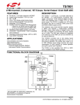
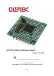
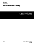
ADC12_A Operation
www.ti.com
Start
Sampling
Stop
Sampling
Start
Conversion
Conversion
Complete
SHI
13 × ADC12CLK
SAMPCON
tsample
tconvert
tsync
ADC12CLK
Figure 17-4. Pulse Sample Mode
17.2.5.3 Sample Timing Considerations
When SAMPCON = 0, all Ax inputs are high impedance. When SAMPCON = 1, the selected Ax input can
be modeled as an RC low-pass filter during the sampling time tsample (see Figure 17-5). An internal MUX-on
input resistance RI (maximum 1.8 kΩ) in series with capacitor CI (25 pF maximum) is seen by the source.
The capacitor CI voltage VC must be charged to within one-half LSB of the source voltage VS for an
accurate n-bit conversion, where n is the bits of resolution required.
MSP430
RS
VS
VI
RI
VC
CI
VI = Input voltage at pin Ax
VS = External source voltage
RS = External source resistance
RI = Internal MUX-on input resistance
CI = Input capacitance
VC = Capacitance-charging voltage
Figure 17-5. Analog Input Equivalent Circuit
The resistance of the source RS and RI affect tsample. The following equation can be used to calculate the
minimum sampling time tsample for a n-bit conversion, where n equals the bits of resolution:
tsample > (RS + RI) × ln(2n+1) × CI + 800 ns
Substituting the values for RI and CI given above, the equation becomes:
tsample > (RS + 1.8 kΩ) × ln(2n+1) × 25 pF + 800 ns
For example, for 12-bit resolution, if RS is 10 kΩ, tsample must be greater than 3.46 ms.
SLAU208F – June 2008 – Revised March 2010
Submit Documentation Feedback
ADC12_A
Copyright © 2008–2010, Texas Instruments Incorporated
437