1
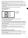
704715 / 01
05 / 2010
Operating instructions
(Ex protection related part) for temperature sensors TS502A, TS522A
according to EU directive 94/9/EC annex VIII (ATEX) group II, equipment
category 3D / 3G
UK
Remarks for safe use in hazardous areas
Functions and features
This sensor is used for temperature measurement and is intended for industrial plants.
The technical data on the type label must be absolutely adhered to. The documentation
must be observed. For applications in which the failure of the sensor may lead to a risk for
persons corresponding safety measures must be provided.
• Use in hazardous areas according to the classification
II 3D (group II, category 3D, apparatus for dust atmosphere).
• The requirements of the standards EN 61241-1 and EN 61241-0 are met.
• Marking
II 3D Ex tD A22 IP67 T 135 °C X
• Use in hazardous areas according to the classification
II 3G (group II, category 3G, apparatus for gas atmosphere).
• The requirements of the standards EN 60079-0 and EN 60079-15 are met.
• Marking
II 3G Ex nA T4 X
• Permissible operating temperature of the application (proper usage):
-20 °C...+115 °C
Installation / Set-up
The units / sensors must only be installed, connected and set up by qualified staff. The
qualified staff must have knowledge of protection classes, regulations and provisions for
apparatus in hazardous areas.
Check whether the classification (see "Marking" above and marking on the unit) is suitable
for the application.
There must be no explosive atmosphere present during any task such as transport, storage,
mounting, electrical connection, commissioning, maintenance or repair.
Installation remarks / Installation
The temperature sensors must be tightly, firmly and safely connected to the measuring
application according to the current state of technology.
• Adhere to the respective national regulations and provisions as well as the relevant installation regulations.
• The sensor must be firmly and safely connected to its evaluation electronics to ensure a
permanent electrical connection.
• The cable must be effectively protected against damage. Abrasion or sharp-edged objects
might damage the cable. This can lead to failure of the unit or make ATEX-conform operation impossible.
• The cable is intended for fixed laying. Minimum bending radius: 15 x cable diameter.
2
• The cable must not be bent or folded at the outlet of the metal sensor housing.
• Earthing of the metal sensing head is made via the metal machine chassis which is connected to the sensor.
• The sensor must be installed so that no twisting forces can act on the cable or sensor.
• The connection cable of the sensor must only be connected to power supplies for passive
resistance sensors, intended and approved for the operation of the installation according
to DIN EN 60751.
• The electrical characteristic values of the unit must not be exceeded.
Max. operating voltage: 6 V
UK
Max. operating current: 10 mA
Max. Power: 20 mW.
• Wiring:
Core colours:
RD
WH = white
RD = red
RD
WH
WH
•
•
•
•
•
Avoid electrostatic charging on units and cables.
To avoid electrostatic charging clean the sensor with a damp cloth only.
Do not mount the sensor in the dust flow.
Avoid dust deposits on the sensors.
In any case the user must check whether the supplied fixing accessories are appropriate
for the corresponding application with respect to the ATEX requirements. The supplied
fixing accessories are not to be considered as a recommendation by the manufacturer for
ATEX-conform installation.
• Steps must be taken to ensure the equalisation of potential of metal parts (housing and
fixing accessories).
• Note on the installation in dust atmosphere according to classification II 3D:
The end of the cable must be protected against the ingress of dust or be outside the
hazardous area.
Special conditions for safe operation
• The cable must not be subject to tensile strain of more than 50 newton.
• Between the cable and the metal housing of the sensor no tensile strain of more than 50
newton must be applied.
• Units or sensors without direct earthing must be installed in an earthed metallic system
ensuring a permanent electrical connection, and so indirectly earthed.
3
Maintenance / Repair
The unit must not be modified nor can it be repaired. In case of a fault please contact the
manufacturer.
The data sheets and the EC declaration of conformity are available from the manufacturer
on request.
4