1
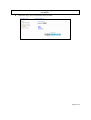
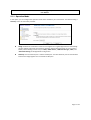
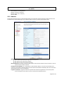
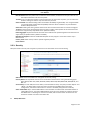
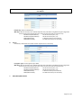
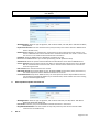
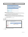
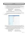
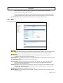
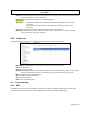
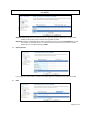
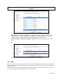
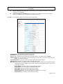
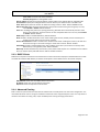
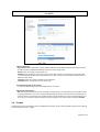
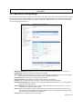
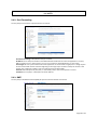
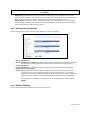
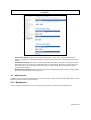
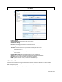
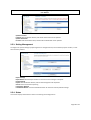
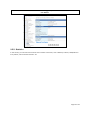
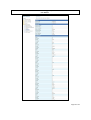
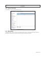
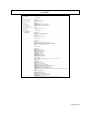
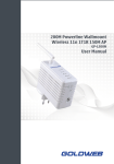
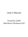
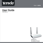
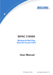
3G Wireless 802.11b/g/n AP/Router
User Manual
3G Wireless 802.11b/g/n AP/Router
User Manual
NOTICE
Changes or modifications to the equipment, which are not approved by the party responsible for compliance,
could affect the user's authority to operate the equipment. Company has an on-going policy of upgrading its
products and it may be possible that information in this document is not up-to-date. Please check with your local
distributors for the latest information.
COPYRIGHT
2009 All Rights Reserved.
No part of this document can be copied or reproduced in any form without written consent from the company.
Trademarks:
All trade names and trademarks are the properties of their respective companies.
REVISION HISTORY
Rev.
0.1
Changes
Initial release
Date
September 06, 2010
Page 2 of 34
3G Wireless 802.11b/g/n AP/Router
User Manual
1. GETTING START
The WLAN Broadband CPE is delivered with the following factory default parameters on the Ethernet LAN interfaces.
Default IP Address: 10.10.10.254
Default IP subnet mask: 255.255.255.0
WEB login User Name: admin
WEB login Password: admin
The device has four operation modes (Bridge /Gateway/WISP /AP Client). The default IP addresses for the device are
10.10.10.254, so you need to make sure the IP address of your PC is in the same subnet as the device, such as
10.10.10.X.
It will take about 25 seconds to complete the boot up sequence after power on.
Prepare your PC to configure the WLAN Broadband CPE
For OS of Microsoft Windows 95/ 98/ Me:
A. Click the Start button and select Settings, then click Control Panel. The Control Panel window will
appear.
Note: Windows Me users may not see the Network control panel. If so, select View all Control
Panel options on the left side of the window.
B. Move mouse and double-click the right button on Network icon. The Network window will appear.
C. Check the installed list of Network Components. If TCP/IP is not installed, click the Add button to
install it; otherwise go to step 6.
D. Select Protocol in the Network Component Type dialog box and click Add button
E. Select TCP/IP in Microsoft of Select Network Protocol dialog box then click OK button to install the
TCP/IP protocol, it may need the Microsoft Windows CD to complete the installation. Close and go
back to Network dialog box after the TCP/IP installation.
F. Select TCP/IP and click the properties button on the Network dialog box.
G. Select Specify an IP address and type in values as following example.
IP Address: 10.10.10.1, (any IP address within 10.10.10.1 to 10.10.10.253 is good to
connect the Wireless LAN Access Point).
IP Subnet Mask: 255.255.255.0
H. Click OK and reboot your PC after completes the IP parameters setting
For OS of Microsoft Windows 2000, XP:
1. Click the Start button and select Settings, then click Control Panel. The Control Panel window will
appear.
2. Move mouse and double-click the right button on Network and Dial-up Connections icon. Move
mouse and double-click the Local Area Connection icon. The Local Area Connection window will
appear. Click Properties button in the Local Area Connection window
3. Check the installed list of Network Components. If TCP/IP is not installed, click the Add button to
install it; otherwise go to step 6.
4. Select Protocol in the Network Component Type dialog box and click Add button.
5. Select TCP/IP in Microsoft of Select Network Protocol dialog box then click OK button to install
the TCP/IP protocol, it may need the Microsoft Windows CD to complete the installation. Close
and go back to Network dialog box after the TCP/IP installation.
Page 3 of 34
3G Wireless 802.11b/g/n AP/Router
User Manual
6.
7.
8.
Select TCP/IP and click the properties button on the Network dialog box.
Select Specify an IP address and type in values as following example.
IP Address: 10.10.10.1, (any IP address within 10.10.10.1 to 10.10.10.253 is good to
connect the Wireless LAN Access Point).
IP Subnet Mask: 255.255.255.0.
Click OK to complete the IP parameters setting.
For OS of Microsoft Windows NT:
1. Click the Start button and select Settings, then click Control Panel. The Control Panel window will
appear.
2. Move mouse and double-click the right button on Network icon. The Network window will appear.
Click Protocol tab from the Network window.
3. Check the installed list of Network Protocol window. If TCP/IP is not installed, click the Add button
to install it; otherwise go to step 6.
4. Select Protocol in the Network Component Type dialog box and click Add button.
5. Select TCP/IP in Microsoft of Select Network Protocol dialog box then click OK button to install
the TCP/IP protocol, it may need the Microsoft Windows CD to complete the installation. Close
and go back to Network dialog box after the TCP/IP installation.
6. Select TCP/IP and click the properties button on the Network dialog box.
7. Select Specify an IP address and type in values as following example.
IP Address: 10.10.10.1, any IP address within 10.10.10.1 to 10.10.10.253 is good to connect
the Wireless LAN Access Point.
IP Subnet Mask: 255.255.255.0
8. Click OK to complete the IP parameters setting
For OS of Microsoft Windows Vista and Windows 7
1.
Click Start Button and select Control Panel, the Control Panel windows pop up.
2.
From Network and Internet category choose View network status and tasks.
3.
Select Change adapter settings, right click Local Area Connection, select Properties
4.
From popup menu in Networking tab select Internet Protocol Version 4 (TCP/IPv4) then click
Properties.
5.
Check Use the following IP address then Specify IP address as following example.
Enter your IP Address; the IP Address can be any number within the range from 10.10.10.1
to 10.10.10.253.
IP Subnet Mask: 255.255.255.0
6. Click OK to complete the IP parameters setting.
Page 4 of 34
3G Wireless 802.11b/g/n AP/Router
User Manual
2. CONFIGURATION OF WEB UTILITY
The Wireless CPE implements a Web utility allowing user to manage the operation via a user friendly interface.
This Utility provides comprehensive system management scheme, including system configuration, performance
monitoring, system maintenance and administration.
2.1. Access Web Utility
To access the Web Utility, you have to launch your Internet Browser. (i.e., MS. IE 5.0 or later, Netscape Navigator
4.7 or later).
Step1: Enter Wireless Router’s default IP address as http://10.10.10.254 in the Address field then
press Enter.
Step2: Login dialog box will appear, enter admin as Administrator Name and admin as default
administrator password, and then click “Login” to access configuration utility.
-
Page 5 of 34
3G Wireless 802.11b/g/n AP/Router
User Manual
Step3: After log in, you can see the Main menu as below.
Page 6 of 34
3G Wireless 802.11b/g/n AP/Router
User Manual
2.1.1. Operation Mode
In this option, you can configure the operation mode which suitable for your environment. The default setting is
Gateway. There are two modes provided:
Bridge: All Ethernet and wireless interfaces are bridged into a single bridge interface. When Bridge
mode is applied, there have some functions change in Internet Settings section. As you can see in
below, Internet Settings section only has “LAN”, “DHCP Client”, “VPN Pass-through”, “DNS”, and
“Advanced Routing” for Bridge Mode’s configuration.
Gateway: The first Ethernet port is treated as WAN port. The other Ethernet ports and the wireless
interface are bridge together and are treated as LAN ports.
Page 7 of 34
3G Wireless 802.11b/g/n AP/Router
User Manual
2.2. Wireless Settings
2.2.1. Basic
You could configure the minimum number of Wireless settings for communication, such as Network name (SSID)
and Channel. The Access Point can be set simply with only minimum setting items.
Radio On/Off: Click button to turn on or turn off radio.
Network Mode: Select 11b/g mixed, 11b only, 11g only, or 11b/g/n mixed mode from the pull-down menu.
(Default is 11b/g/n mixed mode.)
Network Name (SSID): A SSID is referred to a network name because essentially it is a name that identifies a
wireless network.
Multiple SSID 1~7: A multiple SSID is referred to a network name.
Broadcast Network Name (SSID): Enable: This wireless AP will broadcast its SSID to stations.
Disable: This wireless AP will not broadcast its SSID to stations. If stations want to
connect to this wireless AP, this AP’s SSID should be known in advance to make a
connection.
Page 8 of 34
3G Wireless 802.11b/g/n AP/Router
User Manual
AP Isolation: Click enable to isolates all wireless clients and wireless devices on your network from each other; or
click disable to turn off this function.
MBSSID AP Isolation: Click enable or disable AP isolation for multiple SSID.
BSSID: Shows the MAC address of the Wireless Router.
Frequency (Channel): Select channel number or Auto from the pull-down menu.
HT Physical Mode
Operating Mode: Mixed Mode work in 802.11b/g/n mode; Green Field operates only in 802.11n mode and will not
compatible to legacy mode (802.11b/g mode).
Channel Band Width: Select 20 or 20/40. (Default setting is 20/40.)
Guard Interval: Select Long or Auto Guard Interval. (Default setting is Auto.)
MCS: Select form the pull-down menu 0~15, 32 or Auto. (Default setting is Auto.)
Reverse Direction Grant (RDG): When Reverse Direction Grant is enabled, the 3G Mobile Wireless Router can
reduce the transmitted data packet collision by using the reverse direction protocol. During TXOP (Transmission
Opportunity) period, the receiver could use remaining transmission time to transmit data to a sender. The RDG
improves transmission performance and scalability in a wireless environment. (Default: Enabled)
Space Time Block Coding (STBC): A mechanism that allows a unit with only one antenna to leverage multiple
antennas on other 802.11n devices to improve performance and range. (Default: Enabled)
Extension Channel: The “20/40” bandwidth mode uses 5 channels. For example, selecting channel 7 and you can
select 3 or 11 for extension channel. Choose the unused channel for the extension channel.
Aggregation MSDU (A-MSDU): The multiple HT packets can be transmitted with single ACK reply packet. Enable it
to apply this function and reduce the network congestion.
Auto Block ACK: It is another aggregation technique which prevents sending ACK in the communication to reduce
the network congestion. If this option is enabled, the device will try to activate this function when transmitting
massive data.
Decline BA Request: Enable this option to decline the Block ACK request addressed by the other devices.
HT Disallow TKIP: Prevents the use of TKIP data encryption when using 802.11n high-througput data rates.
(Default: Enabled)
Other
HT TxStream: Select the number of transmitter stream.
HT RxStream: Select the number of receiver stream.
The table below shows the relationship among PHY data rate, Bandwidth and Guard Interval.
MCS
Bandwidth = 20MHz
Bandwidth = 40MHz
Short Guard Interval Long Guard Interval Short Guard Interval Long Guard Interval
0 (1S)
7.2
6.5
15
13.5
1
14.4
13
30
27
2
21.7
19.5
45
40.5
3
28.9
26
60
54
4
43.3
39
90
81
5
57.8
52
120
108
6
65
58.5
135
121.5
7
72.2
65
150
135
8 (2S)
14.4
13
30
27
9
28.9
26
60
54
10
43.3
39
90
81
11
57.8
52
120
108
12
86.7
78
180
162
13
115.6
104
240
216
14
130
117
270
243
15
144.4
130
300
270
32
Not Supported
Not Supported
6.7
6
Page 9 of 34
3G Wireless 802.11b/g/n AP/Router
User Manual
MCS: Modulation Coding Scheme
MCS=0~7 (1S, One Tx Stream)
MCS=8~15 (2S, Two Tx Stream)
MCS 32: BPSK
2.2.2. Advance
Use the Advanced Setup page to make detailed settings for the Wireless. Advanced Setup includes items that are
available from the Basic Setup page, such as Beacon Interval, Control Tx Rates and Basic Data Rates.
B/G Protection: User can choose from Auto, On, and Off
Auto: STA will dynamically change as AP announcement
ON: Always send frame with protection.
Off: Always send frame without protection.
Beacon Interval: The interval of time that this wireless access point broadcast a beacon. Beacon is used to
synchronize the wireless network.
Data Beacon Rate (DTIM): This is the Delivery Traffic Indication Map. It is used to alert the clients that
multicast and broadcast packets buffered at the AP will be transmitted immediately after the transmission
of this beacon frame. You can change the
Fragment Threshold: "Fragment Threshold" specifies the maximum fragmentation size of data packet
to be transmitted. If this value is too low, it will result in bad performance.
Page 10 of 34
3G Wireless 802.11b/g/n AP/Router
User Manual
RTS Threshold: When the packet size is smaller the RTS threshold, the wireless access point will not use
the RTS/CTS mechanism to send this packet.
Tx Power: You can adjust the wireless transmit power here. By reduce the TX power; you can reduce the
wireless coverage to make it only cover the area you need.
Short Preamble: The default setting of Short Preamble is disabled (Long Preamble). The “Long Preamble”
can provide better wireless LAN compatibility while the “Short Preamble” can provide better
wireless LAN performance.
Short Slot: Enabling this setting reduces the slot time from standard slot time thus increase throughput.
TX Burst: A performance enhancement that transmits a number of data packets at the same time when
the feature is supported by compatible clients. (Default: Enabled)
Packet Aggregate: A performance enhancement that combines data packets together when the feature is
supported by compatible clients. (Default: Enabled)
IEEE 802.11H Support: Enable or disable 802.11h (DFS and TPC) support. This function works only in
802.11a band.
Country Code: Select country code for specific regulatory domain.
Carrier Detect:
2.2.3. Security
Setup the wireless security and encryption to prevent from unauthorized access and monitoring.
SSID choice: Choose the ESSID to be configured the security setting.
Security Mode: Security Mode: Choose one as the wireless authentication among the following types:
Open Shared, WEP Auto, WPA, WPA-PSK, WPA2, WPA2-PSK, WPA/WPA2-PSK, WPA/WPA2, and
802.1 X.
Access Policy: For each SSID, the Access Policy can be selected and setup. The policy includes “Reject” and
“Allow”. The Reject policy rejects the station according to the MAC table in the policy
configuration, and let the other stations to connect. The allow policy performs reversely.
Add a station MAC: Key in station MAC Address in the text field. The valid format of the MAC Address is
“00:11:6B:11:12:13”. The station MAC Address can be found on the label or configure utility of
the WLAN card. For deleting one record in the table, click the “Del” button of the record. The
maximum number of record on the table is 64.
A.
OPEN/ WEP AUTO
Page 11 of 34
3G Wireless 802.11b/g/n AP/Router
User Manual
Default Key: Select the default key.
WEP Key 1~4: Enter the key in the selected key field. Only valid when using WEP encryption algorithm.
The key must match with the AP’s key. There are several formats to enter the keys.
Hexadecimal (WEP 64 bits):
10 Hex characters (0~9, a~f).
Hexadecimal (WEP 128 bits):
26 Hex characters (0~9, a~f)
ASCII (WEP 64 bits):
5 ASCII characters (case-sensitive).
ASCII (WEP 128 bits):
13 ASCII characters (case-sensitive).
B.
Shared
Shared key is when both the sender and the recipient share a secret key.
Encryption Type: The encryption type is WEP
WEP Key 1~4: Enter the key in the selected key field. Only valid when using WEP encryption algorithm.
The key must match with the AP’s key. There are several formats to enter the keys.
Hexadecimal (WEP 64 bits):
10 Hex characters (0~9, a~f).
Hexadecimal (WEP 128 bits):
26 Hex characters (0~9, a~f)
ASCII (WEP 64 bits):
5 ASCII characters (case-sensitive).
ASCII (WEP 128 bits):
13 ASCII characters (case-sensitive).
C.
WPA/WPA2/WPA1 WPA2
Page 12 of 34
3G Wireless 802.11b/g/n AP/Router
User Manual
WPA Algorithms: Select the type of algorithm, TKIP or AES for WPA, and TKIP, AES or TKIP AES for WPA2,
WPA1/WPA2.
Key Renewal Interval: Enter the renewal security time (seconds) in the column. Default is 3600 seconds.
Set 0 to disable re-key.
RADIUS Server: RADIUS is an authentication, authorization and accounting client-server protocol. The
client is a Network Access Server that desires to authenticate its links. The server is a server that
has access to a user database with authentication information.
IP Address: Enter the RADIUS Server’s IP Address provided by your ISP.
Port: Enter the RADIUS Server’s port number provided by your ISP. (Default is 1812)
Shared Secret: Enter the password that the Wireless Portable Router shares with the RADIUS Server.
Session Timeout: Session timeout interval is for 802.1x re-authentication setting. Set to zero to disable
802.1x re-authentication service for each session. Session timeout interval unit is second and
must be larger than 60.
Idle Timeout: Enter the idle timeout in the column.
PMK Cache Period: Only valid in WPA2 security. Set WPA2 PMKID cache timeout period, after time out,
the cached key will be deleted. PMK Cache Period unit is minute.
Pre-Authentication: Only valid in WPA2 security. The most important features beyond WPA to become
standardized through 802.11i/WPA2 are pre-authentication, which enables secure fast roaming
without noticeable signal latency.
D.
WPA-PSK/WPA2-PSK/WPA-PSK WPA2-PSK
WPA Algorithms: Select the type of algorithm, TKIP or AES for WP-PSK, and TKIP, AES or TKIP AES for
WPA2-PSK, WPA1 PSK WPA2 PSK.
Pass Phrase: Enter the pass phrase 8~63 ASCII or 64 HEX characters in the column.
Key Renewal Interval: Enter the renewal security time (seconds) in the column. Default is 3600
seconds. Set 0 to disable re-key.
E.
802.1x
Page 13 of 34
3G Wireless 802.11b/g/n AP/Router
User Manual
WEP: Select Disable or Enable to this function.
RADIUS Server: RADIUS is an authentication, authorization and accounting client-server protocol. The
client is a Network Access Server that desires to authenticate its links. The server is a server that
has access to a user database with authentication information.
IP Address: Enter the RADIUS Server’s IP Address provided by your ISP.
Port: Enter the RADIUS Server’s port number provided by your ISP. (The default is 1812.)
Shared Secret: Enter the password that the Wireless Portable Router shares with the RADIUS Server.
Session Timeout: Session timeout interval is for 802.1x re-authentication setting. Set to zero to disable
802.1x re-authentication service for each session. Session timeout interval unit is second and
must be larger than 60.
Idle Timeout: Enter the idle timeout in the column.
2.2.4. WDS
Station Site Survey page can shows information of APs nearby, you can choose one of these APs connecting or
adding it to profile.
A.
WDS Mode: Select the mode from the pull-down menu, Disable, Lazy Mode, Bridge Mode or Repeater
Mode. (Default WDS mode is Disable.)
Lazy Mode
Page 14 of 34
3G Wireless 802.11b/g/n AP/Router
User Manual
Phy Mode: Select CCK (11b mode), OFDM(11g mode), HTMIX(11b/g/n mixed mode) or GREENFIELD(11n
mode) from the pull-down menu. Each AP should be setup to the same Phy mode.
AP1~AP4 Encrypt Type: Users should go to the main web page of the Wireless Portable Router Wireless
settings > Security page to set up security mode under Open, Shared, WEP Auto, WPA, WPA-PSK,
WPA2, WPA2-PSK, WPA-PSK/ WPA2-PSK, WPA/WPA2. Select NONE, WEP, TKIP and AES
encryption type from pull-down menu. (Default encryption type is NONE.)
Encrypt Key: Enter the corresponding encryption keys in the field. Select the type of Open, Shared, WEP
Auto authentication, for WEP encryption.
Hexadecimal (WEP 64 bits):
10 Hex characters (0~9, a~f).
Hexadecimal (WEP 128 bits):
26 Hex characters (0~9, a~f).
ASCII (WEP 64 bits):
5 ASCII characters (case-sensitive).
ASCII (WEP 128 bits):
13 ASCII characters (case-sensitive).
Select the type WPA, WPA-PSK, WPA2, WPA2-PSK, WPA-PSK/ WPA2-PSK, WPA/WPA2
authentication, for TKIP or AES encryption.
If users select TKIP or AES encryption, please enter the password in the Encryption Key column
that must be filled with characters longer than 8 and less than 64 lengths to set up the security.
B.
Bridge Mode
Page 15 of 34
3G Wireless 802.11b/g/n AP/Router
User Manual
Phy Mode: Select CCK (11b mode), OFDM(11g mode), HTMIX(11b/g/n mixed mode) or GREENFIELD(11n
mode) from the pull-down menu. Each AP should be setup to the same Phy mode.
AP1~AP4 Encrypt Type: Users should go to the main web page of the Wireless Portable Router Wireless
settings > Security page to set up security mode under Open, Shared, WEP Auto, WPA, WPA-PSK,
WPA2, WPA2-PSK, WPA-PSK/ WPA2-PSK, WPA/WPA2. Select NONE, WEP, TKIP and AES
encryption type from pull-down menu. (Default encryption type is NONE.)
Encrypt Key: Enter the corresponding encryption keys in the field. Select the type of Open, Shared, WEP
Auto authentication, for WEP encryption.
Hexadecimal (WEP 64 bits):
10 Hex characters (0~9, a~f).
Hexadecimal (WEP 128 bits):
26 Hex characters (0~9, a~f).
ASCII (WEP 64 bits):
5 ASCII characters (case-sensitive).
ASCII (WEP 128 bits):
13 ASCII characters (case-sensitive).
Select the type WPA, WPA-PSK, WPA2, WPA2-PSK, WPA-PSK/ WPA2-PSK, WPA/WPA2
authentication, for TKIP or AES encryption.
If users select TKIP or AES encryption, please enter the password in the Encryption Key column
that must be filled with characters longer than 8 and less than 64 lengths to set up the security.
AP1~AP4 MAC Address: Enter MAC address of each other to make the WDS connection.
C.
Repeater Mode
Phy Mode: Select CCK (11b mode), OFDM(11g mode), HTMIX(11b/g/n mixed mode) or GREENFIELD(11n
mode) from the pull-down menu. Each AP should be setup to the same Phy mode.
AP1~AP4 Encrypt Type: Users should go to the main web page of the Wireless Portable Router Wireless
settings > Security page to set up security mode under Open, Shared, WEP Auto, WPA, WPA-PSK,
WPA2, WPA2-PSK, WPA-PSK/ WPA2-PSK, WPA/WPA2. Select NONE, WEP, TKIP and AES
encryption type from pull-down menu. (Default encryption type is NONE.)
Encrypt Key: Enter the corresponding encryption keys in the field. Select the type of Open, Shared, WEP
Auto authentication, for WEP encryption.
Hexadecimal (WEP 64 bits):
10 Hex characters (0~9, a~f).
Hexadecimal (WEP 128 bits):
26 Hex characters (0~9, a~f).
ASCII (WEP 64 bits):
5 ASCII characters (case-sensitive).
ASCII (WEP 128 bits):
13 ASCII characters (case-sensitive).
Page 16 of 34
3G Wireless 802.11b/g/n AP/Router
User Manual
Select the type WPA, WPA-PSK, WPA2, WPA2-PSK, WPA-PSK/ WPA2-PSK, WPA/WPA2
authentication, for TKIP or AES encryption.
If users select TKIP or AES encryption, please enter the password in the Encryption Key column
that must be filled with characters longer than 8 and less than 64 lengths to set up the security.
AP1~AP4 MAC Address: Enter MAC address of each other to make the WDS connection.
2.2.5. WPS
You can setup security easily by choosing PIN or PBC method to do Wi-Fi Protected setup.
WPS Config
WPS: Select Enable then click Apply to use WPS (Wi-Fi Protected Setup) function, then push physical WPS
button on Wireless Portable Router to make a WPS connection. Default setting is Disable.
WPS Summary
WPS Current Status: After enabling the WPS function, if there is connection the status will show
Configured, otherwise, the status will show Idle.
WPS Configured: Trigger WPS AP to do simple config with WPS Client. If WPS configured, here shows Yes,
otherwise, NO.
WPS SSID: Shows the Wireless Portable Router network name.
WPS Auth Mode: The WPS authentication type supports Open, Shared, WEP Auto, WPA-PSK, WPA2,
WPA2-PSK, WPA-PSK/ WPA2-PSK. Please go to the configuration page Wireless Settings >
Security to set up the WPS security.
WPS Encryp Type: For Open authentication mode, the selection of encryption type are NONE and WEP.
For WPA-PSK, WPA2-PSK and WPA-PSK/ WPA2-PSK authentication mode, the encryption type
supports TKIP, AES and TKIP/AES.
WPS Default Key Index: Shows the WEP default key (1~4).
WPS Key (ASCII): Shows the WPS security keys (ASCII). The key can be used to ensure the security of the
wireless network.
Page 17 of 34
3G Wireless 802.11b/g/n AP/Router
User Manual
AP PIN: Here shows the AP’s PIN code (Personal Identification Number) that the enrollee should enter the
registrar’s PIN code to make a connection.
Reset OOB: Reset WPS AP to the OOB (out-of-box) configuration.
WPS Process
WPS mode:
PIN: Personal Identification Number. Select PIN then click Apply to make a WPS
connection.
PBC: Push Button Communication. Select PBC then click Apply to make a WPS
connection.
PIN: Personal Identification Number. Input Enrollee’s Pin Code to AP-Registrar.
WPS Status: Here shows the current status of the WPS. If there is connection the status shows WSC
Success, otherwise, the status shows Idle.
2.2.6. Station List
The Station Statistics page shows the settings and current operation status of the Station.
MAC Address: The MAC address of the wireless station which connected the AP.
Aid: The association ID.
PSM: The power save mode.
MimoPS: The MIMO power save mode. MIMO, Multiple-input and multiple-output, is the use of multiple
antennas at both the transmitter and receiver to improve communication performance.
MCS: The Modulation and Coding Scheme.
BW: The wireless channel bandwidth.
SGI: Short Guard Interval
STBC: Space-Time Block Coding
2.3. Internet Settings
2.3.1. WAN
The WAN port is the connection of the 802.11n AP Router module to existing broadband device such as Cable
modem or ADSL CPE. Click WAN on Internet Setting, below screen will prompt for WAN setting.
Page 18 of 34
3G Wireless 802.11b/g/n AP/Router
User Manual
WAN Connection Type: Select the WAN Connection Type Static (fixed IP), DHCP (Auto Config), PPPoE
(ADSL) and L2TP, PPTP and 3G. Default setting is DHCP enabled.
MAC Clone: Enable or disable MAC Clone. After enabling this function, click the Fill my MAC button, and
then AP will use this MAC address to communicate with the device that connects to the AP’s
WAN interface. The default setting is Disable
A.
STATIC (fixed IP)
In this page, enter the IP address, subnet mask, default gateway, and DNS server provided by the ISP.
B.
DHCP
Page 19 of 34
3G Wireless 802.11b/g/n AP/Router
User Manual
Select DHCP (Auto config) type of WAN connection, AP will acquires all of the network parameters via
WAN interface, such as the IP address, the subnet mask, the gateway, and the DNS server address.
C.
PPPoE
In this page, enter the username and the password provided by your ISP, and set operation mode to Keep
Alive, On Demand, or Manual.
D.
L2TP
In this page, enter the IP address of L2TP server, the username, and the password provided by ISP. Select
Address Mode to either Static or Dynamic for the WAN addressing type. If Static is selected, set the
IP address, subnet mask, and default gateway. If is Dynamic is selected, the IP address, subnet mask,
and default gateway of WAN interface are automatically assigned by the DHCP server.
Set Operation Mode to Keep Alive, On Demand, or Manual mode to configure timing for connection
redial.
Page 20 of 34
3G Wireless 802.11b/g/n AP/Router
User Manual
In this page, enter IP address of the PPTP server, username, and password provided by ISP. Select
Address Mode to either Static or Dynamic for the WAN addressing type. If Static is selected, set the
IP address, subnet mask, and default gateway. If is Dynamic is selected, the IP address, subnet mask,
and default gateway of WAN interface are automatically assigned by the DHCP server.
Set Operation Mode to Keep Alive, On Demand, or Manual mode to configure timing for connection
redial.
E.
3G
In this page, Select your model of USB 3G modem, Apply for connecting 3G.
2.3.2. LAN
When the module operates in the Gateway mode, it supports the NAT (NAPT) feature. It means the WAN and LAN
interfaces are located in different network segments and therefore the date traffic needs to be routed between
the two interfaces.
To communicate with 802.11n router properly, must assign an IP address to the LAN port of the user’s PC. There
are two ways to assign a proper IP address to the user PC’s LAN port:
Page 21 of 34
3G Wireless 802.11b/g/n AP/Router
User Manual
Manual configuration of the user PC: This required if the user configures the 802.11n router WAN
port with a static IP address.
Dynamic IP assignment with DHCP: 802.11n router can act as a DHCP server which dynamically
assigns an IP address to user’s PC located in the LAN-side network.
Click LAN on Internet Settings, below screen will prompt for LAN setting.
LAN IP Address: The LAN IP address. Default: 10.10.10.254
Subnet Mask: The LAN net-mask. Default: 255.255.255.0
LAN 2: Enable or disable the second IP address of the LAN interface. The default setting is Disable.
LAN 2 IP Address: The second IP address of the LAN interface. This IP address should not collide with the IP
address of the interior network.
LAN 2 Subnet Mask: The subnet mask of the second IP address of the LAN interface.
MAC Address: Display the current MAC address that LAN interface uses.
DHCP Type: Select Disable to disable this Router to distribute IP address. Select Server to enable this Router
to distribute IP addresses (DHCP server). And the following field will be activated for you to enter
this starting IP address.
Start IP Address: The start IP address of the DHCP address pool.
End IP Address: The end IP address of the DHCP address pool.
Subnet Mask: The subnet mask that DHCP server assigns.
Subnet Mask: The subnet mask that DHCP server assigns.
Secondary DNS Server: The secondary DNS server that DHCP server assigns.
Default Gateway: The gateway that DHCP server assigns.
Page 22 of 34
3G Wireless 802.11b/g/n AP/Router
User Manual
Lease Time: The lease time of the IP address.
Statically Assigned: For binding MAC and IP.
Start IP address: Specify the starting IP address of the IP address pool. Default Start IP: 192.168.1.100.
End IP address: Specify the ending IP address of the IP address pool. Default End IP: 192.168.1.250.
Lease Time: Specify the time duration for which the settings will be in effect. Default: 86400 seconds.
802.1d Spanning Tree: It provides redundant link and prevents network from generating loop. You may
select Enable or Disable. Default: Disable.
LLTD: After enabling LLTD (Link Layer Topology Discovery), Windows Vista automatically discovers other
devices’ link topologies, and these devices are also compatible with LLTD. You may select Enable
or Disable. Default: Disable.
IGMP Proxy: Enable or disable IGMP Proxy. Default: Disable.
UPnP: Enable or disable the UPnP function. After enabling this function, AP will provide automatic portmapping for P2P software on the interior network.
Router Advertisement: Enable or disable router advertisement. After enabling this function, APs will send
broadcast message or send back message to show their existence. Default: Disable.
PPPoE Relay: Enable or disable PPPoE Relay. After enabling this function, the local PC can directly make
PPPoE dial-up in the gateway mode. Default: Disable.
DNS Proxy: Enable the DNS Proxy that will relay users’/clients’ DNS requests to a real DNS server IP address.
Users no need to specify real DNS server IP address. Default: Enabled.
2.3.3. DHCP Clients
DHCP client computers connected to the device will have their information displayed in the DHCP Client List table.
The table will show the MAC Address, IP Address and Expired in of the DHCP lease for each client computer.
MAC Address: Shows the client MAC address information.
IP address: Shows the client IP address information.
Expires in: Shows the expired time of the client.
2.3.4. Advanced Routing
Static routes are special routes that the network administrator manually enters into the router configuration. The
route table allows the user to configure and define all the static routes supported by the router. You may add and
remote custom Internet routing rules, and/or enable dynamic routing exchange protocol here.
Page 23 of 34
3G Wireless 802.11b/g/n AP/Router
User Manual
[Add a routing rule]
Destination: Defines the base IP address (Network Number) that will be compared with the destination
IP address (after an AND with NetMask) to see if this is the target route.
Range: select the range from drop down list
Gateway: Enter IP address of the next hop router that will be used to route traffic for this route If this
route is local (defines the locally connected hosts and Type = Host) then this IP address MUST be the IP
Address of the router.
Interface: Select the interface mode from drop down list.
Comment: Enter the comment for this static route.
[Current Routing table in the system]
To see the detail settings of current routing table in the system.
[Dynamic Routing Setting]
RIP: RIP can be used to cache routes learned by routing protocols, thus allowing the automation of static
routing maintenance. The router, using the RIP (Routing Information Protocol) protocol, determines the
network packet’s route based on the fewest number of hops between the source and the destination. In
this case, you could automatically adjust to physical changes in the network layout. Default is Disable.
2.4. Firewall
The Firewall contains the following sections: MAC/IP/Port Filtering, Port Forwarding, DMZ, System Security Setting,
Content Filtering, and Port Trigger
Page 24 of 34
3G Wireless 802.11b/g/n AP/Router
User Manual
2.4.1. MAC/IP/Port Filtering Settings
You can setup firewall rules to protect your network from virus, worm and malicious activity on the internet. Filters
are used to deny or allow LAN computers from access the Internet. Within the local area network, the unit can be
setup to deny Internet access to computers using the assigned IP or MAC addresses. The unit can also block users
from accessing restricted web site.
MAC/IP/Port Filtering: Enable this function, all list from the filtering will be deny the internet access.
Default Policy: There have 2 options, Dropped and Accepted.
MAC Address: The MAC address of the computer in the LAN (Local Area Network) to be used in the MAC
filter table. Enter the MAC address of LAN port, e.g. 00:00:27:88:81:18
Dest IP Address: The IP address that will be denied to access.
Source IP Address: The IP address that will be denied access to the Internet.
Protocol: This is the protocol type that will be used with the Port that will be blocked.
Destination Port Range: The single port or port range that will be denied to access. If no port is specified,
all ports will be denied access.
Source Port Range: The single port or port range that will be denied access to the Internet. If no port is
specified, all ports will be denied access.
Action: Select rules for DROP, or rules for ACCEPT form the pull-down menu. Select Drop to disconnect
with the Wireless Portable Router that MAC address has be set, and ACCEPT to allow the device
that connect with the Wireless Portable Router.
Comment: Key in a description for these settings.
Page 25 of 34
3G Wireless 802.11b/g/n AP/Router
User Manual
2.4.2. Port Forwarding
You may setup virtual servers to provide service on internet.
Virtual Server Setting: Enable/Disable the port forward.
IP Address: This is the port number on the WAN side that will be used to access the application. You may
define a single port or a range of ports. You can use a comma to add multiple ports or port ranges.
Port Range: This is the port used to forward the application. It can be either a single port or a range of ports.
For the TCP and UDP services enter the beginning of the range of port numbers used by the service. If the
service uses a single port number, enter it in both the start and finish fields.
Protocol: Select the protocol (TCP, UDP, or TCP & UDP) used to the remote system or service.
Comment: You may key in a description for the IP address.
2.4.3. DMZ
You may setup a De-Militarized Zone (DMZ) to separate internet network and internet.
Page 26 of 34
3G Wireless 802.11b/g/n AP/Router
User Manual
DMZ Setting: If the DMZ Host Function is enabled, it means that you set up DMZ host at a particular
computer to be exposed to the Internet so that some applications/software, especially Internet/Online
game can have two-way connections. Select Enable or Disable from the pull-down menu.
DMZ IP Address: Enter the IP address of a particular host in your LAN that will receive all the packets
originally going to the WAN port/Public IP address above. Note: You need to give your LAN PC clients a
fixed/static IP address for DMZ to work properly.
2.4.4. System Security Settings
You may configure the system firewall to protect AP/Router itself from attacking.
Remote management
Remote management (via WAN): Select Deny or Allow form the pull-down list to enable or disable the
remote client to control the Wireless Portable Router via WAN. Default setting is Deny.
Ping form WAN Filter
Ping form WAN Filter: Select Disable or Enable from the pull-down list. Default setting is Disable.
Stateful Packet Inspection (SPI)
SPI Firewall: Stateful packet inspection (SPI) is a firewall that keeps track of the state of network
connections (such as TCP streams, UDP communication) traveling across it. The firewall is
programmed to distinguish legitimate packets for different types of connections. Only packets
matching a known connection state will be allowed by the firewall; others will be rejected.
Select Disable or Enable the SPI firewall function from the pull-down list. Default setting is
Disable.
2.4.5. Content Filtering
You can setup content filter to restrict the improper content access.
Page 27 of 34
3G Wireless 802.11b/g/n AP/Router
User Manual
Content Filter Setting: There have three options for this filter – Proxy, Java, and ActiveX.When those
options are checked, the content filter will deny computer from access to the internet by contented those
options.
Web URL Filter Setting: With security reason, the URL Filter provides the enterprise to manage and restrict
employee access to non-business or undesirable content on the Internet. URL Filter is a web solution that
blocks web-sites access according the URL Filter String no matter the URL string is found full or partial
matched with a keyword.
Web Host Filter Settings: Web Host Filter is a web solution that blocks web-sites access according the Web
Host name or partial matched with a keyword.
2.5. Administration
The Administration contains the following sections: Administration, Upload Firmware, Setting Management, Status,
Statistics, System Command, and System Log
2.5.1. Management
You may configure administrator account and password, NTP settings, and Dynamic DNS settings here.
Page 28 of 34
3G Wireless 802.11b/g/n AP/Router
User Manual
Language Setting
Select Language: Select language for web user interface.
Administrator Settings
Account: Setting administrator account name for login.
Password: Setting login password for administrator account.
NTP Settings
Time Zone: Select the time zone of your location from the pull-down menu.
NTP Server: Enter the Network Time Protocol Server here. Ex: time.nist.gov, ntp0.broad.mit.edu, or
time.stdtime.gov.tw.
NTP Synchronization: Enter the hour(s) here to synchronize time of the Wireless Portable Router with the
server selected.
DDNS Settings
Dynamic DNS Provider: Select the DNS provider form the pull-down list.
Account: Enter your account name that you registered in DNS provider website.
Password: Enter your login passwords that you have registered.
DDNS: Apply for a Domain Name, and ensure it is allocated to you.
2.5.2. Upload Firmware
Firmware is the main software image, which the AP Router needs to perform all tasks in real time. Firmware
upgrades are required for adding new features or to resolves bugs. It takes about 1 minute to upload/upgrade
flash and be patient please.
Caution: A corrupted image will hang up the system.
Page 29 of 34
3G Wireless 802.11b/g/n AP/Router
User Manual
Update Firmware
Location: Click the Browse button; find the file the firmware to be updated.
Update Bootloader
Location: Click the Browse button; find the file the bootloader to be updated.
2.5.3. Setting Management
You might save system settings by exporting them to configuration file, restore them by import the file, or reset
them to factory default.
Export Settings
Export Button: Click the Export button to save the current settings to computer.
Import Settings
Import: Click the Browse button, find and the settings file to be imported.
Cancel: Click to discard the importing.
Load Factory Defaults
Load Default Button: Click to Load Default button to recover the factory default settings.
2.5.4. Status
This section displays information of the current settings and configurations
Page 30 of 34
3G Wireless 802.11b/g/n AP/Router
User Manual
2.5.5. Statistics
In this section, you can look at the statistics of this wireless 11n Router, such as Memory statistics, WAN/LAN’s Rx
& Tx packets, and all interface statistics…etc
Page 31 of 34
3G Wireless 802.11b/g/n AP/Router
User Manual
Page 32 of 34
3G Wireless 802.11b/g/n AP/Router
User Manual
2.5.6. System Command
In this section, you can run system command as root.
2.5.7. SDK History
This 802.11n Router supports sending system log (sending UDP packets and keeping log messages in Log Server.
Click Refresh on Administration, below screen will prompt for System Log information
Page 33 of 34
3G Wireless 802.11b/g/n AP/Router
User Manual
Page 34 of 34