1
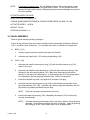
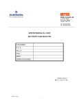
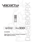
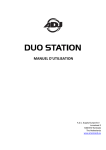
Bettis Canada Ltd.
4112 91A Street
Edmonton, Alberta, Canada T6E 5V2
Tel: (403) 450-3600
Fax: (403) 450-1400
Edmonton
SERVICE MANUAL No. I-0052
3" ANSI 600
MULTIPORT SELECTOR VALVE
WITH HIGH DIFFERENTIAL PRESSURE SEAL
CUSTOMER:
P.O.#:
W.O.#:
TAG:
DATE:
APPLIES TO OPERATOR MODEL:
DESCRIPTION
DWG.NO
PAGE
I
INTRODUCTION . . . . . . . . . . . . . . . . . . . . . . . . . . . . . . . . . . . . . . . . . . . . . . . . . . . . . . . . .
2
II
VALVE SPECIFICATIONS . . . . . . . . . . . . . . . . . . . . . . . . . . . . . . . . . . . . . . . . . . . . . . . . .
2
III
VALVE ASSEMBLY . . . . . . . . . . . . . . . . . . . . . . . . . . . . . . . . . . . . . . . . . . . . . . . . . . . . . . .
3
IV
VALVE DISASSEMBLY . . . . . . . . . . . . . . . . . . . . . . . . . . . . . . . . . . . . . . . . . . . . . . . . . . . .
5
TYPICAL VALVE ASSEMBLY DRAWING . . . . . . . . . . . . . . . . . . . . . . . AB0230-30 . . . . .
6
V
ACTUATOR ASSEMBLY . . . . . . . . . . . . . . . . . . . . . . . . . . . . . . . . . . . . . . . . . . . . . . . . . . .
7
VI
CAM ADJUSTING . . . . . . . . . . . . . . . . . . . . . . . . . . . . . . . . . . . . . . . . . . . . . . . . . . . . . . . .
8
SWITCHPAK ASSEMBLY DRAWING . . . . . . . . . . . . . . . . . . . . . . . . . . IB0048-08 . . . . .
11
VII
VALVE INSTALLATION . . . . . . . . . . . . . . . . . . . . . . . . . . . . . . . . . . . . . . . . . . . . . . . . . . . .
12
VIII
VALVE MAINTENANCE . . . . . . . . . . . . . . . . . . . . . . . . . . . . . . . . . . . . . . . . . . . . . . . . . . .
12
IX
TROUBLESHOOTING . . . . . . . . . . . . . . . . . . . . . . . . . . . . . . . . . . . . . . . . . . . . . . . . . . . . .
13
TYPICAL WIRING DIAGRAM . . . . . . . . . . . . . . . . . . . . . . . . . . . . . . . . SB0704-X01 . . . .
14
NOTES . . . . . . . . . . . . . . . . . . . . . . . . . . . . . . . . . . . . . . . . . . . . . . . . . . . . . . . . . . . . . . . .
15
X
I-0052--.WPD/1
ORIG:JUL-31-97
I
INTRODUCTION
As many as eight flow lines can be manifolded through one Bettis Multiport Selector Valve.
The valve allows diversion of an individual flow-line to a test outlet for testing or sampling, while
combining the flow of the other seven into a separate group outlet.
II VALVE SPECIFICATIONS
RATING
TRIM
SIZE
MAXIMUM
WORKING
PRESSURE
PSIG
WORKING
TEMP
bC
STD.
740
38
HIGH
TEMP
600
260
RATING
TRIM
ANSI 300RF CONNECTION
NPS
3x6
SIZE
MAXIMUM
WORKING
PRESSURE
PSIG
WORKING
TEMP
bC
STD.
1440
38
HIGH
TEMP
1200
260
EIGHT
FLOWLIN
E
INLET
PORTS
ONE
TEST
OUTLET
PORT
ONE
GROUP
OUTLET
PORT
VALVE
NPS 3
NPS 3
NPS 6
800
ANSI 600RF CONNECTION
NPS
3x6
WEIGHT
lbs.
WEIGHT
EIGHT
FLOWLIN
E
INLET
PORTS
ONE
TEST
OUTLET
PORT
ONE
GROUP
OUTLET
PORT
VALVE
NPS 3
NPS 3
NPS 6
860
lbs.
Cv = 151 FOR TEST OUTLET FLOW
Cv = 369 FOR GROUP OUTLET FLOW
SHELL HYDROSTATIC TEST PRESSURE = 2160 PSIG (14900 kPa)
STANDARD TRIM
MAXIMUM DIFFERENTIAL: TEST - GROUP = 300 PSIG (2070 kPa)
MAXIMUM DIFFERENTIAL: GROUP - TEST = 250 PSIG (1720 kPa)
HIGH TEMPERATURE TRIM
MAXIMUM DIFFERENTIAL: TEST - GROUP = 400 PSIG (2760 kPa)
MAXIMUM DIFFERENTIAL: GROUP - TEST = 350 PSIG (2415 kPa)
INTERMITTENT SEAL EXPOSURE AT 285bC FOR 15 MINUTES WITH MAXIMUM BODY
PRESSURE OF 1100 PSIG AND MAXIMUM DIFFERENTIAL.
STATIC STATIONARY DIFFERENTIAL: TEST - GROUP 1000 PSID FOR 15 MINUTES @ 40bC
STATIC STATIONARY DIFFERENTIAL: GROUP - TEST 500 PSID FOR 15 MINUTES @ 40bC
(I-0052--.wpd)
2
NOTE:
In emergency situations only, the 3x6 Multiport Selector Valve can maintain a static
stationary differential pressure per specifications above. Do not operate the motor
operator at higher than maximum differential pressure because damage may result to
the motor operator.
ACTUATOR SPECIFICATIONS
PLUG POSITION TOLERANCE: ±2b
TORQUE @ MAXIMUM DIFFERENTIAL SHOULD BE BETWEEN 100 AND 170 ft.lbs.
ACTUATOR SPEED: 1.4 RPM
WEIGHT: 130 lbs.
POSITION ACCURACY: ±1b
III VALVE ASSEMBLY
Refer to typical assembly drawing on page 6.
Ensure all the parts are clean and in good condition before assembling the Multiport Selector
Valve. Use Esso Valve Grease No. 1, or a suitable equivalent, to lubricate the components.
A.
B.
BODY: (110)
1.
Visually inspect internal and external surfaces and threads.
2.
Lubricate and install teflon / 25% carbon plug bushing (120).
PLUG: (130)
1.
Lubricate and install the lower plug o-ring (133) with the teflon backup ring (136)
"above" the o-ring.
2.
Lubricate and install the seal adjusting nut (138) with three seal wave springs (140)
followed by the wave spring backup (143). Make sure these springs are placed
properly on the step of the adjusting nut. If these springs are not in the proper place,
it is impossible to get the plug seal assembly (145, 146) to hold pressure.
3.
Install the seal back-up plate (143) against its' shoulder in the plug.
4.
Lubricate and place the plug seal o-ring (149) on the stainless steel portion of the
plug seal assembly (145, 146). Lubricate and install the plug seal assembly, with the
plug seal o-ring properly positioned into the plug.
NOTE:
5.
Install one scraper wave spring (158), followed by the scraper (154), into the plug
over the seal assembly.
NOTE:
(I-0052--.wpd)
Push seal into plug's seat pocket by hand only.
Lubricate the spring and scraper so they can stay in place in the plug during
assembly. Ensure that the scraper fits freely in the plug. Check by pushing
and letting go to see if the scraper returns to its original position.
3
C.
6.
Lower the plug (130) assembly vertically into the body ensuring that the plug seal
and scraper clear the body bore. When installed the plug assembly rests on top of
the bushing.
7.
Install and grease the tapered bearing cone (160) and rollers onto the plug.
BONNET: (162)
1.
Lubricate and install the bearing cup (160) inside the bonnet.
2.
Lubricate and install the o-ring (167) and the teflon backup ring (170) in the I.D.
groove.
NOTE:
Backup ring (170) is above o-ring (167) when the bonnet is installed on the
body.
3.
Lubricate and install the o-ring (173) in the outer groove.
4.
Install the wiper (171) and the grease nipple (178).
NOTE:
5.
Grease to flush and fill passage at this time.
Set the bonnet in place with the actuator mounting holes straddling centerline of the
"group outlet" port, ensuring that the bonnet is placed flat on top of the valve body to
prevent damaging the o-ring (167). Place bonnet such that 1/2 NPT is located over
group outlet.
NOTE:
Push bonnet down into the body by hand or by using rubber mallet.
6.
Install studs (180) with anti-seize lubricant C5-A high-temp copper compound, or a
suitable equivalent.
7.
Tighten two of the sixteen bonnet nuts (182) at a 180b interval, then ensure that the
plug (130) rotates freely through a complete revolution.
8.
Tighten the remaining nuts after confirming bonnet (162) and plug (130) have been
centred. Torque the nuts to 250 ft.lbs.
9.
Adjust the plug seal assembly (145, 146), by first aligning the plug (130) with an open
(ie. home test) port, then turn the adjusting nut (138) counter clockwise, viewing
towards the plug centerline, with adjusting tool until the scraper (154) just touches
the inside wall surface.
10. Rotate plug (130) at least one revolution and check for binding or excessive turning
torque (ie. it should be 7 to 10 ft.lbs), then tighten the adjusting nut (138) with the
supplied adjusting tool counter clockwise, viewing towards the plug centerline, to 35
ft.lbs. of torque.
NOTE:
(I-0052--.wpd)
Do not over tighten the adjusting nut (138) as damage to the seal assembly
may result.
4
11. Turn the plug (130) at least one revolution and check for smooth movement. If plug
seal assembly (145, 146) is binding at each port when plug (130) is rotating, that
means either the plug seal or the wave springs (140) are not in the proper position.
See disassembly procedure below, if required.
12. Install vent plug (176) in the bonnet port.
13. Perform any required leakage test(s).
IV VALVE DISASSEMBLY
Refer to typical valve assembly drawing on page 6.
1.
Release the pressure to zero before proceeding.
2.
Remove plug or fitting from port for access and turn the seal adjusting nut (138) clockwise
to release load on plug seal assembly (145, 146) and scraper (154) to clear body bore.
3.
Remove the sixteen bonnet nuts (182) and studs (180). Remove the bonnet (162) with a
straight lift along axis.
NOTE:
4.
Bonnet has two tapped holes that can be used for lifting.
Remove the plug (130) from the valve body (110).
(I-0052--.wpd)
5
V
ACTUATOR ASSEMBLY
A.
PEDESTAL, CONNECTOR, SPEED REDUCER AND MOTOR
Refer to typical assembly drawing on page 6.
1.
Set the speed reducer pedestal (400) in place.
2.
Install two bolts (404), two lockwashers (406), two spacers (401), two studs (403),
and four nuts (405) with indicator plate (402).
3.
Install the lower connector (408).
4.
Install the indicator (188) on the upper connector (410).
5.
Install the upper connector (410) with setscrew (415) started, but without the
connector bolt and locknut.
6.
Install the speed reducer (426) with key (418) and four bolts (432), lockwashers (436)
and nuts (434).
7.
Check for free rotation between connector halves to confirm shaft alignment. Adjust
if necessary.
8.
Tighten above mounting bolts and nuts.
9.
Install and tighten the lower connector bolt (412) and locknut and tighten the
setscrew (415).
10. Install the motor (438) with four bolts and lockwashers. Align and tighten.
B.
LOCAL STEPPING COMMAND ELECTRICAL CONDUIT, SWITCHPAK PEDESTAL
AND CONNECTOR
Refer to the Switchpak assembly drawing on page 11.
1.
Set the Switchpak pedestal (449) in place and install four studs (452), four
flatwashers (455), four lockwashers (453) and four nuts (454).
2.
Install the Switchpak connector (457) on the speed reducer shaft, followed by the
Switchpak coupling (455) and the Switchpak coupling adapter.
3.
Off of the Switchpak pedestal, assemble the Switchpak (300), 1 NPT x 3/4 NPT
reducer (322), two 3/4 NPT close nipples (310), seal encloser (315), seal cover (314)
and the junction box (370).
4.
Position the Switchpak and junction box assembly on the pedestal using the spacers
(371), bolts (372), lockwashers (374) and nuts (373), engaging the Switchpak
coupling adapter.
5.
Install the four Switchpak bolts (458) and lockwashers (462).
(I-0052--.wpd)
7
6.
Off the Switchpak pedestal assemble the push button station (350), local/remote
switch (355), jog push button (356), 3/4 NPT capped elbow (321), 3/4 NPT x 2.50
long nipple (317) and 3/4 NPT x 3.00 long nipple (318). Thread into the seal encloser
until the back of the push button station is flush with the Switchpak pedestal. Loosely
install the push button station bolts (351), lockwashers (354) and nuts.
7.
Between the motor terminal box (438) and the seal encloser, install one 3/4 NPT
close nipple (310), one 3/4 NPT x 3.00 long nipple (318), one 3/4 NPT x 3.25 long
nipple (311), one 3/4 NPT x 3.50 long nipple (312), two 3/4 NPT capped elbows
(321), and the 3/4 NPT union (320).
8.
Install all wiring according to the electrical diagram and local regulations.
9.
Check shaft alignment by rotating both shafts independently, without binding
occurring in the connector. Adjust if necessary.
10.
With the Switchpak relay bracket and push button station aligned on the Switchpak
pedestal, tighten all mounting bolts, nuts and setscrews.
VI CAM ADJUSTING
Refer to the Switchpak assembly drawing on page 11, and the typical wiring diagram on page
14.
A.
Objective:
B.
Pre-requisites
To align valve plug (130) at each port upon application of command signal
to electric actuator.
1.
Switchpak is assembled and installed according to factory specifications.
2.
Typical wiring and controls are according to wiring diagram on page 14, and the eight
on/off command switches and main on/off switch (disconnect means) are in place.
3.
Power supply is present.
4.
Connections
a)
Terminals 13 and 14 connect 110 VAC electrical supply.
b)
Terminals 11 and 12 connect 24 VDC command electrical supply with the
positive (+) lead to terminal 12.
NOTE:
(I-0052--.wpd)
The negative (-) will be connected to terminals 1 through 8 as the desired
port is selected. The 24 VDC electrical supply should have an ON/OFF
switch to isolate it from the unit while adjustments are being made.
8
C.
Before proceeding with cam adjustment, ensure that:
1.
All port plugs are removed; or indicator is in place accurately, whichever is
applicable, to check for plug (130) and port position.
2.
Cam setscrew (12) is flush with cam (10) and the signal adjuster screw (13) standout
is just sufficient to trigger microswitch (16).
3.
Limit switch No. 1 (lowest on stack) corresponds with Port #1.
NOTE:
D.
If signal adjuster screw (13) standout is excessive, it could damage the
microswitch (16) or lever during rotation. Notice that since cam setscrew (12) is
opposite to signal adjuster screw (13) on each cam, some cams can be preset to
reduce trial and error repetitions.
Cam Adjusting Procedure:
NOTE:
Before locking each cam (10) in place, confirm that signal adjuster screw (13)
standout is just sufficient to actuate microswitch (16).
1.
Close main switch and command switch #1 to start actuator, then open main switch
manually when plug (130) and port #1 are aligned.
2.
Rotate cam #1 until the signal adjuster screw (13) triggers the switch then advance
the cam, radially approximately 1b, to account for the motor and drive train
momentum to preset cam #1.
With the plug (130) still aligned to #1 port, make the following preliminary adjustments:
NOTE:
Opposing ports (180b to each other) can be preset.
i.e. number 4 port is opposite to number 8.
3.
Preset cam #5. Align the trigger screw of cam #5 with the setscrew of cam #1. To
tighten cam #5 setscrew, insert Allen key between the two switch stacks.
4.
Apply power (connect negative to terminal #2, turn switch on and off) and manually
stop at port #2, adjust cam #2 as per step 2 above.
5.
Preset cam #6. Align the trigger screw of cam #6 with the setscrew of cam #2.
Again, to tighten the setscrew, insert the Allen key between the two switch stacks.
6.
Apply power (connect negative to terminal #3, turn switch on and off) and manually
stop at port #3, adjust cam #3 as per step 2 above.
7.
Preset cam #7. Align the trigger screw of cam #7 with the setscrew of cam #3 and
tighten.
(I-0052--.wpd)
9
8.
Apply power (connect negative to terminal #4, turn switch on and off) and manually
stop at port #4. Adjust cam #4 as per step 2 above. Preset cam #8 as per step 3
above.
9.
Continue to activate command switches for remainder of ports, and adjust cams for
over/under travel.
NOTE:
E.
Jog Feature
1.
Select "local setting" on the remote/local switch.
2.
Depress the "JOG" switch and maintain it until the indicator is aligned over the
desired port then release it.
NOTE:
F.
Always open main switch or disconnect power when adjusting or servicing
Switchpak.
When viewed from above, the plug rotates counter-clockwise (CCW) only.
Finally
1.
Pour seal or tag
2.
Install the 1 NPT caplug in the Switchpak.
3.
Install the 1/2 NPT port plugs in the Switchpak.
(I-0052--.wpd)
10
VII VALVE INSTALLATION
Before installing the unit, observe the following:
1.
Check for external physical damage.
2.
Check for any visible leakage of gear oil from the speed reducer (426).
3.
Visually inspect inside valve through group outlet port.
4.
Check the wiring arrangement using the attached diagram on page 14 or as supplied for a
particular order/unit.
5.
Connect power supply and signal circuits to test the plug (130) location and motor (438)
rotation at each port.
NOTE:
6.
The Multiport Selector Valve is factory adjusted when supplied with actuator and
should not require further adjustment.
Connect piping.
NOTE:
When hydrotesting external piping, position the plug between any two inlet ports
in order to equalize test pressure between the valve body and external piping,
and prevent possible seal damage from occurring.
VIII VALVE MAINTENANCE
The Multiport Selector Valve is shipped completely greased and lubricated, but it is
recommended that the unit be checked prior to operation if it has been stored for more than
one year.
1.
Check speed reducer oil at regular intervals, and change the oil each hundred running
hours or once a year, whichever comes first. Use Mobile Synthetic SHC-634 ISO VG460
lubricant or equivalent.
2.
Make sure oil in the speed reducer (426) is at indicated level.
NOTE:
Excessive oil could cause pressure build-up, leakage and overheating which will
result in rapid wear of oil seals, bearing and gears.
3.
Lubricate bearing (160) through grease nipple every six months, or as needed. Use Dow
Corning Extreme High Temp #41 grease, or a suitable equivalent.
4.
Do not lubricate the motor because it is a sealed unit.
(I-0052--.wpd)
12
IX TROUBLESHOOTING
A.
Actuator does not align plug (130) to port.
1.
If alignment is off only at one or two ports but the rest are aligned, then refer to
assembly and adjustment procedure on pages 3 through 12.
2.
If alignment is off in the same direction for all ports then:
a)
Check the valve/actuator connector for looseness.
b)
Check the Switchpak/actuator connector for looseness.
c)
Check the motor for stalling or overload.
d)
Check the speed reducer for visual leakage or noisy gear.
e)
Check the accuracy of the position indicator itself.
NOTE:
B.
Refer to assembly and adjustment procedures on pages 3 through 12, as
required.
Plug seal assembly leaks.
1.
Refer to specification for differential pressure limitations.
2.
Check if plug is aligned with port.
3.
Remove the plug from (home test) port and check for plug seal assembly damage
(ie. scratches).
4.
If more information is required, contact the factory.
(I-0052--.wpd)
13
X
MULTIPORT SELECTOR VALVE NOTES
(I-0052--.wpd/15 orig:ap/ps-1997-07-31 app
dist:(EF)O);(SM)P)