1
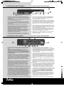
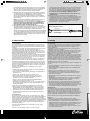
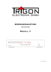
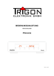
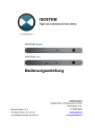
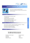
BEDIENUNGSANLEITUNG
Collins Professional Power Amplifiers
MP 200 • MP 600 • MP 1000 • MP 1200
Inhalt:
1. Bedienelemente auf der Frontplatte
2. Bedienelemente auf der Rückseite
3. Inbetriebnahme
4. Sicherheitshinweise
5. Technische Daten
Features:
• flexibles Anschlusskonzept mit symmetrischen XLR-Eingängen und parallelen Klinkenbuchsen
• Anschluss der Lautsprecherboxen via Speakonkabel
• zusätzliche Lautsprecher-Schraubklemmen („Banana-Jacks“) ermöglichen problemlose Rack-Installation
• zwei Betriebsarten: Neben dem herkömmlichen Stereobetrieb lassen sich beide Endstufenkanäle brücken
(„Bridged“-Betrieb), so dass die Gesamtleistung an einer Klemme addiert zur Verfügung steht.
• pro Kanal fünfteilige Signal/Clip-Leuchtdiodenanzeige
• pro Kanal Level-Regler zur Pegelanpassung
• Ground Lift-Schalter zur Vermeidung von Brummschleifen
• Lüfterkühlung sorgt für optimale Temperaturbedingungen auch bei hoher Belastung
OWNERS MANUAL
Collins Professional Power Amplifiers
MP 200 • MP 600 • MP 1000 • MP 1200
Content:
1. Control elements on the front panel
2. Control elements on the back panel
3. Start-Up
4. Safety instructions
5. Specification
Features:
• Flexible connections with symmetrical XLR inputs and parallel ¼“ jack inputs
• Connection of loudspeakers via speaker inputs
• Additional loudspeaker terminals („banana jacks“) allow easy rack installation
• Two operating modes: besides the common stereo mode both amplifier channels can
be bridged to delivery the total accumulated power into one single speaker output.
• Five signal/clip-LED’s per channel
• Level control per channel
• Ground Lift switch to avoid ground loops
• Fan cooling system for optimum temperature conditions even at highest Levels
Bedienungsanleitung.pmd
1
Schwarz
18.09.2002, 14:26
1. Bedienelemente auf der Frontplatte
1. Control elements on the front panel
4
6
1
5
2
3
1. Netzschalter und „Power“-LED: Um das Gerät einzuschalten, stecken Sie das
Netzkabel in eine Schuko-Steckdose und bringen Sie den Netzschalter in Position
»1«. Daraufhin leuchtet die „Power“-LED und zeigt die Betriebsbereitschaft Ihrer
Collins-Endstufe an.
2. „Bridge“-LED: Diese LED signalisiert, dass die Endstufe mit dem „Stereo/Bridge“Schalter (11) in den Brückenbetrieb geschaltet ist.
3. „Protect“-LED: Die „Protect“-Anzeige leuchtet auf, sobald die interne Schutzschaltung infolge Überlastung durch Übertemperatur anspricht. Zum Schutz der
angeschlossenen Lautsprecher ist die Schutzschaltung auch während des Ein- und
Ausschaltens aktiv.
4. „Left Level“-Regler: Mit diesem Regler können Sie den an der XLR- und
Klinkenbuchse des linken Kanals anliegenden Eingangspegel dämpfen und so die
Wiedergabelautstärke bestimmen. Steht der Regler am rechten Anschlag
(„vollständig offen“), verarbeitet die Endstufe exakt den anliegenden und an
Ihrem Mischpult angezeigten Ausgangspegel.
5. „Right Level“-Regler: Mit diesem Regler können Sie den an der XLR- und
Klinkenbuchse des rechten Kanals anliegenden Eingangspegel dämpfen und so die
Wiedergabelautstärke bestimmen. Steht der Regler am rechten Anschlag
(„vollständig offen“), verarbeitet die Endstufe exakt den anliegenden und an
Ihrem Mischpult angezeigten Ausgangspegel.
6. LED-Pegelanzeigen: Diese LED-Ketten informieren Sie über die Aussteuerungszustände beider Kanäle und auch über die Auslastung Ihrer Collins-Endstufe.
1. Power On/Off switch and „Power“-LED: to switch on the amplifier plug in the
power cord into an appropriate power outlet (230V, 50Hz) and bring the power
switch into position »1«. The Power-LED is lit and shows that your Collins
Professional Power Amplifier is ready to work.
2. „Bridge“-LED: this LED indicates that the amplifier is set to run in bridge mode,
that is activated with the „Stereo/Bridge“-switch (11) on the back of the amplifier.
3. „Protect“-LED: the „Protect“-LED lits as soon as the internal protection circuitry
has been triggered due an overload or overheating. To protect the connected
loudspeakers the circuitry is also activated while the amplifier is switched on or
off.
4. „Left Level“-potentiometer: this control attenuates the input signal (connected to
the XLR- or the jack input) of the left channel and allows you therefore to control
the volume. Turned fully clockwise the amplifier gets exactly the level indicated
from the connected signal source (e.g. a mixer).
5. „Right Level“-potentiometer: this control attenuates the input signal (connected
to the XLR- or the jack input) of the right channel and allows you therefore to
control the volume. Turned fully clockwise the amplifier gets exactly the level
indicated from the connected signal source (e.g. a mixer).
6. LED level indicators : these LED meters indicate the current levels of the left and
right input channels as well as the remaining headroom of your Collins
Professional Power Amplifier.
2. Bedienelemente auf der Rückseite
2. Control elements on the back panel
9
12
7
7
8
10
7. Lüfteröffnungen: Hier entweicht die zur Kühlung der Endstufe erforderliche Luft.
Stellen Sie sicher, dass diese Öffnungen während des Betriebs nicht verdeckt
werden.
8. Netzsicherung: Ersetzen Sie im Bedarfsfall die Sicherung nur durch einen
identischen Typ mit identischer Belastbarkeit. Nachdem Sie das Gerät vom
Stromnetz getrennt haben, können Sie den Sicherungseinsatz mit Hilfe eines
Schraubendrehers aus der Fassung entnehmen. Vorsicht: Höhere Absicherung
oder gar das Überbrücken kann im Falle eines Defekts zu schweren
Brandschäden führen!
9. Speaker-Buchsen: Hier schließen Sie Ihre Lautsprecherboxen an. Sie benötigen
dazu zweiadrige Lautsprecherkabel mit Speakon®-Steckern, die durchgehend auf
den Kontakten »1+« und »1-« belegt sind. Vieradrige Lautsprecherkabel mit NL-4Speakon® funktionieren ebenso. Beachten Sie stets die Mindestimpedanzen und
unterschreiten Sie sie (z.B. durch Parallelschaltung weiterer Boxen) nicht.
Collins-Endstufen arbeiten an pro Kanal vier Ohm Lautsprecherlast optimal.
Unterschreitung kann zu Überlastung und zum Ansprechen der Schutzschaltung
führen.
10. Schraubklemmen: Die Schraubklemmen sind den Speaker-Lautsprecherbuchsen
parallel geschaltet. Wenn Sie die Collins-Endstufe in ein Rack mit einem extra
Steckpanel oder einen Installationsschrank einbauen, können Sie hier die
Lautsprecherleitungen direkt anklemmen und die Speakonstecker einsparen.
Halten Sie dabei aber unbedingt die Polarität ein, indem Sie die Pluspole der
Boxen stets an die roten, die Minuspole dagegen immer an die schwarzen
Klemmen anschließen.
11. „Stereo/Bridge“-Schalter: Dieser Schalter stellt den Betriebsmodus der Endstufe ein.
Die Stellung „Stereo“ repräsentiert dabei den Normalfall, denn damit können Sie ein
Stereosignal oder auch zwei voneinander unabhängige Monosignale verstärken und
über zwei Lautsprecherboxen wiedergeben. In „Bridge“-Position hingegen werden
beide Endstufenkanäle quasi „huckepack“ zusammengekoppelt, so dass die
Ausgangsleistungen beider Kanäle addiert zur Verfügung stehen. Dieser Zustand
wird durch die „Bridge“-LED (2) auf der Frontplatte angezeigt. Allerdings können Sie
jetzt nur noch ein am Eingang des linken Kanals (CH L) anliegendes Monosignal
verstärken. Dieses führen Sie der Lautsprecherbox zu, indem Sie die beiden Leiter des
Boxenkabels an die beiden roten Schraubklemmen anschließen. Beachten Sie auch
hier die am Gerät aufgedruckte Polarität und die Impedanz der Box. Im Vergleich zu
vorher muss diese im Brückenbetrieb statt vier Ohm nun acht Ohm betragen.
12. XLR-Eingänge: Über die XLR-Eingänge können Sie die beiden Eingangssignale in
dreipoliger symmetrischer Form in Ihre Collins-Endstufe einspeisen. Die Belegung der
Bedienungsanleitung.pmd
2
Schwarz
11
14
13
7. Ventilation grills: the ventilation grills allow the amplifier to exhaust its heat.
Make sure that the grills are not covered during operation.
8. Fuse: In case of a failure of the fuse replace it only with a fuse of identical type
and identical specification. After disconnecting the amplifier from the power
outlet you can remove the fuse holder using a screw driver. Attention: the
application of higher rated fuses or bridging can cause severe damage (fire!) in
case of an amplifier failure!
9. Speaker connectors: plug in your loudspeaker here. You need a speaker cable with
two wires and a Speakon® connector. The active contacts are »1+« and »1-«.
Please watch the minimum impedance and do not connect speaker loads below
the rated values (e.g. caused by multiple loudspeakers connected in parallel).
Collins Professional Power Amplifiers work best at four ohms load impedance per
channel. A load below this rating can cause overload and triggers the protection
circuitry.
10. Screw Terminals: the screw terminals are in parallel with the speaker connectors
and allow you to save the Speakon® connectors when you install the Collins
Professional Power Amplifier with a separate patch panel or in an installation rack.
Please pay attention to correct polarity to make sure your PA system runs properly.
Switched polarities can cause severe influence on the frequency response of your
PA system.
11. „Stereo/Bridge“-switch: controls the operating mode of the amplifier. The position
„Stereo“ is meant for the common two channel mode that allows you to amplify a
stereo signal or two independent mono signals reproducing the signals via two
loudspeaker cabinets. In „Bridge“ position both amplifier channels will be
coupled, so that the total power is added into one single output. This operating
mode is indicated by the lit „Bridge“-LED (2) on the front panel. This mode
converts the device into a single channel amplifier, that only amplifies the signal of
the left input channel. The loudspeaker cabinet has to be connected by using the
two red screw terminals on the amplifier back panel. Please pay attention to
correct polarity and impedance. Important note: the minimum load
impedance in bridge mode is eight ohms instead of four ohms in
stereo mode!
12. XLR inputs: the XLR inputs allow the connection of symmetrical three pole input
signals to your Collins Professional Power Amplifier. The pin out of the XLR
connectors follows the international AES 14 standard. The „hot“ signal appears on
pin 2, the inverted „cold“ signal on pin 3. Pin 1 of the XLR input contacts the
signal ground which is connected to the shield of the cable.
13. Ground lift switch: the ground lift switch disconnects the signal ground from the
18.09.2002, 13:30
XLR-Buchsen folgt der internationalen Norm AES 14, nach der das nicht invertierte
bzw. „heiße“ Signal auf Pin 2, das phasengedrehte bzw. „kalte“ Pendant hingegen
auf Pin 3 anliegt. Pin 1 der XLR-Eingangsbuchse hat jeweils Kontakt mit der
Signalmasse, auf der Zuleitung ist er mit dem Kabelschirm verbunden.
13. Ground Lift-Schalter: Der Ground-Lift Schalter trennt die Signalmasse der Endstufe
vom Nullpotenzial des geerdeten Metallgehäuses ab. Dies ist vorteilhaft, wenn Sie
Ihre Collins-Endstufe mit einem Mischpult und/oder einer Frequenzweiche
ansteuern, die ebenfalls geerdet sind. Masseschleifen, die unter Umständen laut
störende Brummgeräusche in die Signalwege einkoppeln können, werden auf diese
Weise unterbrochen.
Hinweis: Verwenden Sie zur Bekämpfung von Brummeinstreuungen infolge von
Mehrfacherdungen immer nur den Ground Lift-Schalter oder fügen Sie in
hartnäckigen Fällen Audio-Trenntrafos in die Zuleitungen ein. Unterbrechen Sie
niemals den Schutzleiter der Netzzuleitung (z.B. durch Abkleben des
Netzsteckers) Ihrer Collins-Endstufe, denn sonst handeln Sie sich ein
unter Umständen tödliches Stromschlag-Risiko ein!
14. Klinkeneingänge: Möchten oder können Sie Ihre Collins-Endstufe mit einadrigabgeschirmten Klinkenkabeln nur unsymmetrisch ansteuern, so verwenden Sie dafür
die parallel vorhanden 6,3 mm-Klinkenbuchsen. Beachten Sie, dass diese dreipolig
ausgeführt und mit den drei Kontakten der jeweiligen XLR-Buchse parallel
verbunden sind. Mit einem dreipoligen Stereo-Klinkenkabel könnten Sie die Endstufe
also auch über die Klinkenbuchsen symmetrisch ansteuern. Wenn Sie ein herkömmliches, zweipoliges Kabel benutzen, wird automatisch auf unsymmetrisch umgestellt,
weil der längere Masseschaft des Mono-Klinkensteckers den „kalten“ Pin 3 mit der
Signalmasse auf Pin 1 kurzschließt.
electrical potential of the earthed metal enclosure. You can use this feature when
your Collins Professional Powwer Amplifier is connected to a mixer or any other
device that is also earthed. Ground loops, that may cause hum and noise in your
audio system, are interrupted this way. Important Note: Never disconnect
the earth connection of the amplifier to fight hum and noise!
Unearthed devices are extremly hazardous and may result in severe
electrical shocks!
14. Jack inputs: to feed your Collins Professional Power Amplifier with non
symmetrical jack cables you can use these ¼” inputs. Remember that these jacks
are implemented as a three pole contact that is connected in parallel to the XLR
inputs. Using a three pole stereo jack cable allows you to feed the amplifier
symmetrically as well. A common two pole cable with mono jacks automatically
switches the input to be non symmetrical since the shaft of the mono jack
shortcuts the pins 3 (“cold”) and pin 1 (“shield”).
3. Inbetriebnahme
3. Start-Up
3.1 Stereo-Betrieb
Im Stereo-Betrieb arbeitet Ihre Collins-Endstufe prinzipiell wie der Verstärker einer
Stereoanlage. Es stehen Ihnen zwei Verstärkerkanäle zur Verfügung, die Sie unabhängig voneinander nutzen können. Der Stereo-Betrieb eignet sich für folgende Anwendungen:
· Verstärkung eines Stereosignals, z.B. die fertig gemischte L/R-Summe Ihrer PA, oder das
Ausgangssignal eines DJ-Mixers oder einzelnen Zuspielers (CD-Player o.ä.).
· Verstärkung zweier Monitorwege: Um sich auf der Bühne selbst besser hören zu
können, benötigen Musiker Monitorboxen. Mit Hilfe der Aux-Wege lassen sich am
Mischpult dafür individuelle Mono-Mischungen erstellen, die Sie mit Ihrer CollinsEndstufe verstärken und den Monitorboxen zuführen können.
· Verstärkung eines Monitor- und eines PA-Signals: Gelegentlich kann die Ausgangsleistung eines einzelnen Endstufenkanals schon ausreichen, die Örtlichkeit ausreichend laut zu beschallen. In diesem Fall können Sie den zweiten, frei gebliebenen
Kanal zur Verstärkung eines Monitorweges nutzen.
· Verstärkung zweier verschiedener Frequenzwege, z.B. bei einer aktiv getrennten 2Wege PA. In diesem Fall trennt eine zwischen Pult und Endstufe geschaltete Frequenzweiche das Audiosignal in einen Bass- und einen Hochtonweg auf, die dann
von den beiden Endstufenkanälen getrennt verstärkt und über ein mehradriges Kabel getrennt an Hochtöner und Basslautsprecher der Box geliefert werden. Um eine
stereofone PA im Zweiweg-Aktivbetrieb zu realisieren, benötigen Sie folglich zwei
identische Collins-Endstufen.
3.1 Stereo mode
In stereo mode your Collins Professional Power Amplifier works pretty much like a
conventional amplifier of your home stereo system. Use can use the two amplifier
channels independently from each other. The stereo mode is suitable for the
following applications:
· Amplification of a stereo signal, e.g. the mixed L-R sum of your PA system, the
output signal of a DJ mixer or a CD-player.
· Amplification of two monitor signals: you can use floor monitor speakers on stage
to hear yourself better. By means of the auxiliary sends of a mixer you can create
individual mixes that can be amplified with your Collins Professional Power
Amplifier to power the appropriate floor monitor speakers.
· Amplification of two different signal paths of your PA system: a crossover between
mixer and amplifier divides the signal into two different spectral signals (e.g. high
and low for a 2-way PA). In this case one channel of the amplifier only amplifies the
hi frequency spectrum and the other channel the low frequency spectrum. So the
horn/driver combination is powered by one channel and the woofer is powered by
the other channel. As a result you would need two identical Collins Professional Power Amplifiers to set up a stereo 2-way active PA.
Gehen Sie bei der Inbetriebnahme Ihrer Collins-Endstufe im Stereo-Betrieb
folgendermaßen vor:
a. Schließen Sie die Boxen an die Speakon-Ausgänge (9) oder die Schraubklemmen
(10) an (hier bitte die Polarität beachten).
b. Legen Sie die zu verstärkenden Signale mit Hilfe von XLR- oder Klinkenkabeln auf
die Eingänge (12, 14).
c. Bringen Sie den „Stereo/Bridge“-Schalter (11) in Position „Stereo“.
d. Bevor Sie den Netzstecker einstecken, vergewissern Sie sich, dass sich der
Netzschalter (1) in Position »0« befindet und die beiden Level-Regler (4, 5)
zugedreht sind, sich also am linken Anschlag befinden.
e. Schalten Sie zuerst Ihr Mischpult und alle anderen beteiligten Audiogeräte
(Effektprozessoren, Kompressoren, CD-Player ect.) ein.
f. Jetzt betätigen Sie den Netzschalter. „Power“ (1)- und „Protect“-LED (3) leuchten
auf. Nach einigen Sekunden verlischt die „Protect“-LED wieder und Ihre CollinsEndstufe ist betriebsbereit.
g. Öffnen Sie nun beide Level-Regler (4, 5) langsam bis zum rechten Anschlag.
h. Den Betriebspegel und damit die Wiedergabelautstärke regeln Sie nun an Ihrem
Mischpult. Beachten Sie jedoch die LED-Anzeigen (6) an Ihrer Collins-Endstufe.
Beginnt eine der obersten roten Clip-LEDs gelegentlich aufzuleuchten, dürfen Sie
den Eingangspegel des betroffenen Kanals nicht weiter erhöhen. Andernfalls
entstehen Übersteuerungsverzerrungen, die unter Umständen Ihre Lautsprecher
beschädigen können.
3.2 Bridge-Betrieb
Im Gegensatz zum Stereo-Betrieb kann der so genannte Brücken- bzw. „Bridge“Betrieb nur ein Monosignal verarbeiten, das aber auf die doppelte Ausgangsleistung
verstärkt wird. Sinnvoll ist dies beispielsweise, wenn Sie eine Bassbox betreiben
wollen und dafür mehr Leistung benötigen, als ein einzelner Kanal Ihrer Collins-Endstufe bereitstellen kann. Da die minimale Ausgangsimpedanz im Brückenbetrieb acht
Ohm beträgt und die meisten Bassboxen ebenfalls diese Impedanz aufweisen, ist
automatisch die optimale elektrische Anpassung und Leistungsausnutzung Ihrer
Collins-Endstufe garantiert.
Gehen Sie bei der Inbetriebnahme Ihrer Collins-Endstufe im „Bridge“-Betrieb
folgendermaßen vor:
a. Bringen Sie den „Stereo/Bridge“-Schalter (11) in Position „Bridge“.
Bedienungsanleitung.pmd
3
Schwarz
Belegung symmetrische Steckverbinder
Pin Out symmetrical connectors
+ Phase („hot“)
3
- Phase („cold“)
1
2
Abschirmung (shield)
Take the following steps to start-up your Collins Professional Power Amplifier in stereo mode:
a. Connect the loudspeakers to the speaker connectors (9) or the screw terminals (10).
Please mind the polarity.
b. Feed the signal you want to amplify to the inputs (12, 14) of the amplifier using
XLR- or jack cables.
c. Make sure to set the „Stereo/Bridge“ switch (11) to position „Stereo“.
d. Before plugging the power connector into the power socket make sure that the
power on/off switch (1) is in position »0« and that the level controls (4, 5) are
turned fully counter clockwise.
e. Primarily switch on all other connected gear (i.e. mixer, FX-processors, compressors,
CD-player a.s.o.).
f. Now bring the power on/off switch to position »1«. „Power“ (1) - and „Protect“LED’s (3) lit. Wait a few seconds so that the „Protect“-LED goes out and your
Collins Professional Power Amplifier is ready for operation.
g. Turn both level controls (4, 5) slowly and fully clockwise now. Now you control the
operating level and the system volume with your mixer. Please watch the LED
meters (6) of your amplifier. When the red clip LED’s at the top start to lit you must
not increase the input level of the appropriate input channel. Otherwise you cause
overload that result in distortion that may damage your speaker system.
3.2 Bridge mode
The bridge mode allows you to amplify a single signal with twice the power of a
stereo channel. This may make sense if you want to operate a subwoofer which
requires more power than a single channel of your Collins Professional Power
Amplifier is able to deliver. Since the minimum load impedance in bridge mode is 8
ohms and a majority of the available subwoofers have this impedance rating, proper
electrical matching and optimum performance are automatically accomplished.
Take the following steps to start-up your Collins Professional Power Amplifier in
bridge mode:
a. Make sure to set the „Stereo/Bridge“ switch (11) to position „Bridge“.
b. Connect the loudspeakers to the screw terminals (10). The output signal in bridge
mode is available at the two red terminals. Connect the positive pole of the
loudspeaker lead with the red terminal labeled »+«of the left channel („CH L“). The
negative pole has to be connected to the red terminal of the right channel („CH
R“). In bridge mode the two black terminals are without function.
c. Connect the signal you want to amplify with the input of the left channel („CH L“,
12, 14) using a XLR- or jack cable.
18.09.2002, 13:21
b. Schließen Sie die Box an die Schraubklemmen (10) an. Beachten Sie, dass im
„Bridge“-Modus das Ausgangssignal zwischen den beiden roten Klemmen anliegt.
Verbinden Sie deshalb den Pluspol der Lautsprecherleitung mit der mit »+«
gekennzeichneten roten Klemme des linken Kanals („CH L“), der Minuspol kommt
an die links davon befindliche, rote Klemme des rechten Kanals („CH R“). Die
beiden schwarzen Klemmen haben im Brückenbetrieb keine Funktion.
c. Legen Sie das zu verstärkende Signale mit Hilfe eines XLR- oder Klinkenkabels auf
die Eingangsbuchsen des linken Kanals („CH L“, 12, 14).
d. Bevor Sie den Netzstecker einstecken, vergewissern Sie sich, dass sich der
Netzschalter (1) in Position »0« befindet und die beiden Level-Regler (4, 5)
zugedreht sind, sich also am linken Anschlag befinden.
e. Schalten Sie zuerst Ihr Mischpult und alle anderen beteiligten Audiogeräte
(Frequenzweiche, Effektprozessoren, Kompressoren, CD-Player ect.) ein.
f. Jetzt betätigen Sie den Netzschalter. „Power“ (1)-, „Bridge“ (2)- und „Protect“-LED
(3) leuchten auf. Nach einigen Sekunden verlischt die „Protect“-LED wieder und
Ihre Collins-Endstufe ist betriebsbereit.
g. Öffnen Sie nun den Level-Regler des linken Kanals (4) langsam bis zum rechten
Anschlag. Der Level-Regler des rechten Kanals (5) ist im „Bridge“-Betrieb außer
Funktion.
d. Before plugging the power connector into the power socket make sure that the
power on/off switch (1) is in position »0« and that the level controls (4, 5) are
turned fully counter clockwise.
e. Primarily switch on all other connected gear (i.e. mixer, FX-processors, compressors,
CD-player a.s.o.).
f. Now bring the power on/off switch to position »1«. „Power“ (1) - and „Protect“LED’s (3) lit. Wait a few seconds so that the „Protect“-LED goes out and your
Collins Professional Power Amplifier is ready for operation.
g. Turn the level control of the left channel (4, 5) slowly and fully clockwise now.
Now you control the operating level and the system volume with your mixer (and/or
output of the crossover). Please watch the LED meters (6) of your amplifier. When
the red clip LED’s at the top start to lit you must not increase the input level of the
appropriate input channel. Otherwise you cause overload that result in distortion
that may damage your speaker system.
4. Sicherheitshinweise
4. Safety instructions
a. Collins-Endstufen sind für die Rackmontage ausgelegt. Mit Hilfe der Montagewinkel an den Seiten, den so genannten „Rackohren“, und vier 6 mm Gewindeschrauben können Sie Ihr Gerät in ein genormtes 19„-Rack oder einen ebensolchen Installationsschrank einbauen. Besonders bei den schwereren Geräten „MP
1000“ und „MP 1200“ sollten Sie auch die an den hinteren Gehäuseflanken
zusätzlich vorhanden Montagebohrungen nutzen, denn dies verleiht ihrem Gerät
in einem transportablen Rack zusätzlichen Halt und damit Sicherheit.
b. Achten Sie bei der Rackmontage stets auf frei bleibende Lüftungsöffnungen, damit
die Kühlung gewährleistet ist. Befinden sich mehrere Endstufen in einem Rack, ist
zur Vermeidung von Wärmestaus ein zusätzlicher Umlüfter empfehlenswert.
c. Stellen Sie ihre Collins-Endstufe nicht an feuchten oder extrem warmen Orten wie
z.B. in der Nähe von Heizgeräten oder in der prallen Sonne auf. Vermeiden Sie
ebenfalls staubige Umgebungen, denn sonst entstehen im Inneren des Gerätes
Staubablagerungen, die irgendwann die Funktion beeinträchtigen können.
d. Behandelt Sie das Gerät und auch alle beteiligten Kabel umsichtig.
e. Verwenden Sie zum Reinigen des Gehäuse ein trockenes Tuch, keine aggressiven
Reinigungs- oder Lösungsmittel.
f. Stellen Sie sicher, dass der Schutzleiter des Netzkabels immer Kontakt zur Erdung
bekommt, um die Schutzerdung des Gerätes zu gewährleisten.
g. Ersetzen Sie die Netzsicherung nur durch ein Exemplar mit identischer Belastbarkeit.
h. Wenn Sie zum Anschluss der Lautsprecher die Schraubklemmen verwenden,
achten Sie darauf, dass die abisolierten Kabelenden nicht zu weit überstehen.
Andernfalls besteht Kurzschlussgefahr mit dem Gehäuse.
i. Unterschreiten Sie nicht die minimal zulässige Lastimpedanz. Diese beträgt im
Stereo-Modus pro Kanal vier Ohm und im Brückenbetrieb acht Ohm.
j. Sollten Reparaturen notwendig werden, so überlassen Sie diese bitte dem
qualifizierten Kundendienst in Ihrer Musik Produktiv-Filliale. Beim Öffnen oder
Modifizieren Ihrer Collins-Endstufe erlischt automatisch der Garantieanspruch.
a. Collins Professional Power Amplifiers are designed to be mounted in racks. By
using the installations frames on the sides and four screws with 6mm threads you
are able to mount the device into standardized 19”-racks. The heavier devices
MP1000 and MP1200 should be additionally secured by using the threads in the
back sides of the enclosure. This provides extra safety when your Collins
Professional Power Amplifier is mounted in a mobile rack.
b. Make sure that the ventilation grills are not covered when the amplifier is installed
in a rack, so that sufficient cooling is provided. We recommend to use an extra
external fan when multiple amplifiers are mounted in one rack.
c. Do not expose your Collins Professional Power Amplifier to extremly hot or humid
environments (e.g. close to the heating or in the sun). Avoid dusty environments
because the occuring dust deposit inside the amplifier leads to mal function on the
long term run. Do not use your device close to water sources.
d. Make sure that the device and all connected cables (especially the line cord) are in
good condition before using them.
e. To clean the device only use a dry cleaning cloth. Avoid using aggressive
detergents.
f. Make sure the device is always earthed. Make sure the ground wire is always
connected to earth.
g. Replace the fuse only with a fuse of identical rating and specification.
h. When using the screw terminals for connecting the loudspeakers make sure that
the bared ends of the cable do not shortcut with the metal enclosure of the device.
i. Mind the minimum load impedance. It is 4 ohms in stereo mode and 8 ohms in
bridge mode.
j. Service has to be done by qualified technicians only. Opening and/or modifying the
amplifier lets all warranty claims become void. When you suspect your amplifier
needs service, please contact the dealer where you purchased the device first.
5. Technische Daten
5. Specification
MP200
MP600
MP1000
Ausgangsleistung:
zwei Kanäle @ 8 Ohm
2x 100W
2x 200W
2x 300W
zwei Kanäle @ 4 Ohm
2x 175W
2x 350W
2x 525W
Brücke @ 8 Ohm
1x 200W
1x 400W
1x 600W
Max. Leistung @ 1kHz:
zwei Kanäle @ 8 Ohm
2x 135W
2x 275W
2x 350W
zwei Kanäle @ 4 Ohm
2x 200W
2x 475W
2x 600W
Brücke @ 8 Ohm
n.r.
n.r.
n.r.
Slew rate
>30V/ms
>30V/ms
>30V/ms
THD 20Hz – 20kHz
< 0.5%
< 0.5%
< 0.5%
Übertragungsbereich
+/ 0.5dB
+/ 0.5dB
+/ 0.5dB
20Hz – 20kHz
Signal/Rauschabstand
> 98dB
> 98dB
> 98dB
Kanaltrennung @1kHz
> 82dB
> 82dB
> 82dB
Empfindlichkeit sym. / 0dB / +4dBu 0dB / +4dBu 0dB / +4dBu
unsym.
Eingangsimpedanz
>10kOhm
>10kOhm
>10kOhm
Eingänge
XLR & 6.3mm XLR & 6.3mm XLR & 6.3mm
Stereoklinke Stereoklinke Stereoklinke
Ausgänge
2x Speaker & 2x Speaker & 2x Speaker &
SchraubanSchraubanSchraubanschlüsse
schlüsse
schlüsse
Schutzschaltungen
Überhitzung
Überhitzung Überhitzung,
Softstart
Netzversorgung
230V – 50Hz 230V – 50Hz 230V – 50Hz
Gewicht
13kg
17kg
20kg
Abmessungen
480x370x88
480x370x88
480x430x88
Irrtümer und Änderungen vorbehalten
Bedienungsanleitung.pmd
2x 400W
2x 675W
1x 800W
2x 430W
2x 725W
n.r.
>30V/ms
< 0.5%
+/ 0.5dB
> 98dB
> 82dB
0dB / +4dBu
>10kOhm
XLR & 6.3mm
Stereoklinke
2x Speaker &
Schraubanschlüsse
Überhitzung,
Softstart
230V – 50Hz
21.5kg
480x430x88
M P 200
Rated output power:
dual c hannel @ 8 ohm s
2x 100W
dual c hannel @ 4 ohm s
2x 175W
bridge m ode @ 8 ohm s
1x 200W
M ax . power @ 1k Hz :
dual c hannel @ 8 ohm s
2x 135W
dual c hannel @ 4 ohm s
2x 200W
bridge m ode @ 8 ohm s
n.r.
S lew rate
> 30V /m s
THD 20Hz – 20k Hz
< 0.5%
Frequenc y res pons e
+ / 0.5dB
20Hz – 20k Hz
S ignal to Nois e
> 98dB
Channel Is olation
> 82dB
@ 1k Hz
S ens ivity s y m . / non
0dB / + 4dB u
sym.
Input im pedanc e
> 10k Ohm
Input c onnec tions
XLR, ¼ ”
s tereo jac k
Output c onnec tions
2x S peak er,
s c rew
term inals
P rotec tions
Tem perature
P ower requirem ents
W eight
Dim ens ions
M P 600
M P 1000
M P 1200
2x 200W
2x 350W
1x 400W
2x 300W
2x 525W
1x 600W
2x 400W
2x 675W
1x 800W
2x 275W
2x 475W
n.r.
> 30V /m s
< 0.5%
+ / 0.5dB
2x 350W
2x 600W
n.r.
> 30V /m s
< 0.5%
+ / 0.5dB
2x 430W
2x 725W
n.r.
> 30V /m s
< 0.5%
+ / 0.5dB
> 98dB
> 82dB
> 98dB
> 82dB
> 98dB
> 82dB
0dB / + 4dB u 0dB / + 4dB u 0dB / + 4dB u
> 10k Ohm
> 10k Ohm
XLR, ¼ ”
XLR, ¼ ”
s tereo jac k
s tereo jac k
2x S peak er, 2x S peak er,
s c rew
s c rew
term inals
term inals
Tem perature Tem perature
, S ofts tart
230V – 50Hz 230V – 50Hz 230V – 50Hz
13k g
17k g
20k g
480x 370x 88 480x 370x 88 480x 430x 88
All rights reserved
4
Schwarz
MP1200
18.09.2002, 13:21
> 10k Ohm
XLR, ¼ ”
s tereo jac k
2x S peak er,
s c rew
term inals
Tem perature
, S ofts tart
230V – 50Hz
21.5k g
480x 430x 88