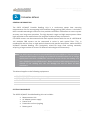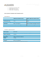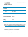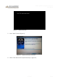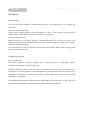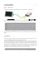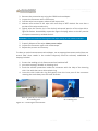
1
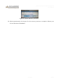
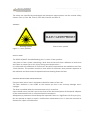
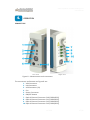
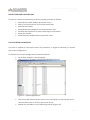
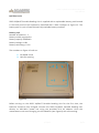
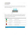
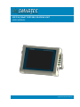
SOFO VII/MuST PORTABLE READING UNIT USER MANUAL Engineered by FiberSensing SOFO VII/MuST Portable Reading Unit User Manual SOFO VII/MuST Portable Reading Unit User Manual Measurement Unit Version: v1.0 User Manual version: v0.4 Any questions or comments regarding this guide please report to: [email protected] Jul.2013 3/31 SOFO VII/MuST Portable Reading Unit User Manual 1. INDEX Technical details 7 GENERAL INFORMATION SYSTEM COMPONENTS SOFO VII/MUST READING UNIT TECHNICAL DATA Performance Technical Characteristics 7 7 8 8 8 SOFO MUX 1X5 TECHNICAL DATA 9 Performance Technical Characteristics 9 9 HARD DISK IMAGE RECOVERY 9 System Recovery 9 Regulatory and certification considerations CE CONFORMITY ENVIRONMENT CONSIDERATIONS 13 13 14 Disposal of your old appliance 14 LASER SAFETY 14 Symbols Class 1 laser General precautions considerations 15 15 15 Operation 17 CONNECTORS PROTECTION AND CARRYING BAG TOUCH SCREEN CALIBRATION BATTERY PACK 17 18 18 20 Removing the Battery Pack Connecting the Battery Pack 21 22 STATUS INDICATORS SETTING UP 23 24 Power supply Connecting sensors 24 24 SWITCHING ON SWITCHING OFF CONTROLING THE UNIT 26 27 27 Interface Software 27 27 CLEANING PROCEDURE 28 Jul.2013 5/31 SOFO VII/MuST Portable Reading Unit User Manual Dry cleaning technique Wet cleaning technique 29 30 Jul.2013 6/31 SOFO VII/MuST Portable Reading Unit User Manual 2. TECHNICAL DETAILS GENERAL INFORMATION The SOFO VII/MuST Portable Reading Unit is a continuous swept laser scanning measurement unit for interrogating SOFO and fiber Bragg grating (FBG) sensors. It includes a NIST traceable wavelength reference that provides continuous calibration to ensure system accuracy over long term operation. The high dynamic range and high output power allows high resolution to be attained even for long fiber leads and lossy connections. Five SOFO sensors can be measured with each optical channel with the use of a SOFO MUX 1x5. Multiple FBG sensors can be connected in series in each optical fiber. This, in combination with the four or eight optical channels with parallel acquisition, make the SOFO VII/MuST Portable Reading Unit particularly suited for large scale sensing networks, acquiring a large number of sensors of different technologies simultaneously. Note: The SOFO sensors cannot be connected directly to the SOFO VII. The only way to measure a SOFO sensor is to plug it to a channel of the SOFO MUX 1x5 or using a hybrid patch cord with a E2000/APC connector on one side (to the reading unit) and a E2000/PC (to the SOFO sensor). Never connect a SOFO sensor directly to a channel of the reading unit, this can damage the core of fibers of both connectors. This Manual applies to the following equipments: PN S10.2021-PORT SOFO VII/MuST Portable Reading Unit • 4 OC PN S10.2021-MUX SOFO MUX 1x5 SYSTEM COMPONENTS The SOFO VII/MuST Portable Reading Unit set includes: Measurement Unit AC Adapter power supply Power cord Protection and carrying bag Battery pack Jul.2013 7/31 SOFO VII/MuST Portable Reading Unit User Manual Connector protection caps SOFO Reference sensor SOFO MUX 1x5 (optional) SOFO VII/MUST READING UNIT TECHNICAL DATA PERFORMANCE SOFO Sensors Measurement MuST /FBG Sensor Measurement Measurement Resolution 2 μm RMS 1 pm Linearity/Accuracy < 2‰ 2 pm Measurement Range Max. 50 mm 100 nm (1500 to 1600 nm) Calibration None, not required NIST traceable wavelength reference Measurement time < 2 s (inc SDB writing) per channel < 2 s (inc SDB writing) per channel Available channel count 4 channels total, software configurable between SOFO and MuST TECHNICAL CHARACTERISTICS Power supply 18-20 VDC External connections Ethernet connection, 4 optical ports, power supply Battery autonomy 3 hours* Data logger capacity Typical 5 year of data with measurements every 1h Dimensions 360 mm x 275 mm x 100 mm Weight ~7.5 Kg Operating temperature 10 ºC to +40 ºC Humidity 90% non-condensed * with one battery pack. Extra battery packs available upon request Jul.2013 8/31 SOFO VII/MuST Portable Reading Unit User Manual SOFO MUX 1X5 TECHNICAL DATA PERFORMANCE Channel Multiplexing 1x5 Operating Range Channel 1 1501 to 1519 nm Channel 2 1521 to 1539 nm Channel 3 1541 to 1559 nm Channel 4 1561 to 1579 nm Channel 5 1581 to 1599 nm Insertion loss <1.5 dB TECHNICAL CHARACTERISTICS Connectors to SOFO Sensors E2000/APC E2000/PC Dimensions 163mm x 103 mm x 53 mm Weight 0.43 Kg Material Aluminum Operating temperature -25 to 70 ºC < 90% at 40 ºC Connectors to Measurement Unit Humidity HARD DISK IMAGE RECOVERY The SOFO VII/MuST Portable Reading Unit has a functionality to recover all hard disk factory contents, restoring the default settings and original configurations of the Measurement Unit. Attention! System recovery will erase all the data stored in the hard disk. SYSTEM RECOVERY To apply the recovery process, follow the instructions as explained: 1. 2. 3. 4. Turn off the device Connect the keyboard and mouse to the device Turn on the device When the splash screen (Figure 1) appears press “F10” Jul.2013 9/31 SOFO VII/MuST Portable Reading Unit User Manual Figure 1 – Restore Screen. 5. Press “Next” button (Figure 2) Figure 2 – System Recovery Interface. 6. Select “Non Destructive System Recovery” (Figure 3) Jul.2013 10/31 SOFO VII/MuST Portable Reading Unit User Manual Figure 3 - System Recovery Interface. 7. Press “Next” (Figure 4) Figure 4 - System Recovery Interface. 8. Press “Yes” (Figure 5) Figure 5 - System Recovery Interface. 9. Press “Yes” (Figure 6) Jul.2013 11/31 SOFO VII/MuST Portable Reading Unit User Manual Figure 6 - System Recovery Interface. 10. Allow approximately 10 minutes for the recovery process to complete. Reboot your PC into Windows Embedded™. Jul.2013 12/31 SOFO VII/MuST Portable Reading Unit User Manual 3. REGULATORY AND CERTIFICATION CONSIDERATIONS CE CONFORMITY The SOFO VII/MuST Portable Reading Unit is a FiberSensing product that complies with legal European certification standards – CE Certification. The manufacture company FiberSensing, Sistemas Avançados de Monitorização, S.A. Rua Vasconcelos Costa, 277 4470-640 Maia Portugal Declares under sole responsibility that the product type as originally delivered Product name: Measurement Unit for optical Sensors Product trademark: FiberSensing Product model: SOFO VII/MuST Portable Reading Unit Product version: 1.0 Product options: all product options Is in compliance with the essential requirements, harmonized applicable standards, and carries the CE marking and other relevant provisions accordingly following directives: Directives 2006/95/EC relating Electrical Safety Directives 2004/108/EC relating Electromagnetic Compatibility Electrical Safety Standards: EN 61010-1: Safety requirements for electrical equipment for measurement, control, and laboratory use - Part 1: General requirements EN 60825-1: Laser Safety Standards – Part 1: equipment classification, requirements and user's guide Electromagnetic Compatibility Standards: EN 61326: Electrical equipment for measurement, control and laboratory use – EMC Standards: Emission: EN 55022 – class B; EN 61000-3-2; N 61000-3-3; Immunity: EN 61000-4-2 (level 3); EN 61000-4-3 (level 3); Jul.2013 13/31 SOFO VII/MuST Portable Reading Unit User Manual EN 61000-4-4 (level 3); EN 61000-4-5 (level 3); EN 61000-4-6 (level3); EN 61000-4-8; EN 61000-4-11. The original CE DofC (CE Declaration of Conformity) of SOFO VII/MuST Portable Reading Unit product is available through request directly to Smartec or Smartec reseller contact. ENVIRONMENT CONSIDERATIONS DISPOSAL OF YOUR OLD APPLIANCE When the attached symbol combination - crossed-out wheeled bin and solid bar symbol is attached to a product it means the product is covered by the European Directive 2002/96/EC and is applicable in the European Union and other countries with separate collection systems. All electrical and electronic products should be disposed of separately from the municipal waste stream or household via designated collection facilities appointed by the government or the local authorities. The correct disposal of your old appliance will help prevent potential negative consequences for the environment and human health. For more detailed information about disposal of your old appliance, please contact your city office, waste disposal service or distributor that purchased the product. FiberSensing is a manufacturer registered in the ANREEE - "Associação Nacional para o Registo de Equipamentos Eléctricos e Electrónicos" under number PT001434. FiberSensing celebrated a "Utente" type contract with Amb3E - "Associação Portuguesa de Gestão de Resíduos de Equipamentos Eléctricos e Electrónicos", which ensures the transfer of Electrical and Electronic appliance waste management, i.e. placing Electronic and Electrical appliances in the Portuguese market, from the manufacturer (FiberSensing) to Amb3E. LASER SAFETY The SOFO VII/MuST Portable Reading Unit product contains a laser in its core. A laser is a light source that can be dangerous to people exposed to it. Even low power lasers can be hazardous to a person's eyesight. The coherence and low divergence of laser light means that it can be focused by the eye into an extremely small spot on the retina, resulting in localized burning and permanent damage. Jul.2013 14/31 SOFO VII/MuST Portable Reading Unit User Manual The lasers are classified by wavelength and maximum output power into the several safety classes: Class 1, Class 1M, Class 2, Class 2M, Class 3R and Class 4. SYMBOLS Warning symbol Figure 7 – Laser Symbols. Class 1 Laser symbol CLASS 1 LASER The SOFO VII/MuST Portable Reading Unit is a class 1 laser product: «Any laser or laser system containing a laser that cannot emit laser radiation at levels that are known to cause eye or skin injury during normal operation. » It is safe under all conditions of normal use. No safety requirements are needed to use Class 1 laser devices. This product contains a laser within an enclosure that prevents exposure to the radiation and that cannot be opened without shutting down the laser. GENERAL PRECAUTIONS CONSIDERATIONS Everyone who uses a laser’s equipment should be aware of the risks. The laser radiation is not visible to the human eye but it can seriously damage user’s eyesight. The laser is enabled when the measurement unit is turned on. Users should never put their eyes at the level of the horizontal plane of the optical adapters of the measurement unit or uncovered optical connectors. Adequate eye protection should always be required if there is a significant risk for eye injury. Do not attempt to open or repair a malfunction measurement unit. It must be returned to Smartec for repair and calibration. Jul.2013 15/31 SOFO VII/MuST Portable Reading Unit User Manual 4. OPERATION CONNECTORS Left view Right view Figure 8 – Measurement unit connectors. The connectors and buttons on Figure 8 are: 1. VGA Connector 2. LAN Connector 3. USB Connector (2x) 4. Fan 5. Power Connector 6. ON/OFF button 7. Optical Channel Connector CH0 (E2000/APC)) 8. Optical Channel Connector CH1 (E2000/APC)) 9. Optical Channel Connector CH2 (E2000/APC)) 10. Optical Channel Connector CH3 (E2000/APC)) Jul.2013 17/31 SOFO VII/MuST Portable Reading Unit User Manual PROTECTION AND CARRYING BAG To place or remove the protection and carrying bag, proceed as follows: Remove the handle fixation protection cover; With a Torx screw driver 20 unscrew the handle; Remove the handle; Place/Remove the bag from the measurement Unit; Put back the handle on its place respecting its orientation; Screw the handle. Place back the handle fixation protection cover TOUCH SCREEN CALIBRATION If a cover is applied on the touch screen for protection, it might be necessary to repeat the screen configuration. To perform the screen configuration proceed as follows: Go to Start and press “My Computer”. Open the file C:\Program Files\UPDD\TBCALIB (Figure 9). Figure 9 – TBCALIB application. The screen will become white and a cross will appear on the top left corner. Use the screen pen to click on the center of this. Repeat the procedure on the following crosses (Figure 10). Jul.2013 18/31 SOFO VII/MuST Portable Reading Unit User Manual Figure 10 – Calibration procedure. Press the “Confirm” button (Figure 11). Figure 11 – End of calibration procedure. Jul.2013 19/31 SOFO VII/MuST Portable Reading Unit User Manual BATTERY PACK SOFO VII/MuST Portable Reading Unit is supplied with a replaceable battery pack located in the back panel of the equipment, identified with a blue rectangle on Figure 12. The battery pack is a pair of two commercially available battery modules. Battery pack Number of batteries: 2 Battery model: pcga-bp2nx Battery capacity: 4400mAh Battery voltage: 14.8V Battery technology: Li-ion The numbers on Figure 12 refer to: 1. Csk M4x8 screw 2. Hole for opening Figure 12 Before turning on the SOFO VII/MuST Portable Reading Unit for the first time, the batteries should be fully charged. Connect the SOFO VII/MuST Portable Reading Unit directly to 100~240 V power line using the provided 20 V AC adapter. Once the measurement unit starts charging, the left sided fan (see Figure 8) will start working. Jul.2013 20/31 SOFO VII/MuST Portable Reading Unit User Manual The replaceable battery pack has two independent batteries. To avoid lifetime reduction of the batteries this device manages charge-discharge cycles, as result of this process some charge cycles will not reach the maximum charge level of 100%. The estimated time to fully charge the battery pack is about 4 hours. Note: It is advisable to fully recharge and remove the battery pack before periods of inactivity longer than 4 weeks, see “Removing the Battery Pack” section on page 21. REMOVING THE BATTERY PACK Changing batteries is a simple process that must be performed following the procedure here described, since irreversible damage can be caused due to incorrect use. Attention: Take the necessary precautions to avoid Electro Static Discharge (ESD). To change the batteries proceed as follows: 1. Shut down the Measurement Unit and wait until the power LED is off. 2. Unplug the power supply cable if connected to the measurement unit. 3. Unscrew Csk M4x8 screws, number 1 on Figure 12. 4. Pull the battery cover rotating on the bottom edge and then remove it. To lift-up the pack, use a screwdriver as shown on Figure 13. Do not insert the screw driver more than few millimeters. Figure 13 Figure 14 5. Pull the edge of the battery vertically, number 1 on Figure 15. 6. Remove the battery by sliding it horizontally, number 2 on Figure 15. 7. Repeat the process for the second battery, see Figure 16. Jul.2013 21/31 SOFO VII/MuST Portable Reading Unit User Manual Figure 15 Figure 16 CONNECTING THE BATTERY PACK Attention: Make sure the Measurement Unit is switched off before placing the batteries. To connect a battery pack, proceed as follows: 1. Align the Battery Pack in the Back Panel slot, as in Figure 17. Take particular attention not to damage the pins of the connection, blue rectangle on Figure 17. Figure 17 1. Slide the battery horizontally, number 1 on Figure 15, until the battery is connected on the blue rectangle (blue rectangle on Figure 17). 2. Lower the edge of the Battery down, number 2 on Figure 15. 3. Repeat the process for the second battery and screw the cover. Jul.2013 22/31 SOFO VII/MuST Portable Reading Unit User Manual STATUS INDICATORS On the bottom of the screen panel the user can find three indicators. Number 1 on Figure 18 refers to the power status of the equipment, number 2 refers to the battery status and number 3 refers to disk writing. Figure 18 – Status indicator LEDs. Number 1 and number 3 on Figure 18 can only assume one color. When led 1 is green the measurement unit is powered on and when led 3 is yellow the hard disk is being written. The battery status (Led number 2 on Figure 18) assumes different colors depending on charge level, according to the following table. Battery Led Steady green Charge level > 60% Steady orange 60% > Charge level > 35% Steady red 35% > Charge level > 20% Blinking red Charge level < 20% Attention! Battery with less than 20% of maximum charge will compromise the correct startup of the measurement unit. Jul.2013 23/31 SOFO VII/MuST Portable Reading Unit User Manual SETTING UP POWER SUPPLY To start the SOFO VII/MuST Portable Reading Unit the measurement unit should be powered. OPERATING WITHOUT BATTERIES Connect the supplied power cable and adapter to 100 - 240 V power line and to the measurement unit Power Connector (number 5 on Figure 8). OPERATING WITH BATTERIES Before turning on the SOFO VII/MuST Portable Reading Unit for the first time, the batteries should be fully charged. Refer to section «Battery pack» on page 20 for further details on battery handling. The measurement unit can operate connected to the power supply while charging the batteries at the same time. CONNECTING SENSORS OPTICAL CONNECTORS The SOFO VII/MuST Portable Reading Unit is delivered with 4 E2000/APC optical connectors (numbers 7 to 10 on Figure 8). Attention should be paid to the cleaning of the optical connectors. A dirty connector can compromise the measurement and will degrade the measurement unit performance. It is advisable to frequently clean the connectors using appropriate tools (see Cleaning Procedure on page 28). The E2000/APC connectors and Mating are identified by the green color, in the Figure 19 are shown an E2000/APC connector and an E2000/APC Mating adapter: Jul.2013 24/31 SOFO VII/MuST Portable Reading Unit User Manual Figure 19 - E2000/APC connecter and E2000/APC mating adapter. The SOFO VII/MuST Portable Reading Unit can measure FBG sensors (identified by a green E2000/APC connector) and SOFO sensors (identified by a blue E2000/PC connector) plugged to the SOFO MUX 1x5, in the Figure 20 are shown a E2000/APC connector (FBG) and E2000/PC Connector (SOFO): Figure 20 - E2000/APC connecter (FBG) and E2000/PC connecter (SOFO). SOFO MUX 1X5 The SOFO MUX 1X5 is a device that allows to measure up to 5 SOFO sensors on a single channel of the reading unit. It is an external 1x5 splitter, a picture of the device is the following: Jul.2013 25/31 SOFO VII/MuST Portable Reading Unit User Manual Figure 21 – SOFO MUX 1x5. The connection schema of the SOFO MUX 1X5 to the SOFO VII is the following: Figure 22 – Connection scheme between the SOFO VII and the SOFO MUX 1x5. Note: The SOFO MUX 1X5 has six connectors: five E2000/PC for the SOFO sensors and one E2000/APC to which must be connected the patch cord attached to a channel of the SOFO VII. All the SOFO sensors connected to the MUX must mount an E2000/PC connector and the patch cord used to connect the MUX to the SOFO VII must have on both sides E2000/APC connectors. If this is not respected there is the possibility to irretrievably damage the core of the fiber and as consequence it will be impossible to measure the SOFO sensors. The characteristics of SOFO MUX are shown section SOFO MUX 1x5 Technical Data on page 9. SWITCHING ON Pressing the “ON/OFF” button (see on section Connectors Figure 8 on page 17) will start the engine. The SDB software will be automatically launched. Once the measurement unit is turned on both fans (see on section Connectors Figure 8 on page 17) will start working. The Power LED (number 1 on Figure 18) will start blinking at 2Hz. After approximately 30 seconds it will start blinking at 1Hz. This means that the measurement unit is already on and responsive, but the optoelectronic module is still warming up. After approximately one and a half minutes (90 s) it should stay on permanently. This means that the measurement unit is able to measure. Note: If the unit does not start correctly, the status led will blink faster. If this happens please contact Smartec technical support. Jul.2013 26/31 SOFO VII/MuST Portable Reading Unit User Manual SWITCHING OFF To switch off the measurement unit proceed in one of the following ways: 1. While running the iLog software: a. Press the “Exit” button. If for the active configuration the settings are set to “shut down on exit”, the measurement unit will shut down directly. If not, the software is active and steps described in 2 should be performed. Refer to the software user manual for further details. b. Press and release the ON/OFF button for ~250 milliseconds. A pop-up will appear to confirm the action. 2. While at Windows™ environment: a. Select the start button and press shutdown. b. Press and release the ON/OFF button for ~250 milliseconds. A pop-up will appear to confirm the action. CONTROLING THE UNIT INTERFACE The SOFO VII/MuST Portable Reading Unit can be controlled through the 12” touchscreen. Optionally, a mouse and keyboard should be connected to the USB connectors (number 3 on Figure 8), and a monitor to the VGA connector (number 1 on Figure 8). The measurement unit operates on a Windows Embedded environment. Please refer to the software manual for further details. SOFTWARE The SOFO VII/MuST Portable Reading Unit measurement unit can be fully controlled using two software: SDB: it is a software for long term static monitoring. I can measure both SOFO sensors and FBG sensors connected to the reading unit. Please refer to the SDB software manual for further details. iLog: to control the status of the reading unit, to see the optical traces of each physical channel, to take some measurements of the FBG sensors connected. Please refer to the iLog software manual for further details. The SDB software will be automatically launched on the measurement unit start up. To switch from one software to the other one should exit the running software and open the other application from windows explorer Jul.2013 27/31 SOFO VII/MuST Portable Reading Unit User Manual CLEANING PROCEDURE Proper performance of a fiber optic connection is strongly dependant on the cleanliness of the mated ferrules. After repeated matings, however, or when degraded performance is observed, it may become necessary to clean the individual ferrules and mating sleeve. In this section are outlined the proper cleaning and inspection procedures to help ensure optimal connector performance. When a Measurement Unit is repeatedly being plugged in and out with optical connectors, it is very important that the connectors are cleaned prior to any connection. If not, dust and moister can be deposited in the measurement unit adaptor and this will compromise measurements. On Figure 23 a picture of a magnified connector is presented. The dark gray circle corresponds to the fiber cladding and the small light gray circle is the core of the fiber. One picture for a clean connector and one picture for a dusty connector are presented. Clean connector Dirty connector Figure 23 – In the figure are shows two connectors, on the left there is a clean conector and on the right a dirty one. The most common effect of dirt on the connections is that there is a large amount of broad band light that is being reflected at the connection, at both directions, meaning that the dynamic range for measuring becomes smaller. On the market there are several tool aimed to clean the connectors, some of them are: Dust and shutter caps Isopropyl alcohol Cotton swabs Soft tissues Pipe cleaner Compressed air Before reporting the general procedure for cleaning connectors it is important to highlight some reminders that shall always be kept into account: Always turn off any laser sources before you inspect fiber connectors Always inspect the connectors or adapters before you clean. Always inspect and clean the connectors before you make a connection. Always use the connector housing to plug or unplug a fiber. Jul.2013 28/31 SOFO VII/MuST Portable Reading Unit User Manual Always keep a protective cap on unplugged fiber connectors. Always store unused protective caps in a sealable container in order to prevent the possibility of the transfer of dust to the fiber. Locate the containers near the connectors for easy access. Some warnings as well: Never use alcohol or wet cleaning without a way to ensure that it does not leave residue on the end face. It can cause damage to the equipment. Never look into a fiber while the system lasers are on. Never use unfiltered handheld magnifiers or focusing optics to inspect fiber connectors. Never connect a fiber to a fiberscope while the system lasers are on. Never touch the end face of the fiber connectors. Never twist or pull forcefully on the fiber cable. Never touch the clean area of a tissue, swab, or cleaning fabric. Never touch any portion of a tissue or swab where alcohol was applied. Never touch the dispensing tip of an alcohol bottle. Never use alcohol around an open flame or spark; alcohol is very flammable. The here below section describes the connector cleaning process. 1. Inspect the fiber connector, component, or bulkhead with a fiberscope with a proper E2000 adapter. 2. If the connector is dirty, clean it with a dry cleaning technique. 3. Inspect the connector. 4. If the connector is still dirty, repeat the dry cleaning technique. 5. Inspect the connector. 6. If the connector is still dirty, clean it with a wet cleaning technique followed immediately with a dry clean in order to ensure no residue is left on the end-face. Note: Wet cleaning is not recommended for bulkheads and receptacles. Damage to equipment can occur. 7. Inspect the connector again. 8. If the contaminate still cannot be removed, repeat the cleaning procedure until the endface is clean. Here below dry and wet cleaning technique are described: DRY CLEANING TECHNIQUE NECESSARY TOOL Lint-free wipes, preferably clean room quality. Jul.2013 29/31 SOFO VII/MuST Portable Reading Unit User Manual Figure 24 – Lint-free wipes. STARTING PRE-CAUTION Read the reminders and warnings before you begin this process. 1. 2. 3. 4. Make sure that the lasers are turned off before you begin the inspection. Remove the protective cap using the E2000 service adapter. Fold the wipe into a square about 4 to 8 layers thick, see Figure 8. Inspect the connector with a fiberscope. If the connector is dirty, clean it with a lint-free wipe. Attention!: Be careful not to contaminate the cleaning area of the wipe with your hands or on a surface during folding. 5. Lightly wipe the ferrule tip in the central portion of the wipe with a figure 8 motion. Attention!: Do not scrub the fiber against the wipe. If you do it, it can cause scratches and more contamination. 6. 7. 8. 9. Repeat the figure 8 wiping action on another clean section of the wipe. Properly dispose of the wipe. Inspect the connector again with the fiberscope. Repeat this process as necessary. WET CLEANING TECHNIQUE NECESSARY TOOL Lint-free wipes, preferably clean room quality, and 99% isopropyl alcohol. 1. Make sure that the lasers are turned off before you begin the inspection. Jul.2013 30/31 SOFO VII/MuST Portable Reading Unit User Manual 2. 3. 4. 5. Remove the protective cap using the E2000 service adapter. Inspect the connector with a fiberscope. Fold the wipe into a square, about 4 to 8 layers thick. Moisten one section of the wipe with one drop of 99% alcohol. Be sure that a portion of the wipe remains dry. 6. Lightly wipe the ferrule tip in the alcohol moistened portion of the wipe with a figure 8 motion. Immediately repeat the figure 8 wiping action on the dry section of wipe to remove any residual alcohol. Attention!: Do not scrub the fiber against the wipe, doing so can cause scratches. 7. Properly dispose of the wipe. Never reuse a wipe. 8. Inspect the connector again with a fiberscope. 9. Repeat the process as necessary. To clean an optical measurement unit adapter, use an appropriate cotton swab (there are several fiber clean swabs in the market frequently used for telecom) embedded in isopropyl alcohol. 1. Ensure the reading unit is disconnected and switched off 2. put some isopropyl alcohol on cleaning stick 3. Push the metallic protection inside the connector with the help of the cleaning stick. You with then see a white plastic ring 4. insert the stick inside the ring and gently clean the inner part of the connector rotating the swab always on the same direction. How to clean an FC connector of a reading unit Figure 25 – Cleaning the connectors. How to clean an E2000 connector of a reading unit Jul.2013 31/31