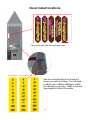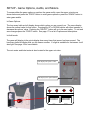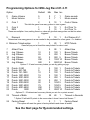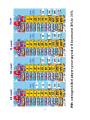
1
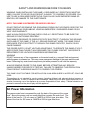
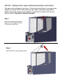
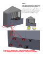
OWNERS AND SERVICE MANUAL
INNOVATIVE CONCEPTS IN ENTERTAINMENT INC.
10123 MAIN STREET, CLARENCE, NY 14031
SERVICE: 1-716-759-0360
FAX: 1-716-759-0884
E-MAIL: [email protected]
WEBSITE: www.icegame.com
2
Table of Contents
Safety, Warnings, and Power Requirements
Game Introduction and setup advisory
Setup
Assembly
Cages already attached, start here.
Cabinet is in two pieces, start here.
Optional Marquee install instructions.
Decal Install Locations
Game Options
Accounting
Error Codes
Score Sensor Layout
Playfield Service
Illegal Ball Sizes
Service
Main board access
Power supply access
PLL bulb replacement
Ball count sensor
Score sensors
Power supply troubleshooting
Playfield display access and replacement
Conveyor
Marquee bulb replacements
Schematics
Spares
Graphic Location and Part Numbers
Warranty
Rev H - 1.30.13
4
5
6-9
10-16
17-22
23
24
26
27
28
29
30
31
32
33
36
37
38
39
40
45
46
47
Milk Jug Toss
3
SAFETY AND WARNINGS BEFORE YOU BEGIN
WARNING: WHEN INSTALLING THIS GAME, A GROUNDED A.C. RECEPTACLE MUST BE
USED. FAILURE TO DO SO COULD RESULT IN INJURY TO YOURSELF OR OTHERS. FAILURE TO USE A GROUNDED RECEPTACLE COULD ALSO CAUSE IMPROPER GAME OPERATION, OR DAMAGE TO THE ELECTRONICS.
NOTE: THIS GAME IS INTENDED FOR INDOOR USE ONLY.
DO NOT DEFEAT OR REMOVE THE GROUNDING PRONG ON THE POWER CORD FOR THE
SAME REASON AS GIVEN ABOVE. USING AN IMPROPERLY GROUNDED GAME COULD
VOID YOUR WARRANTY.
HAVE A QUALIFIED ELECTRICIAN CHECK YOUR A.C. RECEPTACLE TO BE SURE THE
GROUND IS FUNCTIONING PROPERLY.
THIS GAME IS DESIGNED TO DISSIPATE STATIC ELECTRICITY THROUGH THE GROUNDING PLANE OF THE GAME. IF THE A.C. GROUND DOES NOT WORK, THE GAME COULD
DISCHARGE STATIC ELECTRICITY THROUGH THE GAME CIRCUITRY, WHICH COULD
CAUSE DAMAGE.
THE POWER SUPPLY IS NOT VOLTAGE ADJUSTABLE. TO OPERATE THE GAME AT VOLTAGES OTHER THAN THOSE IT WAS DESIGNED FOR. PLEASE CONTACT OUR SERVICE
DEPARTMENT FOR VOLTAGE CONVERSION INFORMATION.
WARNING
DO NOT remove any of the components on the main board (e.g. compact flash and eproms)
while the game is powered on. This may cause permanent damage to the parts and the main
board. Removing any main board component part while powered on will void the warranty.
ALWAYS REMOVE POWER TO THE GAME, BEFORE ATTEMPTING ANY SERVICE,
UNLESS NEEDED FOR SPECIFIC TESTING. FAILURE TO OBSERVE THIS PRECAUTION
COULD RESULT IN SERIOUS INJURY TO YOURSELF OR OTHERS.
THIS GAME IS NOT SUITABLE FOR INSTALLATION IN AN AREA WHERE A WATER JET COULD BE
USED.
This appliance is not intended for use by persons (including children) with reduced physical, sensory or
mental capabilities, or lack of experience and knowledge, unless they have been given supervision or instruction concerning use of the appliance by a person responsible for their safety. Children should be supervised to ensure that they do not play with the appliance
AC Power Information
The games main fuse is accessed through the back of the game at the power
mod. Above the power cord is a small panel that contains the main fuse. The
value of the fuse for 110 volt users is 6 AMPS at 250Volt type slow blow. The
value of the fuse for 220 users is 3 AMPS at 250Volt type slow blow.
4
Game Introduction:
The all time carnival hit is now a redemption game. Players skillfully toss the balls into the milk jug or surrounding holes to win
tickets. The interactive “Carny” voice heckles and entertains
players, while they shoot for the Super Bonus by getting all the
balls in the jug.
STOP– Important setup info:
Your game can be configured in different ways. We have included decals that you
need to apply to match your desired settings. Please read all of the setup sections
and programming recommendations before you begin to assemble your game. The
Graphic decals can be applied at any time and can be changed later if desired.
5
SETUP - Shipped with cages attached assembly instructions.
The game can be shipped in two ways. Follow these Instructions if your game was
shipped with both the front half, back half, and cages completely assembled together and only the canopy is not attached. If your game is split in half, see the
section entitled “Separated Cabinet Assembly”.
Step 1:
Remove ties that hold the upper
supports to the shipping 2x4 and
lift the upper supports up.
Step 2:
Raise the bars to their upright position.
6
Step 3:
3/4”
1”
1”
Attach the upper back supports to the front back supports using the supplied hardware as shown.
At this time attach the earth ground wire to the grounding lug at the light. Connect the AC harness for the light fixture. Tighten all hardware. It is recommended to use a long extension when
attach the Allen bolts.
7
Step 4:
Before proceeding it is recommended to apply the decals to this
before installing. See page 18 for recommended settings. Attach
the upper bonus Jug sign using the self tapping Robinson screws
following the predrilled holes shown below.
Step 5:
Attach the upper marquee using
the self tapping Robinson
screws following the arrows
shown. Only one side is shown
for clarity.
8
Step 6:
Finally raise the back end of the game by twisting the back leg levers counter-clockwise. It is
important not to have the game totally leveled
but instead, have the back slightly raised
enough so that the balls can return to the conveyor easier. If you find that your balls are getting hung up when returning to the conveyor,
you do not have the back raised enough.
NOT LEVEL
LEVEL
If installing a marquee, see “Optional Marquee Installation”.
If not installing a marquee, proceed to “Decal Install locations”.
9
SETUP - Separated cabinet assembly instructions
If your game has been shipped with the back and front separated, follow these instructions first.
Step 1:
Position the two halves as shown and on the left side attach the signal wire harnesses and on the
right side attach the AC harness. Now slide the two halves together.
Step 2:
Using the provided latch tool, latch the front half to the back half by inserting the wrench into the
hex holes and turning clockwise.
Latch tool
10
Step 3
Slide the cages down and inside the bottom cabinet.
Attach the cages to the cabinet using hat nuts on the
outside and 1/4-20 bolts on the inside to the two locations shown below. DO NOT TIGHTEN AT THIS TIME.
Hat Nuts go on the outside
Hat Nuts go on the outside
Using one hat nut on the outside and the shorter
1/4-20 Allen on the inside . A tool is provided in
the parts package.
DO NOT TIGHTEN AT THIS TIME.
Now install the remaining hat nuts and 1/4-20
bolts.
Hat Nuts go on the outside
DO NOT TIGHTEN UNTIL EVERY BOLT HAS
BEEN INSTALLED.
This will allow you to align the cage better.
Now tighten all bolts.
11
Step 4
Attach the upper support and the proximity sensor to the cabinet using two
1/4-20 bolts on each side.
The proximity sensor can be found in
the parts package located in the cash
box. Be sure to angle the sensor so that
it points to the Milk Jug which should be
about a 45 degree angle.
DO NOT PLUG SENSOR HARNESS
INTO SENSOR WITH GAME POWER
APPLIED.
DAMAGE MAY OCCUR TO SENSOR.
The bolts are attached from the inside
as shown in the circles.
Attach the sensor wire harness
to the sensor. The path of the wire
should travel along the
front left channel.
Step 5
Run the proximity sensor harness inside down the left side of the front cage channel and attach
the plastic trim on both sides. Attach the two plates with the square screws to cover the center
trim.
X’s 2
X’s 6
3”
12
Step 6:
Remove ties that hold the upper
supports to the shipping 2x4 and
lift the upper supports up.
Step 7:
Raise the bars to their upright position.
13
Step 8:
3/4”
1”
1”
Attach the upper back supports to the front back supports using the supplied hardware as shown.
At this time attach the earth ground wire to the grounding lug at the light. Connect the AC harness for the light fixture. Tighten all hardware. It is recommended to use a long extension when
attach the Allen bolts.
14
Step 9:
Before proceeding it is recommended to apply the decals to this
before installing. See page 18 for recommended settings. Attach
the upper bonus Jug sign using the self tapping Robinson screws
following the predrilled holes shown below.
Step 10:
Attach the upper marquee using
the self tapping Robinson
screws following the arrows
shown. Only one side is shown
for clarity.
15
Step 11:
Finally raise the back end of the game by twisting the back leg levers counter-clockwise. It is
important not to have the game totally leveled
but instead, have the back slightly raised
enough so that the balls can return to the conveyor easier. If you find that your balls are getting hung up when returning to the conveyor,
you do not have the back raised enough.
NOT LEVEL
LEVEL
If installing a marquee, see “Optional Marquee Installation”.
16
Optional Marquee Installation
Step 1:
Remove the left side display plate and
then the plastic trim from the front of the
game. Do not discard the three bolts.
Do not discard the display Plate.
Discard the 2 Square bit screws as they
are not needed.
X’s 3
X’s 2
3”
Step 2:
On the second game remove the right side display plate and
plastic trim piece from the front of the game. Do not discard
the three Allen bolts. Do not discard the display Plate.
X’s 2
X’s 3
3”
Step 3:
Attach one of the L-shaped spacers to the left side of a
game using four 1 1/2” wood screw and the other Lshaped spacer to the right side of the other game. Mount
the spacer flush to the outside of the cabinet.
No spacer is used in back of game.
Screw wood screws in these holes.
Mount flush
17
Optional Marquee Installation
Step 4:
Drill a one inch hole on the same side that you attached a spacer to if your game doesn’t have a
hole already present. You may have to pull the star decal back to confirm the present of the hole.
This hole is used to route the phone cord that is installed later on. Refer below for measurements.
22 1/2”
18”
Step 5:
Position the two games as shown and slide
the two games together. It is not critical that
the games be 100% parallel to each other,
they can be off at the back by up to a few
inches. The front needs to be flush in order
for the marquee mount to attach properly.
Both games need to be at the same level in
front.
18
Optional Marquee Installation
Step 6a:
Place the marquee assembly so that the bottom groove is at an angle as shown below. The fit is
tight and will require a little force to bring the games into alignment. Once the marquee assembly
is firmly resting at the bottom of the groove, push the top flush with the cabinet. Before fully resting the marquee against the cabinet, insert the canopy side flaps into the slots circled below at the
top of the plastic face. Do not pinch the canopy flaps behind the marquee. It will result in a unfinished look. Also pay attention to the wire harnesses so that you do not pinch them against the
cabinet cages.
SLOTS
Groove
19
Optional Marquee Installation
Step 6b:
Attach the marquee to the cabinet using the bolts you had removed in step 1. The bolt locations
are circled below. Re-attach one display plate you took off in steps 1 or 2 of “Optional Marquee
Installation”. Use the two 8-32 x1 “ PPHMS screws supplied to attach the plate.
See “DECAL INSTALL LOCATIONS” to pick your plate decal if blank.
X’s 3
X’s 3
20
Optional Marquee Installation
Step 7:
Route the wire harness from the marquee to the left game through
the cage as shown in the picture. Drop the wires down the hole
shown with the arrow. Use a wire tie to attach the harness to the
cage. Now run a phone cord from the left game’s main board to the
right game’s main board through the hole in step 4. Open the bottom
drawer to access the main board. It doesn’t matter which phone connector you use, they are both the same.
PHONE
CORD
Step 8:
Remove the two Allen bolts shown below and remove the cover on both games. Located at the
right of the game is the AC plug, and in some units the data display plug for the marquee. See
the picture below, they are circled. Refer to the wiring schematic insert for further harness information.
NOTE: BOTH GAMES MUST BE SETUP EXACTLY THE SAME IN PROGRAMMING. EVEN
THOUGH THEY ARE LINKED THEY DO NOT SHARE INFORMATION BETWEEN EACH
OTHER.
21
Decal Install locations
Choose the decal that best suits your taste.
Use the correct decal for the amount of
money you wish to charge. You will need
to adjust your software settings to match
the values you use here. Refer to the next
few pages for further information.
22
SETUP - Game Options, Audits, and Meters.
To access either the game options or perform the game audits, open the upper coin door as
shown below and press the “PROG” button to enter game options or press the “DOWN” button to
enter game audits.
In Game Options:
The how many balls are left display shows which option you are currently on. The score display
shows the current value for that option. Pressing the UP or DOWN buttons will either increase or
decrease the options’ value. Pressing the “SELECT” button will go to the next option. To exit and
save changes press the “PROG” button. See page 17 for a list of options and descriptions.
In Audit mode:
The game will display in the points display how many times that sensor has been scored. The
how many balls left display tells you the sensor number. If a light is available for that sensor it will
also light. See page 18 for more details.
The coin meter and ticket meter is also located in the upper coin door.
This displays the option’s value.
This displays the option number.
PROG
23
SELECT
UP
DOWN
00000
00000
COINS
TICKETS
Programming Options for Milk Jug Rev 2.01-3.11
Option
Default
Min
Max Inc
0
1
Game Volume
Music Volume
5
3
0
0
7
7
1
1
Game sounds
Music sounds
2
Coin 1
2
0
10
1
Cost of Game
This tells the game how many pulses to start a game
3
4
Coin 2
DBV
1
4
0
0
10
10
1
1
# of Coin 1’s
# of Coin 1’s
These are multiplier lines, setting them to a value will give that many pulses on that line when
triggered
5
Discount
0
0
10
1
# of Games til +1
Determines how many games in a row needed to be purchased for a free game. 0 = disabled.
6 Minimum Tickets option
1
0
20
1
MTO Tickets
Game will pay out at least this many tickets if a value is set.
7
8
9
10
11
12
Attract Time
Jug 1 Bonus
Jug 2 Bonus
Jug 3 Bonus
Jug 4 Bonus
Jug 5 Bonus
1
10
25
50
250
500
0
0
0
0
0
0
90
100
250
500
1000
5000
1
1
1
5
10
50
Attract time
Bonus Tickets
Bonus Tickets
Bonus Tickets
Bonus Tickets
Bonus Tickets
Options 7-12 sets how many tickets you win by getting xx jugs.
13
14
15
16
17
18
19
20
21
22
Points
Points
Points
Points
Points
Points
Points
Points
Points
Points
0-250
251-750
751-1500
1501-2000
2001-2500
2501-3000
3000-3500
3501-4000
4001-4950
5000
3
5
10
15
25
30
50
75
250
500
0
0
0
0
0
0
0
0
0
0
100
100
100
100
250
250
1250
1250
1250
2500
1
1
1
1
1
1
5
5
5
10
Points to Tickets
Points to Tickets
Points to Tickets
Points to Tickets
Points to Tickets
Points to Tickets
Points to Tickets
Points to Tickets
Points to Tickets
Points to Tickets
Options 13 - 22 determines how many tickets you win for xx points scored.
23
Timeout of Balls
30
30
60
1
Timeout in Seconds
** Option 23 will add 50 points to the score when it doesn’t see a ball thrown. **
24
Factory Reset
0
0
1
1
Factory Reset
This option will reset the game to factory defaults and clears all audits.
See the Next page for Recommended settings.
24
25
With average skilled players your payout will be around 30% to 35%
Milk Jug Accounting Version 2.00 – 3.12/NJ/NJS/D/CEC
Milk Jug accounting is entered by pressing the far right (down) button when NOT in programming mode. The game will cycle through each of the different locations and will wrap to the beginning. To zero the values press the third button (up) as counting from the left. When zeroed
the game should exit accounting to signify that you have zeroed the values. To exit without zeroing the values press the same button used to enter into accounting mode.
Most locations will flash where the value showing is coordinated with. The numbers are from
bottom left to top right and then Jug, etc.
Number
1
2
3
4
5
6
7
8
9
10
11
12
13
14
15
16
17
18
19
20
21
22
23
Locations
Lower Playfield Left (50)
Lower Playfield Second from Left (50)
Lower Playfield Second from Right (50)
Lower Playfield Right (50)
Lower Playfield Middle Row Left (100)
Lower Playfield Middle Row Middle (250)
Lower Playfield Middle Row Right (100)
Lower Playfield Top Row Left (150)
Lower Playfield Top Row Middle (50)
Lower Playfield Top Row Right (150)
Upper Playfield Left (200)
Upper Playfield Second from Left (250)
Upper Playfield Middle (300)
Upper Playfield Second from Right (250)
Upper Playfield Right (200)
Jug (1000)
Zero Jug Games
One Jug Games
Two Jug Games
Three Jug Games
Four Jug Games
Five Jug Games
Tilted Games
NOTE:
To prevent hiccups in the game the results of the game are stored when the game is idle.
If there are constant credits in the game then the above values will not be able to store into nonvolatile memory and will be lost if power is removed. So to insure that all values are saved the
game should be in attract for 20 seconds.
For a quick check of sensors, any value at 0 should be checked.
26
Milk Jug Error Codes Version 2.00 – 3.12/NJ/NJS/D/CEC
Error
1
2
3
4
5
6
7
8
9
10
11
12
13
14
15
16
17
18
19
20
21
22
23
24
25
26
27
28
29
30
31
32
Reason
Ticket Error
Compact Flash Error
Error Sensor Hole 1
Error Sensor Hole 2
Error Sensor Hole 3
Error Sensor Hole 4
Error Sensor Hole 5
Error Sensor Hole 6
Error Sensor Hole 7
Error Sensor Hole 8
Error Sensor Hole 9
Error Sensor Hole 10
Error Sensor Hole 11
Error Sensor Hole 12
Error Sensor Hole 13
Error Sensor Hole 14
Error Sensor Hole 15
Jug Sensor 1
Jug Sensor 2
Ball Dispense Sensor Front
Ball Dispense Count
Left Zero Sensor
Coin 1 Switch stuck
Coin 2 Switch stuck
DBV Switch stuck
- Not Used Cheat Sensor 1 stuck
Right Zero Sensor
Program button stuck
Select button stuck
Up button stuck
Down button stuck
Halt Game
N
N
N
N
N
N
N
N
N
N
N
N
N
N
N
N
N
Y
Y
Y
N
N
N
N
N
N
N
N
N
N
Upon power up the error codes will cycle for 5 loops displaying any error codes that are currently active. The game will then continue on, unless a Jug error code exists.
** The high score display will show a 2000 as its current highest score if a error is detected on power up.
** A high score of 1050 means the game has just been powered on or has rebooted.
27
Score Sensor Layout
Jug
2
Jug
1
Bottom of Playfield
15
11
12
8
10
9
5
1
14
13
7
6
2
3
4
Top of Playfield
Left Zero Sensor
28
Right Zero Sensor
Playfield Service
The playfield flips open for easy access to all score sensors and it is also how you access the
illegal ball trap door.
Remove the two hat bolts shown below using a Allen wrench. ** WARNING** Be sure that no
persons fingers finger’s are holding onto the side cages when raising or lowering the playfield.
Lift the playfield all the way as far as it will go, the shocks will keep the playfield up in the air during servicing.
Remove these hat bolts
using a Allen wrench
29
Illegal Ball Size Access Door
During game play if any balls used is not of the correct size it will fall into the games’ “illegal ball
trap” storage located under the playfield. To access this and remove the balls, follow the instructions in the section titled “Play field Service”. Using your keys, unlock the plastic cover and remove. You can now remove the balls. Replace cover and close the playfield. The diagram below shows the cover. Side of cabinet removed for clarity.
30
Accessing the Main Board and Power Supply
To gain access to the main board, open the bottom door and pull the drawer out. There you will
find the main circuit board and power supply.
BOARD
PLL Bulb Replacement
Attached to the back door are 3 PLL bulbs that provide back lighting to the cabinet. To replace a
defective bulb, open the back door, remove the bulb clip, and press the red button to release the
bulb from the socket. To install a PLL bulb, push the bulb down onto the socket, DO NOT SLIDE
THE BULB INTO THE SOCKET, until you hear a “CLICK” noise from the socket. Now re-attach
the bulb clip to complete the bulb replacement.
Must click when pushed down!
31
Ball Count Sensor Replacement
The game will not dispense balls if this sensor is not
working. .
32
Score Sensor Replacement
There are three types of score sensors used in Milk Jug. MJ2037X, MJ2038X, and MJ2038SX. Following
the instructions in section “Play Field Service” to gain access to these sensors. Both sensors mount the
same way as shown. See Wiring insert for location of sensors or look below. Last number of part shown.
8
8
8
8
MJ2037X
33
8
7
7
7
8
8
7
8S
7
7
7
Score Sensor Replacement
MJ2038X and MJ2038SX
34
35
8V
D3
LED
D7
LED
Enable
D2
LED
64Ω
R5
D6
LED
8V
G
O
D1
LED
I
7808 VR1
D5
LED
D4
LED
40Ω
R1
.1MFD
C5
12V
+
8V
100MFD
16V
C6
D
Q8
SFH300
Q7
SFH300
Q6
SFH300
Q5
SFH300
Q4
SFH300
Q3
SFH300
Q2
SFH300
Q1
SFH300
10
9
8
7
6
8V
5
4
3
2
RN1
100KΩ
-
-
-
-
-
-
-
5 +
6
3 +
2
5 +
6
3 +
2
5 +
6
3 +
2
5 +
6
3 +
2
U5
LM393B
7
U5
LM393A
1
U4
LM393B
7
U4
LM393A
1
U3
LM393B
7
U3
LM393A
1
U2
LM393B
7
U2
LM393A
1
8V
D8
LED
500Ω
R6
8V
Enable
47KΩ
R3
47KΩ
R2
12
U2
U1
Signal
Ground
Key
Power
P1
.1MFD
C2
.1MFD
C1
U3
U4
4
8
8V
4
8
8V
.1MFD
C3
.1MFD
C4
PR2039AX
REV 2
+V when idle
0V when blocked
5
4
3
1
4
8
8V
4
8
8V
Power Supply Access
SUZO HAPP Power Pro
The power supply is a IA2010 and is accessed from the front of the game through the bottom
drawer. See the section “Accessing the main board and power supply”.
ADJ
ON
Turn clockwise to increase power if low
Power on status
+12
10A
+ 12 Volts DC - 10 Amps; orange
+12V
10A
+ 12 Volts DC - 10 Amps ; orange
GND
DC Ground - Black
GND
DC Ground - Black
GND
DC Ground - Black
Input
95V - 135VAC
3.2A
190V - 250VAC
1.6A
47Hz - 63Hz
FG
AC Earth Ground - Green with Yellow
AC
(L)
AC Line - Black or Brown
AC
(N)
AC Neutral - White or Blue
Checking DC Voltages
Volt test with the volt meter set to DC voltage. The +12 output can be adjusted by turning
the adjustment screw of the power supply. Adjust to as close to +12 as possible. Increasing the +12. The voltage range can be plus or minus 5%.
Turn to DC voltage check
Positive Probe:
Connect to +12V on power supply
(orange wire to power supply)
Ground Probe:
Connect to GND on power supply
(Black wire to power supply)
36
Replacing Playfield Displays
Open the back door and remove the seven nuts that hold the display panel to the cabinet.
Disconnect the display harnesses and remove the entire assembly.
Remove nuts
shown with
arrows
Lay the assembly on its back and remove the plastic standoffs to remove the display. Assembly
in reverse order.
Small display is a DA2133X.
Large display is a RB2032X
Remove plastic
standoffs to remove
displays.
37
Safety Conveyor Sensor - RB2009BX
To access the safety conveyor sensors you only need to remove the front panel.
Sensors
Conveyor Access
Remove the bolts shown with the arrows. Now remove the cover. The motor assembly is ICE
part MJ2009X. The gearbox head is ICE part MJ2009A.
Tension
Adjustment
Tension
Adjustment
Motor
38
Optional Marquee - Bulb and Bonus display replacement
Remove the front panel of the marquee by unscrewing the screws at the locations shown with the
circles below.
To replace the display, remove the four plastic stand off nuts that hold the display to the marquee.
To replace a bulb, remove the plastic clip and press the red button to release the blub. Be sure to
push down on the bulb until it clicks when inserting a new bulb into the PLL socket.
Must click when pushed down!
39
Main Schematics
40
Main Schematics
41
Main Schematics
42
Main Schematics
43
Main Schematics
44
Spares List
Electronics:
RB2032X
DA2133X
PP250X
E00377
E00670MJX
MJ2007X
MJ2009A
MJ2009X
MJ2037X
MJ2038X
MJ2038SX
RB2009BX
AR2007
IA2010
2111
MJ2034X
E00156
HH5005
CX8384X
E00414MJX
NA2032X
PR2039AX
8982RBX
E00418MJX
E02295
Where used?
Big display board located behind playfield.
Small display board located behind the playfield.
PLL bulbs located in the marquee and behind the playfield.
Spot light used at top of game canopy.
Workhorse 8 ballast used behind the playfield.
Power module (6amps) used in back of game, incoming AC.
Gearbox head for motor used in the conveyor.
Motor assembly used in the conveyor.
Score sensor (see playfield score layout).
Score sensor (see playfield score layout).
Score sensor (same as MJ2038X but with a straight connector)
Optical sensor, used in ball return and 50 point score sensors.
Speakers
12 volt power supply used to power game.
Ball conveyor relay.
Main board with CPU board.
Rocker switch
Ticket dispenser, used in front door assembly.
Marquee ballast, workhorse 5, used in marquee.
Blue LED strip.
Marquee display
Reflective sensor board used in ball conveyor.
Pir sensor located in the top, left front of cabinet.
White LED strip.
6 amp 250V slo blo mdl fuse
Mechanical:
211
BW2017
BW2018
CG1052
CG3019
T-molding blue
Plastic clip for PLL bulbs
Plastic Bulb support
3” swivel caster
Cage retainer cap
45
46
Graphic Locations and Part Numbers
WARRANTY POLICY
I.C.E. Inc warrants all components in new machines to be free of defects in materials and workmanship for the
period listed below:
■ 180 days on Main PCB’s, Computers & Motors
■ 1 year on all LCD monitor panels
■ 90 days on all other electronic and mechanical components
■ 30 days on all I.C.E. repairs and parts purchases
I.C.E. Inc shall not be obligated to furnish a warranty request under the following conditions:
■ Equipment or parts have failed through normal wear and tear
■ Equipment has been subjected to unwarranted stress, abuse or neglect
■ Equipment has been damaged as a result of arbitrary repair/modification
Products will only be covered under warranty by obtaining an I.C.E. authorized RMA #. To obtain an RMA #
please provide I.C.E. tech support with the game serial # or original I.C.E. invoice # and a detailed description
of the failure or fault symptoms.
I.C.E. Inc will assume no liability whatsoever for costs associated with labor or travel time to replace defective
parts. All defective warranty covered components will be replaced with new or factory refurbished components equal to OEM specifications.
I.C.E. Inc will cover domestic UPS ground, or comparable shipping costs during the warranty period. International or expedited shipments are available for an additional charge. To obtain credit defective parts must be
returned to I.C.E. Inc, at the customer’s expense, within 30 days. After 30 days a 15% re-stocking fee will apply to all returns.
ICE distributors are independent, privately owned and operated. In their judgment, they may sell parts and/or
accessories other than those manufactured by I.C.E. Inc. We cannot be responsible for the quality, suitability
or safety of any non-I.C.E. part or modification (including labor) that is performed by such a distributor.
Innovative Concepts in Entertainment
10123 Main St.
Clarence, NY 14031
Phone #: (716) - 759 – 0360
Fax #: (716) – 759 – 0884
www.icegame.com
47