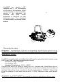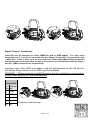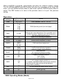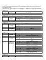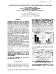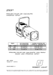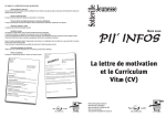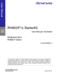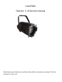
1
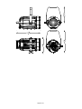
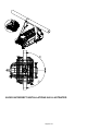
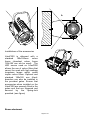
LitesF200
Owners ‘s & Service manual
Read this manual totally and carefully follow all the instructions contained. File this
manual for future use.
It is essential to read all the information contained to ensure installation, service and
full operation of the LitesF200
All operations must be accomplished, handled and carried out by qualified personnel
only. Not complying with given notice will void warranty and will free manufufacturer
from any liability/responsability
http://www.ilites.eu
Pagina 2 di 8
Unpacking
Unpack the carton and gently remove LitesF200 from the box. Ensure LitesF200
received is integer from origin in all its components.
In the event the LitesF200 shows any damage, do not use it and contact immediately
your transporter as well as your seller.
Items in the carton consist of:
− LitesF200 luminaire
− Colour frame
− Blue Neutrik PowerCon connector
− This owner's and service manual
Safety information for the use of the LitesF200 as well as its periodical
maintenance”
‒
‒
‒
‒
‒
‒
‒
‒
‒
‒
‒
‒
‒
‒
LitesF200 is for professional use only and NEVER for domestic use therefore
refrain from this latter utilisation.
Users must scrupulously comply with information that follows, any other use in
contrast will void warranty and will free the manufacturer of any sort of
responsibility and liability.
Never use LitesF200 on any flammable surfaces.
Minimum distance from any flammable source is of 0.25m.
Minimum throw distance from illuminated surface: 0.5m.
Installation of the unit(s) must be secured with adequate clamps, safety cords,
nuts and bolts to bear the weight of the whole unit(s)
Always Power LitesF200 to safety circuit breakers. LitesF200 must NOTand
CAN NOT be operated via Phase Control Dimmer.
Install LitesF200 in ventilated ambient which temperature must not trespass
35°C
Some outer parts of the LitesF200 can reach temperatures of up to 60C° when
in operation.
LitesF200 must be fitted with protection shields (Lenses)
On no account, directly or indirectly, LED must be touched
Always disconnet power, (always double check that power is off) before any
Service/Operation of the unit.
LitesF200 is rated Class I.
Earth connection is MANDATORY!
An essential and periodically throughout cleaning of the LitesF200 is recommended.
This practice avoids that layers of dust and other impurities jeopardise and reduce
the correct operation of the unit. Lenses must be cleaned to remove layers of dust
that may impede and or reduce the passage of the light through the lenses. The
correct and periodically maintenance keeps also fans and vents clean to keep the
LitesF200 in its best performance conditions. Never touch the Yellow core of the LED
Pagina 3 di 8
both directly or indirectly nor use solvents that can damage the LED irremediably.
Protection shields if battered, must be replaced with new ones (Lenses)
CE APPROVALS
The LitesF200 meets EMC 89/336/CEE, 92/31/CEE, BT72/23/CEE, 98/68/CEE
requirements.
The LitesF200 complies with EN50419 (Rohs) and 2002/96/EC (WEEE) norms.
WARRANTY
A 12-month warranty is granted on the LitesF200 from its purchase’s date. Warranty
covers fabrication defects only, unit will not be replaced but will be 100% fixed.
Warranty is immediately voided if the LitesF200 has not been handled by qualified
personnel. Any improper and unauthorised use, such modification(s) or
misapplication of the unit will also void the warranty of the product(s). Silver colour
label showing technical data and serial number, if removed or if data are impaired to
render details illegible, will immediately void the warranty.
Pagina 4 di 8
Technical specifications
Power Supply:
Maximum power consumption
100/240V̴~ 50/60Hz (autosetting)
200W (Citizen CLL050-CLL052) cos ø
0,98
Maximum power consumption
140W (Bridgelux BXRA/Vero) cos ø
0,98
Stand-by power consumption
5W
LED Colour temperatues and CRI : ASK INFORMATION at [email protected]
Fresnel Lens: Ø 150mm
Colour frame dimensions: 195x185 mm (the use of standard 185x185mm colour
frame is totally acccettable)
Aluminium die-caste body to maximize heat dissipation
Operating temperature range:
-15°C + 35° C
Maxium temperature on the LitesF200
+60°C
Weight of the unit: Kg 6,9
Worm-gear beam adjustment on standard Lites200F/ Automatic zoom on
LitesF200Zoom
Rear handle for good grip of unit ; side-lock on mounting yoke to adjust and set unit
to position.
Beam angle: 18°-60°
Working position: +90°/-90° on vertical axe
Protection rating: IP 20
DMX 512 , RDM, Protocols (wireless on request)
Neutrik powercon IN & OUT connectors
Neutrik XRL5 IN & OUT signal connectors
4-digit display
Manual operation via 4-digit display
Idle fan mode for totally silent use of the unit.
Adjustable LED frequency
Selection of two LED dimming curves
Comply with
Dimensions: see figure
Pagina 5 di 8
Pagina 6 di 8
Lites200F installation
Lirtes200F is delivered with a robust yoke which hosts 3 x 12 mm mounting holes.
The use of an adequate G-clamp to sustain at least twice the weight of the
Lites200F (Lites200F weighs 7,9 kg) and/or M10 screw is mandatory. The use of
safety chain(s) to sustain twice the weight of the Lites200F is also mandatory, the
safety chain adds more protections to users and third-parties. Eye-lid for the safety
chain is provided on the LitesF200. (see Fig)
The Lites200F yoke revolves on 360° on the projector’s axis. Lites200F can be
installed +-90° on the vertical axis. (see Fig.). Best Lites200F’s perfomrances are
achiieved if unit is installed as shown in the illustrations that follows. (never install
LitesF200 upsidedown, illustrations that folllows show installation positions that must
be avoided) . Incorrect installation(s) can, immediately or in short/long terms,
jeopardise the correct operaton of the LitesF200. Incorrect installations may voide
the warranty of the unit.
.
Pagina 7 di 8
90
°
°
90
AVOID INCORRECT INSTALLATIONS AS ILLUSTRATED
Pagina 8 di 8
A
Installations of the accessories
LitesF200 is delvered with a
standard
195x185mm
colour
frame (standard colour frame
185x185 can als be used). The
LED source used on LitesF200
allows the use of colour filters that
cannot be used with high wattage
tungstene lamps which would
impair colour filters. Optional and
standard 185x185 mm 4-leafbarndoor can also be installed in
the provided gates. Ensure that
accessories when installed on the
LitesF200 are securely fitted in the
gates and that are triggered and
secured
by
the
spring-lock
provided. (see figure)
Beam adustment
Pagina 9 di 8
Lites200F can revolve +-90°
upwards and +- 90° donwwards
on the axis of the luminaire. When
correct position is set to position,
secure it by tightneing the
provided
side
knob.
Beam
adjusment is achieved via rear
Helicoidal screw. Turn clockwise
to narrow beam, conversely beam
widens.
-
+
ZOOM
Connection to mains
WARNING ! Installation(s) must be accomplished, handled and carried out by
qualified personnel only and must comply with all norms in force in the
installation's country
LitesF200 is supplied with a free Blue Neutrik PowerCon plug that must be wired using
a 3x1.5mm² lead , additional specifications include:
‒
Operating Voltage: 300/500V
‒
Test Voltage: 2KV
‒
Operating Temperature: -10°C / +100°C
Connect blue wire to N terminal, brown wire to L terminal and Yellow/Green wire to
earth terminal. (see also illustration fig) Ensure connections to safety circuit breaker at
all times. Daisy chain of up to maximum 8 units if connected to 230VAC. Daisy chain
of up to maximum 4 units when connected to 110VAC. Maximum daisy chain length:
25m.
WARNING: LitesF200 CANNOT be powered by using an angle phase dimmer pack
Pagina 10 di 8
POWER IN
POWER OUT
A
Signal Control Connection
LitesF200 can be operated via either DMX512A and or RDM ready . For dasy chain
connection use a -2 x 0,5 mm² size lead wire plus shield. Connect Pin 1 to ground, 2= data
– while Pin 3 = data +. Pins 4 & 5 are not connected. Ensure that DMX wires and shield do
not interfere,nor touch each other as well as they must not touch/interfere with the body of
the unit . (DMX connectors are not provided)
Important note: when DMX is available a red dot will illuminate on the left hand of
the display.When red dot is off no DMX signal is available.
WARNING ! Before powering LitesF200 ensure that all installation(s) procedure(s)
have(s) been properly set and accomplished.
XLR5
connection
Le Descrip
ads tion
1 GND
2 DMX-
DMX IN
DMX OUT
3 DMX+
4 NC
5 NC
Projector mode settings
Pagina 11 di 8
UP
Enter
Down
Esc
When LitesF200 is powered, setup-display will show the software release version
The UP, DOWN, ENTER and ESC buttons will allow the operations of the LitesF200
menu. UP and DOWN buttons allow to scan menu options, ENTER button allow to
select. The ESC button is to retun to the previous menu or to quit the previous
setting.
Menu items
Displayed
message
Addr
Mode
Allowed or
displayed values
001..510
1 ch
2 ch
3 ch
4 ch
5 ch
Man
0..255
drUt
LEdt
PUM
..°C
..°C
0..100%
FAST
MED
SLOW
SMOO
GAMM
LInE
qUAd
booS
Off
on
PoS
AA
VV
StbY
Off
on
dEF
TiML
TiMU
SoFt
Mode
DMX address : as of 1 to 510
DMX Operating mode (see next page)
Manual light output adjustment (This is possible even if
no DMX is present). Adjusted value will be stored on
the internal permanent memory
Shows driver operating temperature
Show led operating temperature
Shows current led power (0-100%)
DMX data Speed adjustment
Dimmer profile selection:
- LinE for linear dimming regulation
- qUAd for tungsten lamp emulation)
Boost selection:
off = maximum led power at 90%
on = maximum led power at 100%
I Display orientation selection:
AA = normal
VV = inverted
Standby display activity:
off = display always switched on
on = display switched off after few seconds of buttons
inactivity (only the right side dot will be lighted to
indicate DMX availability)
Off
on
..h ..
..h ..
ON Will restore the default factory values
Shows LED life
Shows HPLed life
Shows Software version
DMX Operating Modes (Mode)
Pagina 12 di 8
LitesF200 provides with different DMX operating modes ensuring the ideal use of
the DMX universe
Shutter/strobo, 8/16 bit dimmer, fan speed and LED frequence are all adjustable
Mode a 1ch
Ch
1
functon
dimmer
mode a 2ch
Ch
1
function
shutter
2
mode a 3ch
Ch
1
2
3
mode a 4ch
Ch
1
dimmer
functon
shutter
dimmer
Fan speed
Function
shutter
2
3
dimmer
Fans
4
LED
Frequency
Modulation
mode a 5ch
Ch
DMX Values
0..255
Light output: 0=Off, 255=Maximum Power
DMX Values
0-9
10..255
0..255
off
Strobe effect from slow to fast
Light output: 0=Off, 255=Maximum Power
DMX Values
0-9
10..255
0..255
0..24
24..255
off
Strobe effect from slow to fast
Light output: 0=Off, 255=Maximum Power
Fans off
Fan speed from slow to fast
DMX Values
0..9
10..255
0..255
0..24
24..255
0..24
25..49
50..74
75..99
100..124
125..149
150..174
175..199
200..224
225..255
off
Strobe effect from slow to fast
Light output: 0=Off, 255=Maximum Power
Fans off
Fan adjustement from minium to max
value
PWM Frequency 5,1KHz
PWM Frequency 5,2KHz
PWM Frequency 5,3KHz
PWM Frequency 5,4KHz
PWM Frequency 5,5KHz
PWM Frequency 5,6KHz
PWM Frequency 5,7KHz
PWM Frequency 5,8KHz
PWM Frequency 6KHz
PWM Frequency 610Hz
function
DMX Values
Pagina 13 di 8
1
2
3
4
5
shutter
dimmer
Fine
Dimmer
Fans
LED
Frequency
Modulation
(flickering)
0..9
10..255
0..255
0..255
0..24
24..255
0..24
25..49
50..74
75..99
100..124
125..149
150..174
175..199
200..224
225..255
off
Strobe effect from slow to fast
Light output: 0=Off, 255=Maximum Power
0..255 fine dimmer adjustment
Fans off
Fan adjustement from minium to max
value
PWM Frequency 5,1KHz
PWM Frequency 5,2KHz
PWM Frequency 5,3KHz
PWM Frequency 5,4KHz
PWM Frequency 5,5KHz
PWM Frequency 5,6KHz
PWM Frequency 5,7KHz
PWM Frequency 5,8KHz
PWM Frequency 6KHz
PWM Frequency 610Hz
Pagina 14 di 8
Error messages
In case of malfunction, the following messages may be shown:
LED ERROR : sympthon of a possible short-circuit on LED driver.
TEMPERATURE ERRor: sympthon that sensors have measured temperature below 15°C or failure on NTC- in such event LED will switch to off mode. Should any of the
above given messages occur, for precaution measures the LED will always switch to
off mode. Halt the unit immediately and refrain from the use of it and promptly contact
any authorized service centre.
Periodical maintenance
To ensure the correct LitesF200’s operations we suggest the following periodical
maintenance operations:
Remove dust or any kind of other dirty from the fans and loop-holes to ensure the
correct air flow
− Remove dust from lenses using a clean cloth. This maintenace will ensure the
maximum light efficiency
− Replace damaged protection screens and lenses when necessary
− Always handle LitesF200 gently and with care, do not drop, do not shake do not
cause shocks to the unit as it could damage it irremediably.
−
Do not touch nor clean the LED as well as the yellow area around it with solvents
Device disposal information
At the end of its life, LitesF200 must be disposed to an
appropriate electrical and electronic equipment waste collection
centre. Eco-friendly disposal, helps to avoid possible negative
impact on the environment and human health and promotes the reuse
and/or recycling of the materials making up the product. Illegal disposal
involves administrative sanctions provided by laws enacted.
Manufacture declines any sort of personal/corporate responsibility/liability for damages
caused by the inadequate use of the product as well as if unqualified personnel have
handled the product. Not complying with security norms/periodical maintenance as
Pagina 15 di 8
expressed in the owner's/service manual will also totally free personal/corporate
responsibility/liability.
Text, wordings, drawings, specifications, modifications and other changes of
this manual may apply anytime without notice. The specifications are not
binding.
Lites F 200 White 04/11/2013
rev.01
Pagina 16 di 8