Transcript
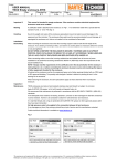
Scope :
User Manual
TNFCD/TNFAD Flashing Beacons
Date:
27.09.2011
Rev.
Checked by :
E.T.
B
Approved by
S.Gr.
Page :
1 of 1
Document no. :
23-TNF-5
Marking
An Ex-certification label is attached to the enclosure. Ref. examples in Fig 1.
Handling
Due to the weight and nature of the enclosures precautions have to be taken to avoid damages to the equipment
and the individual. The flamepaths on the Exd enclosure must be securely protected to avoid damage.
Installation/
Dismantling
When mounting the enclosure ensure that the mounting support is able to take the full weight of the enclosure. If
any twisting or bending of the enclosed bracket is likely, use washers or packing plates as necessary between the
mounting support and the bracket before the screws or nuts are tightened.
The beacons will be fixed to the bracket by using 2 ea M6 screws.
When connecting cables, ensure the incoming cables/wires are isolated from power sources.
Ensure that the glands used are securely tighten and that they are approved according to ATEX.
Termination of cable to be done according to termination label located inside the bottom lid, ref. fig.2.
Therafter connect the internal (alt. external ) earth connections.
Tighten the compression nut on the gland(s) used. All other openings to be blinded using an Ex ( ATEX )
approved blind plug.
Before the power source is connected ensure that the voltage of the source is the same as indicated on the label
on the beacon.
When removing the enclosure, the same precautions apply as those observed when mounting the enclosure.
Inspection /
Maintenance
TNFCD/TNFAD Flashing beacons are made of corrosion resistant materials.
We recommend that maintenance is performed in accordance with the IEC 60079-17/60079-1 standards.
If the flashing beacon needs to be opened, proceed as follow :
1.
Disconnect the power source.
2.
Unscrew the external fixing screw on the Exd part.
3.
Clean and inspect the theads ( flamepath ) on the bottom part and inside the tube.
4.
Inspect the O-ring on the bottom part. We recommend that this O-ring is replaced upon every opening of the
beacon. NOTE: new O-ring to be supplied by BARTEC TECHNOR.
5.
Before assembly, the O-ring and threads to be protected with copper grease or other approved greases.
6.
Connect the tube on to the bottom part, and assure that the unbrako fixing screw is firmly tightened.
If any damages are found, the enclosure should be put out of service and the manufacturer contacted.
Fig.1
Fig.2
The passing on and copying of this document and the use or communication of it’s contents are forbidden without express authority. Offenders are
liable to payment of damages. All rights are reserved in the event of the registration of a patent .
23-TNF-5_B User Manual TNFCD-TNFAD