1
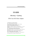
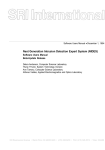
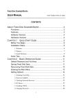
User Manual of SST-1200 GPS Time Synchronization System E-Point Electronics GmbH Please Please Please Please you. read the manual detailed before application. keep the manual. understand the content. contact us anytime if anything of our equipment doubts Contents 1. Purpose and Characteristics of the System ................................................... 1 1.1 Purpose ....................................................................................................................... 1 1.2 Characteristics ............................................................................................................. 2 2. Technical Data ............................................................................................... 4 2.1 Physical Parameters.................................................................................................... 4 2.2 Environmental Condition ............................................................................................. 5 2.3 Electromagnetic Compatibility ..................................................................................... 6 2.4 Power Supply .............................................................................................................. 6 2.5 Mean Time Between Failures (MTBF) ........................................................................ 7 2.6 Input and Output Interfaces for Time Signals.............................................................. 7 2.7 Data for Core GPS Receiver of Standard Clock Equipment....................................... 9 2.8 Data for Timing Precision of Output Signal ............................................................... 10 2.9 Interface Specification ............................................................................................... 12 2.10 Warning Signal ........................................................................................................ 17 2.11 Stability for the Precision of Internal Timing Clock when GPS is out of Synchronization ............................................................................................................... 17 2.12 Standard quoted ...................................................................................................... 17 3. SST-1200 GPS Time Synchronization System ............................................ 19 3.1 Configuration of SST-1200 GPS Time Synchronization System .............................. 19 3.2 Structure of Equipment and Introduction on Modules............................................... 21 3.3 Operating State Indication ......................................................................................... 43 3.3.1 Indicators for standard time synchronization clock ................................................ 43 3.3.2 Indicators for GPS satellite synchronization clock indicator .................................. 45 4. Equipment Installation and Operation Introduction ...................................... 46 4.1 Installation of Antenna ............................................................................................... 46 4.2 Installation Position of the Equipment ....................................................................... 48 4.3 Put into Operation...................................................................................................... 48 4.4 Installation of Lightning Arrester ................................................................................ 51 5. Failures and Maintenance of the Equipment ............................................... 52 5.1 Alarm.......................................................................................................................... 52 5.2 Holding and Switching of Time Signal ....................................................................... 52 5.3 Maintainability ............................................................................................................ 53 5.4 Safety......................................................................................................................... 53 5.5 Maintenance of the Equipment ................................................................................. 53 6. Attachment I Type Selection Table for SST-1200 Series GPS Time Synchronization System .................................................................................... 55 User Manual for SST-1200 GPS Time Synchronization System Page 1 SST-1200 GPS Time Synchronization System 1. Purpose and Characteristics of the System SST-1200 GPS Time Synchronization System is designed in accordance with Technical Specifications for Unified Clock System of East-China Power Grid, Technical Specifications for GPS Time Synchronism System of Transformer Substation in Guangdong Power Grid and Technical Principle and Operation Management Specifications for GPS Time Synchronization System of Shanghai Power Grid. It is composed of standard time synchronous clock and timescale signal extension set, applicable for panel composition combinedly or independently. Timescale signal extension set includes pulse, time message, DCF77, B code and NTP extension modules; the set can be combined according to real needs. By utilizing the synchronization signal (second) and time information of GPS (Global Positioning System) or IRIG-B (DC) code, the System can provide accurate time information and time synchronization signals for various electric power systems and automation equipment (such as dispatching automation system, microcomputer relaying protection equipment, failure oscillograph, event sequence recording device, remote control unit, computer data interchange net, lightning positioning system, etc.). 1.1 Purpose Main purposes of SST-1200 GPS Time Synchronization System are as the followings: 1. Provide standard time and time synchronization signals for electric power systems; 2. Work as a wall clock for electric power companies (electric power bureaus) of all levels and the corresponding dispatching stations, power plants and transformer substations etc. User Manual for SST-1200 GPS Time Synchronization System Page 2 1.2 Characteristics 1. High synchronization accuracy with external synchronization clock signal, with synchronization accuracy better than ±0.2µs. Adopt multiple synchronization sources self-adapting synchronization technology, with synchronization accuracy better than ±0.2µs. 2. Redundant structure. Support dual GPS hot standby and dual IRIG-B hot standby and adopt high-precision timing clock. Standard time synchronization clock can receive GPS and 1-channel IRIG-B code external synchronization signal together, which are standby to each other. Timescale signal extension set can receive 2-channel IRIG-B code external synchronization signals together, which are standby to each other. Master clock and signal extension set all adopt redundant structure to ensure the reliability and stability of GPS time synchronization system. 3. Modularization design, various output interfaces and convenience for use. The System can output IRIG-B (AM) code and IRIG-B (DC) code that comply with IEEE STD 1344-1995 Standard, as well as definable hourminute-second pulse idle contact and time message information; 12 channels can be included into one group by random combination. 2U equipment is capable for 60 channel outputs at most and 4U equipment is capable for 156 channel outputs at most. Adopt 4U 19” standard cabinet (applicable for panel composition independently), which provides convenience for the future extension of GPS time synchronization signals, with easy maintenance and management. 4. Dual CPU parallel processing time message output technology. Time message output adopts dual CPU parallel processing technology. The message sending time is timing edge of second (s), with an error no more than +0.2ms. 5. High-precision pulse output. User Manual for SST-1200 GPS Time Synchronization System Page 3 Pulse output adopts large pulse current generating circuit, which is helpful for optoelectronic isolation idle contact to output high-precision pulse signal with an error no more than 10µs. 6. High-precision timing clock Adopt closed loop control technique for high-precision timing clock, and the timing precision can reach 1µs/min. 7. Adopt IRIG-B (AM) code generating technique (without overshoot) to generate high-precision IRIG-B (AM) code, with a precision up to 5µs. 8. Support optical fiber or cable cascade input and output. 9. The signal receiving is with high reliability, free from the restriction of the area conditions in power station. 10. All signal output ports adopt photoelectrical isolation, and resistance to electromagnetic interference is up to Grade III. 11. Alarm contact output for monitoring the operational status of the System, which includes power supply failure alarm, external synchronization signal failure alarm and system self-checking abnormal alarm. 12. LCD indicates date, time and external synchronization information. 13. Function of power grid frequency measurement. 14. The multi-satellite system input and the seamless switching between different systems ensure the safety and reliability of time service system. At present, it supports GPS, CNSS and GLONASS. 15. Support NTP (Network Time Protocol), Version 4. 16. Applicable to more networking methods, standby methods, host & client methods, etc., with a flexible and variable networking mode. Adaptable to dual clock or multi clock standby, master-slave clock, etc. User Manual for SST-1200 GPS Time Synchronization System Page 4 2. Technical Data 2.1 Physical Parameters 2.1.1 Cabinet Standard time synchronization clock and timescale signal extension set all use standard 19″ rack cabinet, which can be installed securely on the column in distribution board, with a height of 2U or 4U. The enclosure of the cabinet has a reliable ground point. Overall dimension: 435mm (W) × 260mm (L) × 89 mm (H) (2U) 435mm (W) × 260mm (L) × 178mm (H) (4U) Color: computer gray (RAL 7032) or designated by user. Weight: 5kg 2U cabinet: 4U cabinet: User Manual for SST-1200 GPS Time Synchronization System Page 5 2.1.2 Antenna Receiving antenna matches with installation base. Size of antenna: Diameter 95 (mm) × Height 128 (mm); Dimension of base: 90 × 30 (mm) × Height 110 (mm); Installation method of base: male pipe thread, with inner diameter of 24 (mm) × Height 60 (mm); Installation position of base: roof, with most sky visible; Weight (including installation base): 3 kg; Cable: RG-59 /RG-58 type, standard length is 30m or specified by user. 2.2 Environmental Condition 2.2.1 Operational environment for mainframe Working temperature: -25℃~ +55℃ Storage temperature: -40℃~ +85℃ Humidity: 5% ~ 95%, no dew 2.2.2 Operational environment for antenna Working temperature: -40℃~ +80℃ User Manual for SST-1200 GPS Time Synchronization System Page 6 Storage temperature: -45℃~ +90℃ Humidity: 100%, no dew 2.3 Electromagnetic Compatibility The System can work normally under electromagnetic conditions in protection rooms and control rooms of transformer substations. It meets the requirements of related specifications in Electromagnetic Compatibility for Industrial-process Measurement and Control Equipment (GB/T13926-1992), up to Grade Ⅲ. Insulation property: GB/T13926-2002, Grade Ⅲ; Resistance to high frequency interference: GB/T 15153.1-1998, Grade Ⅲ~Ⅳ; Resistance to fast transient disturbance: GB/T 17626.4-1998, Grade Ⅲ; Resistance to electrostatic discharge interference: GB/T 15153.1-1998, Grade Ⅲ; Resistance to power frequency magnetic field interference: GB/T 17626.8-1998, Grade Ⅴ; Resistance to pulse magnetic field interference: GB/T 17626.9-1998, Grade Ⅴ; Resistance to damped oscillation magnetic field interference: GB/T 17626.10-1998, Grade Ⅴ; Resistance to radio frequency electromagnetic field radiated interference: GB/T 17626.3-1998, Grade Ⅲ; Resistance to surge interference: GB/T 15153.1-1998, Grade Ⅲ. 2.4 Power Supply SST-1200 GPS Time Synchronization System adopts AC and DC power supplies. User Manual for SST-1200 GPS Time Synchronization System Page 7 2.4.1 AC power supply Rated voltage: single-phase 220V, permissible deviation: -20% ∼ +20%; Frequency: 50Hz, with a permissible deviation of ± 3Hz; Waveform: sine, waveform distortion no more than 5%. 2.4.2 DC power supply Rated voltage: 220V, 110V; Permissible deviation: -20% ∼ +20%; Ripple coefficient: ≤5%. 2.4.3 Power consumption No more than 50W. 2.5 Mean Time Between Failures (MTBF) Maintenance free under normal service conditions. MTBF: no less than 50,000h under normal service conditions. 2.6 Input and Output Interfaces for Time Signals 2.6.1 Receiving (input) of time signals 1) Standard time synchronization clock Standard time synchronization clock has one GPS interface and one IRIG-B (DC) time code (RS-422) interface. The first IRIG-B receives signals from the other standard synchronization clock. When standard time synchronization clock receives the GPS satellite time service signal and IRIG-B (DC) time code (RS-422) simultaneously under normal conditions, second synchronization signal from GPS will work as the external time reference of master clock, and IRIG-B (DC) time code User Manual for SST-1200 GPS Time Synchronization System Page 8 (RS-422) as back-up. When GPS falls out of synchronization, time signal received by the first IRIG-B interface will take the priority to be the external time reference of master clock. GPS satellite synchronization clock only supports one GPS interface. 2) Timescale signal extension set Timescale signal extension set is used to provide necessary extension units to meet the requirements of different service situations when time synchronization signals from standard time synchronization clock is not sufficient. Time signal inputs of timescale extension set have 2-channel IRIG-B (DC) time code (RS-422) inputs. When timescale extension set is only connected with 1-channel IRIG-B (DC) time code (RS-422) input, the input channel can be IRIG-B (DC) Input 1 or IRIG-B (DC) Input 2. When timescale signal extension set is connected to 2-channel IRIG-B (DC) time code inputs, IRIG-B (DC) (RS-422) input 1 will work as the external time reference of this timescale extension set, and IRIG-B (DC) (RS-422) input 2 as back-up. 2.6.2 Output of time signals Standard time synchronization clock and timescale signal extension set can provide the following time synchronization signal outputs: 1) 1PPS and 1PPM pulse signal (TTL level) outputs, as detection interfaces; 2) Definable 1PPS and 1PPM pulse signal (idle contact) or 24V active pulse output; 2) Definable 1PPS and 1PPM pulse signal (differential signal, i.e. RS-422 level); 3) Time date message serial port (RS-232 or RS-422) output; 4) IRIG-B (DC) (RS-422) time code output; 5) IRIG-B (DC) (TTL) time code output; User Manual for SST-1200 GPS Time Synchronization System Page 9 6) IRIG-B (AM) time code output; 7) DCF77 (idle contact) time code output; 8) Frequency measurement data output; 9) NTP network output. The outputs are isolated with each other, and the number of various synchronization signals can be combined according to real needs; each signal output interface can be only connected to one device that need time service. When there is no requirement on joint grounding, each channel of IRIG-B (DC) time code (RS-422) output can be connected to 8 devices that need time service. 2.7 Data for Core GPS Receiver of Standard Clock Equipment 2.7.1 Data for GPS receiver Frequency: 1575.42MHz (L1 signal); Sensitivity of receiver: < -165 dBW; Synchronization tracing: Up to 12 satellites; For cold start of the equipment, no less than 3 satellites; Acquisition time: reacquisition time <2s; During hot start of the equipment, it is <15s; During cold start of the equipment, it is <45 s; 1PPS precision: better than 200ns (absolute value). 2.7.2 Internal battery The internal battery provides a backup power supply for the memory of GPS receiver module. Type of the battery: lithium battery. Service life of the battery: no less than 25,000h. User Manual for SST-1200 GPS Time Synchronization System Page 10 2.7.3 Data for CNSS receiver A Receiving signal Frequency: 2491.75 ± 4.08MHz (spectrum zero bandwidth) Power of receiving signal: C = -157.6dBW (antenna aperture I power of branch signal) Angle of elevation: 10° ∼ 75° Frequency deviation for receiving carrier wave: ≤±500Hz (C = -157.6dBW) Frequency deviation for receiving pseudo code: ≤±0.2Hz (C = -157.6dBW) B Antenna Receiving: polarization method, Right-hand circular polarization Beamwidth: E: 10°∼ 75° A: 0° ∼ 360° Axial ratio of circular polarization: ≤2 Voltage standing wave ratio: ≤1.5:1 C Error rate of receiving signal at -127.6dBm: ≤ 1 × 10⁻³; D Sensitivity of receiver: -127.6dBm; E Timing precision (one way): ≤100ns (1σ) 2.8 Data for Timing Precision of Output Signal 2.8.1 Output signal from standard time synchronization clock Name of external synchronization No. source Item GPS IRIG-B(DC) 1 1PPS accuracy (TTL) ≤ ± 0.2µs ≤ 0.2µs 2 1PPS pulse width (TTL) 78ms 78ms User Manual for SST-1200 GPS Time Synchronization System Page 11 3 1PPS front edge time (TTL) < 0.025µs < 0.025µs 4 1PPM accuracy (TTL) ≤ ± 0.3µs ≤ 0.3µs 5 1PPM pulse width (TTL) 78ms 78ms 6 1PPM front edge time (TTL) < 0.025µs < 0.025µs 7 IRIG-B(DC) accuracy ≤ 0.3µs ≤ 0.35µs 8 IRIG-B(AM) accuracy ≤ 5µs ≤ 5µs 9 Stability of timing clock < 1µs/min Measurement precision for the 0.01Hz 10 frequency of power grid 11 NTP network time precision ≤ 10ms (typical value) 2.8.2 Output signals from timescale signal extension set Name of external synchronization No. source Item IRIG-B(DC)_1 IRIG-B(DC)_2 1 1PPS accuracy (TTL) ≤ ± 0.4µs ≤ 0.4µs 2 1PPS pulse width (TTL) 78ms 78ms 3 1PPS front edge time (TTL) < 0.025µs < 0.025µs 4 1PPM accuracy (TTL) ≤ ± 0.4µs ≤ 0.4µs 5 1PPM pulse width (TTL) 78ms 78ms 6 1PPM front edge time (TTL) < 0.025µs < 0.025µs 7 IRIG-B (DC) accuracy ≤ 0.5µs ≤ 0.5µs 8 IRIG-B (AM) accuracy ≤ 6µs ≤ 6µs 9 Stability of timing clock < 1µs/min Measurement precision for the 0.01Hz 10 frequency of power grid 11 NTP network time precision ≤ 10ms (typical value) User Manual for SST-1200 GPS Time Synchronization System Page 12 2.9 Interface Specification 2.9.1 Standard serial data interface: one-way EIA standard RS-232 (RS-422/485) interface 2.9.1.1 Content and format of time output data Message format 1 (specification of East-China Power Grid) Output once per second (one frame); each frame includes a mark to indicate the synchronization with second pulse front edge. The content of a frame is as the following: Synchronization mark, frame header, hour, minute, second, day, month, year, check byte and end mark, all of which are ASCⅡ characters. Data transmission rate: 600, 1200, 2400, 4800, 9600 and 19200bps. User can select by himself; default value is 9600 bps. Start bit: 1 bit. Number of data bit: 8 bit. Check bit: no check. Stop bit: 1 bit. Format of message is as the following: S T h h m m s s D D M M Y Y Y Y C A Synchronization mark Frame header Hour bit-2 Hour bit-1 Minute bit-2 Minute bit-1 Second bit-2 Second bit-1 Day bit-2 Day bit-1 Month bit-2 Month bit-1 Year bit-4 Year bit-3 Year bit-2 Year bit-1 Check byte Standard time end Of which, <S> is aligned with front edge of second pulse (PPS); when the equipment receives GPS signal or other external synchronization signal, User Manual for SST-1200 GPS Time Synchronization System Page 13 character S will be sent, and when the equipment is out of synchronization, character S won’t be sent, ASCⅡ code of S is 53H; <T> is the header of time message, and ASCⅡ code of T is 54H; to be followed, there are hour bit-2 and bit-1, minute bit-2 and bit-1, till the year bit-1 in turns, ASCⅡ code of which are 0-9 (30H-39H) respectively; check byte is the result of “XOR” operation and “NOT” operation from hour bit-2 to year bit-1 one by one (i.e. XOR NOT check); <A> is the end of the sent time message, ASCⅡ code of A is 41H. For example: June 15, 2006, time is 23:19:47, synchronizing with satellite, and the message is: 53H 54H 32H 33H 31H 39H 34H 37H 31H 35H 30H 36H 32H 30H 30H 36H F3H 41H Message format 2 (Specification of Guangdong Power Grid) The necessary time information in a message shall adopt the format in Table1, as the following: ASCⅡ code; Data bit: 8 bit; start bit: 1 bit; check bit: no check; stop bit: 1 bit; The necessary time information in a message shall adopt the format in Table1. Table 1: Format of Serial Port Time Message h h m m D D M M Y Y Y Y V V P P C A Standard time end Check byte Number of satellite bit-1 Number of satellite bit-2 Satellite solution Satellite solution Year bit-1 Year bit-2 Year bit-3 Year bit-4 Month bit-1 Month bit-2 Day bit-1 s Day bit-2 Minute bit-1 Minute bit-2 Hour bit-1 Hour bit-2 Frame header Synchronization mark s Second bit-1 T Second bit-2 S Of which, <S> is aligned with front edge of second pulse (PPS); when the equipment receives satellite signal, character S will be sent, and when the equipment is out of synchronization, character S won’t be sent, ASCⅡ code of S is 53H; <T> is the header of time message, and ASCⅡ code of T is 54H; to be followed, there are hour bit-2 and bit-1, minute bit-2 and bit-1, till the year bit-1 in User Manual for SST-1200 GPS Time Synchronization System Page 14 turns, ASCⅡ code of which are 0-9 (30H-39H) respectively; VV is satellite solutions, and 30H30H is sent if the solutions are valid, and 3FH3FH is sent if the solutions are invalid; PP is the quantity of received satellites, and ASCⅡ code is 0-9 (30H-39H); check byte is the result of “XOR” operation and “NOT” operation from hour bit-2 to year bit-1 one by one (i.e. XOR NOT check); <A> is the end of the sent time message, and ASCII code of A is 41H. Message sending time: once (a frame) per second. 2.9.1.2 Content and format of frequency output data Communication rate: 9600b/s. Data bit: 8 bit (data are compressed BCD codes and characters are ASCⅡ codes.) Start bit: 1 bit; stop bit: 1 bit; check bit: none. H a Hour Minute Second Year Year Month Day D1D1 D2D2 D3D3 D4D4 D5D5 FF F1F1 F2F2 Check sum LF 12 19 3 4 5 6 7 8 9 10 11 12 13 14 15 16 17 18 19 bytes in total. Among them, effective data adopt compressed BCD code, others are all ASCⅡ code. “H” and “a” bytes are the start sign of data. D1D1: the current adopted time source channel number and equipment status; 00H indicates timing; 1AH indicates 1-channel GPS; 2AH indicates 2-channel GPS; 1BH indicates 1-channel IRIG-B; 2BH indicates 2-channel IRIG-B; E0: indicate that no switching module information is received; E1: indicate no timing module information is received; E2: indicate no frequency module information is received. D2D2: number of the first time source channel, of which, 1AH indicates 1-channel GPS and 1BH indicates 1-channel IRIG-B. D3D3: 00H indicates that time source is disappeared or invalid; B0H indicates that time source is valid; 03H∼12H indicates that the number of satellites and the time source are valid. User Manual for SST-1200 GPS Time Synchronization System Page 15 D4D4: number of the second time source channel, of which, 2AH indicates 2-channel GPS and 2BH indicates 2-channel IRIG-B. D5D5: 00H indicates that time source is disappeared or invalid; B0H indicates that time source is valid; 03H∼12H indicates that the number of satellites and the time source are valid. FF: The integral part for the number of wave cycles; compressed BCD code. F1F1: The first and second decimals for the number of wave cycles; compressed BCD code. F2F2: The third and fourth decimals for the number of wave cycles; compressed BCD code. Check sum: The result of XOR operation from byte hour to byte F2F2 one by one; “LF”: newline, data end mark, 0AH. Message transmission time: output once (a frame) per second. 2.9.1.3 1PPS output: 1. Pulse width: 78ms 2. Static idle contact (optical isolation) output Permissible external voltage between idle contact C and E: DC 24V∼220V Permissible current between idle contact C and E: ICE < 100mA 3. TTL level output Load: 50Ω Drive: HCMOS 2.9.1.4 1PPM pulse output 1. Pulse width: 78ms 2. Static idle contact (optical isolation) output Permissible external voltage between idle contact C and E: DC 24V~220V Permissible current between idle contact C and E: ICE <100mA 2.9.1.5 1PPH pulse output 1. Pulse width: 78ms 2. Static idle contact (optical isolation) output Permissible external voltage between idle contact C and E: DC 24V~220V User Manual for SST-1200 GPS Time Synchronization System Page 16 Permissible current between idle contact C and E: ICE < 100mA 2.9.1.6 IRIG-B (DC) time code output IRIG-B (DC) time code outputs a frame per second according to IEEE Std 1344-1995 Standard, including 100 code elements and each element is 10ms. For pulse width code, 2ms width indicates binary system 0, delimited mark or uncoded bit, 5ms width indicates binary system 1, and 8ms width indicate 100ms fiducial mark. Timing edge of second: the front edge (rising edge) of the second pulse for two continuous fiducial mark pulse with width of 8ms. Structure of frame: Start mark, second (bit-1), delimited mark, second (bit-2), fiducial mark, minute (bit-1), delimited mark, minute (bit-2), fiducial mark, hour (bit-1), delimited mark, hour (bit-2), fiducial mark, the day started from the New Year’s Day of the current year (bit-1), delimited mark, day (bit-2), fiducial mark, day (bit-3), delimited mark, uncoded bit, fiducial mark, year (bit-1), delimited mark, year (bit-2), fiducial mark (all in the front are BCD codes), uncoded bit, delimited mark, uncoded bit, fiducial mark, time quality mark, delimited mark, uncoded bit, fiducial mark, uncoded bit, delimited mark, uncoded bit, fiducial mark, uncoded bit, delimited mark, uncoded bit, end mark. 2.9.1.7 Format of amplitude modulation IRIG-B (AM) Carrier frequency: 1kHz. Signal magnitude: high: 10.0~11.0V; low: accord with the requirement of modulation ratio - 2:1~6:1; the default value is 3:1, no load. Output impedance: 600Ω, transformer isolated output. 2.9.1.8 RJ45 network output Time accuracy: Metropolitan Area Network (MAN), 10mS~100mS Local Area Network (LAN), 200µS~10mS (typical value) Ø Output interface: RJ45 physical connector Ø Network type: Ethernet 10/100M self-adapting Ø Output type: NTP, SNTP, FTP, system state, etc. User Manual for SST-1200 GPS Time Synchronization System Page 17 2.10 Warning Signal Power failure warning relay uses square lamps for display directly. The allowed external voltage of node: DC 220V/110V/24V. The allowed current of node: 1A. 2.11 Stability for the Precision of Internal Timing Clock when GPS is out of Synchronization Oven Controlled Crystal Oscillator (OCXO) is embedded; when it doesn’t trace satellite, the deviation of output pulse front edge is no more than 1µs/min. 2.12 Standard quoted GJB2242-1994 General Specifications for Timing Equipment GJB2991-1997 B Time Code Interface Terminal GB/T15527-1995 General Specification for Marine GPS Receiver GB11014-1990 Electrical Characteristics of Balanced Voltage Digital Interface Circuits GB/T6107-2000 Interface Between Data Terminal Equipment and Data Circuit Terminating Equipment Employing Serial Binary Data Interchange GB/T14429-1993 Telecontrol Equipment and Systems – Glossary GB/T16435-1996 Telecontrol Equipment and System Interfaces GB/T17463-1998 Performance Requirements on Telecontrol Equipment and Systems GB/T13926-2002 Electromagnetic Compatibility for Industrial-process Measurement and Control Equipment IEC 870-5-5 Section 6.7 Time Synchronization for Basic Application Functions IEC 870-5-103 Section 7.4.2 Time Synchronization HD/01-2002 Technical Specifications for Time Synchronization System of User Manual for SST-1200 GPS Time Synchronization System East-China Power Grid Technical Specifications for Time Synchronization System of Shanghai Electric Power Page 18 User Manual for SST-1200 GPS Time Synchronization System Page 19 3. SST-1200 GPS Time Synchronization System 3.1 Configuration of SST-1200 GPS Time Synchronization System Thanks to GPS (Global Positioning System) or IRIG-B (DC code) second synchronization signal and time information as well as the equipped high-precision timing clock, SST-1200 GPS Time Synchronization System is not restrained by zone and it is capable for synchronization running with UTC by a certain precision. SST-1200 GPS Time Synchronization System is composed of standard time synchronization clock and timescale signal extension set, which is applicable for panel composition combinedly or independently. Combined panel shows in the following Drawing 3.1: User Manual for SST-1200 GPS Time Synchronization System Page 20 Drawing 3.1 Schematic Diagram for Combined Panel in SST-1200 GPS Time Synchronization System When it is used in 500kV/220kV substation, the block diagram of typical structure shows in the following Drawing 3.2: User Manual for SST-1200 GPS Time Synchronization System Page 21 Drawing 3.2 Block Diagram for Typical Structure of SST-1200 GPS Time Synchronization System 3.2 Structure of Equipment and Introduction on Modules SST-1200 GPS Time Synchronization System is composed of standard time synchronization clock and timescale signal extension set. The System adopts modularization design; standard time synchronization clock and timescale signal extension set are all composed of CPU module, receiving module, power supply module, LED indicator and output interface module. Output interface module includes the followings: 1) Time message output module; 2) Pulse output module; 3) IRIG-B (DC) time code output module; 4) IRIG-B (AM) time code output module; 5) DCF77 time code output module; 6) Frequency measurement data output module; User Manual for SST-1200 GPS Time Synchronization System Page 22 7) NTP network output module Interface module can be combined according to real needs; 2U equipment supports 5 output interface modules at most, and 4U equipment supports 13 output interface modules at most; each module has 12-channel signal output. For overall structure of the equipment, please refer to Drawing 3.3: For schematic diagrams of the front panel and backboard of standard time synchronization clock, please refer to Drawing 3.4 and Drawing 3.5: For schematic diagrams of the front panel and backboard of timescale signal extension set, please refer to Drawing 3.6 and Drawing 3.7: Receiving Module GPS receiver IRIG-B (DC) code input interface IRIG-B (DC) output interface CPU Module Pulse Output Module Microprocessor Large pulse current generator FPGA Photoelectric isolation circuit GPS synchronization circuit Pulse generation circuit Time Message Output Module Phase-lock loop IRIG-B code generation circuit Microprocessor IRIG-B code decoding circuit Photoelectric isolation circuit Decoding control circuit Closed-loop control circuit Power Supply Module Oven Controlled Crystal Oscillator IRIG-B (DC) Time Code Output Module (OCXO) Alarm Circuit RS-422/485 interface 1PPM/1PPS (TTL) Output TTL interface Photoelectric isolation circuit IRIG-B (AM) Time Code Output Module Non-overshoot IRIG-B code generation circuit Transformer isolation LED Display Drawing 3.3 Overall Structure of the Equipment (AM) User Manual for SST-1200 GPS Time Synchronization System Page 23 Drawing 3.4 Schematic Diagram for the Front Panel of Standard Time G1 INPUT UNIT P1 PULSE UNIT P1 PULSE UNIT B1 IRIG-B UNIT P1 PULSE UNIT P1 PULSE UNIT + PPS/PPM/PPH - OFF IN1 ALARM POWER ALARM ON IN2 ALARM DEVICE ALARM -08+ -07+ -06+ -05+ -04+ -03+ -02+ -01+ -08+ -07+ -06+ -05+ -04+ -03+ -02+ -01+ -08+ -07+ -06+ -05+ -04+ -03+ -02+ -01+ -12+ -11+ -10+ -09+ -08+ -07+ -06+ -05+ -04+ -03+ -02+ -01+ -12+ -11+ -10+ -09+ -08+ -07+ + - IRIG-B IN GPS ANT -06+ -05+ -04+ -03+ -02+ -01+ Synchronization Clock (2U) A1 ALARM UNIT L1 N1 PA1 POWER UNIT Drawing 3.5 Schematic Diagram for the Backboard of Standard Time Synchronization Clock (2U) Drawing 3.6 Schematic Diagram for the Front Panel of Timescale Signal Extension Set (4U) P1 PULSE UNIT P1 PULSE UNIT B1 IRIG-B UNIT P1 PULSE UNIT P1 PULSE UNIT + PPS/PPM/PPH - OFF DEVICE ALARM IN2 ALARM IN1 ALARM POWER ALARM ON L1 N1 PA1 POWER UNIT P1 PULSE UNIT -08+ -07+ -06+ -05+ -04+ -03+ -02+ -01+ -08+ -07+ -06+ -05+ A1 ALARM UNIT -04+ -03+ -02+ -01+ -08+ -07+ -06+ -05+ -04+ -03+ -02+ -01+ P1 PULSE UNIT -08+ -07+ -06+ -05+ -08+ -07+ -06+ -05+ P1 PULSE UNIT -04+ -03+ -02+ -01+ -08+ -07+ -06+ -05+ -04+ -03+ -02+ -01+ Page 24 -04+ -03+ -02+ -01+ -04+ -03+ -02+ -01+ -08+ -07+ -06+ -05+ -08+ -07+ -06+ -05+ -12+ -11+ -10+ -09+ -08+ -07+ P1 PULSE UNIT B1 IRIG-B UNIT -04+ -03+ -02+ -01+ -12+ -11+ -10+ -09+ -08+ -07+ -06+ -05+ -04+ -03+ -02+ -01+ P1 PULSE UNIT -06+ -05+ -04+ -03+ -02+ -01+ -12+ -11+ -10+ -09+ -08+ -07+ P1 PULSE UNIT -12+ -11+ -10+ -09+ -08+ -07+ -12+ -11+ -10+ -09+ -08+ -07+ -06+ -05+ -04+ -03+ -02+ -01+ G1 INPUT UNIT -06+ -05+ -04+ -03+ -02+ -01+ + - IRIG-B IN GPS ANT -06+ -05+ -04+ -03+ -02+ -01+ User Manual for SST-1200 GPS Time Synchronization System P1 PULSE UNIT Drawing 3.7 Schematic Diagram for the Backboard of Timescale Signal Extension Set (4U) Drawing 3.8 Schematic Diagram for the Front Panel of Satellite Synchronization Clock (2U) 3.2.1 Receiving Module Receiving module is mainly used to receive GPS signals and IRIG-B (DC) signals that accord with IEEE STD 1344-1995 Standard. Standard time synchronization clock has the following receiving module for your selection: G1 /G5/G6/G7 INPUT UNIT; timescale signal extension set has the following receiving module for your selection: G2/G3/G4 INPUT UNIT. User Manual for SST-1200 GPS Time Synchronization System Page 25 For definitions of receiving modules, please see the following Table 3.1: Input Module G1 INPUT UNIT receiving module G2 INPUT UNIT receiving module G3 INPUT UNIT receiving module G4 INPUT UNIT receiving module G5 INPUT UNIT receiving module G6 INPUT UNIT receiving module G7 INPUT UNIT receiving module G8 INPUT UNIT receiving module 1-channel GPS input 1-channel IRIG-B (DC) time code input (RS-422) 2-channel IRIG-B (DC) time code input (RS-422) 2-channel IRIG-B (DC) time code input (optical fiber) 1-channel CNSS input 1-channel IRIG-B (DC) time code input (RS-422) 1-channel IRIG-B (DC) time code input (RS-422) 1-channel GPS input 2-channel GPS input 1-chanel IRIG-B (AC) time code input G1 INPUT UNIT: + - IRIG-B IN GPS ANT G1 INPUT UNIT Support 1-channel GPS input and 1-channel IRIG-B (DC) time code input (RS-422); used for main synchronization clock. GPS ANT: GPS antenna input, corresponding to input channel IN1. IRIG-B IN: dual hot standby IRIG-B (RS-422 level) input interface, corresponding to input channel IN2; + terminal is R+ and - terminal is R-. G2 INPUT UNIT: + - IRIG-B IN2 - + Page 26 IRIG-B IN1 User Manual for SST-1200 GPS Time Synchronization System G2 INPUT UNIT Support 2-channel IRIG-B (DC) time code inputs (RS-422); used for extension set. IRIG-B IN1: IRIG-B (RS-422 level) input interface, corresponding to IN1; + terminal is R+ and - terminal is R-. IRIG-B IN2: IRIG-B (RS-422 level) input interface, corresponding to IN2; + terminal is R+ and - terminal is R-. G3 INPUT UNIT: OB1 OB2 G3 INPUT UNIT Support 2-channel ST multimode fiber IRIG-B (DC) time code inputs; used for extension set. OB1: dual hot standby ST multimode fiber IRIG-B input interface, corresponding to input channel IN1. OB2: dual hot standby ST multimode fiber IRIG-B input interface, corresponding to input channel IN2. G4 INPUT UNIT: User Manual for SST-1200 GPS Time Synchronization System Page 27 TXD RXD GND - + IRIG-B IN COM SET BD ANT G4 INPUT UNIT Support 1-channel BD input and 1-channel IRIG-B (DC) time code input (RS-422); used for main synchronization clock. BD ANT: BD antenna input, corresponding to input channel IN1. IRIG-B IN: dual hot standby IRIG-B (RS-422 level) input interface, corresponding to input channel IN2; + terminal is R+ and - terminal is R-. RXD: data receiving in CNSS initialization setting, RS-232. TXD: data sending in CNSS initialization setting, RS-232. GND: signal grounding in CNSS initialization setting, RS-232. - + IRIG-B IN1 G5 INPUT UNIT: G5 INPUT UNIT Support 1-channel IRIG-B (DC) time code input (RS-422); used for extension set. IRIG-B IN1: IRIG-B (RS-422 level) input interface; + terminal is R+ and terminal is R-. G6 INPUT UNIT: User Manual for SST-1200 GPS Time Synchronization System Page 28 GPS ANT G6 INPUT UNIT Support 1-channel GPS input; used for common satellite synchronization clock. GPS ANT: GPS antenna input. G7 INPUT UNIT: GPS ANT1 GPS ANT2 G7 INPUT UNIT Support 2-channel GPS inputs; used for main synchronization clock. GPS ANT1: the first channel of GPS antenna input, corresponding to input channel IN1. GPS ANT2: the second channel of GPS antenna input, corresponding to input channel IN2. G8 INPUT UNIT: Support 1-channel IRIG-B (DC) time code input; used for extension set. IRIG-B IN: IRIG-B (RS-422 level) input interface; no distinguishing between positive terminal and negative terminal. AC B code: with an amplitude of 2.5V ~ 10V. Modulating ratio is 3:1, with an input impedance of 600 ohm, no joint grounding for transformers. TXD RXD GND COM SET - + Page 29 IRIG-B IN User Manual for SST-1200 GPS Time Synchronization System G8 INPUT UNIT RXD: receiving data of B code year setting, RS-232 TXD: sending data of B code year setting, RS-232 GND: signal grounding for B code year setting, RS-232 3.2.2 Alarm Module A1 ALARM UNIT Alarm Module A2 ALARM UNIT 4-channel alarm contact outputs 1-cahnnel 1PPS/1PPM/1PPH (TTL) output 2-channel alarm contact outputs 1-channel 1PPS/ 1PPM (TTL) outputs 1-channel IRIG-B (RS-422) output 1-channel RS-232C serial port - + ALARM POWER ALARM IN1 IN2 ALARM DEVICE ALARM PPS/PPM/PPH A1 ALARM UNIT: A1 ALARM UNIT PPS/PPM/PPH: testing interface, + terminal for signal, - terminal for ground, TTL level. Monitor the alarm contact output of running state, including: User Manual for SST-1200 GPS Time Synchronization System Page 30 POWER ALARM: power supply failure alarm; IN1 ALARM: the first channel time source signal abnormality alarm; IN2 ALARM: the second channel time source signal abnormality alarm; DEVICE ALARM: device self-check abnormality alarm; Relay close: alarm state; Relay open: normal state. + - + - + - GPS ALARM POWER ALARM COM(RS-232) IRIG-B(422) PPS/PPM/PPH A2 ALARM UNIT: A2 ALARM UNIT PPS/PPM/PPH: testing interface, + terminal for signal, - terminal for ground, TTL level. IRIG-B (422): 1-channel RS-422 level IRIG-B output; + terminal is T+ and – terminal is T-. COM(RS-232): 1-channel RS-232C serial port message output; + terminal is TXD and – terminal is GND; please see Section 2.9.1.2 for message format. Monitor the alarm contact output of running state, including: POWER ALARM: power supply failure alarm; GPS ALARM: GPS time source signal abnormality alarm; Relay close: alarm state; Relay open: normal state. User Manual for SST-1200 GPS Time Synchronization System Page 31 3.2.3 Power Supply Module Power supply module adopts wide voltage range and can be connected directly to 110VDC/220VDC or 220VAC voltage. Table 3.3 Definitions for Terminals in Power Supply Module Power supply input Description L1 The first power supply 220/110V DC (+) or 220VAC (L) N1 The first power supply 220/110V DC (-) or 220VAC (N) L2 The second power supply 220/110V DC (+) or 220VAC (L) N2 The second power supply 220/110V DC (-) or 220VAC (N) Casing ground PA1 POWER UNIT: ON OFF AC/DC 100V~265V L1 N1 PA1 POWER UNIT Input: 220V AC/220VDC/110VDC (single power supply) Output: 5V@8A output; [email protected] output; -12V@1A output PA2 POWER UNIT: User Manual for SST-1200 GPS Time Synchronization System Page 32 ON OFF AC/DC 100V~265V L1 N1 L2 N2 PA2 POWER UNIT Input: 220V AC/220VDC/110VDC (dual power supplies) Output: 5V@8A output; [email protected] output; -12V@1A ouput PA3 POWER UNIT: ON OFF AC/DC 100V~265V L1 N1 PA3 POWER UNIT Input: 220V AC/220VDC/110VDC (single power supply) (no) Output: 5V@3A output 3.2.4 Time Message Output Module Time message output module outputs information of data, Beijing standard time and so on via serial port; it has 6-cahnnel RS-232 interfaces and 6-channel RS-422 interfaces; the communication baud rate of its serial port can be set as 600, 1200, 2400, 4800, 9600 and 19200bps via DIP switch. Time message output module adopts parallel processing technology; the sending time of message is the timing edge of second, with an error no more than 0.3ms. Page 33 -12+ -11+ -10+ -09+ -08+ -07+ -06+ -05+ -04+ -03+ -02+ -01+ User Manual for SST-1200 GPS Time Synchronization System S1 SERIAL UNIT 01∼06: 6-channel RS-422 level serial port output, with + terminal of T+ and terminal of T-. 07∼12: 6-channel RS-232 serial output, with + terminal of TXD and – terminal of GND. Dismantling the front panel, baud rate of serial port output can be set. Communication rate of serial port (option): 300bps, 600bps, 1200bps, 2400bps, 4800bps and 9600bps. ON 1 2 3 4 3 2 1 Baud rate ON OFF OFF 300 OFF OFF OFF 600 ON OFF ON 1200 OFF OFF ON 2400 ON ON OFF 4800 ON ON ON 9600 OFF ON ON 19200 User Manual for SST-1200 GPS Time Synchronization System Page 34 3.2.5 Pulse Output Module Pulse output module outputs 12-channel pulses, which can be set as 1PPS and 1PPM through jumpers. Outputs use idle contacts. Pulse output module adopts large pulse current generator, which helps the idle contacts be capable to output high-precision pulse signals. -12+ -11+ -10+ -09+ -08+ -07+ -06+ -05+ -04+ -03+ -02+ -01+ P1 PULSE UNIT: P1 PULSE UNIT 12 PPM 11 PPM 10 PPM 09 PPM 08 PPM 07 PPM 06 PPM 05 PPM 04 PPM 03 PPM 02 PPM 01 PPM ● ● ● ● ● ● ● ● ● ● ● ● ● ● ● ● ● ● ● ● ● ● ● ● ● ● ● ● ● ● ● ● ● ● ● ● PPS PPS PPS PPS PPS PPS PPS PPS PPS PPS PPS PPS 01∼12: 12-channel minute & second pulse idle contact output; + terminal is pole C and - terminal is pole R. Rising edge is effective and contact withstand voltage is less than 250V. P2 PULSE UNIT: -12+ -11+ -10+ -09+ -08+ -07+ Page 35 -06+ -05+ -04+ -03+ -02+ -01+ User Manual for SST-1200 GPS Time Synchronization System P2 PULSE UNIT 12 PPM 11 PPM 10 PPM 09 PPM 08 PPM 07 PPM 06 PPM 05 PPM 04 PPM 03 PPM 02 PPM 01 PPM ● ● ● ● ● ● ● ● ● ● ● ● ● ● ● ● ● ● ● ● ● ● ● ● ● ● ● ● ● ● ● ● ● ● ● ● PPS PPS PPS PPS PPS PPS PPS PPS PPS PPS PPS PPS 01∼12: 12-channel minute & second pulse 24V active contact output; + terminal is 24V signal and - terminal is 24V ground. Rising edge is effective. -12+ -11+ -10+ -09+ -08+ -07+ -06+ -05+ -04+ -03+ -02+ -01+ P3 PULSE UNIT: P3 PULSE UNIT 12 PPM 11 PPM 10 PPM 09 PPM 08 PPM 07 PPM 06 PPM 05 PPM 04 PPM 03 PPM 02 PPM 01 PPM ● ● ● ● ● ● ● ● ● ● ● ● ● ● ● ● ● ● ● ● ● ● ● ● ● ● ● ● ● ● ● ● ● ● ● ● PPS PPS PPS PPS PPS PPS PPS PPS PPS PPS PPS PPS 01∼12: 12-channel difference minute & second pulse output; + terminal is T+ User Manual for SST-1200 GPS Time Synchronization System Page 36 and - terminal is T-. -12+ -11+ -10+ -09+ -08+ -07+ -06+ -05+ -04+ -03+ -02+ -01+ P4 PULSE UNIT: P1 PULSE UNIT 12 PPM 11 PPM 10 PPM 09 PPM 08 PPM 07 PPM 06 PPM 05 PPM 04 PPM 03 PPM 02 PPM 01 PPM ● ● ● ● ● ● ● ● ● ● ● ● ● ● ● ● ● ● ● ● ● ● ● ● ● ● ● ● ● ● ● ● ● ● ● ● PPS PPS PPS PPS PPS PPS PPS PPS PPS PPS PPS PPS 01∼12: 12-channel minute & second pulse TTL output; + terminal is signal and - terminal is GND. Rising edge is effective. 3.2.6 IRIG-B (DC) Time Code Output Module B1 IRIG-B(DC) UNIT code Output module B2 IRIG-B(DC) UNIT code Output module B4 IRIG-B(DC) UNIT code Output module B5 IRIG-B(DC) UNIT code Output module B6 IRIG-B(DC) UNIT code Output module 12-channel IRIG-B(DC RS-422) code output 12-channel IRIG-B(DC) code output Passive idle contact 2-channel IRIG-B(optical fiber) code output 4-channel IRIG-B(DC RS-422) code output 4-channel IRIG-B(optical fiber) code output 12-channel IRIG-B(DC) code output TTL level B1 IRIG-B UNIT: IRIG-B(DC) time code output module can output 12-channel IRIG-B(DC) time codes that comply with IEEE STD 1344-1995 Standard; RS-422 interface User Manual for SST-1200 GPS Time Synchronization System Page 37 -12+ -11+ -10+ -09+ -08+ -07+ -06+ -05+ -04+ -03+ -02+ -01+ output can drive the standard RS-422 devices of no less than 8 sets. B1 IRIG-B UNIT 01∼12: 12-channel IRIG-B (RS-422) output; + terminal is T+ and - terminal is T-. B2 IRIG-B UNIT: IRIG-B(DC) time code output module can output 12-channel IRIG-B(DC -12+ -11+ -10+ -09+ -08+ -07+ -06+ -05+ -04+ -03+ -02+ -01+ passive idle contact) time codes that comply with IEEE STD 1344-1995 Standard. B2 IRIG-B UNIT 01∼12: 12-channel IRIG-B (idle contact) output; + terminal is Pole C and terminal is Pole E. B4 IRIG-B UNIT: Page 38 -04+ -03+ -02+ -01+ User Manual for SST-1200 GPS Time Synchronization System OB1 OB2 B4 IRIG-B UNIT OB1, OB2: 2-channel ST multimode fiber IRIG-B output interfaces. 01∼04: 4-channel IRIG-B (RS-422) output; + terminal is T+ and - terminal is T-. B5 IRIG-B UNIT: OB3 OB1 OB OB2 B5 IRIG-B UNIT OB1, OB2, OB3, OB4: 4-channel ST multimode fiber IRIG-B output interfaces, which can be set as PPS/PPM and serial port message output through internal jumpers. B6 IRIG-B UNIT: IRIG-B(DC) time code output module can output 12-channel IRIG-B(DC TTL) time codes that comply with IEEE STD 1344-1995 Standard. Page 39 -12+ -11+ -10+ -09+ -08+ -07+ -06+ -05+ -04+ -03+ -02+ -01+ User Manual for SST-1200 GPS Time Synchronization System B6 IRIG-B UNIT 01∼12: 12-channel IRIG-B (TTL) output; + terminal is signal and - terminal is GND. 3.2.7 IRIG-B(AM) Time Code Output Module IRIG-B (AM) time code output module can output 12-channel IRIG-B(AM) time code, which can be set as 2:1∼6:1, with a default value of 3:1. IRIG-B (AM) time code output module adopts non-overshoot IRIG-B(AM) code generation technology, with precision of IRIG-B(AM) time code up to 5µs. -12+ -11+ -10+ -09+ -08+ -07+ -06+ -05+ -04+ -03+ -02+ -01+ For definitions of terminals, see the following: B3 IRIG-B UNIT 01∼12: 12-channel IRIG-B (AC) output. 3.2.8 DCF77 Time Code Output Module D1 DCF77 UNIT output module can output 12-channel DCF77 time code. For definitions of terminals, see the following: Page 40 -12+ -11+ -10+ -09+ -08+ -07+ -06+ -05+ -04+ -03+ -02+ -01+ User Manual for SST-1200 GPS Time Synchronization System D1 DCF77 UNIT 01∼12: 12-channel DCF77 idle contact output; + terminal is Pole C and - terminal is Pole E. 3.2.9 Frequency Measurement Module F1 FREQ. UNIT frequency measurement module provides 1-channel frequency measurement signal input, 2-channel RS-232C serial port output and 1-channel RS-422 serial port output. FREQ.IN COM1 COM2 + - COM3 + - + - + For definitions of terminals, see the following: F1 FREQ UNIT FREQ IN: frequency measurement input interface that can be connected to 220V AC and 100V AC (bus voltage). COM1, COM2: 2-channel RS-232C frequency data serial port output; + terminal is TXD and - terminal is GND. COM3: 1-channel RS422 frequency data serial port output; + terminal is T+ and - terminal is T-. User Manual for SST-1200 GPS Time Synchronization System Page 41 3.2.9 Network Module (For module setting and relevant software, please refer to CD.) N1 NTP SERVER UNIT Single network interface module N3 NTP SERVER UNIT NTP Network Three network interfaces module Output N5 MONITOR UNIT Module Single network interface module N6 NTP SERVER UNIT Single sntp network interfaces module Occupy three slots Occupy three slots Occupy one slots Occupy one slots N1, N3, N4 NTP SERVER UNIT can output time in accordance with standard network time synchronization protocols of NTP, SNTP, etc. and upload the running states of network time servers to the monitoring room via network interfaces; N5 MONITOR UNIT only can upload the running states of network time servers to the monitoring room via the network interface. N1, N3 NTP SERVER UNIT: N1: Support 1-channel NTP RJ-45 network interface; N3: Support 3-channel NTP RJ-45 network interfaces. RUN ntp1 ntp3 ntp2 10/100M BASE-T N3 NTP SERVER UNIT ntp1, ntp2, ntp3: 3-channel NTP RJ-45 network interfaces. RUN: running indicators for network module; flashing: module runs normally; On or off: module runs abnormally. Jumper ntp1 of network left-side board is in “On” position: indicate that NTP service is available if time is applicable, i.e. non-alarm state; or indicate that NTP User Manual for SST-1200 GPS Time Synchronization System Page 42 service is not available if time is not applicable, i.e. alarm state. “Off” position: indicate NTP service is available regardless of whether time is applicable, which can be used for commissioning or special purposes. N5 MONITOR UNIT: The Unit only can upload the running states of network time servers to the monitoring room via the network interface. LINK R01 STATUS N5 MONITOR UNIT R01: 1-channel 10M RJ-45 network interface. LINK: indicator for network connection; green light is on for connection; green light is off for connectionless. STATUS: diagnosis indicator; red light is off under normal conditions; red light is on or flashing under abnormal conditions. N6 NTP SERVER UNIT: Support 1-channel SNTP RJ-45 network interfaces. COM1 RUN NTP1 LINK N6 NTP SERVER UNIT User Manual for SST-1200 GPS Time Synchronization System Page 43 COM1: 1-channel RS-232C setting port for network address, subnet mask and gateway,DB-9M interfaces. Pin 2: pin for receiving data, RS-232C Pin 3: pin for sending data, RS-232C. Pin 5: signal ground. Ntp1: 1-channel SNTP RJ-45 network interfaces for network module 1. RUN: running indicator for network module 1; flashing: module runs normally; on or off: module runs abnormally. LINK: indicator for network connection; green light is on for connection; green light is off for connectionless. 3.3 Operating State Indication 3.3.1 Indicators for standard time synchronization clock The panel of standard time synchronization clock has the following operating state indicators: 1) Power supply normal indication. 2) If external time reference signals are locked, indicate all locked external time reference signals. 3) Working conditions (normal or abnormal) of each channel output signals. The panel of timescale extension set has the following operating state indicators: 1) Power supply normal indication. 2) If external time reference signals are locked, indicate all locked external time reference signals. User Manual for SST-1200 GPS Time Synchronization System 1 Page 44 2 3 4 5 6 7 (1) LCD window; indicate year, month, day, hour, minute, second and number of locked satellites. (2) POWER: power supply indicator; light when power supply is switched on. (3) PPS: second pulse indicator; flash once per second. (4)(5) TIME SOURCE: indicate the source of current time reference signal and include two indicators of “IN1” and “IN2”. If “IN1” indicator is on, the equipment acquires time information by receiving signals from the channel IN1; if “IN2” indicator is on, the equipment acquires time information by receiving signals from the channel IN2; if both indicators are off, the equipment holds time information by its internal clock. (6)(7) CHANNEL ALARM: monitor if the equipment can receive time signals normally. If “IN1” indicator is on, the equipment doesn’t receive the synchronized IN1 signal; if “IN2” indicator is on, the equipment doesn’t correctly receive IN2 signal. LCD window displays the standard Beijing time. For master clock, when IN1 and IN2 time codes are all received normally, IN1 time source will take the priority, and IN2 time will be cancelled automatically. When IN1 signal cannot be received normally, the equipment will receive the time code of IN2 channel to get the standard time. User Manual for SST-1200 GPS Time Synchronization System Page 45 3.3.2 Indicators for GPS satellite synchronization clock indicator 1 2 3 4 5 6 7 (1) Liquid Crystal Display (LCD) window, indicating standard Beijing time and number of locked satellites. (2) POWER: power supply indicator, which will light on after power supply is switched on. (3) PPS: second pulse indicator, which will flash once per second. (4) PPM: minute pulse indicator, which will flash once per minute. (5) PPH: hour pulse indicator, which will flash once per hour. (6) GPS: positioning indicator that will light on during GPS synchronization. (7) ALARM: alarm indicator, which will light on when there is any abnormality of the system. User Manual for SST-1200 GPS Time Synchronization System 4. Equipment Page 46 Installation and Operation Introduction 4.1 Installation of Antenna Installation method for antenna Large-sized character display equipment GPS AC/DC Integrated automation equipment User Manual for SST-1200 GPS Time Synchronization System Page 47 a) To ensure GPS synchronization clock can trace as more satellite signals as possible, the mushroom-like head of the antenna must be twisted on the antenna rack and use expansion bolt to fix the rack in a place with a wider visual field. The turning radius for the laying of antenna cable shall not be too small; the length of antenna cable is designed strictly according to antenna gain, which shall not be cut, prolonged, shortened or installed with connectors. b) The antenna shall face the whole sky, to include all visualized satellites User Manual for SST-1200 GPS Time Synchronization System Page 48 overhead under direct vision. No matter how much of the caliber of antenna, it shall be set in the highest position of the local wide and open area, to avoid the obstruction to antenna beams by hillsides, woods, higher buildings, iron towers, high pressure transmission lines, etc. The sufficient visual field shall be available in the direction of main antenna beam and the visual angle in front of antenna shall be wide as possible. The general requirement is that the included angle between the antenna base point and the highest point of obstacle shall be less than 3 degrees. c) The installation location of antenna shall keep away from the place with a draught, to reduce the wind load on the antenna. In the areas with much lightning storm, the installation location of antenna shall keep away from the site with much lightning strikes, meanwhile, it shall take various lightning protection measures. d) The use of lightning arrester (option): to protect the antenna from lightning strike, the top of the antenna shall be equipped with lightning arrester. Prior to the thunder storm season, check the lightning protection ground system carefully. You can choose the special lightning arrester of YESTAR Company. 4.2 Installation Position of the Equipment Rules for selecting the installation position for the equipment: 1. reduce the length of the antenna as possible, in order to ensure the intensity of received GPS satellite signals; 2. the equipment shall be installed near the devices that uses clock signals. 4.3 Put into Operation 4.3.1 Standard time synchronization clock After GPS antenna is connected and relevant interface modules are setup, turn on the power supply and the equipment is ready to be put into operation. User Manual for SST-1200 GPS Time Synchronization System Page 49 Switch on the power supply by the mains switch, and the LED display shows the date and Beijing time prior to synchronization. When the equipment is installed in a new place, after energized, it need approximately 300 seconds for initialization. After initialization, the equipment will be synchronous with GPS satellite and display standard Beijing time. After initialization, as long as the position of the equipment is not moved, when reenergized after power supply failure, it only needs approximately 45 seconds to restore synchronization with GPS satellite. The operation steps for the equipment are as the followings: Switch on power supply, the System starts to work. Display the date of solar calendar and Beijing time prior to synchronization: TIME: Hour: Minute: Second DATE: Year-Month-Day When GPS satellite is locked, it will display: TIME: Hour: Minute: Second DATE: Year-Month-Day XX It indicates that the current external synchronization source is GPS and XX is the number of locked satellites. Data on liquid crystal display (LCD) will refresh once per second (the timing edge). If GPS signal is invalid and there is IRIG-B signal input, it will display: TIME: Hour: Minute: Second DATE: Year-Month-Day 2B If GPS signal is invalid and there is no IRIG-B signal input, the equipment will switch to time keeping and display: TIME: Hour: Minute: Second DATE: Year-Month-Day And trigger alarm signal. User Manual for SST-1200 GPS Time Synchronization System Page 50 4.3.2 Timescale signal extension set After IRIG-B signal input that complies with IEEE STD 1344-1995 Standard is connected and relevant interface modules are setup, turn on the power supply and the equipment is ready to be put into operation. Switch on the power supply and the System starts to work. Date in solar calendar and Beijing time are displayed. TIME: Hour: Minute: Second DATE: Year-Month-Day Data on liquid crystal display (LCD) will refresh once per second (the timing edge). If IRIG-B(DC) time code (RS-422) input channel 2 is invalid but IRIG-B(DC) time code (RS-422) input channel 1 is valid, the following will be displayed: TIME: Hour: Minute: Second DATE: Year-Month-Day 1B If IRIG-B(DC) time code (RS-422) input channel 1 is invalid but IRIG-B(DC) time code (RS-422) input channel 2 is valid, the following will be displayed: TIME: Hour: Minute: Second DATE: Year-Month-Day 2B If two channels are all invalid, the equipment will switch to time keeping and display: TIME: Hour: Minute: Second DATE: Year-Month-Day Meanwhile trigger alarm signal. User Manual for SST-1200 GPS Time Synchronization System Page 51 4.4 Installation of Lightning Arrester To ensure SST-1200 GPS time synchronization system with perfect lightning protection measures, GPS antenna can be installed with lightning arrester (option). User Manual for SST-1200 GPS Time Synchronization System Page 52 5. Failures and Maintenance of the Equipment 5.1 Alarm 5.1.1 Standard time synchronization clock Standard time synchronization clock may output the following alarm signals: 1) Power supply failure. 2) External time reference signal blackout, equipment failure alarm. 5.1.2 Timescale signal extension set Timescale signal extension set may output the following alarm signals: 1) Power supply failure. 2) External time reference signal blackout, equipment failure alarm. The type of electric interfaces for standard time synchronization clock and timescale signal extension set are relay idle contacts (contact capacity: 250V@1A). 5.1.3 Alarm display The Equipment can identify whether there is external synchronization signal input. If the input external synchronization signal is blackout, both standard time synchronization clock and timescale signal extension set will trigger alarm signal and hold the time, till the synchronization signals are received again. At the same time, LED indicator will indicate which channel of external synchronization signal gives the alarm. 5.2 Holding and Switching of Time Signal Standard time synchronization clock and timescale signal extension set all have time holding units. When they receives external time reference signals, master clock will be synchronous with external reference signals; when they User Manual for SST-1200 GPS Time Synchronization System Page 53 cannot receive the external time reference signals, master clock will keep a certain accuracy of travel time, therefore, its output time synchronous signal can still keep a certain accuracy. The accuracy of the time holding units in standard time synchronization clock and timescale signal extension set is better than 1µs/min. When the external time reference signal is restored, standard time synchronization clock and timescale signal extension set will switch back to normal working state automatically, with a switching time less than 0.1s. During switching, there is no error of time synchronization signal output by master clock: no error code in time message and no more or less sending of pulse codes. 5.3 Maintainability By replacing the damaged parts, Mean Time To Repair (MTTR) for standard time synchronization clock and timescale signal extension set is no more than 30min. 5.4 Safety Various input and output interfaces for standard time synchronization clock and timescale signal extension set are isolated electrically with each other, to reduce the electromagnetic interference to time signal and the impact to each synchronized device. When transient (duration ≤5min) short circuit or grounding is occurred to the various input and output interfaces of standard time synchronization clock and timescale signal extension set, they won’t result in permanent damage to the equipment. 5.5 Maintenance of the Equipment When the equipment is failed, please operate according to the following User Manual for SST-1200 GPS Time Synchronization System Page 54 steps: 1) Turn on the power switch; if no display of LED, please check power switch and power input terminal. 2) If the equipment indicates abnormity and cannot reset automatically during operation, you can close the equipment and restart it. 3) If no GPS signal is received after the equipment is switched on more than half an hour, please check the installation of antenna for any wrong. 4) During operation, if “time source” indicator is off for continuous long time, which indicates the equipment is out of synchronization, please check the installation of wiring. If the problem cannot be solved after the above-mentioned check, please contact us. User Manual for SST-1200 GPS Time Synchronization System Page 55 6. Attachment I Type Selection Table for SST-1200 Series GPS Time Synchronization System Standard time synchronization clock and extension set are composed of CPU module, receiving module, power supply module, alarm module and output interface module. Type Description Basic Input/Output Configuration CPU TCXO and OCXO (with AC B code) C1 CPU UNIT Processing for selection Module C2 CPU UNIT Common crystal oscillator and TCXO (without AC B code) for selection 1-channel GPS input G1 INPUT UNIT 1-channel IRIG-B(DC) time code Receiving module input (RS-422) G2 INPUT UNI 2-channel IRIG-B(DC) time code Receiving module input (RS-422) G3 INPUT UNI 2-channel IRIG-B(DC) time code Receiving module input (optical fiber) 1-channel CNSS input G4 INPUT UNIT 1-channel IRIG-B(DC) time code Input Module Receiving module input (RS-422) G5 INPUT UNIT 1-channel IRIG-B(DC) time code Receiving module input (RS-422) G6 INPUT UNIT 1-channel GPS input Receiving module G7 INPUT UNIT 2-channel GPS input Receiving module G8 INPUT UNIT 1-channel AC IRIG-B time code Receiving module input B1 IRIG-B(DC) UNIT 12-channel IRIG-B(DC RS-422) Code output module code output B2 IRIG-B(DC) UNIT 12-channel IRIG-B(DC) code output Code output module Active 24V idle contact B3 IRIG-B(AC) UNIT 12-channel IRIG-B(AC) code output Time Code Code output module Output Module 2-channel IRIG-B(optical fiber) code B4 IRIG-B(DC) UNIT output (can be set as PPS) Code output module 4-channel IRIG-B(DC RS-422) code output B5 IRIG-B(DC) UNIT 4-channel IRIG-B(optical fiber) code code output module output (can be set as PPS) User Manual for SST-1200 GPS Time Synchronization System Page 56 12-channel IRIG-B(DC TTL level) B6 IRIG-B(DC) UNIT code output code output module P1 PULSE UNIT pulse output module P2 PULSE UNIT pulse output module P3 PULSE UNIT pulse output module P4 PULSE UNIT pulse output module S1 SERIAL UNIT time message output module S2 SERIAL UNIT time message output module D1 DCF77 UNIT output module PA1(2U or 4U) POWER UNIT Power Supply Module PA2 (2U or 4U) POWER UNIT PA3 (2U) POWER UNIT 12-channel minute or second (settable) pulse interfaces (passive idle contact) output Contact voltage of each channel can be connected to 24VDC or 250VDC 12-channel minute or second (settable) pulse interfaces (24V active idle contact) output 12-channel minute or second (settable) pulse interfaces (difference level RS-422) output 12-channel minute or second (settable) pulse interfaces (TTL level) output 6-channel time message (RS-232) serial port output 6-channel time message (RS-422) serial port output Baud rate can be set. 6-channel time message (RS-232) serial port output 6-channel time message (RS-422) serial port output Baud rate can be set and message is customized. 12-channel DCF77 (passive idle contact) code output 220V AC/220VDC/110VDC input (single power supply) 5V@8A output [email protected] output; -12V@1A output 220V AC/220VDC input (dual power supplies) 5V@8A output [email protected] output -12V@1A output 220V AC/220VDC/110VDC input (single power supply) 5V@4A output User Manual for SST-1200 GPS Time Synchronization System A1 ALARM UNIT Alarm Module A2 ALARM UNIT N1 NTP SERVER UNIT single network interface module N3 NTP SERVER UNIT NTP Network three network interfaces Output Module module N5 MONITOR UNIT single network interface module N6 NTP SERVER UNIT Frequency Measurement F1 FREQ. UNIT Module Page 57 4-channel alarm contact output 1-channel 1PPS/1PPM/1PPH (TTL) output 2-channel alarm contact output 1-channel 1PPS/ 1PPM (TTL) output 1-channel IRIG-B (RS-422) output 1-channel RS-232C serial port Occupy three slots Occupy three slots Occupy one slot Occupy one slot 1-channel frequency input 2-channel RS-232C serial port output 1-channel RS-422 serial port output 1. All modules can be provided according to the special requirements of customers. 2. The standard length of antenna is 30m; please give a clear indication for prolonged antenna when order. The prolonged antenna includes 50m, 100m and 150m. User Manual for SST-1200 GPS Time Synchronization System Attached pages: Page 58 User Manual for SST-1200 GPS Time Synchronization System Page 59 User Manual for SST-1200 GPS Time Synchronization System Page 60 Warranty Card (Kept by User) Name of user’s company Purchasing date Product type Serial number Service Record Date Disposal to failure parts Service person User signature Warranty introduction: 1. Users who purchased the products of YESTAR will enjoy three-guarantee services according to Provisions on the Liability for the Repair, Replacement and Return of Some Commodities issued by relevant national department on August 25, 1995. 2. When failures occur under normal operation, if the equipment is not dismantled or repaired by yourself, without obvious damage and with good packaging and complete accessories, you will share a replacing service within three months, repairing service within one year and maintenance service during the service life of the equipment. 3. After guarantee period is expired, we will provide repair service for you by only charging on the cost of components and fittings. 4. For replacing or repairing, please bring with you the warranty card. Please shear from here, and send it back to Customer Service Department of POINT User Profile Name of user’s company Purchasing date Product model Serial number Contact telephone Contact person