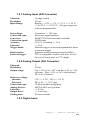
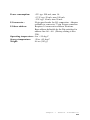
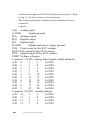
1
PCL-812PG
Enhanced Multi-Lab Card
User's Manual for PCL-812PG
Copyright Notice
This documentation and the software routines contained in the
PCL-812PG software diskette are copyrighted, 1993, by Advantech Co. Ltd. All rights are reserved. Advantec reserves the right
to make improvements to the products described in this manual at
any time without notice.
No part of this manual may be reproduced, copied, translated or
transmitted in any form or by any means without the prior written
permission of the original manufacturer. Information provided in
this manual is intended to be accurate and reliable. However, the
original manufacturer assumes no responsibility for its use, nor
for any infringements upon the rights of third parties which may
result from its use.
Acknowledgements
PC-LabCard is a trademark of Advantech Co., Ltd.
IBM and PC are trademarks of International Business Machines
Corporation.
MS-DOS is a trade mark of Microsoft Corporation.
BASIC is a trademark of Dartmouth College. Intel is a trademark
of Intel Corporation.
Part No. XXX Rev. B1
Printed in Taiwan November 1996
Packing List
Before installing your board, insure that the following materials
have been received:
•
If any of these items are missing or damaged, contact your
distributor or sales representative immediately.
CHAPTER
1
General Information
This chapter gives background
information on the PCL-812PG.
Sections include:
• Key Features
• Expansion Capabilities
• Product Specifications
Chapter 1
General Information
9
1.1 Introduction
The PCL-812PG is a high performance, high speed, multi-function
data acquisition card for IBM PC/XT/AT and compatible
computers. The high-end specifications fo this full-sized card, and
complete software support from third-party vendors makes it ideal
for a wide range of applications in industrial and laboratory
environments. These applications include data acquisition, process
control, automatic testing and factory automation.
1.2 Key Features
• 16 single-ended analog input channels
• An industrial standard 12-bit successive approximation converter
(HADC574Z) to convert analog inputs. The maximum A/D
sampling rate is 30 KHz in DMA mode.
• Software programmable analog input ranges.
• Bipolar: +/- 5V, +/- 2.5 V, +/- 1.25V +/- 0.625 V +/- 0.3125 V
• Three A/D trigger modes:
• Software trigger
• Programmable pacer trigger
• External pulse trigger
• The ability to transfer A/D converted data by program control,
interrupt handler routine or DMA transfer.
• An Intel 8253-5 Programmable Timer/Counter provides pacer
output (trigger pulse) at the rate of 0.5 MHz to 35 minutes/pulse.
The timer increment is 2 MHz. One 16-bit counter channel is
reserved for user configuration applications.
• Two 12-bit monolithic multiplying D/A output channels. An
output range from 0 to +5V or 0 to +10V can be created by using
the on-board -5V or -10V reference. This precision reference is
derived from the A/D converter reference. External AC or DC
references can also be used to generate other D/A output ranges.
10
PCL-812PG
User's Manual
• 16 TTL/DTL compatible digital inputs, and 16 digital output
channels.
1.3 Expansion Capabilities
To complement the powerful features of the PCL-812PG, the
versatility of the card can be enhanced by using the following
optional daughter boards:
PCLD-789 Amplifier/Multiplier Board
This powerful front end analog input signal conditioning card can
multiplex 16 differential inputs to one A/D input channel. A high
grade instrumentation amplifier provides switch selectible gains of
0.5, 1, 2, 10, 50, 100, 200, 1000 or any user-definable gain.
PCLD-787 Eight Channel Simultaneous Sample and Hold
Front-End Board
The board allows up to eight analog inputs to be acquired
simultaneously with less than 30 ns of channel-to-channel sample
time uncertainty.
PCLD-786 AC/DC Power SSR and Relay Driver Board
This board provides 8 channels of photo-couple isolated solid-state
relay modules, plus an additonal 8 external relay driver outputs.
PCLD-785/885 Relay Output Board
This board provides 16 SPDT relays driven by the 16-bit digital
output channels of the PCL-812PG.
PCLD-782 Isolated D/I Board
This 16-channel opto-isolated digital input board provides an easy
way to input digital signals to the PCL-812PG.
PCLD-780 Wiring Terminal
Wiring terminal board for easy analog and/or digital I/O
connections
PCLD-779 Eight Channel Isolated Multiplexer and
Amplifier Board
Offers multi-channel temperature measurements when connected
Chapter 1
General Information
11
with a PC-LabCard.
PCLD-770/7701/7702 Signal Conditioning Modules
PCLD-770 Signal Conditioning Module Carrier Board.
With the PCLD-770 board, you can configure your requirements
with a signal conditioning module such as the PCLD-7701 or
PCLD-7702.
PCLD-7701 Isolated Amplifier
PCLD-7702 Amplifier with I/V Source
PCLD-5B16 Module Carrier Board
This module carrier board is equipped with 16 channels of 5B
series input and/or output modules which provide a complete
solution for signal conditioning applications.
1.4 Software Support
The PCL-812PG also provides powerful and easy to use software
driver functions which can be accessed by referring a user-defined
parameter table. These driver functions simplify programming,
especially when you want to use some of the sophisticated features
available with the PCL-812PG, for example, interrupt or DMA
data transfer.
To provide PCL-812PG users with more application support, a
variety of excellent third-party application software packages have
been integrated with the PCL-812PG. At present, the PCL-812PG
is supported by the following software:
PC-LabsDAS
Turnkey, menu-driven, general purpose data acquisition package
from Advantech
Labtech Notebook, PC-Scope, PC-Streamer, SNAPSHOT,
etc.
A complete software product catalog is available free from your
local PC-LabCard representative.
1.5 Product Specifications
12
PCL-812PG
User's Manual
1.5.1 Analog Input (A/D Converter)
Channels:
Resolution:
Input Range:
16 single-ended
12 bits
Bipolar +/- 10V, +/- 5V, +/- 2.5 V, +/- 1.25 V,
+/- 0.625 V, +/- 0.3125 V. All input ranges are
software programmable.
Overvoltage:
Conversion type:
Converter:
Conversion speed:
Accuracy:
Linearity:
Trigger mode:
Continuous +/- 30V max.
Successive approximation
HADC574Z (built-in sample and hold)
30 KHz max.
0.015 % of reading +/- 1 bit
+/- 1 bit
Software trigger, on-board programmable timer
or external trigger.
Program control, Interrupt control or DMA
TTL or compatible, load 0.4 mA max. at 0.5V
(low) or 0.05 mA max. at 2.7V (high).
Data transfer:
External trigger
1.5.2 Analog Output (D/A Converter)
Channels:
Resolution:
Output range:
Reference voltage
Internal:
External:
Conversion type:
Analog devices:
Linearity:
Output drive:
Settling time:
2
12 bits
0 to + 5V or 0 to +10V with fixed -5V or -10V
reference. Max. +10V or -10V with external
DC or AC reference.
-5V (+/- 0.1V), -10V (+/- 0.2 V)
DC or AC, +/- 10 V max
12-bit monolithic multiplying
AD7541AKN or equivalent
+/- 0.5 bit
+/- 5 mA max
30 microseconds
1.5.3 Digital Input
Chapter 1
General Information
13
Channel:
Level:
Input voltage
Low:
High:
Input load
Low:
High:
16 bits
TTL compatible
0.8 V max
2.0V min.
0.4 mA max. at 0.5 V
0.05 mA max. at 2.7 V
1.5.4 Digital Output
Channel:
Level:
Output voltage
Low:
High:
16 bits
TTL compatible
Sink 8 mA at 0.5 V max.
Source -0.4 mA at 2.4V min.
1.5.5 Programmable Timer/Counter
Device:
Counters:
Input, gate:
Time base:
Pacer output:
Intel 8253
3 channels, 16-bit, 2 channels permanently
connected to 2 MHz clock as programmable
pacer, 1 channel free for user application
TTL/DTL/CMOS compatible
2 MHz
35 minutes/pulse to 0.5 MHz
1.5.6 Interrupt Channel
Level:
IRQ 2 to 7, 10, 11, 12, 14, 15 jumper
selectable
VIA S0, S1 and S2 of CONTROL register
Enable:
1.5.7 DMA Channel
Level:
Enable:
1 or 3, jumper selectable
Via S0, S1 and S2 of CONTROL register
1.5.8 General Specifications
14
PCL-812PG
User's Manual
Power consumption:
+5V: typ. 500 mA, max 1A
+12 V: typ. 50 mA, max 100 mA
-12V: typ. 14 mA, max 20 mA
I/O connector:
20 pin post header for I/O connection. Adapter
available to convert to 37 pin D-type connector
I/O base address:
Requires 16 consecutive address locations.
Base address definable by the Dip switches for
address line A8 - A4. (Factory setting is Hex
220).
Operating temperature: 0 to + 50 deg C
Storage temperature:
-20 to +65 deg C
Weight:
8.6 oz (243 g)
Chapter 1
General Information
15
2.1 Initial Inspection
Inside the shipping container, you should find this operating
manual and the PCL-812PG card. The PCL-812PG is carefully
inspected and tested (mechanically and physically) prior to
shipping. It should be free of marks and scratches and in perfect
working order upon delivery.
When unpacking, check the unit for signs of shipping damage
(damaged box, scratches, dents, etc.). If there is any damage to
the unit or it fails to meet specifications, notify our service
departmet or your local sales representative immediately. In
addition, report the damage to the carrier. Retain the shipping
carton and packing material for inspection by the carrier. We
will then make arrangements to repair or replace the unit.
Remove the PCL-812PG interface card from its protective
packaging by grasping the rear metal panel. Keep the antivibration packing. Whenever you remove the card from the PC
expansion slot, store the card in the protective package.
Discharge any static electricity by touching the back of the
system unit before you handle the board. You should avoid
contact with materials that create static electricity such as plastic,
vinyl and styrofoam. The board should be handled on by its
edges to avoid static electricity discharge which could damage
the integrated circuits on the PCL-812PG.
2.2 Jumper Settings
The PCL-812PG is designed for ease of use. There is one DIP
switch and nine jumpers on the PCL-812PG card and the
functions of the switch and the jumpers are discussed in this
section. You may want to refer to Fig. 2.1 for the physical
location 5 of the switch and the jumpers.
18
PCL-812PG User's Manual
2.2.1 Base Address Selection
Switch name: SW1
Most PC peripheral devices and interface cards are controlled
through the input/output (I/O) ports. These ports are addressed
using the I/O port address space. Appendix A provides a PC I/O
port address map to help you locate appropriate addresses for
different devices.
The I/O port base address for the PCL-812PG is selectable via an
8-position DIP switch. The PCL-812PG requires 16 consecutive
address locations in I/O space. Valid addresses are from hex 200
to hex 3F0; however, you might have used some of these
addresses for other devices. Your PCL-812PG base address
switch setting is set to hex 220 in the factory. If you need to
adjust it to some other address range, the switch settings for
various base addresses are illustrated as below:
Note:
ON = 0, OFF = 1
A4...A9 correspond to PC bus address lines
* denotes factory setting
2.2.2 Wait State Selection
Some high speed PCs may require wait states to be added to the
bus I/O to achieve stable data transfer. The PCL-812PG can be
configured with 0, 2, 4 or 6 wait state delay for each transfer of
data. The length of the wait state can be selected with the
positions 7 and 8 on SW1, as shown below:
2.2.3 DMA Channel Selection
Jumper name: JP6, JP7
The PCL-812PG provides DMA data transfer capability. The
selection of DMA level 1 or level 3 is controlled by the jumpers.
No DMA:
Chapter 2 General Information
19
connectors through our PCLK-1050 industrial wiring kit. Refer
to Fig. 2.1 for the location of each connector.
The following diagrams illustrate the pin alignment of each
connector.
Legend:
A/D Analog input
A.GND
Analog ground
D/A Analog output
D/O Digital output
D/I
Digital input
D.GND
Digital and power supply ground
CLK Clock input for the 8253 counter
GATE Gate input for the 8253 counter
OUT Signal output of the 8253 counter
VREF Voltage reference
Connector 1 (CN1) Analog Input (single-ended channels)
A/D 0
1
2
A.GND
A/D 1
2
4
A.GND
A/D 2
5
6
A.GND
A/D 3
7
8
A.GND
A/D 4
9
10
A.GND
A/D 5
11
12
A.GND
A/D 6
13
14
A.GND
A/D 7
15
16
A.GND
A/D 8
17
18
A.GND
A/D 9
19
20
A.GND
Connector 2 (CN2) - Analog Output
A/D 10
1
2
A.GND
A/D 11
3
4
A.GND
A/D 12
5
6
A.GND
A/D 13
7
8
A.GND
22
PCL-812PG User's Manual
A/D 14
9
10
A.GND
A/D 15
11
12
A.GND
D/A 1
13
14
A.GND
D/A 2
15
16
A.GND
V.REF 1
17
18
A.GND
V.REF 2
19
20
A.GND
Connector 3 (CN3) Digital Output
D/0
0
1
2
D/0
1
D/0
2
3
4
D/0
3
D/0
4
5
6
D/0
5
D/0
6
7
8
D/0
7
D/0
8
9
10
D/0
9
D/0
10
11
12
D/0
11
D/0
12
13
14
D/0
13
D/0
14
15
16
D/0
15
D.GND
17
18
D.GND
+ 5V
19
20
+ 12V
Connector 4 (CN4) - Digital Input
D/I
0
1
2
D/I
1
D/I
2
3
4
D/I
3
D/I
4
5
6
D/I
5
D/I
6
7
8
D/I
7
D/I
8
9
10
D/I
9
D/I
10
11
12
D/I
11
D/I
12
13
14
D/I
13
D/0
14
15
16
D/I
15
D.GND
17
18
D.GND
+ 5V
19
20
+ 12V
Connector 5 (CN5) - Counter
EX.TRG
1
2
EX.TRG
3
4
EX.TRG
5
6
CTR1 GATE
Chapter 2 General Information
23
EX.TRG
7
8
CTR0 CLK
EX.TRG
9
10
CTR0 OUT
EX.TRG
11
12
CTR0 GATE
EX.TRG
13
14
CTR1 OUT
EX.TRG
15
16
EX.TRG
17
18
D.GND
EX.TRG
19
20
2.4 Hardware Installation
Warning:
Turn off your PC power supply whenever
installing or removing the PCL-812PG or connecting and
disconnecting cables.
Installing the card in your computer:
Turn the computer off. Disconnect the power to any
peripheral devices (printer, monitor, etc.)
Disconnect the power cord and any other cables from the
back of the computer. Turn the system unit so the back of
the unit is facing you.
Remove the system unit cover (refer to your computer's
user's manual, if necessary)
Locate the expansion slots at the rear of the unit and choose
any unused slot.
Remove the screw that secures the expansion slot cover to the
system unit (save the screw to secure the interface card
retaining bracket).
Carefully grasp the upper edge of the PCL-812PG card.
Align the hole in the retaining bracket with the hole on top of
the expansion slot, and align the gold-striped edge connector
with the expansion slot socket. Press the board firmly into
the socket.
Replace the screw in the expansion slot retaing bracket.
Attach the necessary accessories (e.g. 20-pin flat cable or
connector adapter, etc.) to the interface card based on your
24
PCL-812PG User's Manual
CHAPTER
Installation
2
This chapter provides detailed
installation information about
the PCL-812PG.
Sections include:
• Initial inspection
• Jumper settings
• Connector pin assignments
• Hardware installation
• Software installation
Chapter 2 General Information
17
2.1 Initial Inspection
Inside the shipping container, you should find this operating
manual and the PCL-812PG card. The PCL-812PG is carefully
inspected and tested (mechanically and physically) prior to
shipping. It should be free of marks and scratches and in perfect
working order upon delivery.
When unpacking, check the unit for signs of shipping damage
(damaged box, scratches, dents, etc.). If there is any damage to
the unit or it fails to meet specifications, notify our service
departmet or your local sales representative immediately. In
addition, report the damage to the carrier. Retain the shipping
carton and packing material for inspection by the carrier. We
will then make arrangements to repair or replace the unit.
Remove the PCL-812PG interface card from its protective
packaging by grasping the rear metal panel. Keep the antivibration packing. Whenever you remove the card from the PC
expansion slot, store the card in the protective package.
Discharge any static electricity by touching the back of the
system unit before you handle the board. You should avoid
contact with materials that create static electricity such as plastic,
vinyl and styrofoam. The board should be handled on by its
edges to avoid static electricity discharge which could damage
the integrated circuits on the PCL-812PG.
2.2 Jumper Settings
The PCL-812PG is designed for ease of use. There is one DIP
switch and nine jumpers on the PCL-812PG card and the
functions of the switch and the jumpers are discussed in this
section. You may want to refer to Fig. 2.1 for the physical
location 5 of the switch and the jumpers.
18
PCL-812PG User's Manual
2.2.1 Base Address Selection
Switch name: SW1
Most PC peripheral devices and interface cards are controlled
through the input/output (I/O) ports. These ports are addressed
using the I/O port address space. Appendix A provides a PC I/O
port address map to help you locate appropriate addresses for
different devices.
The I/O port base address for the PCL-812PG is selectable via an
8-position DIP switch. The PCL-812PG requires 16 consecutive
address locations in I/O space. Valid addresses are from hex 200
to hex 3F0; however, you might have used some of these
addresses for other devices. Your PCL-812PG base address
switch setting is set to hex 220 in the factory. If you need to
adjust it to some other address range, the switch settings for
various base addresses are illustrated as below:
Note:
ON = 0, OFF = 1
A4...A9 correspond to PC bus address lines
* denotes factory setting
2.2.2 Wait State Selection
Some high speed PCs may require wait states to be added to the
bus I/O to achieve stable data transfer. The PCL-812PG can be
configured with 0, 2, 4 or 6 wait state delay for each transfer of
data. The length of the wait state can be selected with the
positions 7 and 8 on SW1, as shown below:
2.2.3 DMA Channel Selection
Jumper name: JP6, JP7
The PCL-812PG provides DMA data transfer capability. The
selection of DMA level 1 or level 3 is controlled by the jumpers.
No DMA:
Chapter 2 General Information
19
DMA 1:
DMA 3:
2.2.4 Trigger Source Selection
Jumper Name: JP1
The A/D conversion trigger source can be internal on-board
programmable pacer or external pulse signal (connector CN5 pin
1)
Internal pacer trigger:
2.2.5 User's Counter Input Clock Selection (JP2)
The programmable timer/counter has 3 channel 16 bit counters.
Channel 1 and channel 2 are configured as internal pacer and
channel 0 is left for user's applications. The clock input of
channel 0 can be internal 2 MHz clock or external clock signal
from connector CN5 pin 8.
Internal 2 MHz clock:
External clock:
2.2.6 IRQ Level Selection (JP5)
The interrupt caused by A/D conversion completion can be level
2 to 7, 10, 11, 12, 14, 15. It is selected by JP5. The user must be
aware there is no other add-on card sharing the same interrupt
level.
No interrupt:
IRQ level 2:
2.2.7 D/A Reference Source Selection (JP3, JP4)
The reference voltage of D/A converters can be the internally
generated -5 or -10 V or an external reference voltage from
connector CN2 pin 17 or pin 19. The reference source of D/A
channel 1 (2) is selected by JP3 (4).
20
PCL-812PG User's Manual
The reference voltages of both D/A CH1 and CH2 are external:
The reference of D/A CH1 is internal and that of CH2 is external:
2.2.8 D/A Internal Reference Selection (JP8)
The internal reference voltage can be -5V or -10V. It is selected
by JP8. The reference voltage is -10V and the D/A output range
is 0 to +10V:
The reference voltage is -5V and the D/A output range is 0 to
+5V:
The internal reference is used only when the jumper JP3 or JP4 is
set to INT.
2.2.9 A/D Maximum Input Voltage Selection (JP9)
The A/D converter range can be +/- 5V or +/- 10V at it is
selected by jumper JP9. If JP9 is set in the +/- 5V range, the
analog input ranges of PCL-812PG are +/- 5V, +/- 2.5 V, +/1.25V, +/- 0.625V and +/- 0.3125V. If JP9 is set to the +/- 10V
range, the analog input ranges are then +/- 10V, +/- 5V, +/- 2.5V,
+/- 1.25V and +/- 0.625V. The default setting of JP9 is the +/5V range. The user can set JP9 to +/- 10V to double the input
range.
Some PC power supplies offer the bias voltage Vcc + with a
voltage less than +12V, e.g. +11.2V. In this case, the output
voltage swing range of the programmable amplifier cannot reach
+10V and the A/D converter CANNOT make correct
measurement if JP9 is set to +/- 10V range.
A/D converter maximum input range is +/- 10V:
2.3 Connector Pin Assignment
The PCL-812PG is equipped with two 20-pin insulation
displacement (mass termination) connectors, accessible from the
rear plate, and three other 20-pin insulation displacement
connectors on-board. All these connectors can be connected to
the same type of flat cables, or connected to 37-pin D-type
Chapter 2 General Information
21
connectors through our PCLK-1050 industrial wiring kit. Refer
to Fig. 2.1 for the location of each connector.
The following diagrams illustrate the pin alignment of each
connector.
Legend:
A/D Analog input
A.GND
Analog ground
D/A Analog output
D/O Digital output
D/I
Digital input
D.GND
Digital and power supply ground
CLK Clock input for the 8253 counter
GATE Gate input for the 8253 counter
OUT Signal output of the 8253 counter
VREF Voltage reference
Connector 1 (CN1) Analog Input (single-ended channels)
A/D 0
1
2
A.GND
A/D 1
2
4
A.GND
A/D 2
5
6
A.GND
A/D 3
7
8
A.GND
A/D 4
9
10
A.GND
A/D 5
11
12
A.GND
A/D 6
13
14
A.GND
A/D 7
15
16
A.GND
A/D 8
17
18
A.GND
A/D 9
19
20
A.GND
Connector 2 (CN2) - Analog Output
A/D 10
1
2
A.GND
A/D 11
3
4
A.GND
A/D 12
5
6
A.GND
A/D 13
7
8
A.GND
22
PCL-812PG User's Manual
A/D 14
9
10
A.GND
A/D 15
11
12
A.GND
D/A 1
13
14
A.GND
D/A 2
15
16
A.GND
V.REF 1
17
18
A.GND
V.REF 2
19
20
A.GND
Connector 3 (CN3) Digital Output
D/0
0
1
2
D/0
1
D/0
2
3
4
D/0
3
D/0
4
5
6
D/0
5
D/0
6
7
8
D/0
7
D/0
8
9
10
D/0
9
D/0
10
11
12
D/0
11
D/0
12
13
14
D/0
13
D/0
14
15
16
D/0
15
D.GND
17
18
D.GND
+ 5V
19
20
+ 12V
Connector 4 (CN4) - Digital Input
D/I
0
1
2
D/I
1
D/I
2
3
4
D/I
3
D/I
4
5
6
D/I
5
D/I
6
7
8
D/I
7
D/I
8
9
10
D/I
9
D/I
10
11
12
D/I
11
D/I
12
13
14
D/I
13
D/0
14
15
16
D/I
15
D.GND
17
18
D.GND
+ 5V
19
20
+ 12V
Connector 5 (CN5) - Counter
EX.TRG
1
2
EX.TRG
3
4
EX.TRG
5
6
CTR1 GATE
Chapter 2 General Information
23
EX.TRG
7
8
CTR0 CLK
EX.TRG
9
10
CTR0 OUT
EX.TRG
11
12
CTR0 GATE
EX.TRG
13
14
CTR1 OUT
EX.TRG
15
16
EX.TRG
17
18
D.GND
EX.TRG
19
20
2.4 Hardware Installation
Warning:
Turn off your PC power supply whenever
installing or removing the PCL-812PG or connecting and
disconnecting cables.
Installing the card in your computer:
Turn the computer off. Disconnect the power to any
peripheral devices (printer, monitor, etc.)
Disconnect the power cord and any other cables from the
back of the computer. Turn the system unit so the back of
the unit is facing you.
Remove the system unit cover (refer to your computer's
user's manual, if necessary)
Locate the expansion slots at the rear of the unit and choose
any unused slot.
Remove the screw that secures the expansion slot cover to the
system unit (save the screw to secure the interface card
retaining bracket).
Carefully grasp the upper edge of the PCL-812PG card.
Align the hole in the retaining bracket with the hole on top of
the expansion slot, and align the gold-striped edge connector
with the expansion slot socket. Press the board firmly into
the socket.
Replace the screw in the expansion slot retaing bracket.
Attach the necessary accessories (e.g. 20-pin flat cable or
connector adapter, etc.) to the interface card based on your
24
PCL-812PG User's Manual
application requirements.
Replace the system unit cover. Connect the cables you
removed in step 2. Turn the computer's power on.
The hardware installation is now complete. Proceed to install
the software driver.
2.5 Software Disk
A floppy diskette containing utility software is included with
each PCL-812PG to minimize your application programming
work and support the PCL-812PG calibration. The utility
programs include:
A comprehensive I/O driver for A/D, D/A, digital I/O and
counter applications. This driver allows you to use standard
functions, written in common programming languages, to
operate the PCL-812PG, without going into detailed register
control. Languages supported by the software driver include
BASICA, GWBASIC, QUICKBASIC, Microsoft C/C++ and
PASCAL, Turbo C/C++, Borland C/C++ and Turbo
PASCAL. Refer to the Software Driver's User's Manual for
more information.
Demonstration programs
Calibration program
Test program
It is strongly recommended that you make a working copy
from the master diskette and save the master in a safe place.
You can use the DOS COPY or DISKCOPY commands to
copy the diskette files to another floppy disk or use the
COPY command to copy the files to a hard disk drive. Refer
to your MS-DOS user's manual for details of how to make
backup copies of your diskette.
Chapter 2 General Information
25
Signal Connection
Correct signal connection is one of the most important important steps to assure your application
system will send and receive data correctly. Since most data acquisition applications involve
voltage, correct signal connection prevents costly damage to your personal computer and
hardware devices. This chapter provides some useful information on signal connection in
different types of data acquisition applications.
3.1 Analog Input Connection
The PCL-812PG supports a 16 single-ended analog input configuration. The single-ended
configuration has only one signal wire for each channel. The voltage to be measured is the
voltage of this wire referred to the common ground. A signal source without a local ground is
also called a "floating source". It is fairly simple to connect a single ended channel to a floating
signal source. A standard wiring diagram is illustrated below:
3.2 Expanding Analog Inputs
You may expand any or all of the PCL-812PG A/D input channels through sub-multiplexers.
The PCLD-789 Amplifier and Multiplexer daughter board in the PC-LabCard series is
specifically designed for multiplexing applications. Each PCLD-789 can multiplex 16
differential inputs to one A/D input channel. Up to eight PCLD-789s can be cascaded to one
PCL-812PG providing a total of 128 channels. Complete operation information of using the
PCL-812PG with the PCLD-789 is covered in the PCLD-789 user's manual.
The PCLD-774 analog expansion board is designed to accommodate multiple external signalconditioning daughterboards, such as the PCLD-779, PCLD-789, PCLD-889. Featuring five sets
of on-board 20-pin header connectors, the PCLD-774 introduces a new star-type architecture that
allows cascading of multiple signal-conditioning daughterboards. The signal-attenuation and
current-loading problems of normal cascading are solved by this unique arrangement. For
information about these products, please contact your local PC-LabCard sales representative.
3.3 Analog Output Connection
PCL-812PG provides two D/A output channels. You may use the PCL-812PG's internallly
generated precision -5V and -10V reference to generate 0 to +5V and 0 to +10V D/A output
range. You may create other D/A output ranges through external references. The maximum
reference input range is +/- 10V and maximum output scaling is +/- 10V. The PCL-812PG
conector CN2 is used for D/A signals. Some important areas in D/A signal connections are input
reference, D/A outputs and analog ground. The PCL-812PG D/As should be be connected as
illustrated below:
Legend (Connector 2 pin number):
13 = D/A 1 D/A outputs
15 = D/A 2 D/A outputs
14 = Analog ground
16 = Analog ground
17 = V.REF1
19 = V.REF2
3.4 Digital Signal Connection
The PCL-812PG has 16 digital input and 16 digital output channels. The digital I/O levels are
TTL compatible. To transmit or receive digital signal to/from other TTL devices, the connection
is:
To receive an OPEN/SHORT signal from a switch or relay, a pull-up resistor must be added to
ensure he high level when open.
Register Structure and Format
The PCL-812PG requires 16 consecutive addresses in I/O space. The most important issue in
programming the PCL-812PG is understanding the meaning of the 16 registers addressable from
the selected I/O port base address. A summary map of the functions of each address and the data
format of each register are given in the following sections.
4.1 I/O Port Address Map
The following table shows the location of each register and driver relative to the base address,
and its usage.
4.2 A/D Data Registers
The A/D data registers use address BASE +4 and +5
Data Format:
A/D Low Byte and Data
A/D High Byte
Legend:
AD11 to AD0 Analog to digital data. AD0 is the least significant byte (LSB) and AD11 is the
most significant byte (MSB) of the A/D data.
DRDY
Data ready signal. When the A/D data is not ready, this bit is 1. DRDY
becomes 0 when A/D conversion completed and it is set to 1 when reading A/D low byte register
BASE +4.
4.3 MUX Control Register
The multiplexer control register is a write-only register using address BASE +10. The low
nybble provides the scan channel number. The multiplexer switches to the new channel when
writing to this register.
Data Format:
Legend:
CL3 to CL0 - Multiplexer channel number
4.4 Digital I/O Registers
The PCL-812PG offers 16 digital input channels and 16 digital output channels. These I/O
channels used the input address BASE +6 and BASE +7. The output ports are at BASE +13 and
BASE +14. The data format of each port is as follows:
Data Format:
4.5 D/A Output Registers
The D/A output registers are write registers using address BASE +4, +5, +6 and +7.
Data Format:
Legend:
DA11 to DA0 Digital to analog data. DA0 is the least significant bit (LSB) and DA11 is the
most significant bit (MSB) of the D/A data. The register of the D/A low byte BASE +4 (BASE
+6) is double buffered. The data is stored in a buffer when writing BASE +4 (BASE +6).
When writing BASE +5 (BASE +7), the data in BASE +4 (BASE +6) is sent to D/A converter
with high byte data at the same time.
4.6 Gain Control Register
The gain control register is a write-only register using address BASE +9. It is used to set the
gain of the analog input programmable amplifier. The data format of this register and gain is
defined as below:
Data Format:
Gain Definition:
R2
R1
R0
GAIN
0
0
0
1
0
0
1
2
0
1
0
4
0
1
1
8
1
0
0
16
1
0
1
Invalid
1
1
0
Invalid
1
1
1
Invalid
The analog input range, maximum input voltage and gain has the relation as the following
equation:
Analog input range = maximum input voltage/gain
The maximum input voltage is selected by JP9. It can be +/- 5V or +/- 10V. The default
maximum input voltage is +/- 5V. From this equation, the analog input ranges are +/- 5 V, +/2.5V, +/-1.25 V, +/-0.625V, and +/- 0.3125V.
4.7 Mode Control Register
The mode control register is a write-only register using address BASE +11. This register
provides the way to control the operating modes of the PCL-812PG.
Data Format:
A. Under internal trigger condition (JP1 is set to internal)
B: Under external trigger source condition (JP1 is set to external)
*Note: Set up trigger jumper JP1 on EXT as below before using external trigger mode:
4.8 Programmable Interval Timer/Counter Registers
The four registers located at address BASE 0, 1, 2 and 3 are used for Intel 8253 programmable
timer/counter. Please refer to Chapter 8 or the 8253 product literature for detailed application
information.
A/D Conversion
This chapter provides a complete explanation of how to use the PCL-812PG A/D conversion functions. It covers A/D data format, input range selection, MUX multiplier channel control, trigger
modes and data transfer in the first sections. The last section give step-by-step implementation
guidelines on A/D operations.
5.1 A/D Data Format and Status Register
When the PCL-812PG performs 12-bit A/D conversions, an 8-bit register is not big enough to
accommodate all 12 bits of data. Therefore A/D data are stored in two registers located at address
BASE +4 and BASE +5. The A/D low byte data are in the positions D0 (AD0) through D7 (AD7)
of BASE +4 and high byte data are in the positions D0 (AD8) through D3 (AD11) of BASE +5.
The least significant bit is AD0 and the most significant bit is AD11. The A/D channel number
from which the conversion data derived is available at register BASE +10 postion D0 (CL0) to D3
(CL3). The gain is set at register BASE +9 position D0 (R0) to D2 (R2).
The data format of the A/D data registers is:
A/D Low byte and Channel number.
A/D High byte
5.2 MUX Setting
Data Format:
5.3 Gain Setting
Data Format:
5.4 Trigger Mode
The PCL-812PG A/D conversions can be triggered in any one of three ways - software trigger, onboard programmable pacer or external pulse trigger.
The software trigger is controlled by the application program issued software command. Writing to
register BASE +12 with any value causes a software trigger. This trigger mode is normally not used
in high-speed A/D applications due to the limitations of the applications program execution time.
The PCL-812PG uses the Intel 8253 programmable interval timer/counter. Counters 1 and 2 of the
Intel 8253 are configured to be a pacer to offer A/D converter trigger pulses with precise periods in
the pacer trigger mode. The pacer output of the PCL-812PG is between 0.5 MHz and 35 minutes/
pulse. Chapter 8 covers the details of using the Intel 8253 timer/counter. The pacer trigger mode is
ideal for interrupt and DMA data transfer which normally are used in A/D applications requiring a
higher conversion speed.
The PCL-812PG direct external trigger pulses are controlled through EXT.TRG (connector CN5 pin
1). This type of trigger mode is mostly used in A/D applidcations requiring A/D conversions not
periodically but conditionally, e.g. thermocouple temperature control.
5.5 A/D Data Transfer
There are three possbile ways to perform the PCL-812PG A/D data transfer - program control,
interrupt routine or DMA.
The program control data transfer uses the polling concept. After the A/D converter has been
triggered, the application program checks the data ready (DRDY) bit of the A/D high byte register.
If the DRDY bit is 0, the converted data is moved from the A/D data register to computer memory
by application program control.
In interrupt routine transfer, data is transferred from the A/D data registers to a previously defined
memory segment by the interrupt routine handler. At the end of each conversion, the data ready
signal generates an interrupt which enables the interrrupt handler routine to perform the transfer.
The interrrupt level selection on JP5, interrupt vector, interrupt controller 8259 and interrupt control
bit in the PCL-812PG control register (BASE +11) must be specified before the use of an interrupt
routine. A write action to the A/D status register address (BASE +8) with any value resets the PCL812PG interrupt request and re-enables the PCL-812PG interrupt.
Direct memory access (DMA) transfer moves the A/D data from the PCL-812PG hardware device
to the PC system memory without using the system's CPU. DMA is very useful in high speed data
transfer, but it is complicated to operate. The DMA level selection jumper, JP5 and JP6, and the
DMA enable bit in the PCL-812PG control register as well as the 8237 DMA controller registers
must be set up before performing DMA operations. It is recommended that users use the PCL812PG driver to perform DMA operations. For more information regarding the 8237 DMA controller and trhe PCL-812PG DMA operations, please read Chapter 9.
5.6 How to Execute an A/D Conversion
You may execute A/D operations with a program writing all I/O port instructions directly, or by a
program utilizing the PCL-812PG driver. It is suggested that you invoke the driver functions in
your program. This will make your programming job easier and enhance the program performance.
See Software Driver's User's Manual for more information.
To perform pacer trigger and program control data transfer without the PCL-812PG driver.
Set the inpt channel by writing the channel number to the multiplexer control register BASE +10.
Set the analog input range by writing the gain control register BASE +9.
Set the pacer trigger mode by writing the mode control register.
Wait for data ready by checking the A/D high byte register (BASE +5) DRDY bit.
Read data from A/D converter by reading the A/D data registers (BASE +5 and BASE +4). You
must first read the high byte.
Data conversion by converting the binary A/D data to an integer.