1
sat-nms LSM
L-Band Switch Matrix
User Manual
Version 1.3 / 2010-02-24
© Copyright
SatService Gesellschaft für Kommunikatiosnsysteme mbH
Hardstrasse 9
D-78256 Steisslingen
www.satnms.com
www.satservciegmbh.de
Tel +49 7738 97003
Fax +49 7738 97005
SatService
Gesellschaft für Kommunikationssysteme mbH
Table Of Contents
Table Of Contents ................................................................................................................................. 1
1 Introduction ........................................................................................................................................ 3
2 Installation ......................................................................................................................................... 3
2.1 Safety Instructions ........................................................................................................................ 4
2.2 Setting the IP Address .................................................................................................................. 4
2.3 Connecting the L-Band Switch Matrix ........................................................................................... 5
2.3.1 Power connectors and Power supplies ..................................................................................... 5
2.3.2 D/C and data connectors ......................................................................................................... 5
2.3.3 RF connectors ........................................................................................................................ 6
2.4 Configuring the L-Band Switch Matrix .......................................................................................... 6
2.5 Mechanical installation ................................................................................................................. 7
3 Operation ........................................................................................................................................... 7
3.1 The Web-based User Interface ..................................................................................................... 8
3.2 Switch parameters ........................................................................................................................ 8
3.3 Graphic switch parameters ........................................................................................................... 8
3.4 General Setup .............................................................................................................................. 8
3.5 Frontpanel Operation .................................................................................................................... 9
3.5.1 Connection Display ................................................................................................................ 9
3.5.2 The Main Menu ..................................................................................................................... 9
3.5.3 Editing Numeric Parameters ................................................................................................. 11
3.5.4 Editing Multiple Choice Parameters ...................................................................................... 11
4 Remote Control ................................................................................................................................ 12
4.1 General command syntax ............................................................................................................ 12
4.2 The TCP/IP remote control interface ........................................................................................... 12
4.3 The RS232 remote control interface ............................................................................................ 12
4.4 SNMP Control ............................................................................................................................ 12
4.5 Parameter list ............................................................................................................................. 12
5 Theory of Operation ......................................................................................................................... 13
5.1 Distribution module .................................................................................................................... 14
5.2 RF Switch module ...................................................................................................................... 14
5.3 Controller Module ...................................................................................................................... 14
5.4 Mechanical Design ..................................................................................................................... 15
5.5 Outline Drawings and Model variants .......................................................................................... 15
6 Specifications ................................................................................................................................... 17
(C) 2013, SatService GmbH
www.satnms.com
LSM-UM-1301 Page 1/18
SatService
Gesellschaft für Kommunikationssysteme mbH
(C) 2013, SatService GmbH
www.satnms.com
LSM-UM-1301 Page 2/18
SatService
Gesellschaft für Kommunikationssysteme mbH
1 Introduction
This document is the user manual provided with the sat-nms LSM switch matrix. It contains all necessary
information how to install, setup, and operate the unit. The user manual is available as a printed document
and for on-line reading on the switch matrix itself as well.
A Switch Matrix fits in the multimedia ground terminal as a central unit which collects at its input the receive
signals from all the antennas with their Low Noise Block Converters (LNC) and distribute these signals
without any blocking at numerous outputs. The switch matrix allows the user to switch each input to each
output without any blocking effects. This gives the user of a switch matrix an unlimited routing and
configuration capability. He can configure its total receive system in numerous ways depending to its
requirements on demand. This is especially necessary for occasional use and for monitoring purposes.
The focus during the development was on excellent RF performance and operational stability. So everything
is hot-swap. The sat-nms LSM switch matrices are designed in a modular form and are easy to expand to
any size .
Key features
19" compact design in 3, 6 or 9 HU
High port to port isolation
Amplitude Flatness over the whole L-Band frequency range
Redundant power supplies
Front panel display and keyboard
TCP/IP and HTTP Web Browser interface
In Service expansion by card possible
In Service exchange of cards
Dual redundant power supplies
Coaxial and optical interfaces possible
The paragraphs below give a short overview to the contents of the documentation. A subset of this
documentation is stored on the device itself, the complete documentation is available on the sat-nms
documentation CD and at www.satnms.com.
Installation: The installation chapter guides through the installation and setup of the sat-nms LSM. It
describes the mechanical concept of the LSM chassis and the assignment of the connectors. Finally
you learn in this chapter how to set the LSM's IP address, which is a essential precondition to operate
the LSM by means of a web browser. This section is available in the printed version only.
Operation: The sat-nms LSM is operated using a standard web browser like the Internet-Explorer or
Mozilla Firefox. The user interface design is straight forward and clearly structured. Operating the
LSM is mostly self-explanatory. Nevertheless, the 'Operation' chapter outlines the map of web pages
which make up the LSM user interface and elaborately describes the meaning of each alterable
parameter.
Remote Control: T he sat-nms LSM provides a versatile remote control interface. A monitoring &
control software may fully operate the LSM either through a TCP/IP network connection or through
the RS232 interface of the LSM. This chapter describes the communication protocol used for remote
control and lists all parameters accessible through the remote interface.
Theory of Operation : This chapter gives a short overview how the matrix and the different modules
works together.
Specifications: At the end of the document, the specifications applicable to the sat-nms LSM are
summarized in this chapter.
Support and Assistance
If you need any assistance regarding our sat-nms LSM, don't hesitate to contact us. We would be pleased to
help you by answering your questions.
SatService GmbH phone +49 7738 9700-3 or -4
Hardstrasse 9
fax +49 7738 97005
78256 Steisslingen www.satnms.com
- Germany Version 1.3 / 2010-02-24
(C) 2013, SatService GmbH
www.satnms.com
LSM-UM-1301 Page 3/18
SatService
Gesellschaft für Kommunikationssysteme mbH
2 Installation
This chapter describes how to install the sat-nms LSM L-Band Switch Matrix. You find a guide how to
connect, configure and mechanically mount the Matrix below.
Before you start, please first read the Safety Instructions chapter below. It contains some important
recommendations to prevent damage from the equipment.
Then, we strongly recommend to do a first setup of the unit on a lab desk before installing it at it's final
location. This is mainly for the following reason:
1. To setup the L-Band Switch Matrix' IP parameters, the PC used for configuring and the L-Band
Switch Matrix must either be connected to the same Ethernet hub / switch or must be connected
directly with a crossover cable. The initialization program does not work through routers intelligent
network switches.
Hence, the typical sequence of tasks when putting an sat-nms LSM into operation is as follows:
1.
2.
3.
4.
5.
Read the chapter Safety Instructions
Set the unit's IP address
Connecting the switch matrix
Quick start Configuration
Mechanically installation of the unit
2.1 Safety Instructions
Failure to observe all Warnings and Cautions may result in personnel injury and/or equipment damage not
covered by the warranty.
Follow standard Electrostatic Discharge (ESD) procedures when handling a L-Band Switch Matrix
Unit.
Select and apply the appropriate 24V D/C voltage according to the data sheet and documentation
before connecting power.
Depending on configuration of the L-Band Switch Matrix is equipped with User-changeable power
supplies. Always disconnect the mains of the power supply that has to be changed. Wait at least 10s
after diconnecting the mains (for internal discharge of the power supply) before removing the power
supply ATTENTION: To avoid the possibility of an electrical shock, never handle with a power
supply that is connected to mains.
The power supplies are EMI filtered. The chassis is connected to earth ground in compliance with
safety requirements. Always use the 3-prong AC plug with earth ground to avoid possibility of
electrical shock hazard to personnel.
The L-Band Switch Matrix will be damaged if the total RF input power is higher than +10dBm
specified maximum value. Do not connect the RF input of the L-Band Switch Matrix to interfaces
where the total output power is higher than the specified value of the data sheet or indicated on the LBand Switch Matrix. .
The L-Band Switch Matrix will get warm during operation. To prevent an overheating leave at least
1HU below and above the L-Band switch matrix to allow the rejected heat to dissipate.
In case of a failure do not open the L-Band Switch Matrix, you will loose warranty, call SatService
GmbH for an RMA number.
Observe normal safety precautions when operating, servicing, and troubleshooting this equipment.
Take standard safety precautions with hand and/or power tools.
When connecting the L-Band Switch Matrix' fault relay circuits, observe the maximum ratings: 110V
D/C 300mA, 125V A/C 500mA.
2.2 Setting the IP Address
Before you can operate the sat-nms LSM L-Band Switch Matrix, you need to set the units's IP address.
There is a special configuration program on the documentation CD shipping with the unit for this purpose.
We recommend to configure Matrix' TCP/IP settings before you install L-Band Switch Matrix at it's final
place. To configure L-Band Switch Matrix, the following equipment is required:
The sat-nms LSM L-Band Switch Matrix itself
110…240V A/C power
A Computer running a Microsoft Windows operating system equipped with CD-ROM drive and
Ethernet network card.
A CAT5 crossover network cable or a Ethernet hub/switch and standard network cables to connect the
LSM and the computer.
The CD-ROM shipping with the sat-nms LSM.
Setting the L-Band Switch Matrix' IP parameters now is easily done within a few minutes.
1. First install a network cable between the L-Band Switch Matrix and your computer. If you have a
crossover cable available, this is very easy: simply put the cable into the network connectors of
computer and L-Band Switch Matrix. Without a crossover cable, you need to connect both, the
computer and L-Band Switch Matrix to the same network hub or switch using two standard network
cables. It is essential, that the computer and the L-Band Switch Matrix are connected to the same
network segment, the configuration program is not able to find the L-Band Switch Matrix through
routers or network switches.
2. Now power on your computer and connect L-Band Switch Matrix to the 110…240V A/C supply.
3. Insert the CD-ROM into the computer's drive and inspect it's contents through the 'My Computer' icon
on your desktop. Double-click to the 'ChipTool.exe' program in the 'ChipTool' directory.
4. When the ChipTool program is running, type CTRL+F to make the program search the LSM. The
program shows a list containing at least one entry describing the actual network parameters of the
LSM.
5. The serial number shown in the first column of the list, must match the serial number printed on the
processor's enclosure. If the list stays empty, the LSM is not connected properly. If there are more
entries in the list, the configuration program has found other devices in this network segment which
use the same technology.
6. Now type CTRL+I to open the IP configuration window of the program. In this form enter the
processor's serial number, it's new IP address and network mask. If the LSM later shall be operated
through a router, enter the address of the router on the gateway field, otherwise leave this field blanc.
Be sure, that the 'DHCP' mark is unchecked. Finally click to the 'Yes' button to set the new parameters
at the LSM.
Now the IP configuration of the L-Band Switch Matrix is completed. You may finally want to test if the L-
(C) 2013, SatService GmbH
www.satnms.com
LSM-UM-1301 Page 4/18
SatService
Gesellschaft für Kommunikationssysteme mbH
Band Switch Matrix is reachable now. Start your web browser and type the L-Band Switch Matrix' IP
address into the URL field of the browser. The L-Band Switch Matrix should reply with it's main page,
provided that the L-Band Switch Matrix and your computer are configured for the same subnet.
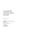
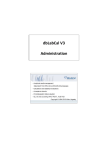
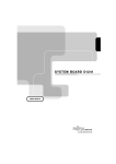
2.3 Connecting the L-Band Switch Matrix
The connectors of the L-Band Switch Matrix are placed on the rear side of the enclosure. Right hand you
can find the A/C Power and Data connectors, left hand the RF connectors. The following picture shows you
the location of the connectors at a 8x8 L-Band Switch Matrix.
When you connect the L-Band Switch Matrix, please consider the following:
J1.2 LAN is the Ethernet 10Base-T / RJ45 connector. Use a standard network cable to connect the LBand Switch Matrix to an Ethernet hub or switch. If you want to connect your computer and the unit
directly without using a hub, you need a crossover cable for this with swapped RX/TX lines.
J1.1 serial is a standard 9-pin RS232 (DCE) SUB-D pin-connector. You may use a direct 9-pin cable
to connect a PC to the L-Band Switch Matrix. The RTS/CTS and the DTR/DSR lines are bridged in
the unit to simulate hardware handshaking. They need however not to be connected, if you want to
use a 3 wire cable.
J1.3 Alarm is a standard 9-pin SUB-D socket-connector. This connector contains the alarm contacts
of the internal failure relais.
J1 and J2 are the power-inputs. Use only IEC plugs to connect the power supplies. Don´t forget to
connect the GND-labelled screw to the ground potencial.
The input and output RF-connectors are all SMA/50Ohm female.
2.3.1 Power connectors and Power supplies
Power connectors
At first, connect the screw, labeled with "GND" to Ground (e.g. to the 19"-Rack the L-Band Switch Matrix
is mounted in). After that connect the L-Band Switch Matrix to 110…240V A/C via IEC connectors. The LBand Switch Matrix is running with only one connected power supply as well, but we strongly recommend
to use two different power supplies to ensure the maximal system reliability of the L-Band Switch Matrix. In
case of one power supply breaking down, the L-Band Switch Matrix will still be running without problems.
Power supplies
The picture above shows a 8x8 L-Band Switch Matrix with opened frontplate. On the left side you can see
the 2 power supplies. Other versions of the matrix could contain upto 4 power supplies. Handling and the
position of the two additional power supplies is similar.
It is possible to change the power supplies while the L-Band Switch Matrix is running.To change a power
supply, always disconnect the mains of the power supply that has to be changed and wait at least 10s (for
internal discharge). Open the 2 screws with which the metal bar, that holds the power supplies in their
position, is fixed.
ATTENTION: on the other power supply the mains voltage is still available.
Now pull out the power supply that has to be changed and disconnect the cables connected to the power
supply. After that it is possible to remove the power supply.
To install a power supply, you have to do the same things in reverse chronology: Put the power supply into
the slide rails, connect the power cables to the power supply and slide the power supply completely in. After
that fix the metal bar, that fixes the power supplies, with the provided scews.
ATTENTION: To avoid the possibility of an electrical shock, never handle with a power supply that is
connected to mains.
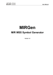
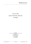
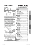
2.3.2 D/C and data connectors
The Alarm and data connectors of the L-Band Switch Matrix all are located at the rear side right hand of
the enclosure. The figure below illustrates the location of the connectors and the pin out.
The LED PS shows the presence of one or two power supply(ies), The LNK LED turns on, when there is
some traffic on the LAN, the matrix is connected to.
To release the MNC board, open the srews with which the card is fixed at the mounting rail. Now turn in
the screw into the screw thread beside to push the card out of its socket. After that you can pull the card out
of the unit.
To install the MNC board again, put it into the slide rail until the frontplate of the card contacts the
mounting rail. Please pay attention: The board has to slide in smoothly. If not, pull the card out and try
again. Otherwise the connector on the MNC board or on the backplane might be damaged.
After that fix the card with the provided screws to ensure a proper contacting of the connectors on the MNC
board with the connectors on the backplane.
J1.1 Alarm connnector
Pin Alarm contacts (DSUB-9 male)
1
NC1
closed if ok, open in fault state
2
COM1
common for fault relay 1
3
NO1
open if ok, closed in fault state
4
not connected
5
not connected
6
NC2
closed if ok, open in fault state
7
COM2
common for fault relay 2
8
NO2
open if ok, closed in fault state
9
not connected
J1.3 Serial connnector
Pin RS232 serial interface (DCE) (DSUB-9 female}
(C) 2013, SatService GmbH
www.satnms.com
LSM-UM-1301 Page 5/18
SatService
Gesellschaft für Kommunikationssysteme mbH
1
not connected
2
TxD (output)
3
RxD (input)
4
internally bridged to pin 6
5
GND
6
internally bridged to pin 4
7
internally bridged to pin 8
8
internally bridged to pin 7
9
not connected
J1.2 Network Connector
Ethernet 10/100Base-T (RJ45
2.3.3 RF connectors
On the rear side you can find the RF-connectors left hand. On the left side the L-Band output connectors
are located, on the right side of these connectors you can find the RF-input connectors.
In the standard configuration all RF-connectosr are SMA/ 50Ohm female connectors. If you need other
connectors e.g. BNC or F or an 75Ohm impedance, contact us, we are able to offer the corresponding
adaptors and inpedance transformers.
Switch- and Distribution-boards
With these two types of boards, the L-Band switch Matrix is realized. On the back side of the L-Band
Switch Matrix you find the Switch-boards, on the front side (when the Frontpanel is opened) you can see
the Distribution boards. How they work together is described in chapter Theory of Operation .
These boards are hot-plugable, so they are able to be changed while the L-Band switch matrix is working.
Switch Board
The switch board switches the selected RF Input Signal to its RFout. The switch boards are available as 8way, 16- way and 32 way version. Of every version there are 2 different cards avaliable: as you can see in
the following pictures, the RFout connector is shifted. The internal build-up is the same, it is only to optimize
the handling with the cards. If you mount them alternating, there is more space to handle the connectors. It
is also possible to replace a type1 through a type2 card without any problems.
To release a switch board, open the srews with which the card is fixed at the mounting rail. Now turn in the
screw into the screw thread beside to push the card out of its socket. After that you can pull the card out of
the unit.
Please pay attention: Before installing a switch board, ensure that the MMBX plugs are all in the same
direction, otherwise they may be damaged during the insertion-withdrawal operation. To install a switchboard,put it into the slide rail until the frontplate of the card contacts the mounting rail. The board has to
slide in smoothly. If not, pull the card out and try again. Otherwise the connectors on the card edge might be
damaged. After that fix the card with the provided screws to ensure a proper contacting of the connectors
on the switch board with the connectors on the corresponding ports on the distribution boards.
Connector description
BPYin
This input is reserved for further extensions (e.g. a 64x64 Matrix). With a customized
software it is possible to switch the signal that is supplied to this
RFout
The selected RF input Signal is switched to this connector
A switch board displays the following states:
{parameter} description
PS
the green power supply LED switches on, as soon as the power supply of the card is
working.
FLT
the red fault LED switches on, if a fault occurs on the internal RF circuit.
Distribution board
The distribution board distributes the connected RF input signal to every connected switch board. These
boards are available as 8-way, 16-way and 32-way version.
The picture above shows the view onto a 8x8 L-Band switch Matrix which frontplate is opened. On the left
side you can see the power supplies, on the right side the distribution boards are installed. The installation
order is from bottom (#1) to top (#8, #16 or #32).
ATTENTION: if you change a distribution board while the L-Band switch Matrix is running, the mains
voltage is available on the power supplies!
The connectors of the L-Band inputs located on the rear panel of the matrix.
To remove a distribution board, open the 2 screws which with the metal bar, that holds the distribution
boards in its position, is fixed. Remove the cable connected to the board that you want to remove. Now you
can pull out the card carefully out of its slide.
To install a distribution board, put it into the slide rail until the card is in the same horizontal position as the
others. The board has to slide in smoothly. If not, pull the card out and try again. Otherwise the connectors
on the card edge might be damaged. After that fix the metal bar with the provided screws to ensure a proper
contacting of the connectors on the distribution board with the connectors on the corresponding ports on the
switch boards.
Every card contains 2 connectors:
Connector
description
SMA
RF input: the RF input signal to be distributed to the switch boards, has to be supplied here.
beside the
LEDs
SMA on Test output: on this connector the signal, supplied at the RF input connector, is provided
the
right here without attenuation. If not in use, terminate this output with a 50Ohm terminator.
hand
A distribution board displays the following states:
{parameter} description
green LED
the green power supply LED switches on, as soon as the power supply of the card is
working
red LED
the red fault LED switches on, if a fault occurs on the internal RF circuit.
2.4 Configuring the L-Band Switch Matrix
(C) 2013, SatService GmbH
www.satnms.com
LSM-UM-1301 Page 6/18
SatService
Gesellschaft für Kommunikationssysteme mbH
This chapter gives a short overview about some configuration parameters you want to set after you have
installed the sat-nms L-Band Switch Matrix. A complete reference of all available setup parameters is given
in chapter General Setup.
Number of the outputs/inputs
To let the L-Band Switch Matrix know the amount of inputs and outputs, you have to write the
corresponding values here. These parameters are set in the delivery state to the correct values.
Switch parameters
The 'Switch' page shows you the souces of the RF-outputs. If you want to change a connection, choose the
line of the output which source you want to change. Click on the displayed souce and choose the
connection that you like to have. After clicking the "SUBMIT"-Button, the conncetion changes to the
desired input.
It is possible to switch an input to more than one output without any Signal loss.
2.5 Mechanical installation
The L-Band Switch Matrix' enclosure is a standard 19" rack-mountable enclosure. Depending on the
configuration, the eclosure has a height of 3 HU (8x8 matrix), 6HU (16x16 matrix) or 9HU (32x32 matrix).
Use slide bars to install the L-Band Switch Matrix, because the mounting angles will not be able to hold the
L-Band Switch Matrix in the horizontal position. Fix the enclosure with according screws to a 19" Rack.
Don´t forget to connect the 'GND'-screw to the Rack.
The L-Band Switch Matrix will get warm during operation. To prevent an overheating leave at least 1HU
below and above the L-Band switch matrix to allow the rejected heat to dissipate.
(C) 2013, SatService GmbH
www.satnms.com
LSM-UM-1301 Page 7/18
SatService
Gesellschaft für Kommunikationssysteme mbH
3 Operation
The sat-nms L-Band Switch Matrix is designed to be controlled over a network link using a standard web
browser. This means in practice, that the user interface to the unit appears in your browser window after
you type in the units IP address in the address field of the browser program. Besides the network-operation
the L-Band Switch Matrix gives you also the possibility to control the unit by a keyboard and Display on the
Frontpanel of the L-Band Switch Matrix. For more informations read chapter Frontpanel Operation .
Operating the L-Band Switch Matrix is mostly self-explanatory.
3.1 The Web-based User Interface
After having connected the L-Band Switch Matrix to a power supply and set the Matrix IP address, you can
access the L-Band Switch Matrix user interface. To do this, start your favorite web browser program
(Internet Explorer, Netscape Navigator, Opera or what else Program you prefer). At the address field, where
you normally enter the URL of a web page you want to see, type in the IP address of the sat-nms L-Band
Switch Matrix you want to control.
The L-Band Switch Matrix shows a web page consisting of a navigation bar at the left side of the browser
window and the actual readings of the L-Band Switch Matrix in the main part of the window.
The navigation bar at the left contains five buttons which build the Matrix main menu:
Switch
By clicking this button the L-Band Switch Matrix shows the switch parameters. Here you can
configure, the souces for the RF-outputs.
Graphic By clicking to this button you switch to to the crosspiont-overview. Here you can switch and also
see graphically which input is switched to which output.
Alarm
log
The alarm log shows all occurred alarms with time and date.
Setup
This button switches to the 'Setup' page which lets you inspect or change less common
parameters which usually are set only once to adapt the L-Band Switch Matrix to it's working
environment.
Info
After a mouse click to this button, the L-Band Switch Matrix shows a table with information like
the serial number of the device or the revision ID and compilation date of the software.
Help
Clicking to this button shows the on-line version of this user manual
3.2 Switch parameters
The 'Switch' page shows you the souces of the RF-outputs. If you want to change a connection, choose the
line of the output which source you want to change. Click on the displayed souce and choose the
connection that you like to have. After clicking the "SUBMIT"-Button, the conncetion changes to the
desired input.
It is possible to switch an input from one up to all outputs without any Signal loss.
3.3 Graphic switch parameters
After clicking the "Graphic" button you can see the connection overwiev in a graphical Dot-Matrix. The
lines represent the inputs, the rows belong to the outputs. If you want to change a source for an output, just
click on the according crosspoint, and the L-Band Switch Matrix will immediately switch the choosen input
to the selected output.
It is possible to switch an input from one up to all outputs without any Signal loss.
3.4 General Setup
The page 'Setup' contains the L-Band Switch Matrix installation parameters. Installation parameters are
those which are assumed to be changed less frequently than the operational parameters on the 'switch' or
'graphic' page.
The page displays a table with the parameters actually set. Each parameter value is a hyper-link to a separate
page which lets you change this parameter. This parameter change page shows the actual parameter setting
either in an entry field or in a drop down box. You may change the parameter to the desired value and then
click to the 'Submit' button to pass the changed value to the The L-Band Switch Matrix. The L-Band
Switch Matrix automatically returns to the setup page when the parameter has been changed. To cancel a
parameter modification you already started, either use the 'Back' button of you web browser or click to the
'Setup' button on navigation bar. Both returns to the setup page without changing the parameter you edited.
The table below lists the settings provided by this page.
Parameter
Name
Description
General
Type of Frame
The Type of the LSM frame: matrix for all switch matrix models and switch for the N:1
switches.
Date/ Time
If you want to set the Date and/ or the Time, type the actual Date and Time in the
following syntax: YYYY-MM-DD HH:MM:SS It is not possible to change only one of
both parameters.
refresh graph
Here you can configure the refesh-time for the Dot-Matrix Graph that shows the
sources for the outputs. You can choose between "5s", "10s" and "none". If "none"s
selected, the graph will not be refreshed, when a setting is chaged via remote control or
frontpanel operation, until you press the refresh-button of you browser or until you
press the 'Graphic'-button again.
Number of the Set here the number of available outputs of the The L-Band Switch Matrix
outputs
Number of the Set here the number of available inputs of the The L-Band Switch Matrix
inputs
Interface
baudrate
select here the bit rate for the RS232 Interface. You can choose between 9600, 19200,
38400, 57600, 115200 baud
Communication This parameter defines the communication address to be used with the serial interface.
adress
You may select an address 'A' .. 'G' for the packet mode communication protocol or
'NONE' to switch the communication mode to a plain text protocol.
Display mount with this parameter you can select if the display is mounted in horizontal or vertical
direction
direction.
Input names
you can assign a name with up to 20 characters to every input.
Output names
you can assign a name with up to 20 characters to every output.
SNMP
Configuration
Read
Community
Sets the SNMP community string expected for read access. The default is 'public'.
Write
Community
Sets the SNMP community string expected for write access. The default is 'public'.
Trap
Community
Sets the SNMP community string sent with traps. The default is 'public'.
Trap
Enter the trap destination IP address (dotted quad notation) to make the L-Band Switch
Destination IP Matrix sending traps by UDP to this host. Setting the parameter to 0.0.0.0 disables the
1
trap generation.
Trap
Enter the trap destination IP address (dotted quad notation) to make the L-Band Switch
Destination IP Matrix sending traps by UDP to this host. Setting the parameter to 0.0.0.0 disables the
2
trap generation.
Trap
Enter the trap destination IP address (dotted quad notation) to make the L-Band Switch
Destination IP Matrix sending traps by UDP to this host. Setting the parameter to 0.0.0.0 disables the
3
trap generation.
Trap
Enter the trap destination IP address (dotted quad notation) to make the L-Band Switch
Destination IP Matrix sending traps by UDP to this host. Setting the parameter to 0.0.0.0 disables the
4
trap generation.
System
Location
The L-Band Switch Matrix replies to MIB-II sysLocation requests with the text entered
at this place.
System Contact The L-Band Switch Matrix replies to MIB-II sysContact requests with the text entered
(C) 2013, SatService GmbH
www.satnms.com
LSM-UM-1301 Page 8/18
SatService
Gesellschaft für Kommunikationssysteme mbH
at this place.
Access
Control
User password
Here you can define the password for the 'user' login. Default password is 'user'. When
you are logged in as 'user' you are only able to change the parameters on the 'Switch'
and 'Graphic' pages. All the other paramters can only be changed when you are logged
in as 'admin'
Admin
password
Here you can define the password for the 'admin' login. Default password is 'admin'.
When you are logged in as "admin" you are only able to change all the paramters of the
unit.
Real Time Clock battery backup
The L-Band Switch Matrix real time clock is backed up by a goldcap capacitor. The goldcap supplies the
RTC chip with power for several days if the main power is missing. This is the preferred mode of RTC
backup for stationary installations of the L-Band Switch Matrix.
For applications where the L-Band Switch Matrix is powered up only occsionally, a lithuim cell may be
connected inside the L-Band Switch Matrix housing in order to provide a permanent buffering of the clock.
3.5 Frontpanel Operation
The front panel of the L-Band Switch Matrix provides a LCD and a small keyboard for operating the
device locally.
Display The graphic display normally shows the actual sources for the L-Band Outputs.
LEDs
Three LEDs at the front panel signal the summary state of the L-Band Switch Matrix.
The 'Remote' LED is on while the unit is controlled from a remote computer via network or serial
interface. There is no exclusive remote or local lockout mode with the sat-nms L-Band Switch Matrix.
Local operation of the L-Band Switch Matrix is still possible while the device is accessed remotely.
The 'Remote' LED is just an information, that someone from remote talks to the device and a local
change of parameters may interfere with this.
The 'Test' LED should not be on during normal operation of the unit. If the 'Test' LED is on, there
has occurred a latched fault. A latched fault means, the fault has been there but it doesn´t exsist no
longer. So the 'Test' LED is on to inform you that there has occurred a fault. You can see in the
'Alarm log'which fault occurred.
The 'Alarm' LED is on while the unit is in alarm state. This is the same condition which controls the
fault relay output.
Keys
The front panel keyboard provides beside the numeric keys four arrow keys and two keys named ENTER
and CLEAR. The general meaning of the keys remains constant through all levels of the menu:
The ENTER key descends in the menu tree, accepts and stores changed values.
The CLEAR key leaves to higher menu levels, abandons changes when editing parameters. It also
resets the alarm buzzer when in display mode.
The arrow keys navigate in the menu, in some cases they also increment / decrement values.
0 .. 9
The number keys are to enter numeric parameters.
3.5.1 Connection Display
After starting the L-Band Switch Matrix the Display shows the sources of the RF-outputs. At the bottom of
the display you can see the summary state of the The L-Band Switch Matrix.
To change a source press one of the
keys. After that you can move with the
to the output, which source you want to change.
Then press
keys the cursor
. Now you can select which input should be switched to the selected output.
After choosing the input via the
keys, press
, for switching to the selected input.
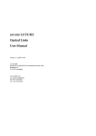
3.5.2 The Main Menu
The menu lets you view and change the L-Band Switch Matrix settings. From the Connection display mode,
you enter the menu by pressing the .i enter.gif key.
To select a sub-menu, move the cursor with the
enter the selected sub-menu.
To leave the menu, repeatedly press the
keys to the desired target. Press the
key to
key until the Connection display screen appears again.
The menu structure is shown in the screenshot below:
3.5.2.1 Set Crosspoints
After entering this sub-menu it is possible to change the sources for the RF-Outputs. To change a source
press one of the
keys to move to the output, which source you want to change.
(C) 2013, SatService GmbH
www.satnms.com
LSM-UM-1301 Page 9/18
SatService
Gesellschaft für Kommunikationssysteme mbH
Then press
. Now you can select which input should be switched to the selected output
After choosing the input via the
laving the sub-menu without saving.
keys, press
, for switching to the selected input, press
for
3.5.2.2 Clear All Crosspoints
With entering this sub-menu you can delete all crosspoints, and set all sources for the RF-outputs to 'none'.
Press
for deleting all crosspoints, press
for leaving this sub-menu without deleding the crosspoints.
3.5.2.3 Interface Baud Rate
Select here by using the
keys, the bit rate for the RS232 Interface. You can choose between
'disabled', 9600, 19200, 38400, 57600, 115200 baud.
Press
saving.
, for configuring the baud rate to the selected value, press
for laving the sub-menu without
3.5.2.4 Communication adress
This parameter defines the communication address to be used with the serial interface. You may select by
using the
keys, an address between 'A' and 'G' for the packet mode communication protocol or
'NONE' to switch the communication mode to a plain text protocol.
Press
, for configuring the communication adress to the selected value, press
menu without saving.
for laving the sub-
3.5.2.5 Alarm log
The alarm log shows all occurred alarms with time and date. If there are more than 10 faults, you can sroll
with the
keys up and down in the faults-list.
3.5.2.6 Clear Latched Faults
To clear the latched faults, enter sub-menu 'Clear latched faults'. With entering this sub-menu you can
delete the latched faults indication (Test-LED). Press
for deleting the latched faults indication, press
for leaving this sub-menu without deleding the latched faults indication.
(C) 2013, SatService GmbH
www.satnms.com
LSM-UM-1301 Page 10/18
SatService
Gesellschaft für Kommunikationssysteme mbH
3.5.2.7 Date / time
In this sub-menu you can change the Date and time-settings. Move the cursor with the
keys to the
value that you want to change and press
. Now you can type the desired value via the number-keys.
Press
to save the value or
to abolish the setting. After setting all the values scroll with the
keys down to 'accept' and press
to save the values.
3.5.2.8 Unit / manufacurer info
This displays contact informations to the manufacturer SatService GmbH and shows the installed softwareversion.
3.5.3 Editing Numeric Parameters
To change a numeric parameter like the Date or Time, select this value from menu.
To set a new value, press
. This clears all figures from the value display and shows '0' at the first
column to signal the editing mode. Using the number keys, you enter the new value. The digits fill the entry
field from right to left, like with a pocket calculator.
To accept the edited value, press
. This checks the entered value against it's limits and executes the
parameter change. Pressing
once leaves the editing mode without changing anything.
3.5.4 Editing Multiple Choice Parameters
To change a numeric parameter like the RS232 interface baudrate, select this value from the menu. To set a
new value, use the
keys to select the desired value.
To accept the changed value, press
. Pressing
leaves the editing mode without changing the value.
(C) 2013, SatService GmbH
www.satnms.com
LSM-UM-1301 Page 11/18
SatService
Gesellschaft für Kommunikationssysteme mbH
4 Remote Control
T h e sat-nms LSM L-Band Switch Matrix may be controlled remotely by a monitoring and control
application either through the TCP/IP interface or through a serial RS232 interface. Both communication
methods use the same commands and parameters, however, there are different frames around each message
depending communication method used. The third method is SNMP.
Controlling the device from the web interface, the TCP/IP remote control interface, the SNMP interface or
via the serial interface is completely equal, commands may sent to any interface at any time, the LSM will
use the parameter it receives last.
4.1 General command syntax
The LSM knows a number of parameters, each identified by a parameter name. To set a certain parameter
to a new value, a message:
name=value
has to be sent to the L-Band Switch Matrix. The LSM interprets this command, checks the range of value,
sets the internal parameter and then answers:
name=value
T he value in the reply is the value actually recognized by the L-Band Switch Matrix. For instance, if the
requested value was out of range, the replied (and internally used) value is limited to the applicable
minimum or maximum.
To read a parameter from the L-Band Switch Matrix, instead of a new parameter value a question mark is
sent:
name=?
The L-Band Switch Matrix replies the actual value in a complete message:
name=value
A complete list of the parameter the L-Band Switch Matrix knows is shown later in this document in chapter
Parameter list. Below, some common rules applying to the remote control message syntax are summarized.
Parameter names always are of lower case letters, most of them are four characters long.
Non-numeric parameter values always are written in upper case.
Numeric (floating point) values may be specified with an arbitrary precision, however the device will
reply only a fixed number of places. The LSM recognizes a decimal point ('.'), numbers must not
contain any commas.
There must not be any whitespace in front or after the '=' in a message.
If the command/query is not of the form name=value or name=?, the LSM replies the message ?
SYNTAX.
If the message syntax is OK, but contains an unknown parameter name is used, the reply is ?
UNKNOWN
Numeric parameters are cut to the limits defined for this particular parameter.
Misspelled choice values cause the LSM to set the first value of the choice list.
Assigning a value to a read-only parameter will cause no fault, however the LSM will overwrite this
parameter immediately or some seconds later with the actual value.
4.2 The TCP/IP remote control interface
Controlling the L-Band Switch Matrix through the network is done by means of HTTP GET requests.
Setting parameter values or querying readings or settings, all is done by requesting HTTP documents from
the matrix. The message to the LSM thereby is coded into the URL as a CGI form parameter. The L-Band
Switch Matrix replies a one line document of the MIME type 'text/plain'.
The document name for remote control is /rmt, hence (assuming the LSM is listening to the IP address
10.0.0.1), requesting a document with the URL
http://10.0.0.1/rmt?sver=?
will let the LSM reply the software version in a one line text document:
sver=1.010 2007-10-04
This way all parameters may be queried or set, you may use your favorite web browser to try out the
remote control of the LSM manually.
4.3 The RS232 remote control interface
Beside the network interface, the L-Band Switch Matrix also provides an RS232 serial port which can be
used to control the device remotely. Depending on the device address set, the LSM either runs framed
protocol with start/stop characters and checksum or it provides a dumb terminal interface. The RS232
interface operates by default at 9600 baud, no parity, 8 data bits, one stop bit.
You can configure the baud rate on the front panel.
If an address 'A' .. 'G' is selected, the LSM expects each message it receives to be packed into a frame as
described below.
char # example description
1
{
start character, always '{'
2
A
device address (A..G)
3
t
first character of the message body
.
m
message body ...
.
p
..
.
0
..
.
=
..
n-1
?
last character of the message body
n
}
end character, always '}'
n+1
.
checksum
The checksum byte is calculated using an algorithm as implemented by the following formula:
This protocol type is known as MOD95- or Miteq protocol . The LSM also packs it's reply in a protocol
frame as described above. incomplete frames, checksum errors or address mismatches let the LSM ignore
the message. The time between the characters of a message must be less than 5 seconds or the LSM will
treat the message as incomplete.
If the LSM is set to the device address 'NONE', it uses a simple line protocol instead of the framed protocol
described above. Messages sent to the LSM have to be terminated with a carriage return character (ASCII
13), the LSM terminates replies with a CR/LF pair (ASCII 13/10). There is no echo for characters entered,
hence this protocol easily may be used for computer based remote control.
4.4 SNMP Control
The L-Band Switch Matrix contains an SNMP agent listening at UDP port 161. The SNMP agent provides
a common subset pf the MIB-II system / interface parameters and gives full access to the remote control
capabilities of the LSM with a number of MIB objects placed in the private.enterprises tree.
The actual MIB file defining the switch matrix private MIB may be downloaded from the unit istelf by FTP
(user 'service', password 'service'). The file 'LSM.MIB' contains all neccessary information. A link to this
MIB file is also included in the web interface on the 'setup page'.
4.5 Parameter list
The table below shows the complete list of M&C parameters the L-Band Switch Matrix knows. For each
parameter the valid range and a short description is given.
(C) 2013, SatService GmbH
www.satnms.com
LSM-UM-1301 Page 12/18
SatService
Gesellschaft für Kommunikationssysteme mbH
name
range/format
description
addr
r/w
A,B,C,D,E,F,G,none
Communication address
autr
r/w
enabled,disabled
SNMP enable Auth traps
baud
r/w
disabled,9600,19200,38400,57600,115200 Interface baudrate
clir
o/w
disp
r/w
vertical,horizontal
Display mount direction
getc
r/w
[see below]
Position of Switches
hflt
r/o
[see below]
Matrix faults
hwcf
r/o
[see below]
Plugged/unplugged Cards
type
r/w
[matrix,switch]
type of the LSM frame
ninp
r/w
nout
r/o
rfgr
r/w
setc
o/w xx,yy
Set Crosspoint
srno
r/o
Device serial no
stim
o/w YYYY:MM:DD hh:mm:ss
Set date / time
sver
r/o
Software version
time
r/o
sdes
r/o
SNMP System description
scon
r/w
SNMP System contact
snam
r/w
SNMP System name
sloc
r/w
SNMP System location
rcom
r/w
SNMP read community
wcom r/w
SNMP write community
Clear all crosspoints
Number of the Inputs
Number of the Outputs
5 s,10 s,none
YYYY:MM:DD hh:mm:ss
Refresh Graph
Date / time
tcom
r/w
ipt1
r/w
aaa.bbb.ccc.ddd
SNMP trap community
SNMP Trap IP 1
ipt2
r/w
aaa.bbb.ccc.ddd
SNMP Trap IP 2
ipt3
r/w
aaa.bbb.ccc.ddd
SNMP Trap IP 3
ipt4
r/w
aaa.bbb.ccc.ddd
SNMP Trap IP 4
in08
r/w
[name01],..,[name08]
port names input 1-8
in16
r/w
[name09],..,[name16]
port names input 9-16
in24
r/w
[name17],..,[name24]
port names input 17-24
in32
r/w
[name25],..,[name32]
port names input 25-32
on08
r/w
[name01],..,[name08]
port names output 1-8
on16
r/w
[name09],..,[name16]
port names output 9-16
on24
r/w
[name17],..,[name24]
port names output 17-24
on32
r/w
[name25],..,[name32]
port names output 25-32
Fault Message
The command 'hftl' returns a text string which shows the fault status of the switch matrix.
Syntax: I[distribution board faults]O[switch board faults]P[power supply faults]
The length of the distribution board faults and switch board faults lists depends on the number of inputs
and outputs. The fault state for each input and output is shown by the character at the appropriate position,
where 0 means OK and 1 means FAULT. The power supply faults list contains 4 characters for power
supply 1 to 4.
http://192.168.2.81/rmt?hflt=?
hflt=I11000000O0000100001000010P0101
The example shows an 8x16 matrix, where the distribution boards 1 and 2, the switch boards 5, 10 and 15
and the power supplies 2 and 4 have faults.
Switch Positions
The command 'getc' returns a comma separeted list of the position of all switches. The following example is
from a switch matrix with 32 inputs and 8 outputs (32x8).
http://10.0.0.1/rmt?getc=?
This returns for each output (in this case for 8 outputs) which input is switched to this output.
getc=05,20,05,16,05,32,32,00
This means: Output 1 is connected to input 5, output 2 is connected to input 20 and so on. Output 8 is
connected to nothing (0).
Beginning with firmware version 1.5.018 the getc command allows also to set all switches with one single
command.
Plugged/unplugged Cards
The command 'hwcf' returns a comma separeted list of the state of all boards. The following example is
from a 8x8 switch matrix where the first distribution board (input) is not installed.
http://10.0.0.1/rmt?hwcf=?
This returns for each distribution output (in this case for 8 outputs) which input is switched to this output.
hwcf=I01111111O11111111
(C) 2013, SatService GmbH
www.satnms.com
LSM-UM-1301 Page 13/18
SatService
Gesellschaft für Kommunikationssysteme mbH
5 Theory of Operation
The switch matrices consists of the following main modules:
RF-Distribution Module
RF-Switching Module
Controller Module
Redundancy Power Supply
5.1 Distribution module
The RF-Distribution module divides the input signals in 'n' output signals ('n' depends on the size of the
matrix e.g. 8x8). Integrated MIMIC amplifier compensate the distribution losses of each sub module. Each
distributor module includes of a set of Wilkinson Divider in Coplanar design. This design is very reliable
with the following features:
High port to port isolation
Amplitude Flatness over the whole L-Band frequency range
To achieve high port to port isolation and support also a matrix which is only equipped with a subset of
modules each distributor output port is routed via a termination switch which provides a good return loss
also in case where no other cards are connected.
5.2 RF Switch module
The RF-Switch Module collects 'n' distributed input signals and allows the user to link a selected signal to
the output. The switch module is therefore connect with its input ports to one output port of each
distribution board. At the input of these modules there are GasFet SPDT absorptive Switches in combination
with 6:1 pin diode switches to handle the requested high suppression of each input. Again MIMIC amplifiers
are used on each board to compensate the loss in the signal path. The Switch Boards are controlled via a
serial data bus which is plugged on the Controller Module.
5.3 Controller Module
The Controller Module of the Switch Matrix is based on a separate 100x160mm printed circuit board and
the same for all types of switch matrices. It performs the following functions:
Monitor the RX-Distribution Modules
Monitor and Control the RX-Switch Modules
Calculate the position of each dedicated Switch for the Output Setting
Restore the switch position
Control the keyboard and display at the unit
Control the Remote Interfaces (RS232 and LAN)
The design of the monitoring & control board is based on the same controller with inetgarted web server
which SatService has sucessfully used in all other products of the sat-nms family as well. The chip has the
following advantages:
Real Time Operation System with FTP, HTTP, SNMP over TCP/IP
Two Serial Interfaces
(C) 2013, SatService GmbH
www.satnms.com
LSM-UM-1301 Page 14/18
SatService
Gesellschaft für Kommunikationssysteme mbH
No external RAM and ROM components
10BaseT RJ45 Interface
5.4 Mechanical Design
The following picture shows the mechanical connections of a RF-Distribution and a RF-Switch modules:
For all switch matrices up to 32x32 the matrix consists of n x 1:n RF-Distribution Modules and n x n:1
Switch Modules for each type of matrix, which will be mechanical combined in the following way (see here
at the example of a 8x8 matrix):
That implements that the following types of sub-modules are available: Distribution and Switch Boards:
8x8
16x16
32x32
Matrix systems which are bigger than 32x32 will be done by a combination of n x 32x32 complete matrices.
The reason for the size limitation to a 32x32 matrix is the handling of the PCB board size. The dimensions
of a board of 32x32 matrix is about 340mm, which is maximum of the open space size of a 19" rack.
A 64x64 matrix consists of four 32x32 Matrixes and a 128x128 Matrix consists of 16 times 32x32 matrices
plus a set of 8 32:1 switch boards. Also unsymmetrical versions like 64x32, 128x32 or 128x64 can be easily
realized by this scheme. The general building block in our foreseen design will always be a 32x32 matrix.
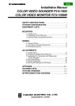
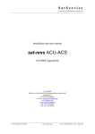
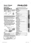
The attached block diagram shows the arrangement of a 128x128 matrix. In order to not overload the block
diagram we have drawn a simplified interconnection scheme which shows only the cable number 1 and 32
of each switch matrix box. In the lower center of the block diagram at the output ports of the switch matrix
you find the 8 output switches which combine the signals to the 128 output ports. In case of a 64x64 switch
matrix this additional output switches are not necessary as they are already integrated in each 32x32 switch
matrix itself. The configuration of a 64x64 switch matrix is marked in the upper left corner of the same
block diagram.
5.5 Outline Drawings and Model variants
3 HU unit
inputs outputs
8
8
8
16
8
32
16
8
32
8
(C) 2013, SatService GmbH
www.satnms.com
LSM-UM-1301 Page 15/18
SatService
Gesellschaft für Kommunikationssysteme mbH
6 HU unit
inputs outputs
16
16
16
32
32
16
9 HU unit
inputs outputs
32
32
(C) 2013, SatService GmbH
www.satnms.com
LSM-UM-1301 Page 16/18
SatService
Gesellschaft für Kommunikationssysteme mbH
(C) 2013, SatService GmbH
www.satnms.com
LSM-UM-1301 Page 17/18
SatService
Gesellschaft für Kommunikationssysteme mbH
6 Specifications
RF Specification
Frequency range
950 to 2150MHz
L-Band Input Connectors
SMA female 50Ohm
L-Band Output Connectors
SMA female 50Ohm or F Female 75
Ohm
Input Return Loss
> 17dB
Output Return Loss
> 17dB
Input Noise Figure
< 13dB
Gain
0 +/-1dB
Flatness
+/-1.5 dB,
+/-0.25dB in any 40MHz
Gain Stability
+/-0.25dB/24h
OIP3
> +10 dBm
Intermodulation at -13dBm Input Level
<-40 dBc
Isolation
Out->In 50dBc,
Out->Out 40dBc
M&C Interface Specification
Ethernet interface for M&C and user interface
10-Base-T, Via http GET requests
Front panel display
graphical LCD 16x32
RS232 M&C Interface
D-SUB 9 female
Summary fault indication
Relay contact D-SUB 9 male
Electrical and Mechanical Specification, Environmental
conditions
Supply Voltage
90 to 230V, AC 50 to 60Hz
Connector for the two mains voltage AC inputs
IEC
Temperature range
+10° to +40°C
Humidity
up to 90% non condensing
Mechanical size
8x8: 436 x 132,5 x 400 mm, 19" 3HU
16x16: 436 x 265,0 x 400 mm, 19”
6HU
32x32: 436 x 399,2 x 400 mm, 19”
9HU
(C) 2013, SatService GmbH
www.satnms.com
LSM-UM-1301 Page 18/18