1
THE WYLE SCIENTIFIC
MAINTENANCE AND SERVICE MANUAL
JUNE
SM-666-100
WYLE LABORATORIES
1966
Copy 35
ProJucts DIvision· I .:n Center Street. EI Segundo. Calif. 90245 • Phone (213)
OREGON
8-4251 I TWX 910-348-6283
TABLE OF CONTENTS
INTRODUCTION
SPECIFICATIONS
SECTION 1:
OPERATING INSTRUCTIONS
SECTION ll:
THEORY OF OPERATION
1. 0
Block Diagram Analysis
1.1
Timing
1. Z
Memory
1.3
Arithmetic Section
1.4
Function Storage and Function Control
1. 5
Display Section
2. 0
Summaries of Function Routines
2 1
Numeral Entry Routine
2. 2
Alignment Routine
2. 3
Transfer Routine
Z.4
Forward Space Routine
Z, 5
Back Space Routine
Z,6
Clear Multiplier-Quotient Register Routine
Z, 7
Clear Entry Register Routine
Z. 8
Clear Accumulator Register Routine
Z. 9
Shift Left Routine
Z. 10
Shift Right Routine
2. 11
Addition Routine
Z. 1 Z
Subtraction Routine
Z. 13
Multiplication Routine
Z.14
Division Routine
Z. 15
Z. 16
Square Root Extraction
Edit Routine
t
WYLE LABORATORIES
Products Division· 133 Center Street. El Segundo. Calif. 90245 • Phone (213)
OREGON
8-4251 ITWX 910-348-6283
I
--------._- .... _.- __ _----_._--_._--------------------_._---------------------,
..
._..
i
I
i
TABLE OF CONTENTS (CONTINUED)
SECTION III:
PERFORMANCE PROCEDURE AND
MALFUNCTION SYMPTOMS
SECTION IV:
DISASSEMBLY, ALIGNMENT,
ADJUSTMENT PROCEDURES
SECTION V:
PARTS LIST
SECTION VI:
SCHEMATICS AND DRAWrnGS
AND
Figure 6-1
V Counter
Figure 6-2
V Count Decoder
Figure 6- 3
Sub-Bit Timing
Figure 6-4
Bit Counter
Figur e 6- 5
Bit Count Decoder (two sheets)
Figure 6-6
Bit Timing
Figure 6-7
Digit Counter
Figure 6- 8
Digit Count Decoder (two sheets)
Figure 6- 9
Digit Timing
Figure 6-10
Kp Logic
Figure 6-11
C Counter
Figure 6-12
K
Figure 6-13
and KI
DC
DC
Word Counter
Logic
Figure 6-14
A Counter, M Counter,
AC In, AC I In, and MC In Gates
Figure 6-15
A Counter
Figure 6-16
M Counter
Figure 6-1 7
R Counter
Figure 6-18
C Counter Input Gates
Figure 6-19
FC Logic
Figure 6-20
Cycle Counter
Figure 6-21
Cycle Count Decoder and Inhibit Logic
l
WVlE LABORATORIES
Products Division • 133 Center Street. EJ Segundo, Calif. 90.!.45 • Phone (213)
OREGON ~-4251
ITWX 910-348-6283
1~~--" ~-.-~.~,-~
.. - . - - . -
!
TABLE OF CONTENTS
SECTION VI:
SCHEMATICS AND DRAWINGS
Figure 6- 22
~ b 2 Generator
Figure 6- 23
LO Logic
Figure 6- 24
OF Logic
Figure 6- 25
Clear Logic
Figure 6-26
DeITlultiplexer Logic
Figure 6-27
R S
Figure 6-28
,
.,. .•
~.v·,_
... .
_~,<o_~_.
(CONCLUDED)
Logic
w
Shift Left, Recirculate Logic
Figure 6-29
Record New /Processed Data,
Shift Right, Erase Logic
Figure 6- 30
Function Control Logic
Figure 6-31
"TO" and "FROM" Storage and Control
Logic
Figure 6- 32
NC Input "TO" Brightener
and "FROM" Brightener Logic
Figure 6-33
Character (N) Counter, Storage (Q)
Reg ister, and Decoder Logic
Figure 6- 34
Optical Coder
Figure 6- 35
Card Reader
Figure 6- 36
Delay Line Calculator Keyboard
__ •• _ _ _ _ _
lABORATORIES
Products Division' 133 Center Street. El Segundo, Calif. 90245 • Phone (213)
OREGON
8-4251 ITWX 91 0-348-62~3
INTRODUCTION
The Wyle Scientific is a digital electronic calculator with a delay line memory
capable of operating on six fixed-length registers and performing addition,
subtraction, multiplication, division, and square root extraction functions.
Operational input is via a 38-key keyboard and output is displayed in a CR T
presentation of the contents of all memory registers.
Provision has been made for addition and connection of external peripheral
systems including input, programming, and memory devices.
This manual contains operational, programming, and maintenance information
for the Wyle Scientific Model WS-02 and is summarized as follows:
Section I:
Operating Instructions
Detailed explanation of keyboard functions, data display
identification, and associations used in programming.
Section II:
Theory of Operation
Complete functional analysis of operations performed by
the calculator with reference to block and flow diagrams.
Section III:
Performance Procedure and Malfunctions Symptoms
A keyboard test program is provided to functional1y check
the calculator for correct operation. Malfunction symptoms
and possible causes are listed in tabular form.
Section IV:
Disassembly, Alignment, and Adjustment Procedures
Step-by-step instructions for removal and/ or replacement
of special assemblies or components are outlined. Critical
alignment procedures of the read and write circuits and of
the delay line, and adjustments of the special display circuits
are included.
Section V:
Parts List
Component types and values are listed for replacement
purposes.
Section VI:
Schematic s and Dr awing s
Wiring diagrams and schematics of al1 printed circuit boards
with associated flow diagrams are included.
WVLE LABORATORIES
Products Division· 133 Center Street. EI Segundo. Calif. 90245 • Phone (213)
OREGON
X-42S1 IT\VX 910-348-6283
SPECIFICATIONS
Machine Type:
Electronic desk calculator
Memory:
4. 85-millisecond magneto-strictive delay line
Number of Registers:
Three arithmetic and three storage registers.
(Up to 24 additional storage registers are
available as peripheral equipment. )
Length of Registers:
Twenty-four digits
Decimal Point:
Automatic and presentable by operator
Negative Sign:
Nine t S complement
Logic Elements:
Solid state
Functions Available:
Add
Subtract
Clear and Multiply
Multiply Plus
Multiply Minus
Division
Square Root Extraction
Shift Left
Shift Right
Back Space
Forward Space
Transfer
Clear Registers
Numeral Entry
Decimal Point Alignment
Power Reguirements:
105/125 vac, 60 cycles, 170 watts
220/260 vac, 50 cycles, 1 70
watts>~
90/110 vac, 50 cycles, 170 watts*
Winchester Part MRAI04S (104-pin)
Peripheral Connector:
*Optional on special order
J
WYLE LABORATORIES
Products Division
e
133 Center Street. El Segundo, Calif. 90245 • Phone (213)
OREGON
R-4251 /TWX 91 O-J48-62XJ
__.._._----\
.
i
I
Ii
I
I
II
I
SPECIFICATIONS (CONCLUDED)
Speed of Operations:
I
I
I
Add
Subtract
Multiply>:<
Divide~<
Square Root*
De cimal Point
Alignment>t'<
Shift Left
Shift Right
Back Space
Forward Space
Transfer
Clear Register
Numeral Entry
Peripheral Equipment
(Optional) :
i
4.8 milliseconds
4. 8 millis econds
Less than 1 second
Less than 1 second
Less than 1 second
I
Les s than 0.2 second
4.8 milliseconds
4.8 milliseconds
4.8 milliseconds
4.8 milliseconds
4.8 milliseconds
4.8 milliseconds
4.8 milliseconds
Punched Card Programmer PC-Ol
Patch Board Programmer PB-02
(maximum of 512 program steps)
Supplemental Memory Register SM-O lor ..
SM-02 (8 to 24 additional registers for
data storage)
Intercoupler and Auxiliary Keyboard WS IIC
):<Multiple -cycle functions which depend upon operand values and decimal
point position.
I
I
I
WYLE LABORATORIES
Products Division· 133 Center Street, El Segundo, Calif. 90245 • Phone (213)
ORHjON
J
~A251 ITWX 91 O-J,+8-6~~g3
SYSTEMS
DATA
wss-s
-
-;-:.-
WYLE SCIENTIFIC SYSTEM
Mode l WSS-S
INT RODU CT ION
The Mod e l WSS- S extends the capability of the basic Wyle Scientific Calculator through th e
addition of supp lementa l data storage registers. The WSS-S includes features which allow
easy upgrading of the WSS-S to the more powerful WSS-10. The additional data storage
reg isters simplify programming, increase the speed of program operation, and allow the
system to handle more complex problem s.
The Model WSS-S is tru ly modular, since the customer's existing Calculator and PC-Ol
Punched Card Programmer can be incorpo rated directly into the system. Any of the ma jor
system components can be directly replaced by another unit of the same type.
SYSTE M DESCRIPTION
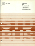
A block diagram of the WSS-S system is shown in Figure J. Th e basic element of the system
is the Wyle Scientific Calculator, Model WS-02. This un it pe rforms all arithmetic functions
and provides the basi c memory of the syste m, with three working registers and three storage
reg isters. Basic manual controls and a CRT display of the registers' contents a re also part of
the WS-02.
Programmi ng capability is pro vided by the Model PC-OJ Punched Card Programmer. The Model
PC-OJ provides a means of rapidly programming special applications and of building a large
Iibrary of programs.
Pr?gra.ms for th~ ~u.nch ed Card Prog.ram~er are now a vailable which permit signed algeb raic multiplication and divIsion. The operation IS fully automatic, requiring no decision or interference by
the ma chine operator.
A Supplemental Memory Unit, Mod el SM-OJ, provides eight additional data storage registers,
each with a capacity of 24 decimal digits. Data may be fre e ly transferred between these
registers and the s ix basic registers of th e WS-02. This transfer of information can be control.led by either the Punched Card Prog rammer or by the operator, via the Mo de l KB-Ol
S DS-S66-1 M
Perl phera I Input Ke yboard.
WVLE LABORATORIES
Products Division· 133 Center Street. EI Segundo. Calif. 90245 • Phone (213)
OREGON
8-425 I I TWX 910-348-6283
Two additional Supplemental Memory Units, Model SM-02, can be added, to provide a total
of 24 supplementa I registers.
The Model KB-Ol Peripheral Input Keyboard provides a channel for the flow of data and
instructions between the various units, and the Model KB-OT provides additional control
keys for manua I address i ng a f the supplementa I registers.
The Supplemental Memory is mounted in the pedestal section of the desk console. The WS-02,
the PC-OT, and the KB-OT are free-standing units which are placed on the desk, as shown in
the phvtograph.
TECHNICAL SPECIFICATIONS
1.
CALCULATOR Model WS-02
MEMORY
Six basi c registers. Three (MQ, Entry and Accumulator) working
registers and three (Rl, R2, and R3) data storage registers. Each
register has a capacity of 24 decima I di gits.
r - - - - r-----------.
I
ZONE
I
I
CALCULATOR
TRANSFER
MODEL WS-02
I (OPTIONAL)
IL ____ L..--_ _ _ _ _ _- - - '
....
.
KEYBOARD (KB-Ol)
PUNCHED CARD
AND
PROGRAMMER
I NTERCOUPLER
MODEL PC-Ol
(WS/I C-01)
r-------,
I
I
I
SUPPLEMENTAL
MEMORY
MODEL SM-02
I
1+ _.-...
I
IL _ _ _ _ _ _ _ ..J
(OPTIONAL)
r-----------,
I
-----...
I
SUPPLEMENTAL
MEMORY
MODEL SM-Ol
I
SUPPLEMENTAL
I
MEMORY
I
MODEL SM-02
I
I
~--+!
:
:
(OPTIONAL)
L
______
:
..J
FI GURE 1: MODEL WSS-5 BLOCK DIAGRAM
5D5-566-1 M
WYlE LABORATORIES
Products Division· 133 Center Street. El Segundo, Calif. 90245 • Phone (213)
OREGON
g-4251 ITWX 910-34~-62g3
DECIMAL POINT
Decimal locations selectable from 21 digits, 3 decimal
places to 3 digits, 21 decimal places, in increments of
3 digits.
OPERATIONS
In the operations list which follows, register designations are read as if preceded by "Contents ofll or IIresults
appear inll, as the case may be. For example (ACC) +
(Entry) - ACC is read as, IIContents of Entry are
added to contents of Accumulator and results appear in
Accumulatorll •
ARITHMETIC OPERATIONS
Add
Sub
Clear & Mult
Mult +
Mult Divide
(ACC)
(ACC)
(MQ)
(ACC) + [(MQ)
(ACC) - [(MQ)
+ (Entry)
x
x
x
(Entry)
(Entry)
(Entry)]
(Entry)]
JACC) / (Entry)]
{
(ACC)
-----
-
ACC
ACC
ACC
ACC
ACC
MQ
MQ
REGISTER ADDRESSING
Six instructions allow TO and FROM addressing of each
of the six basic registers. The TO addressing desig~
nates the register receiving data, whether the source is
the keyboard, or the programmers, or another register.
The FROM addressing designates the source of data for
register transfer operations.
II HOUSEKEEPI NGII
Shift Rig h t, Sh i ft Left
The contents of the register
addressed TO are shifted one
decimal place in the indicated
direction.
Forward Spa ce ,
Back Space
The position where the next
data digit is to be entered is
shifted one place right or left.
This allows correction of any
single digit in a 24-digit word.
Transfer
Contents of the regi ster
addressed FROM are copied
into the register addressed TO.
SD5-566-1M
WYI.E LABORATORIES
Products Division· 133 Center Street. EI Segundo, Calif. 90245
e
Phone (213)
OREGON
B-425 II TWX 910-348-6283
Clear MQ, Clear
Entry, Clear ACC
The contents of the indi cated
register are erased and that
regi ster is automati ca II y
addressed TO.
DATA ENTRY
Eleven instructions (or keys), representing digits 0 - 9
and decimal point, allow entry of numeric data.
Numbers are entered in the register addressed TO starting with the most significant digit. When the decimal
point instruction is received, the digits previously
entered align on the proper decimal point location.
Negative results of computation are represented in 10's
complement form. As an example:
-2 = 999----98.
MODE SELECT SWITCHES
Three slide switches on the WS-02 keyboard allow
manua I se lection of various operating modes.
KEYBOARD/DISPLAY
1.
ADD ANY REGISTER. In the OFF position, Entry
is added to the ACC when the ADD key is
depressed. In the ON position, the contents of the
register addressed FROM are added to ACC when
ADD key is depressed. Subtraction operates in a
simi Iar fashion.
2.
OVERFLOW LOCK OF F. With overflow lock on,
the machine IIhangs Upll when results of a computation exceed capacity of a register. With lock
off, the machine loses the most significant digits
but does not hang up.
3.
KEEP REMAINDERS. Remainders are retained after
division and square root operations. See WS-02
Operation Manual for detai led discussion.
The basi c keyboard and display are part of the WS-02.
The keyboard allows manual control of all operations
previously described. The CRT display gives a continuous visual indication of the contents of the six basic
registers and, in conjunction with the Peripheral Input
Keyboard Model KB-01, an lion demand 'l display of the
contents of supplementa I registers.
SD5-566-1M
WVLE LABORATORIES
Products DivisiOll" !
( 13)
OREGON ~--4251
ITWX 91 O<j
•
(
II.
PERIPHERAL INPUT KEYBOARD Model KB-Ol
KEYBOARD
The KB-Ol provides an auxiliary manual keyboard used
for addressing th e supplementa I storage registers and for
contro II i ng pe ri phe ra Is.
A decimal keyboard is prov ided for keying in numerics.
(
SUPPLEMENTAL RE GI STER ADDRESSI N G
Six keys at the upper left of the KB-O l keyboard (o ne
pair for each Supplemental Memory unit) are used, in
conjunction with th e numeral keys, to address supplemental registers. As an example, TO SM A and
numeral 1, addresses TO the first of the 8 registers in the
SM-Ol.
Th e 01 SPLAY key provides an "on command" display of
th e supplementa I registers. The register of interest is
addressed FROM and the DISPLAY key is depressed.
The conte nts of the addressed register are displayed in
t he Calculator's R3 register as lon g as the ke y is he ld
down. When the key is released, the display of R3 is
resumed. The contents of both reg isters are unchanged.
PROG RAM CONTROL
The STOP instruction of th e PC-Ol causes th e PC-Ol to
halt, all ow in g manual data e ntry of intervention in the
progra m via the keyboard. The PC-Ol can th en be
restarted by th e PC RESUME key.
HALT INDICATOR
An indicator on the KB-Ol is illuminated by a STOP
in struction from the PC-Ol .
~-------------------------------.:J·.D~G0=-lM,--------,
WYLE LABORATORIES Products DiVISion· J 33 Center Street. El Segundo. Calif. 90245 • Phone (213) OREGON 84251 TWX 910-348-6283
SYSTEM EXPANSION
III.
If the WSS-5 is upgraded to the WSS-10 by the add it ion
of a Patch Board Programmer (Model PB-02), no additional controls are required. The keys which control the
PB-02 are provided on the basic KB-01 Peripheral Input
Keyboard. Additional memory modules, an optional
feature, can also be controlled from the KB-01.
PUNCHED CARD PROGRAMMER Model PC-Ol
PUNCHED CARDS
The Model PC-01 reads a standard size, 40-column
punched card. Prescored cards can be prepared with a
si mp Ie styl us. Unscored cards can be prepared on conventional keypunch equipment.
CARD FORMAT
Cards are read a row at a time. Usua lIy on Iy one
column is punched on each row. Thirty-eight of the
co I umns correspond to the 38 manua I keys on the WS-02
keyboard. One column is punched in all rows, and this
column is used as a IJread enable ll strobe. The 40th
column is a STOP instruction, which causes the programmer
to halt until a resume command is received, thus allowi ng operator intervention ina program. There are 12
rows per card. Any number of cards may be taped
together for long programs.
~
TO
FROM
ii ~ I
......
lu
.,
""
'"
i-
.-
EDIT
LJ~
,
::LI:AR
m-I
~
~
I1I-
Ifj~
EI~T
EIIT
v
~ I
AI;C
7
S
AI
9
I....
,I.
I
I-
II-
A~
~
1-
I~
'1
1 I
~
EIIT
'"
1-
4
".
III'--I-
''!
2
~K,
J
1
~~
• I,
,-
1M
I-
'7~/"J
~2
u
,,,-,1-
1,3
1-
I"'"
111
'-
11I.....
MULTIPLE INSTRUCTIONS
II
'"
.1- •
W
110
B
112
Some instructions use more than one column punched in
a row, as in the following examples. A complete transfer operation is punched in one row:
FROM R1 - TO ACC - TRANSFER
J
,_ _ _ _ _ _ _ _ _ _ _ _ _ _ _ _ _S_D,_5_-_5_66_-_1_M_ _ _ _
WYLE lAEU1RATORIES
Products Division·
I:n Center Street.
EI Segundo, Calif. 90245 • Phone (213)
OREGON
~-4251 ITWX 91 ()-34~-62~3
(
A complete add (or subtract) operation in the ADD
ANY REGISTER mode occupies one row:
FROM R2 - ADD
Data may then be simultaneously entered in up to
three basic registers, one of which may be a storage
register:
TO MQ - TO ENTRY - TO R1
IV.
SUPPLEMENTAL RE GISTER
ADDRESSING
This is a multiple instruction technique. A simultaneous
FORWARD SPACE and a numeral (1 - 8) addresses TO
one of the registers in the SM-01's group of 8. BACK
SPACE and a numeral (1 - 8) addresses FROM one
register in the group of 8.
SPEED
The PC-01 reads a row at a time and will not read a new
instruction unti I the previous instruction has been executed. Maximum read rate is 8 rows per second.
SUPPLEMENTAL MEMORY Model SM-01
(
CAPACITY
The Model SM-01 provides 8 data storage registers,
each with a capacity of 24 decimal digits.
DECIMAL POINT
Identical to basic registers. Set by the same switch.
TRANSFER
Data may be transferred between SM registers and the
six basi c registers. Data cannot be transferred between
SM registers directly, only via the six basic registers.
Data cannot be entered directly into SM registers. It
must first be entered in one of the six basi c registers and
transferred to an SM register.
(
SD5-566-1M
WYLE LABORATORIES
Products Division· 133 Center Street. El Segundo. Calif. 90245 • Phone (213)
OREGON 8-4251 / TWX
910-348-6283
ADD 1 SUB.
1
OPERATIONS
ADDRESSING
v.
In the ADD ANY RE GISTER mode I the data stored in SM
registers can be directly added to or subtracted from
ACC. The SM re~ister is addressed FROM and an ADD
or SUB instruction executed. The contents of the SM
register are unchanged.
The 8 registers contained in SM-Ol can be addressed
from the keyboard of the KB-Ol and from the PC-Ol •
OPTIONAL FEATURES
SUPPLEMENTAL MEMORY
Model SM-02
Each SM-02 provides 8 additional data storage registers
identical to those in the SM-Ol. One or two SM-02 I s
can be added for a total of 160r 24 additional data
storage registers.
The SM-02 I s can be addressed by the KB-Ol keyboard
but not by the PC-O 1 •
ZONE TRANSFER
Allows selective transfer of the contents of any register.
Addressing of registers is as previously explained. However 1 a numeric command is used with the TRANSFER
instruction. Each register is assumed to be composed of
4 zones.
Zone 1: Ri ght hand 6 digits. Di gits 0 - 5
Zone 2: Digits 6 - 11
Zone 3: Dig i ts 12 - 1 7
Zone 4: Left hand 6 di gits. Digits 18 - 23
The following simultaneous instructions will transfer the
block of data shown.
TRANSFER only
All 24 digits
TRANSFER and numeral 1
Zone 1
TRANSFER and numeral 2
Zone 2
TRANSFER and numeral 3
Zone 3
TRANSFER and numeral 4
Zone 4
SD5-566-1M
L
WYlE LABORATORIES
Products Division· 133 Center Street. El Segundo. Calif. 90245
e
Phone (21;)
ORH;ON
g-42') I /TWX 91 0-341-\·-62H3
Data thus transferred will probably not be properly
located with respect to the decimal point • To speed
this alignment operation, a special shifting operation is
part of the Zone Transfer option.
The operator may program the followi ng mu Iti pie
instructions.
SHIFT RIGHT and numeral
SHIFT LEFT and numeral
(0 - 9)
(0 - 9)
The instruction shifts the contents of the TO register n
decimal places in the indicated direction where n is
the numeral which accompanies the SHIFT instruction.
This eliminates the need for several successive SHIFT
instructions to align data. Numeral 0 causes a shift of
10 decimal places in the indicated direction.
VI.
SYSTEM UPGRADING
The Model WSS-S can easily and quickly be converted
to the more powerful Model WSS-10 by the addition of
the Patch Board Programmer, Mode I PB-02, and the associated power supply. The WS/IC-01 Intercoupler is
wired to accept the PB-02 and control keys are built
into the K B-01 Periphera I Input Keyboard.
The PB-02 can therefore be added to the system as
workload requirements increase.
VII.
GENERAL SPECI FI CATIONS
PACKAGE CONFIGURATION
WS-02
Table top, free-standing
PC-01
Table top, free-standing
KB-01
Table top, free-standing
SM-01
Rack-mounted in desk pedesta I
POWER
11S ± 10 volts, 60 cps. Approximately 21S watts.
FLOOR SPACE
28 inches wide by SO inches long. Desk is 30 inches
high. WS-02 adds 10-1/4 inches.
NOTE: All options and the PB-02 may be added in the
basi c desk console. No additional space is required.
SDS-566-1M
WV1E LABORATORIES
Products Division· 133 Center Street, E1 Segundo, Calif. 90~45 • Phone (21 J)
OREGON
X-4251 /T\VX
<) j 0-348-628]
WYLE SCIENTIFIC SYSTEM
Mod e I WSS- 10
INTRODUCTION
The Model WSS-10 extends the capability of the basic Wyle Scientific Calculator through the
addition of supplementa I data storage registers and of program storage. These features reduce
the amount of operator participation in program execu tion, simplify programming, and increase
the speed of program operation. The additional capability all ows the WSS-lO to handle a
broader range of problems and to deal with more complex applications requiring computer techniques such as branching, looping, conditional transfer, et cetera.
Th e Mode I WSS-10 is truly modular, since the customer's ex ist ing Calculator and PC-01 Punched
Card Programmer can be incorporate d directly into the system. Any of the ma jor system compone nts can be directly replaced by another unit of the same type.
SYSTEM DESCRIPTION
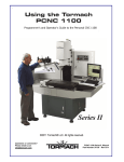
A block diagram of the WSS-lO system is shown in Figure 1. The basi c e lement of the system
is the Wyle Scientific Calculator, Model WS-02. This unit performs all arithmetic functions
and provides th e basi c memory of the system, with three work ing registers and three storage
registers. Basic manual controls and a CRT display of th e registers' contents are also part of
the WS-02.
Programming capability is provided by th e Model PC-01 Punc hed Card Prog ramm er and by the
Model PB-02 Patch Board Programmer. The Mode I PC-01 provides a means of rapidly programming special applications and of building a large libra ry of programs . The Model PB-02
provides program storage of up to 512 program steps for rapid access and execut ion of frequently
used programs. The PB··02 also allows the operator to program instructions which control and/ or
modify the program itself, a feature usually found only in large-scale computers. Programs
can be quickly and easily changed by substituting new program modules or by reprogramming of
the avai lable modules.
SD10-566-1M
WYLE LABORATORIES
Products D ivision· J 33 Center Street. EI Segundo. Ca lif. 90245 • Phone (213)
OREGON
8-425 J I TWX 910-348-6283
The Patch Board Programmer is entirely modular in construction. Both the program storage and
control logic are implemented with plug-in circuit modules.
The Supplemental Memory unit, Model SM-Ol, provides eight additional data storage registers, each with a capacity of 24 decimal digits. Data may be freely transferred between
these registers and the six basic registers of the WS-02. This transfer of information can be
contro lied by either the Punched Card Programmer, Patch Board Programmer or by the operator
via the KB-Ol Peripheral Input Keyboard. Two additional Supplemental Memory Units,
Mode I SM-02, can be added, to provide a tot a I of 24 suppleme nta I re gisters .
The Peripheral Input Keyboard Mode I KB-Ol provides a channe I for the flow of data and
instructions between the various units and also provides additional control keys for manually
addressing the supplemental registers and for manual control of the PB-02.
Plug-in programs are also available which automatically permit the manipulation of negative
numbers. Si gned algebrai c mul tipli cation and division may be carried out without operator
intervention or decision.
I
PATCH BOARD
PUN CHED CARD
PROGRAMMER
PROGRAMMER
MODEL PB-02
MODEL PC-Ol
"
"
ZONE
CALCULATOR
I TRANSFER
1(0 PTI ONA_L_)
MODEL WS-02
KEYBOARD (KB-01)
-.....
...
......
AND I NTERCOUPLER
WS/I C-01
L.--._ _ _ _ _ _ _- - I
SUPPLEMENT AL MEMORY
MODEL SM-01
_-1
t
FI GCRE 1: MODEL WSS-1 0 BLOCK DIAGRAM
SD 10-566-1 M
-------------------------------------------------------------------------------------------,----~
WYLE lABORATORIES
Products Division
e
133 Center Street, El Segundo, Calif. 90245 • Phone (21))
OREGON
::\-4251 /TWX 91 0-34H-62H3
The Supplemental Memory and the Patch Board Programmer are mounted in the pedestal
section of the desk console. The WS-02, the PC-Ol, and the KB-Ol are free-standing units
which stand on the desk, as shown in the photograph. The intercoupler portion of the KB-Ol
is a separate unit located in the desk console.
'
TECHNICAL SPECIFICATIONS
1. CALCULATOR Model WS-02
MEMORY
Six basi c registers. Three (MQ, Entry, and Accumulator)
working registers and three (Rl, R2, and R3) data storage
registers. Each register has a capacity of 24 decima I
digits.
DE CIMAL POI NT
Decimal locations selectable from 21 digits, 3 decimal
places to 3 digits, 21 decimal places, in increments of
3 digits.
OPERATIONS
In the operations list which follows, register designa-
ti ons are read as if preceded by II Contents ofll or If resu Its
appear in ll , as the case may be. For example (ACC) +
(Entry) - ACC is read as, "Contents of Entry are
added to contents of Accumulator and results appear in
Acc umu Iatorl! •
ARITHMETIC OPERATIONS
Add
Sub
Clear & Mult
Mult +
Mult Divide
r
(ACC)
(ACC)
(MQ)
(ACC) + [(MQ)
(ACC) - [(MQ)
[(ACC)
J(ACC)
+ (Entry) x
x
x
/
(Entry)
(Entry)
(Entry)]
(Entry)]
(Entry)]
_
-
ACC
ACC
ACC
ACC
ACC
MQ
MQ
REGISTER ADDRESSING
Six instructions allow TO and FROM addressing of each
of the si x basi c registers. The TO addressing desi gnates
the register receiving data, whether the source is the
keyboard, or the programmers, or another register. The
FROM addressing designates the source of data for
register transfer operations.
"HOUSEKEEPING"
Shift Right, Shift Left
The contents of the register
addressed TO are shifted one
decimal place in the indicated
direction.
SD10-566-1M
WYlE LABORATORIES
Products Division· 133 Center Street. El Segundo. Calif. 90245 • Phone (213)
OREGON
S-425 1ITWX 91 0-348-o?83
j
r-----------------------
Forward Space I
Back Space
The position where the next
data digit is to be entered is
shifted one place ri ght or left.
This allows correction of any
single digit in a 24-digit word.
Transfer
Contents of the register addressed
FROM are copied into the
register addressed TO.
Clear MQ, Clear
Entry, Clear ACC
The contents of the indicated
register are erased and that
register is automati cally
addressed TO.
DATA ENTRY
Eleven instructions (or keys), representing di gits 0 - 9
and decimal point, allow entry of numeric data.
Numbers are entered in the register addressed TO,
starting with the most significant digit. When the
decima I point instruction is received, the di gits
previously entered align on the proper decimal point
location.
Negative results of computation are represented in lOis
complement form. As an example:
- 2 = 999----98.
MODE SELECT SWITCHES
Three slide switches on the WS-02 keyboard allow
manual selection of various operating modes.
1.
ADD ANY REGISTER. In the OFF position, Entry
is added to the ACC when the ADD key is
depressed. In the ON position, the contents of the
register addressed FROM are added to ACC when
ADD key is depressed. Subtraction operates in a
similar fashion.
2.
OVERFLOW LOCK OFF. With overflow lock on,
the machine IIhangs Up" when resu Its of a computation exceed the capacity of a register. With
lock off, the machine loses the most significant
digits but does not hang up.
3.
KEEP REMAINDERS. Remainders are retained after
division and square root operations. See the WS-02
Operation Manual for detai led discussion.
SD 10-566-1 M
~------------------------------.-------------------------------------------------------------I
WYLE LABORATORIES
Products Division • 133 Center Street, FI Segundo. Calif. 90245
e
Phone (213) OR::C;ON S-·4251/TWX 9 [0-348 .. 6283
'(
KEYBOARD/ DISPLAY
II.
The basi c keyboard and display are part of the WS-02.
The keyboard allows manual control of all operations
previously described. The CRT display gives a continuous visual indication of the contents of the six basic
registers and, in conjunction with the Peripheral Input
Keyboard, an "on demand" display of the contents of
supplemental registers.
PERIPHERAL INPUT KEYBOARD Model KB-Ol
KEYBOARD
The KB-Ol provides an auxi I iary manua I keyboard for
addressing supplemental storage registers and for controlling peripherals.
A decimal keyboard is provided for keying-in numerics.
SUPPLEMENTAL REGISTER ADDRESSING
Six keys at the upper left of the KB-Ol keyboard (one
pair for each Supplemental Memory unit) are used, in
conjunction with the numeral keys at the right, to
address supplemental registers. For example, depressing
TO SM A and numeral 1 addresses TO the first register
of the first set of 8. Depressing FROM SM Band
numeral 2 addresses FROM the second register of the
second group of 8.
The DISPLAY key provides an "on command" display
of the supplemental registers. The register of interest
is addressed FROM and the DISPLAY key is depressed.
The contents of the addressed register are displayed in
the Calculator's R3 register as long as the key is held
down. When the key is re leased, the di splay of R3
is resumed. The contents of both registers are unchanged.
SD10-566-1M
WYLE LABORATORIES
Products Division ' 133 Center Street. El Segundo. Calif. 90245 • Phone (21 ~)
OREGON
H-425I/TWX 91 0-34H-62H ~
,-----------------------------------------------------'----------
PROGRAM CONTROL
Two keys a lIow the operator to manua \I y i ni ti ate
programs stored in the PB-02. The keys are labe lied I
II START PB 00-07" a nd II START PB 08-15. II
To start
program Number Three, the operator depresses START
PB 00-07 and numera I 3 . To start Program Number 12.
the operator depresses START PB 08-15 and numera I 4.
The key labelled PB HALT causes the PB-02 to stop
execution and wait for further instructions.
A fter the P B HALT key or after a programmed MAN UAL
ENTRY instruction from the PB-02, the PB RESUME key
is used to restart the PB-02. 1ft he Pun ched Ca rd
Programmer causes the ha It (by a programmed ST OP) ,
it is restarted by the PC RESUME key.
HALT INDICATOR
An indicator on the KB-01 is illuminated by a STOP
instruction from the PC-Ol or by a MANUAL ENTRY
instruction from the PB-02.
III. PUNCHED CARD PROGRAMMER Model PC-Ol
PUNCHED CARDS
The Model PC-Ol reads a standard size I 40-column
punched card. Prescored cards can be prepared with
a simple stylus. Unscored cards can be prepared on
conventional keypunch equipment.
CARD FORMAT
Cards are read a row at a time. Usually only one
column is punched on each row. Thirty-eight of the
columns correspond to the 38 manual keys on the
WS-02 keyboard. One column is punched in all rows,
and this column is used as a "read enable " strobe.
The 40th column is a STOP instruction, which causes
th~ programmer to halt until a resume comma:1d is received,
thus allowing operator intervention in a program.
There are 12 rows per card. Any number of cards may
be taped together for long programs.
SD 10-566-1 M
WVlE LABORATORIES
Products Division· 133 Center Street. EI Segundo. Calif. 90245 • Phone (213) ORFCiON g---1-2) 1iTWX 91 0-3·+:-\-62ID
..-------~------------------------------------------------,
TO
FROM
STEP
J
1
I-
-...
-.
4
;II
I1I-
--
t
NO
AI
I-
1110
~~T
fliT
7
8
9
lu'l
~
AI:C
I I A~C
1[1
~:1
n
~?
R,2
U
R,3
1"_
III
•--•
--
---
!
II P
i
i
i
it.
I
IV
~
••
~,
I.
I~
." v
It
I- -:-
-
I. . .
I ....
MULTIPLE INSTRUCTIONS
I I
!·"'I
CLI:AI
EIIT
1-
It!
I~
I~DI r
rt
II
~
1-
2
;I'(j ,\11
Some instructions use more than one column punched
in a row I as in the following examples.
A complete transfer operation can be punched in
one row:
FROM R1 - TO ACC - TRANSFER
A complete add (or subtract) operati on I in the AD D
ANY REGISTER mode, can be punched in one row:
FROM R2 - ADD
Three bas i c reg isters I' one of wh i ch may be a
storage register I can be addressed in one row:
TO MQ - TO ENTRY - TO Rl
SUPPLEMENTAL REGISTER
ADDRESSING
This is a multiple instruction technique. A simultaneous
FORWARD SPACE and a numeral (1 - 8) addresses TO
one of the registers in the S/"\-Ol's group of 8. BACK
SPACE and a numera I (1 - 8) addresses FROM one
register in the first group of 8" Only the first 8
registers (SM A) can be addressed from the card.
PATCH BOARD
PROGRAMMER CONTROL
Subroutines stored in the PB-02 Patch Board Programmer
can be initiated from the PC-Ol through the use of a
multiple instruction. Only PB-02 Programs 0-7 can
be started by the card programmer. A simultaneous
STOP and a numeral causes the card programmer to
hal t and starts the indicated PB-02 program.
SD10-566-1M
WYLE LABORATORIES
Products Division· 133 Center Street. FI
SC!!,Il!lcio,
Calif. 90245 • Phone ( ~ I ~)
OR}·(;Ol\i
~-~+2.'i I. T\VX 9' ()-.j4~-6283
SPEED
IV.
The PC-01 reads a row at a time and will not read a
new instruction until the previous instruction has been
executed. Maximum read rate is 8 rows per second.
PATCH BOARD PROGRAMMER Model PB-02
PROGRAM STORAGE
Program steps are stored as patch cord connections on
the plug-in patch boards. Up to 16 patch board
modules can be used, each of which allows programming of up to 32 steps, a possible total of 512 program
steps. Each module has 32 inputs whi ch are energized
in sequence by a program counter. Each input can be
patched to one or more of 64 possible output lines,
representing the 64 instructions in the system repertoire.
Each of 16 program modules can be used as a separate
program or severa I 32-step sequences can be I inked to
provide longer programs.
INSTRUCTIONS
WS-02 OPERATION
Thirty-eight instructions directly control the WS-02
Calculator. These instructions correspond to the
manual instruction keys on the WS-02 keyboard or to
the basi c instructions on the punched card.
SUPPLEME NTAL MEMORY ADDRESSI N G
Six instruction I ines are provided to address TO and
FROM supplemental registers. Lines TSA, TSB and
TSC address TO a block of 8 registers, FSA, FSB and
FSC address FROM the blocks. Numeral I ines are
used to se lect a specifi c register. As an example, if
input line 3 is connected to both FSB and numeral 6,
then step 3 addresses FROM the sixth register of
group B.
S D 10-566-1 M
WYLE LABORATORIES
Products Division· 133 Ce nter Street. El Segundo. Ca lif. 90245 • Phone (213)
OREGON
8-4251 I TWX 9 10-348-6283
__ __._---------_._-------------.
.----------------------_._------_.
.
PROGRAM CONTROL
Six instructions are provided to control the PB-02 itself.
These instructions allow programming flexibility comparab Ie to large-sca Ie computers. These instructions
are:
SKIP (SKP)
A SK I P on Step n causes the contents of the FROM
register to be subtracted from (ACC) and / if the
result is negative / the program skips Step n + 1 ,
and executes Step n + 2. If the results are
positive / Step n + 1 is executed. Step n + 1 can
be a bran ch instruction wh i ch starts another
program.
STORE (STR)
A STORE instruction is accompanied by a simultaneous TO instruction (TO MQ, TO ENTRY, TO
A C C, TOR 1 , TO R2 / 0 r TOR 3). A STOR E
instruction on step n causes the step n + 1 to be
executed and the number n + 1 to be stored in a
normally unused portion of the designated register.
Step n + 1 can be used to branch to a subroutine.
Six addresses can be thus stored / one in each of
the registers, without affecting the contents of
the designated register.
RE CALL (RCL)
Accompanied by a FROM instruction (FROM MQ,
FROM ENTRY, FROM ACC, FROM Rl, FROM R2,
or FROM R3). The address (n + 1) placed in the
designated register by a STORE instruction is
transferred to the program counter, and execution
resumes at n + 2.
As an example, Program Pl has STORE and TO MQ
instructions at Step 16. Step 17 transters to
Program P2 and Pl-17 is stored. Program 2 has
RECALL and FROM MQ instructions at Step 20.
P2 is terminated and Pl is resumed at Step 18.
This feature allows a master program to address
subrouti nes.
SD 10-566-1 M
WVLE LABORATORIES
Products Division • 133 Center Street, U SCi~lIndo, Calif. 9()245 .. Phone (].13) OREGON 1'\-4251 ITWX 91 0-341'\-62R3
PB-02 START I (PSI), PB-02 START II (PSII)
Allows unconditional branching to another
program. A step wired to PS 1 and numera I 0 - 7
wi II 'automati ca \I y start execution of the desi gnated
program (0 - 7). A step wired to PS II and numeral
7 wi \I automati ca \I y start the desi gnated
PB-02 program (8 - 15).
o-
MANUAL ENTRY (ME)
The PB-02 program ha Its and the indi cator on the
KB-01 is lit. This allows manual intervention or
data entry. An ME instruction on Step n causes
the PB-02 to ha It on Step n. Depressing the PB
RESUME key causes the program to resume at
Step n + 1 •
STOP (STP)
Indicates the end of a program and causes a halt.
If there is no STOP in Program One the PB-02 will
proceed automatically to execute Program Two,
and so on. This allows continuous programs up to
512 steps long.
SPARES
Twenty spare instruction lines, designated DA, DB,
DC and SP 1 - SP 17 are available to control various
system functions. In the WSS-10 only SP 1 is assigned
a function. Simultaneous STOP and SP 1 will cause
the PB-02 to stop and the PC-01 to start. Th is allows
the PC-01 to use PB-02 programs as subroutines and to
resume operation when the subroutine is completed.
MULTIPLE INSTRUCTIONS
Diode expanders are provided on the program modu les
to expand the inputs. Non-diode expanders allow
several inputs to be tied to a single output line.
In addition to the multiple instruction functions already
mentioned, a \I those mu I ti pie instruction functions
wh ich can be performed with punched cards (such
as FROM Rl - TO MQ - TRANSFER) can also be
programmed on the PB-02.
L__________._______~--~
SD10-566-1M
WYLE LABORATORIES
Products Division • 1::13 Center Street. El Se~l,undo, Calif. 90245
0
Phone (213)
OREGON
8-4251 ITWX 91 O~348-6283
OPERATING MODES
V.
c
A MODE SELECT switch located on the back of the
KB-Ol allows selection of either the RUN mode or the
SINGLE STEP mode. In the RUN mode, programs are
executed automatically at the ma x imum rate. In the
SINGLE STEP mode, one instruction is executed each
time the PB RESUME key on the KB-Ol is depressed.
This mode is useful in program checkout and in
maintenance procedures.
SUPPLEMENTAL MEMORY Model SM-Ol
CAPACITY
The Model SM-Ol provides 8 data storage registers,
each with a capacity of 24 decimal digits.
DECIMAL POINT
Identical to basic registers.
TRANSFER
Data may be transferred between SM registers and the
six basi c registers. Data cannot be transferred between
SM registers directly, only via the six basic registers.
Data cannot be entered directly into SM registers. It
must first be entered in one of the six basic registers
and transferred to an SM register.
ADD, SUB, OPERATIONS
In the ADD ANY REGISTER mode, the data stored in
SM registers can be directly added to or subtracted from
(ACC). The SM register is addressed FROM and an
ADD or SUB instruction executed. The contents of the
SM register are unchanged.
Set by the same switch.
SD 10-566-1 M
WYLE LABORATORIES
Products Division· 133 Center Street. EI Segundo, Calif. 90:>'45 • Phone ( ) 11) OR,
)
I"
I ) ~ .. Il 628 ,
ADDRESSING
The 8 registers contained in SM-01 can be addressed
from the keyboard of the KB-01, from punched cards
via the PC-Ol, and from the PB-02.
VI. OPTIONAL FEATURES
SUPPLEMENTAL MEMORY
Model SM-02
Each SM-02 provides 8 additional data storage registers
identical to those in the SM-Ol. One or two SM-02 I s
can be added for a tota I of 16 or 24 additi ona I data
storage registers.
The SM-02 I s can be addressed by the PB-02 or by the
KB-01 keyboard but not by the PC-Ol.
ZONE TRANSFER
Allows selective transfer of the contents of any register.
Addressing of registers is as previously explained.
However, a numeric command is used with the TRANSFER instruction. Each register is assumed to be composed of 4 zones.
Zone 1: Right hand 6 digits.
Digits 0 - 5
Zone 2: Digits 6 - 11
Zone 3: Digits 12 - 17
Zone 4: Left hand 6 digits.
Digits 18 - 23
The following simultaneous instructions wi II transfer
the block of data shown.
TRANSFER only
All 24 digits
TRANSFER and numeral
Zone 1
TRANSFER and numeral 2
Zone 2
TRANSFER and numeral 3
Zone 3
TRANSFER and numeral 4
Zone 4
Data thus transferred wi II probab Iy not' be properly
located with respect to the decimal point. To speed
this alignment operation a special shifting operation
is part of the Zone Transfer option.
~
~-------------,-----------,
WYlE LABORATORIES
Products Division
SD10-566-1M
- - - - 9
l:n Center Street. EI Sellundo. Calif. 90245
• Phone (21.3)
OREGON
8--4251 ITWX 910-348-6283
_.......
-_.._.. _-.__ ._- _..... _..... _........._._..-_._._ ... -_ .. -•.. _--_....._-_.__ .. ................ _.............. ..... _.,
,
"
---'' -' ',
I
The operator may program the fo lIowi ng mu Iti pie
instructions:
SH IFT RI G HT and numera I
SHIFT LEFT and numeral
(0 - 9)
(0 - 9)
The instruction shifts the contents of the TO register
n decimal places in the indicated direction where n
is the numeral which accompanies the SHIFT instruction.
This eliminates the need for several successive SHIFT
instructions to align data. Numeral 0 causes a shift
of 10 decimal pl~ces in the indicated direction.
VI.
GENERAL SPECIFICATIONS
PACKAGE CONFIGURATION
WS-02
Table top, free-standing
PC-01
Table top, free-standing
KB-01
Table top, free-standing
SM-01
Rack-mounted in desk pedesta I
PB-02
Rack-mounted in desk pedestal
OPTIONS
The options require no additional physical space.
Space is available in the desk to accommodate both
packages.
POWER
115 ± 10 volts, 60 cps. Approximately 215 watts.
FLOOR SPACE
28 inches wide by 50 inches long. Desk is 30 inches
high. WS-02 adds 10-1/4 inches.
SD 10-566-1 M
WYLE LABORATORIES
Products Division ~ 133 Center Street EI Sej~undo. Calif. 90'-.:"1.5 ,\
l'thmc' (:'
______ J
11) (lH !'(iU>i g-PS! ; 1"'>'; X \) 1(),·3~1\.() . ~~n