1
EK-KDASQ-UG-OOI
KDASO-O
USER GUIDE
(SEMI-FINAL REVIEW)
Digital Equipment Corporation
Colorado Springs, Colorado
1st Edition, November 1984
Copyright c 1984
by Digital Equipment Corporation
All Rights Reserved
The material in this manual is for informational purposes and is
subject to change without notice. Digital Equipment Corporation
assumes no responsibility for any errors which may appear in this
manual.
Digital Equipment Corporation makes no representation
that the interconnection of its mass storage products with
products of other manufacturers will not infringe on existing or
future patent rights. Nor do the descriptions contained herein
imply the granting of licenses to make, use, o r l l l equipment
constructed or configured in accordance herewith.
The Digital
Storage Architecture (DSA) and Standard Disk Inte connect (SDI)
mass storage products
manufactured
by
Digital
Equipment
Corporation are designed to work with host computers and OSA and
SOl products designed by Digital Equipment Corporation.
Digital
Equipment Corporation assumes no responsibility or liability if
the host computers, controllers, mass storage servers, tape, or
disk products of another manufacturer are used with these DSA and
SDI products.
Printed in U.S.A.
This equipment generates, uses, and may emit radio frequency
energy.
This equipment has been type tested and found to comply
with the limits for a Class A computing device pursuant to
Subpart J of Part 15 of FCC Rules, which are designed to provide
reasonable protection against such radio frequency interference
when operated in a commercial environment. Operation of this
equipment in a resi~ential area may cause interference in which
case the user at his own expense may be required to take measures
to correct the interference.
The following are trademarks of
Maynard, Massachusetts:
Digital
DEC
DECUS
DIGITAL
Digital Logo
PDP
UNIBUS
VAX
DECnet
DECsystem-IO
DECSYSTEM-20
DECwriter
DIBOL
Edusystem
MASSBUS
RA81
RA60
RA80
HSCSO
Equipment
OMNIBUS
OS/8
PDT
KDASO-Q
RSTS
RSX
VMS
VT
UDASO
lAS
Corporation,
CONTENTS
CHAPTER 1
1.1
1.2
1.3
1.4
1.4.1
1.4.2
1.5
1.5.1
1.5.2
1.6
1.7
1.7.1
1.7.2
1.8
CHAPTER 2
INTRODUCTION
•• •
DISK CONTROLLER • • • • • • • • • • • •
DIGITAL STORAGE ARCHITECTURE (DSA)
• •
MASS STORAGE CONTROL PROTOCOL • • • • • • • • • •
KDA50-Q MODULES • • • • • • • • • • • • • • • • •
The SDI Module • • • • • • • • • • •
• •
The Processor Module • • • • • •
••••• •
KDA50-Q FUNCTIONAL MICROCODE
••••••
QBUS Control Stream • • • • • • • • • • • • • •
Drive Control Stream • • • • • • • • • • • • • •
KDA50-Q SPECIFICATIONS • • • • • • • • • • • • • •
DIGITAL CUSTOMER SERVICE CONTRACT OPTIONS • • • •
Hardware Services • • • • • • • • • • • • • • •
Software Services • • • • • • • • • • • • • • •
RELATED DOCUMENTATION • • • • • • • • • • • • • •
1-1
1-2
1-2
1-3
1-3
1-3
1-4
1-4
1-5
1-6
1-7
1-7
1-8
1-9
INSTALLATION
2.1
INTRODUCTION • • • • • • • • • • • • • • • • • •
2.2
MODULE PREPARATION AND INSTALLATION • • • • • •
I/O Page Address Switches And Jumper..
•
2.2.1
QBUS T;,;d"ling • • • • • • • • • • • •
•••
2.2.2
QBUS Device positions • • • • • • • • • • •
2.2.2.1
2.2.2.2
KDA50-Q Burst Rate Parameter • • • • • • • •
2.2.3
M7164 Intermodule Cable Installation
•••
2.2.4
M7164 Module Installation • • • • • • • • • •
M7165 SDI Cable Installation And Initial M7165
2.2.5
Insertion • • • • • • • • • • • • • • • • • •
M7165 Intermodule Cable Installation • • • • •
2.2.6
2.2.7
Final M7165 Installation • • • • • • • • • • •
2.3
STANDARD INSTALLATION PACKAGE
•••••• • • •
2.3.1
I/O Bulkhead Installation • • • • • • • • • •
2.3.2
Internal SDI Cables • • • • • • • • • • • • •
External SDI Cables • • • • • • • • • • •
2.3.3
2.4
ALTERNATE INSTALLATION PACKAGE • • • • • • • • •
Mounting The Alternate Bulkhead Assembly
2.4.1
Internal SDI Cable Installation • • • • •
2.4.2
External SDI Cable Installation • • • • • • •
2.4.3
FIELD ACCEPTANCE TEST PROCEDURE • • • • • • • •
2.5
Drive-Resident Diagnostics • • • • • • • • • •
2.5.1
Subsystem Diagnostics • • • • • • • • • • • •
2.5.2
PDP-II Subsystem Diagnostics • • • • • • • •
2.5.2.1
VAX Subsystem Diagnostics • • • • • • • • •
2.5.2.2
SYSTEM AND SOFTWARE CONSIDERATIONS
•••
2.6
System Clock Or Timer • • • • • • •
•• •
2.6.1
• 2-1
• 2-4
.~4
•
~8
• 2-8
2-10
2-10
2-11
'.0:..
2-11
2-13
2-13
2-13
2-13
2-14
2-15
2-16
2-16
2-19
2-19
2-20
2-24
2-24
2-25
2-2i
2-2~
2-2~
2.6.2
2.6.3
2.6.4
CHAPTER 3
Error Logs • • • • • • • • • • • • • • • • • •
Drive Numbering • • • • • • • • • • • • • • •
System Performance And Operation • •
• ••
2-27
2-28
2-28
KDA50-Q PROGRAMMER INFORMATION
3.1
KOA50-Q-SPECIFIC PROGRAMMING INFORMATION • • • • • 3-1
1-1
2-1
2-2
2-3
2-4
2-5
2-6
2-7
2-8
2-9
2-10
2-11
2-12
2-13
2-14
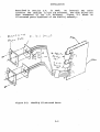
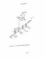
KOA50-Q Disk Subsystem Configuration • • • • • • • 1-1
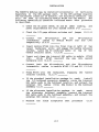
KDA50-Q Illustrated Parts • • • • • • • • • • • • 2-2
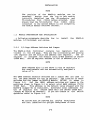
M7164 QBUS Address switch and Jumper Locations • • 2-6
KOA50-Q Switch Setting for Address 172150 (F468
Hex) • • • • • • • • • • • • • • • • • • • • • • • 2-6
Address Selector Switch Operation
• • • • • • 2-;
M7165 Jumper Locations • • • • • • • • • • • • • • 2-7
KDA50-Q Intermodule Flat Ribbon Cables • • • • • 2-11
M7165 SDI Cable Assembly Installation • • • • • 2-12
BAll 2x3 Adapter Plate Installation • • • • • • 2-14
Bulkhead to I/O Panel Attachment • • • • • • • • 2-14
Internal SOl Cable Installation • • • • • • • • 2-15
Grounding Internal SDI Cable(s) [TBD]
• • • • • 2-15
External SOl Cable Installation [TBD]
• • • 2-16
Alternate Bulkhead Assembly • • • • •
• • • 2-18
Diagnostic LED Locations on KDA50-Q Modules
2-21
1-1
2-1
2-2
KDA50-Q Specifications • • •
• • • • 1-6
• •
KDA50-Q Assemblies • • • • • • • • • • • • •
• 2~ 1
LED Error and Symptom Codes
•
•
•
2-21
• • •
erGURES
TABLES
....
5
CHAPTER 1
INTRODUCTION
NOTE
Information that is
designated by: [TBD] •
1.1
currently
unavailable
is
DISK CONTROLLER
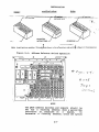
The KDA50~Q is an intelligent controller which
four, 16-bit, RA series disk drives to any CPU
QBUS. Two quad-height modules, the Standard
(SDI) module and the Processor module, make up
interfaces up to
that operates on a
Disk Interconnect
the KDA50-Q.
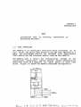
The KDA50-Q uses a radial bus configuration instead of the
conventional daisy-chain (serial) method. Radial configuration
means that there is a separate I/O cable going to each disk
drive. Figure 1-1 shows the KDA50-Q subsystem configuration.
EXTEANAL
eUlI:HEAO
COHIII£CfOA
INTRODUCTION
1.2
DIGITAL STORAGE ARCHITECTURE (DSA)
The KDA50-Q belongs to the family of DSA products which implement
the Standard Disk Interconnect (SDI). DSA defines the operating
rules of mass storage subsystems and how they interface with the
host computer.
Some of the characteristics of DSA are listed
below.
1.3
o
I/O management has been
controller.
moved
from
the
host
o
The host views the disk subsystem as one contiguous
string of sectors known as logical blocks. A logical
block contains 512 bytes of information.
o
The host is not concerned with
cylinder, track, sector, etc.
disk
o
Host and subsystem exchange
Storage Control Protocol.
messages
geometry
use
to
such
the
the
as
Mass
MASS STORAGE CONTROL PROTOCOL
The KDA50-Q Disk Controller is a Mass Storage Control Protocol
(MSCP) device.
MSCP is a communication protocol used with
intelligent
mass
storage
controllers.
MSCP
hides
device-dependent requirements, such as disk geometry and error
recovery strategies, from the host.
It thus enables several
different device drivers to be replaced by one class driver.
To request an I/O operation, the host constructs an MSCP message
and sends it to the controller. The MSCP message contains the
drive address, the function to be performed, the starting logical
block number (sector), and the amount of data requested. The
message does not contain drive geometry information because MSCP
hides device dependant requirements. When the subsystem receives
the request, it performs all drive management and data movement,
as
well
as
any necessary recovery, independently.
Upon
completion, the subsystem sends the host an MSCP response message
giving status information. This flow differs from conventional
subsystems, in which host computer resources would be used to
control the drive. One recovery technique is called revectoring,
when the KDA50-Q accesses a replacement sector instead of the
original sector previously found to be in error. A sector is
marked as bad, and replaced via a cooperative process between the
host software and the KDA50-Q.
1-2
INTRODUCTION
1.4
KDASO-O MODULES
The following paragraphs describe the hardware on
module and the processor module.
1.4.1
both
the
SOl
The SOl Module
The SDI module (M716S) is the the communication interface between
the KOASO-O processor module and the disk drives. Some of the
circuitry and functions of the SDI module are listed below.
o
Contains a 32K byte high speed buffer that is used
during
data
transfers.
The
buffer
allows
controller-to-drive tranfers to occur at a higher rate
than
controller-to-host
transfers
which
improves
performance by minimizing missed disk revolutions due to
a buffer full condition.
o
Converts the KDASO-O buffer format
format (serial) and vice-versa.
o
Generates the real-time Error Correction Code (ECC).
This code has a correction capability of up to 8 lO-bit
error bursts per block (sector).
o
Implements the real-time and electrical interface to the
SOl, including error detection on the SOl, and RAM.
1.4.2
(parallel)
to
SDI
The Processor Module
The processor module (M7164)
is the control portion of the
KDASO-Q.
Some of the circuitry and functions of the processor
module are listed below.
o
Performs all KOASO-O interaction with the QBUS via two
regfsters; the Initializing and polling (IP) register
and the Status/address (SA) register. A switch pack is
used to set the I/O page register address.
o
Reports microcode detected errors through four LEOs on
the processor module and four LEOs on the SOl module.
The error code reported indicates the module to replace.
o
Also located on the processor module is
a
dual
microprocessor.
It
is
made
up
of two 12-bit
microprogram sequencers which share a common 16-bit ALU.
1-3
INTRODUCTION
The combination of the sequencers and the shared ALU
creates a dual microprocessor capable of executing two
independent, interleaved microprograms (from Read Only
Memory) at the same time.
One of the sequencers
controls the KDASO-Q to host interaction and the other
controls the KDA50-Q to disk drive interaction.
For
greater efficiency, one sequencer fetches an instruction
while the other executes an instruction.
1.5
KDA50-Q FUNCTIONAL MICROCODE
The functional microcode can be divided into two functional flows
or streams. The QBUS control stream which manages the controller
to host interface and the drive control stream which manages the
controller to disk drive interface.
1.5.1
QBUS Control Stream
Some of the functions that the QBUS Control Stream
listed below.
performs
are
o
Tracks to the appropriate handling routine in the
microcode when the host has a command to send to the
KDA50-Q or the KDASO-Q has a response to send to the
host.
o
Exchanges information packets with the host in memory.
o
Validates each packet from the host.
o
Constructs the KDASO-Q response packets for transmission
to the host.
o
Analyzes the drive packets and
listed below.
performs
the
functions
o
Decodes the logical block number (LBN) to ,cylinder,
group, track, and sector information.
o
Optimizes
commands.
o
Allocates data buffer space.
seek
selection
1-4
from
the
outstanding
INTRODUCTION
o
Computes and
transfer.
stores
parameters
for
each
sector
o
Performs packet error detection.
~
Performs memory mapping for mapped requests.
o
Transfers data between the host and internal memory
(including
automatic
support
for
block mode
memories).
o
Performs ECC error correction.
o
Polls the
command.
o
Performs initialization.
o
Initiates Drive Control Stream packet executions.
1.5.2
command
queue
at
the
completion
of
each
Drive Control Stream
Some of the functions that the Drive Control Stream performs
listed below.
are
o
Monitors ATTENTION from the
drives.
When
drive
attention has been detected, the Drive Control Stream
gets the drive status, compares it with the previous
status, and takes the appropriate action.
o
Constructs and sends packets to the disk drives.
The
packets may be the result of a host request (read,
write, replace, etc.) or in response to a
drive
attention condition.
o
Receives and validates packets from the drives.
o
Monitors the drive status flags from the QBUS Control
Stream.
The
drive
status
flags
are used for
communication between the QBUS control stream and the
Drive Control Stream.
o
Performs tasks as required by the drive
Some of these tasks' are listed below.
,1-5
status
flags.
INTRODUCTION
1.6
o
Initiates read, write, seek, and head select packets
to the drive.
o
Reads and verifies the block (sector) header.
o
Performs data transfers between internal RAM and the
disk drive.
o
Updates drive status and buffer-use flags.
o
Performs data error analysis and recovery.
o
Performs bad block revectoring.
KDA50-Q SPECIFICATIONS
The KDA50-Q Disk Controller Specifications are described in Table
1-1.
Table 1-1:
KDA50-Q Specifications
Characteristics
Specifications
Physical components
KDA50-Q processor module (M7164)
KDA50-Q SOl module (M7165)
50-pin flat cable assembly
40-pin flat cable assembly
SOl cable assembly
I/O bulkhead assemblies
Power consumption
67.9 Watts nominal
Heat dissipation
Approximately 238.6 Btu/hour
Electrical voltage
and
current
requirementsf
13.5 Amps at +5 Volts, 30 milliAmps
at +12 Volts
QBUS Loading
3.0 AC
(total)
Operating
temperature range
10- C to 40- C (50- F to 104- F)
with a temperature gradient of 20C/hour (36- F/hour)
1-6
/
0.5
DC
standard loads
INTRODUCTION
Table 1-1 (cont.)
"'1aracteristics
Specifications
Operating relative
humidity range
10%
to
90%
with a wet bulb
temperature of 2S- C (S2- F) and a
minimum dew point of 2- C (36- F)
Operating
.Ldnge
Sea level to 2400 meters (SOOO ft).
Derate
the
maximum
allowable
operating
temperature
by
1.SC/IOOO meters (1- F/IOOO feet)
for
operation above sea level
altitude
"njunting
restrictions
Mounts in two quad-height QBUS SPC
slots in the following mounting
boxes:
BAll-S or -N
BA23 (rackmounted) with H3490
Bulkhead
requirements
Two 2x3" cutouts for BAll-S or -N,
Two 3x2" standard cutouts for H3490
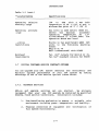
1.7
DIGITAL CUSTOMER SERVICE CONTRACT OPTIONS
You can upgrade your CPU system smoothly and efficiently and
maintain optimum performance of your new system by taking
advantage of one of the service options listed below.
1.7.1
Hardware Services
Add-on and upgrade services get you started.
We strongly
recommend that your new CPU upgrade be installed by qualified
DIGITAL field service technicians. Installation includes:
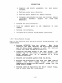
1.
Pre-installation evaluation to ensure a suitable site
environment including power, temperature, and humidity.
2.
Physical connection of equipment
full system functionality.
1-7
and
verification
of
INTRODUCTION
Maintenance services keep you going. Once your upgrade has been
installed by DIGITAL field service, the entire upgraded system
will be eligible for coverage by one of the following DIGITAL
comprehensive service contracts.
1.
DECservice - A comprehensive on-site service provides
committed response times, continous effort until the
problem is solved, a program of preventive maintenance,
installation of the latest engineering changes, and
automatic escalation for complex problems.
2.
Basic Service - An economical full service coverage
provides priority status, second only to DECservice
calls, and you get the preventive maintenance on-site
services listed above.
For less comprehensive but equally reliable service you can
choose Per Call Service, Carry-In Service or DECmailer Service.
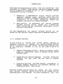
1.7.2
Software Services
If your need is to analyze your current system, develop or
implement software, or upgrade your existing system, DIGITAL
offers a service to meet your needs. The following services will
be of particular interest to you as you plan to add on or
upgrade.
1/ . Computer Performance Service - Helps you develop growth
plans by identifying add-on or upgrade options before
problems begin.
2.
System Start-up Service Packages Provides fixed-cost
training
for your staff and one year of support
services.
3.
Consulting Services - Provides software programming or
project manager expertise on a resident, per-call, or
fixed-price basis. Your choice.
Whichever DIGITAL service option you select, you will receive
high quality, reliable service from one of the largest service
organizations in the industry. For more information J
call your
1-8
INTRODUCTION
local DIGITAL field service office.
1.8
RELATED DOCUMENTATION
DIGITAL customers
manuals.
may
order
the
following
KDA50-Q
o
KDA50-Q SERVICE MANUAL (EK-KDA5Q-SV)
o
KDA50-Q FIELD MAINTENANCE PRINT SET (MP-01423)
Employees:
related
The User Guide and Service Manual may be
ordered directly from Publication and
Circulation Services, 10 Forbes Road,
Nothboro, Massachusetts 01532 (RCS Code:
NR12, Mail Code: NR03/W3).
The Field Maintenance Print Set can be
ordered directly from the Software
Distribution Center, 444 Whitney Street,
Northboro, Massachusetts 01532 (RCS
Code: MSDC, Mail Code: NR02-l/J6).
Non-~mployees:
The above documents can be ordered
directly from Digital Equipment
Corporation, P.O. Box CS2008, Nashua,
New Hampshire 03061, or by calling toll
free: 800-258-1710.
Outside the united States, consult local DIGITAL offices.
1-9
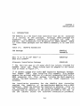
CHAPTER 2
INSTALLATION
2.1
INTRODUCTION
The KDASO-Q is a two board disk controller that can be installed
in a variety of CPU packages.
Although these packages are
different, the KDA50-Q installation procedure for them
is
similar. The differences will be called out where needed. Table
2-1 lists these packages and the KDA50-Q assembly to be used with
them.
Table 2-1:
KDA50-Q Assemblies
CPO Package
KDASO-O
Assembly
BAll -S or -N (5 1/4" BOX)* or
BA23 with H3490**
KDA50-QA
Alternate Installation Package
KDA50-QB
* The· BAll box uses an I/O panel which has cutouts intended for
MASSBUS cable use. These cutouts must be adapted to 2x3 cutout
size as shown in Figure 2-7.
** If needed, please also order BA23 Expansion Rackmount Package,
Part Number [TBD], when installing this assembly. This package
permits the optional addition of a second rackmounted BA23 with a
QBUS expansion kit. This package includes the BA23 expansion
cabinet, the BA23 rackmount kit, and the H3490 expansion I/O
bulkhead.
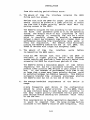
The installation procedure for the KDA50-Q Disk Controller
requires the insertion of two quad-height modules into a QBUS
backplane. These two modules are inserted in adjacent slots so
the intermodule cables can be connected between them. An I/O
bulkhead must be installed in the cutout provided at the rear of
the CPU cabinet unless the alternate installation procedure,
2-1
INSTALLATION
described in section 2.4, is used.
An internal SOl cable
connects the modules to the I/O bulkhead. The disk drives are
then connected to the I/O bulkhead.
Figure 2-1 shows an
illustrated parts breakdown of the KOASO-Q assembly.
Figure 2-1:
KOASO-O Illustrated Parts
2-2
INSTALLATION
The KOA50-Q modules may be installed horizontally or vertically
depending on the CPU package used. If the CPU package requires
the horizontal insertion of modules, the following checklist may
still be used by considering module M7l64 the top module. The
following installation checklist indicates where each procedure
is described.
o
Check the DC power needs, AC and DC QBUS loading,
panel requirements for your system (Table 1-1)
o
Check the 'I/O page address switches and
o
Connect
the
40-conductor
and
the
50-conductor
intermodule
cables to module M7l64 (J2) and (J4)
respectively (2.2.3)
o
Insert module M7l64 into the first (top or left) of two
vacant backplane slots and engage the handle retainer
latches. Leave the 50 conductor cable on top of the
handle retainer latch.
(2.2.4)
o
Insert and clamp the internal SOl cable to module M7l65
(J4).
Slide
M7165 one-half the way into second
backplane slot (2.2.5)
o
Connect both the 40-conductor and the 50-conductor
intermodule cables to module M7l65 (J3 and Jl) (2.2.6)
o
Press M7165 into the backplane,
retainer latches. (2.2.7)
o
If the standard installation package is used:
install
the I/O bulkhead' connector assembly, route the internal
SOl cable ends to the bulkhead location, and connect the
external SDI cables (from DSA disks) to the bulkhead
assembly (2.3)
o
If the alternate installation package is used:
mount
the alternate bulkhead assembly, connect the internal
SOl cable ends to the bulkhead assembly, and connect the
external SDI cables (2.4)
o
Perform
the
field
acceptance
2-3
jumper
engaging
test
the
procedure
and
(2.2.1)
handle
(2.5)
INSTALLATION
NOTE
The position of the KDA50-Q modules can be
reversed.
Ensure that the top or left module
initially installed has the 40-conductor and
50-conductor flat ribbon cables attached. Also
ensure that the 50-conductor flat ribbon cable
connected to the second module is not crimped by
the module handle retainer latches.
2.2
MODULE PREPARATION AND INSTALLATION
__ e following paragraphs describe
how
modules, I/O bulkhead, and cables.
2.2.1
to
install
the
KDA50-Q
I/O Page Address Switches And Jumper
The KDA50-Q Disk Controller contains two registers that are
visible in the I/O page. They are the initializing and polling
(IP) register and the status and address (SA) register.
The IP
register is ~ssigned the default octal Q-BUS address of 172150
(F468 Hex). The SA register address is the IP address plus 2.
NOTE
QBUS address bits 13 and above in the IP register
are unadjustable and are automatically assigned a
value of 1.
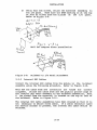
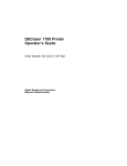
The QBUS address selector switches and a jumper (WI) are used to
set the QBUS address for the IP register. The location of these
switches and the jumper on KDA50-Q module (M7l64)
is shown in
Figure 2-2.
Set the QBUS address switches and jumper to the
positions sho~n in Figure 2-3 to select octal QBUS address 172150
(F468 Hex).
This address is the default value shipped with the
KDA50-Q (jumper WI is installed). Alternate octal addresses for
the IP register are: 160334 (EODC Hex) and 160340 (EOEO Hex).
(Jumper WI should be removed). If you are unsure of the switch
operation refer to Figure 2-4.
NOTE
W2 and W3 must be removed for Q22/CD backplanes
and left installed for Q22/Q22 backplanes on both
2-4
INSTALLATION
modules M7l64 (refer to
(refer to Figure 2-5).
Figure
,2-5
2-2)
and
M7165
INSTALLATION
,
.1
~BV.s
RPbA.r.s$
Gl'tS
,lJ~Ls
'\
i1
1'1 1'3 1'2.
\71
7
OC.TAL.
c.ode.
aUJ~RY
,.... c..OI>E"
,I
I,
II 'r II
'\ \. 1'\
QDRS.O' ti
5Wd-c.h
Sefiit\Gt
4
l
I(
\'
I
-.!!!!!II
II
'0
2.
0
f
~l.
r
~
9
I
;--
0
o
"
0 I
~
4
3
10 f
o (J
Of
S/O-~
OfT OFt. OfF ~tJ Ctl orr: DfJ OFF
.1
'. OA)e5
f:1L.W-- ,. 1'5
Figure 2-2:
0
o
S-
Sl S2. S3 S'I SS Sl. Sl SI S"
I~ orr ow
I
Z.
RLWIfYS"
aeV-D5
M7164 QBUS Address switch and Jumper Locations
LeDS
~
1I11""\\II~
HL-_J~4~_
so P,,,,,)
L
M7/~L{
11)'1"" 7 9q tt-
{II III
f,,
ill ;~,::
/Q :lL..-_~i'n!o--".
_--P:J
"'1-
j ~::~
)WI,~~J
Figure 2-3:
KDA50-Q Switch Setting for Address 172150 (F468 Hex)
2-6
INSTALLATION
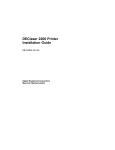
modified rocker:
rocker:
slider:
I :
l-v
on position
red band here
on position
,
Ie
Note: In each picture, switches 1 through..' are shown in the off position, and switch ~ is shown in the on position.
Figure 2-4:
Address Selector Switch Operation
/r~ -1t~)
Jt.,;-" r~ (
NOTE
The oaus address switches and jumpers should be
set for a floating address when a second DSA
controller is installed on
a
system.
To
determine a floating address, check the system
2-7
INSTALLATION
configuration and QBUS addresses of all devices
octal
already
installed.
Common
floating
addresses are 160340 (EOEO Hex) and 160330 (EOD8
Hex).
In past disk products, a vector addr~ss was also physically
selectable.
This is not true with the KDA50-Q Disk Controller.
A typical vector address of 154 (octal) will be supplied to the
KDA50-Q by the software.
2.2.2
QBUS Tuning
Sometimes a QBUS system will experience data late or reduced
performance conditions that can be remedied by tuning the QBUS.
This process involves changing the relative positions of the
Direct Memory Access (DMA) devices on the bus, or making use of
other product features. The device electrically nearest the host
processor has the highest priority; the device farthest away from
the host processor has the lowest priority.
2.2.2.1
QBUS Device Positions -
should
usually
be
placed
Non-DMA interfaces in a QBUS
electrically nearest to the host processor since they do not
signficantly affect the performance level of DMA devices.
The proper positioning of
several considerations.
1.
DMA
devices
on
the
QBUS
The instantaneous bandwidth requirements of
or interface.
the
involves
device
Faster raw bandwidth devices typically require a higher
priority, though this higher priority requirement- can be
offset by buffering in the interface which reduces the
instantaneous bandwidth requirements from the interface.
Interfaces with little buffering may require that the'
instantaneous bandwidth match or exceed the effective
bandwidth for the device.
While the KDA50-Q interfaces to some very fast disk
devices, it is well buffered internally (which results
in a relatively low instantaneous bandwidth requirement)
and operates dependably at the very end of the QBUS
(lowest priority). The KDA50-Q will wait very long
periods of time to gain access to the bus, and proceed
2-8
INSTALLATION
from this waiting period without error.
2.
The amount of time the
during each bus access.
interface
occupies
the
OBUS
Devices that hold the QBUS for longer periods of time
should usually be placed at a lower priority, to reduce
the time that a higher priority device must wait for
gaining access to the OBUS.
The KDASO-Q occupies the bus according to the setting of
the Burst rate parameter given to it by the operating
system. The default value of four long-words (8 word
transfers) results in occupying the bus for a value
which is carefully chosen to provide a compromise
between a small bus occupancy time and a higher level of
performance resulting from transferring more words in
every bus acquisition.
The default value encourages
placing the KDASO-Q towards the end of the OBUS, but
ahead of devices with longer bus occupancy times.
3.
The amount of time
the
interface
re-requesting the QBUS again.
waits
before
Since all DMA devices must wait until the OBUS is
available, a higher priority device which requests
access rapidly may preclude a lower priority device from
accessing the OBUS for significant periods of time.
The KDASO-Q leaves a reasonable amount of time before
requesting the bus for a successive transfer, and this
permits lower priority DMA devices to gain access to the
bus.
In the interest of performance, this time is not
so large that a great many lower priority devices could
be satisfied between two KDASO-Q requests. This KDASO-Q
successive transfer time allowance encourages placing
the KDASO-Q near but not at the end of the bus.
4.
The average bandwidth
usage.
requirements
of
the
device
in
A more frequently used device in the configuration
should be given a higher priority. In the QBUS, there
is some intrinsic delay in each bus cycle according to
how many higher priority interfaces the bus grant must
pass through before reaching the interface which wants
to use the bus.
This consideration is highly application dependent, but
it would be expected that the large storage devices
connected to the KDASO-Q would be used frequently. This
2-9
INSTALLATION
would encourage placing
the end of the QBUS.
the KDA50-Q further away from
Overall, the recommendation is to place the KDA50-Q ahead of such
devices as the RC25 and RQDX, and behind other DMA devices.
However, do not worry if physical configuration details force you
to place the KDA50-Q at the very end of the bus (assuming that
bus grants are passed to the KDA50-Q).
2.2.2.2
KDA50-Q Burst Rate Parameter -
The KDA50-Q burst rate parameter is a value settable by host
software that indicates how many long-words (32 bits) the KDA50-Q
will attempt to transfer when it accesses the QBUS. The default
for this parameter is four, but can range from one to eight.
The overall system efficiency increases by increasing the KDA50-Q
burst parameter to a number greater than one. However, data late
conditions (on other devices) may become increasingly likely as
the parameter is increased.
The default value of four on other devices is chosen
large majority of system configurations.
2.2.3
to
suit
a
M7164 Intermodule Cable Installation
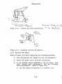
The KDA50-Q modules must be interconnected by two 4 inch long
flat ribbon cables as shown in Figure 2-6. The outer cable is a
50-conductor flat ribbon cable that connects M7164 (J4) to M7165
(Jl).
The inner cable is a 40-conductor flat ribbon cable that
connects M7l64 (J2) to M7165 (J3). Install the two cables on
module M7164 first.
2-10
INSTALLATION
L40 c.,tlll4c..t~r
&
ri~i\
~b(t.·
"fi
.1':) c:,,J .. d~(
~+- riU~~
CQLlt..
Figure 2-6:
2.2.4
KDASO-Q Intermodule Flat Ribbon Cables
M7164 Module Installation
At this point, module M7164 should have two intermodule cables
attached to it and the I/O page address switches and jumper
should be properly set.
Ensure that previously inserted
grouping in the backplane.
modules
form
a
continuous
Insert M7l64 into the first of two vacant backplane slots.
slot should be the top or left backplane slot of the pair.
This
Press M7l64 into the backplane and engage the handle retainer
latches.
Ensure the 50-conductor flat ribbon cable is on top of
the handle retainer latch.
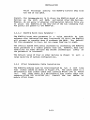
2.2.5
M7l65 SDI Cable Installation And Initial M7165 Insertion
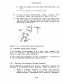
Insert plug P4 of the internal SDI cable assembly into connector
J4 on KDASO-O module M716S as shown in Figure 2-7. Slide the
cable retainer over connector J4 until the connector protrudes
through the plastic cutout. The cable retainer should lock the
SOl cable in place.
2-11
INSTALLATION
~
....
Figure 2-7:
-~---
M7l65 SDI Cable Assembly Installation
Slide M7165 approximately one-half the
slot.
2-12
way
into
the
backplane
INSTALLATION
2.2.6
M7l65 Intermodule Cable Installation
T~stall the 40-conductor flat ribbon cable on module
M7165 (J3)
and the 50-conductor flat ribbon cable on M7165 (Jl) as shown in
Figure 2-6.
2.2.7
Final M7l65 Installation
~~ess
M7165 into the backplane and engage the handle retainer
latches.
Ensure the 50-conductor flat ribbon cable is on top of
the handle retainer latch. Also ensure both modules are now
ti~cure and none of the cables are crimped by the latch handles.
2.3
STANDARD INSTALLATION PACKAGE
Use the following
assembly.
2.3.1
procedures
when
installing
the
KOA50-QA
I/O Bulkhead Installation
An I/O bulkhead connector must be installed on the I/O panel at
the rear of the CPU cabinet. The connectors are designed to fit
in standard Digital Equipment Corporation 2x3 cutouts (used on
most of the newer systems). If the system is installed in a BAll
box, an adapter plate must be installed to convert "the existing
I/O panel cutout to standard 2x3 cutout size.
If an I/O panel is not available,
Cable Installation section 2.4.
refer
to
the
Alternate
SOl
Each bulkhead connector will accept two disk
connections.
Install both bulkheads and connect the internal SOl cables even
if some parts will initially be unused. After the bulkheads have
been installed, route the SOl cables to the bulkhead location.
Use the following procedure to install the I/O bulkhead connector
assembly if an I/O panel is present.
1)
If the BAll box is used, a 2x3 adapter plate must be
used to change the existing I/O panel cutout to 2x3
cutout size. The adapter plate attaches on the inside
of the I/O panel. Refer to Figure 2-8.
2-13
INSTALLATION
2)
Using four sem screws, attach the bulkhead assembly to
the I/O panel. Make sure the EVEN marking is at the top
or left as viewed from the outside of the I/O panel.
Refer to Figure 2-9.
CA
n -5 r - I)
(J
AJ~\+o r
Pff'J..1e..
~Ic fa r .. 1 ( £~ h
Figure 2-9:
2.3.2
ria
t)
Bulkhead to I/O Panel Attachment
Internal SDI Cables
Install the internal SDI cables from the module to the bulkhead
assembly using the following procedure. Refer to Figure 2-10.
Note how the cable ends and connectors are keyed for correct
alignment. ~ttach the cable ends and the pigtail ground clips of
the internal SOl cable assembly to the bulkhead assemblies. Port
o (as viewed from the exterior) is located on the top or left of
the bulkhead. Refer to Figure 2-11.
The internal SOl cable assemblies have been created so that it is
not necessary to secure extra cable. If a cable retractor (used
for service access) is present, the internal SOl cable should be
attached.
2-14
INSTALLATION
-.~
I;
)
(.
t (:3
S'1~r I; d) .
1\ '"
Figure 2-10:
Internal SOl Cable Installation
Figure 2-11:
Grounding Internal SOl Cable(s)
2.3.3
1'\ 11'l
Y'
External SOl Cables
Refer to Figure 2-12 while completing the following procedure.
1)
Plug the external SOl cables into the I/O bulkhead(s).
2)
Secure the cables using the screw connections.
3)
If the external cables connected to the I/O panel have
their natural bend horizontally, use the following
securing procedure. Refer to Figure 2-12.
a)
Run the cables horizontally to a vertical rail.
2-15
INSTALLATION
b)
Twist the cables and route them vertically down
rail.
c)
Tie the cables to the vertical rail.
4)
If the external cables have
their
natural
bend
vertically) secure the cables ~t the base of the cab.
5)
Any cables that go to drives that are in'the same cab as
the CPU should have any extra cable length secured so
that it will not interfere with the normal operation and
servicing of the drive.
Figure 2-12:
2.4
the
External SOl Cable Installation
ALTERNATE INSTALLATION PACKAGE
If an I/O panel is not present or if a very long internal SOl
cable is required, the ~ KOASO-Q alternate installation package
should be used (Part Number KDASO-QB).
If 2x3 cutouts are available, use the installation
in the I/O Bulkhead Installation section above.
2.4.1
instructions
Mounting The Alternate Bulkhead Assembly
Use the following procedure only if it is impossible to mount the
bulkhead to an I/O panel using a KOASO-QA. Refer to Figure 2-13.
1.
Select a suitable location on either rear vertical
cabinet rail where the alternate I/O bulkhead can be
mounted without interfering with existing equipment.
2-16
INSTALLATION
Choose the lowest available location in the cabinet.
2.
Push on the four u-nuts to align them with the holes
the vertical rail bracket.
3.
Select the best angle and mount the bulkhead shield
terminator onto the vertical rail bracket with two
Phillips head sems (10-32 x 1/2 inch).
4.
Mount the vertical rail bracket onto the vertical
cabinet rail with the four Phillips head sems (10-32 x
1/2 inch).
5.
Assemble the bulkhead assembly as shown in Figure 2-13.
2-17
in
INSTALLATION
Figure 2-13:
Alternate Bulkhead Assembly
2-18
INSTALLATION
2.4.2
Internal SOl Cable Installation
Install the internal SOl cables from the module to the bulkhead
assembly using the following procedure. Refer to Figure 2-10.
Note how the cable ends and connectors are keyed for correct
"alignment.
"",d,"."
1.
Connect the internal SOl cables to the bulkhead. Port 0
(as viewed from the exterior) is located on the top or
left of the bulkhead.
2.
Secure the internal
retainer bracket.
3.
Secure any extra internal SOl cable(s)
vertical rail.
2.4.3
SOl
cables
to
the
to
inside
the
cable
cabinet
External SOl Cable Installation
The external SOl cables must be grounded to the I/O bulkhead by
mounting the shield terminators with screws. Use the following
procedure to install the cables. Refer to Figure 2-12.
1.
Plug the first SOl cable into the bottom or right I/O
bulkhead connector and secure the cable using the screw
connections.
2.
Install an SOl cable for each disk drive,
I/O bulkhead connector 3 and moving to O.
starting
at
NOTE
One useful practice is to connect drive 0 to
KOASO-Q port 0 and drive 1 to KOASO-Q port 1,
etc. However, it actually does not matter which
drive connects to which KDASO-Q port.
The
KOASO-Q treats each port equally and obtains the
unit number for each drive from that drive.
3.
Install the drive end of the SOl cables into the drive
I/O bulkhead connectors as described in the disk drive
user guide.
2-19
INSTALLATION
In most cases, the provlslons already provided with the box
should be used to secure the exterior SDI cables. If provisions
have not been provided, the exterior cables should be secured to
the backframe using cable tie(s).
2.5
FIELD ACCEPTANCE TEST PROCEDURE
The field acceptance and test
Subsystem has three parts.
KDASO-Q
Disk
procedure
for
Controller
the
KDA50-Q
resident
Disk
1.
Run the
test.
diagnostic
2.
Run the disk drive field acceptance test
disk drive user guide.
3.
After each subsystem device has been tested separately,
the
KDA50-Q
host-resident diagnostics are run to
complete the third part of this procedure.
found
in
the
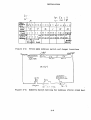
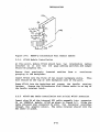
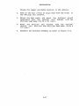
The KDA50-Q-resident diagnostics are initiated when power is
applied to the KDA50-Q Disk Controller. The CPU should be halted
during this test. The four LED indicators on each KDA50-Q module
should display a cycling pattern in the LEDs. Refer to the third
comment following Table 2-2. The cycling pattern in the LEDs
signifies the completion of a successful KDA50-Q diagnostic test.
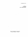
Figure 2-14 shows the location of the four LEDs on each KDASO-Q
module.
2-20
/'1 71
~
L(
I~'-_---Jn~___ f\-. ___n_.__- i
i
M7J bS"--_ _ _-"'II\...._ _ _ _\~---n.---.
Figure 2-14:
Diagnostic LEO Locations on KOASO-Q Modules
If the KOASO-Q LEOs do not display the cycling pattern after
power is applied, look up the LED code in Table 2-2 to locate the
problem.
Table 2-2:
LEO Error and Symptom Codes
M7l64
LEOs*
842 1
M7165
LEDs·
8 4 2 1
Error Symptoms
Most
Likely
Failure
0 0 0 1
x x x x
Hex 1; undefined
Undefined
0 0 1 0
0 0 0 0
Hex 2; microcode stuck in
init step 2
or
M7164
software
0 0 1 1
0 0 0 0
Hex 3; microcode stuck in
init step 3
**
2-21
INSTALLATION
Table 2-2 (cont.)
M7l64
LEDs*
8 4 2 1
M7165
LEDs*
8 4 2 1
Error Symptoms
Most
Likely
Failure
~----------------------------------------------------- ----------
0 1 0 0
0 0
B
L
0 1 0 I
N
o
o
0
0 0 0
K
Hex 4: microcode stuck in
step
init
4 or QBUS
timeout error
or
M7l64
host
inactive
Hex 4/5: test complete
Normal display for
operating KDA50-Q
No problem
x x x x
0 1 1 0
Hex 6: undefined
Undefined
x x x x
0 1 1 1
x x x x
x x x x
0 1 1 1
Hex 7: undefined
Undefined
1 0 0 0
0 0 0 0
Hex 8; wrap bit 14 set in
SA register
M7164
or
software
1 0 0 1
0 0 0 0
1 0 0 1
Hex 9: board one error
M7l64
0 0 0 0
1 0 1 0
1 0 1 0
0 0 0 0
1 0 1 0
Hex A: board two error
M7l65
1 0 1 1
x x x x
x x x x
1 0 1 1
Hex
Undefined
x x x x
1 1 0 0
1 1 0 0
Hex Ci Timeout error,
check error code in SA
register
(Refer
to
KDASO-Q Service Manual)
1 1 0 1
x x x x
x x x x
1 1 0 1
Hex
RAM parity error
M7165
1 1 1 0
x x x x
x x x x
1 1 1 0
Hex E: ROM parity error
M7164
1 1 1 1
1 1 1 1
Hex Fi sequencer error
M7164
Cycling
pattern
Cycling
pattern
None
No problem
***
0 1 1 0
x x x x
Bi
Di
undefined
2-22
Many
causes
INSTALLATION
Table 2-2 (cont.)
M7165
LEOs·
8 4 2 1
M7164
LEOs·
842 1
Most
Likely
Failure
Error Symptoms
••• During a cycling pattern, the LEOs flash one at a time
starting at the LSb and progressing through the MSb. These LEDs
begin flashing on the M7l64 module, then progress to the M7I65
module. However, the pattern is executed very fast so it looks
like all the LEOs are flashing at the same time. The flash goes
on and off for approximately 1/4 second and then repeats at
about a 4 second rate. The LEOs normally cycle while the KDA50-Q
is waiting for the host to start the initialization process. At
that time, it responds to the initialization and the cycling
pattern stops. This normally occurs in about four seconds,
if
the system software is prepared to e?tablish a connection with
the KDA50-Q.
Note: 1
=
LED ON
o=
x
LED OFF
= May
be ON or OFF
When two codes are given for the same error, both
same failure.
2.5.1
indicate
the
Drive-Resident Diagnostics
Each disk drive should be tested separately by running the
drive-resident
diagnostics.
The procedure for running the
resident diagnostics is found in the installation chapter of the
disk drive user guide. Perform the drive field acceptance tests
found in the installation chapter and then go to Paragraph 2.5.2
for the subsystem diagnostic procedures.
2.5.2
Subsystem Diagnostics
The subsystem diagnostic procedures for the KDASO-Q controller
differ when they are used on a PDP-II CPU or a VAX CPU. The
following paragraphs cover the PDP-II diagnostics first and then
the VAX diagnostics.
NOTE
If the diagnostic program reports
to the KDA50-0 Service Manual.
2-24
errors,
refer
INSTALLATION
CSR ADDRESS OF CONTROLLER (0) 172150 ?
NOTE:
CSR=IP.
VECTOR (0) 154 ?
BR LEVEL (D) 5 ?
NOTE:
The KDA50-Q ignores this question and
automatically reassigns the appropriate BR LEVEL
of 4.
DRIVE NUMBER (D) 0 ?
Sample CZUDI hardware prompts:
CHANGE HW (L) Y ?
t UNITS (D) 1 ?
UNIT 0
CSR ADDRESS OF CONTROLLER (0) 172150 ?
DRIVE NUMBER (D) 0 ?
EXERCISE ON CUSTOMER DATA AREA (L) N ?
Sample CZUDH software prompts:
CHANGE SW (L) Y ?
ENTER MANUAL INTERVENTION MODE IN TEST 2 (L) N ?
Sample CZUDI software prompts:
CHANGE SW (L) Y ?
ENTER MANUAL INTERVENTION MODE FOR SPECIAL DIAGNOSIS (L) N ?
ERROR LIMIT (D) 32 ?
READ TRANSFER LIMIT IN MEGABYTES - 0 FOR NO LIMIT (D) 0 ?
SUPRESS PRINTING SOFT ERRORS (L) Y ?
DO INITIAL WRITE ON START (L) Y ?
ENABLE ERROR LOG (L) N ?
2-26
INSTALLATION
2.5.2.2
o
VAX Subsystem Diagnostics EHRAD (KDA50-Q Disk Drive Formatter)
EHRAD is not a diagnostic.
specifically instructed to.
o
Do
not
run
it
unless
EHRAA (KDA50-Q Basic Subsystem Diagnostic)
EHRAA consists of the following three tests:
o
Test 1
BUS Addressing test
o
Test 2
Disk-Resident Diagnostic Test
o
Test 3
Disk Functional Test
o
EHRAB (Disk Exerciser Test)
o
EHRAC (Subsystem Exerciser Test)
This program tests the read and write ability of any SDI
type disk drive from a KDA50-Q, and will display
differences in the read and write data to the operator.
2.6
2.6.1
SYSTEM AND SOFTWARE CONSIDERATIONS
System Clock Or Timer
Some aspects of both diagnostic and/or functional usage of a
KDA50-Q depend upon the ability of the host processor to time-out
- on an operation. It is recommended that clock interrupts be
enabled.
Check host processor documentation for appropriate
instructions.
2.6.2
Error Logs
The KDA50-0 has the capability to return information to the
operating system for inclusion into an error log. These entries
may include specific information on the operation of the KDA50-Q,
its
attached drives, or other parts of the system (host
processor, memory, software, etc.) which may be important in
diagnosing the source of possible problems. It is recommended
that error logging be enabled in your operating system to take
advantage of such information.
Consult your operating system
2-27
INSTALLATION
documentation for approrpriate information
error logs.
on
the
enabling
of
Some reports contained in the error log may represent changes in
the
configuration
or
operation of your system that are
informational in nature, and thus may not represent the occurance
of an error condition. Examples of this may be:
2.6.3
o
completion of the initialization
port driver and the KDASO-Q
sequence
between
the
o
attention messages pertaining to the availability of a
disk drive (which may be the result of changing a
drive's unit number)
Drive Numbering
DSA/SDI drives that can be connected to the KDA50-Q can usually
be given a unit number ranging from 0 to 254. Some operating
systems do not support this entire range of unit numbers,
sometimes only supporting the range 0 to 7. Consult operating
system documentation for appropriate capability, and
drive
documentation for how to specify unit numbers.
The unit numbers assigned to drives attached to a KDASO-Q do not
imply any priority, or other special property; all drives are
treated equally by the KDA50-Q. The only requirement on unit
number assignments is to avoid duplicating a unit number on two
different drives, which could lead to confusion by an application
or user.
The KDA50-Q will not permit a drive, to be accessed if
its unit number~ duplicates another drive'S number while the
second drive is also attached. This situation may be corrected
by changing either (or both) of the duplicating numbers.
Unit numbers can usually be easily changed at the drive, although
this is recommended only when the intended drive is not online
(not mounted by the operating system) to the KDA50-Q.
2.6.4
System Performance And Operation
Consult the QBUS sections in this Chapter for information
pertaining to KDA50-Q features and placement which may bear on
performance or operation of your system.
2-28