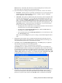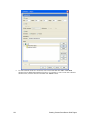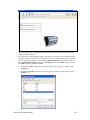
1
i.LON® Vision 2.0
User’s Guide
®
078-0422-01A
Echelon, LON, LONWORKS, LonTalk, Neuron, LONMARK, 3120,
3150, LNS, LonMaker, and the Echelon logo are trademarks
of Echelon Corporation registered in the United States and
other countries. LonPoint and LonSupport are trademarks of
Echelon Corporation.
Other brand and product names are trademarks or
registered trademarks of their respective holders.
Neuron Chips, LonPoint Modules, and other OEM Products
were not designed for use in equipment or systems which
involve danger to human health or safety or a risk of property
damage and Echelon assumes no responsibility or liability for
use of the Neuron Chips or LonPoint Modules in such
applications.
Parts manufactured by vendors other than Echelon and
referenced in this document have been described for
illustrative purposes only, and may not have been tested by
Echelon. It is the responsibility of the customer to determine
the suitability of these parts for each application.
ECHELON MAKES NO REPRESENTATION, WARRANTY, OR
CONDITION OF ANY KIND, EXPRESS, IMPLIED, STATUTORY, OR
OTHERWISE OR IN ANY COMMUNICATION WITH YOU,
INCLUDING, BUT NOT LIMITED TO, ANY IMPLIED WARRANTIES OF
MERCHANTABILITY, SATISFACTORY QUALITY, FITNESS FOR ANY
PARTICULAR PURPOSE, NONINFRINGEMENT, AND THEIR
EQUIVALENTS.
No part of this publication may be reproduced, stored in a
retrieval system, or transmitted, in any form or by any means,
electronic, mechanical, photocopying, recording, or
otherwise, without the prior written permission of Echelon
Corporation.
Printed in the United States of America.
Copyright ©1997–2009 by Echelon Corporation.
Echelon Corporation
www.echelon.com
ii
Preface
Table of Contents
Preface .................................................................................................... vi
Purpose ..........................................................................................................vii
Audience.........................................................................................................vii
Hardware Requirements.................................................................................vii
i.LON SmartServer 2.0 Documentation..........................................................vii
Content ..........................................................................................................viii
For More Information and Technical Support................................................. ix
Using the i.LON Vision 2.0 Online Help Files .......................................... ix
Viewing the i.LON Vision 2.0 ReadMe..................................................... ix
Using Technical Support.......................................................................... ix
1
Introduction ....................................................................................... 1
Introduction ...................................................................................................... 2
What’s New in i.LON Vision 2.0 ................................................................ 2
i.LON Vision 2.0 Compatibility with i.LON Vision 1.0................................ 2
Installing Echelon i.LON Vision 2.0 Software ........................................... 3
2
Quick-Start Exercise ......................................................................... 9
Introduction .................................................................................................... 10
Step 1: Creating a Web Site Connection ................................................ 10
Step 2: Creating a Custom SmartServer Web Page .............................. 12
Step 3: Adding i.LON Vision Objects ...................................................... 14
Step 4: Linking a Custom Web Page to the SmartServer Home
Page........................................................................................................ 24
3
Creating Custom SmartServer 2.0 Web Pages............................. 29
Introduction .................................................................................................... 30
Configuring i.LON Vision 2.0 Preferences..................................................... 30
Upgrading Custom Web Pages to SmartServer 2.0 Pages .......................... 32
Upgrading SmartServer 1.0 Web Pages to SmartServer 2.0 Pages...... 32
Upgrading e3 Web Pages to SmartServer 2.0 Pages ............................ 32
Adding i.LON Vision Objects to your Custom Web Pages............................ 33
Adding Data Point Read/Write Objects................................................... 34
Show Value ...................................................................................... 37
Text Field .......................................................................................... 43
Text Area .......................................................................................... 49
Combo Box....................................................................................... 55
Image Swapper ................................................................................ 61
Radio Buttons ................................................................................... 68
Select Box ........................................................................................ 73
Check Box ........................................................................................ 77
SVG Object....................................................................................... 82
Custom JavaScript Object ................................................................ 89
Adding Application Objects ................................................................... 107
Data Point View .............................................................................. 108
Data Log View ................................................................................ 113
Scheduler........................................................................................ 115
Alarm Notifier.................................................................................. 118
Changing the Page Title ....................................................................... 120
Setting the Poll Rate ............................................................................. 120
Adding Link Objects .............................................................................. 121
Adding a Navigation System to your Web Design....................................... 124
Creating a Home Page ......................................................................... 124
i.LON Vision 2.0 User’s Guide
iii
Manually Creating the Home Page ................................................ 124
Using an Echelon Frameset Template to Create the Home
Page ............................................................................................... 128
Designing the Menu Frame................................................................... 129
Opening the Menu.htm File ............................................................ 129
Adding a Menu Bar to the Menu Frame ......................................... 130
Adding a Page Title to the Menu Frame......................................... 137
Adding a Message Box to the Menu Frame ................................... 138
Adding Menu Buttons to the Menu Frame...................................... 140
Adding Graphics to the Menu Frame ............................................. 141
Designing the Sidebar Frame ............................................................... 143
Opening the Sidebar.htm File......................................................... 144
Adding a Tree to the Sidebar Frame .............................................. 145
Adding a Vertical Menu to the Sidebar Frame ............................... 151
Designing the Copyright Frame ............................................................ 153
Opening the Copyright.htm File...................................................... 153
Changing the Copyright Message .................................................. 154
4
Advanced SmartServer 2.0 Web Page Topics ............................ 157
Data Point Status and Priority Icons............................................................ 158
Using Data Point Priorities........................................................................... 159
Priority Level Example .......................................................................... 159
When To Use Priority Levels ................................................................ 161
Scenario 1: No Priorities Used with Internal Devices and
i.LON Vision Objects........................................................................ 161
Scenario 2: Priorities Used with Internal Devices and
i.LON Vision Objects ...................................................................... 162
Scenario 3: Priorities Used with Internal Devices,
i.LON Vision Objects, and External Devices .................................. 162
Using Data Point Substitution Tags............................................................. 163
Adding Placeholder Values to a Data Point Name ............................... 164
Specifying Substitution Tags................................................................. 166
Using the NLS Text Object .......................................................................... 172
Opening SmartServer Applications from Custom Web Pages................................ 183
Linking to a Configuration Web Page from a Navigation Object .......... 183
Linking to a Configuration Web Page from a Link Object ..................... 187
Copying and Pasting Objects in i.LON Vision ............................................. 189
Copying i.LON Vision Objects............................................................... 189
Adding i.LON Vision Objects to a Layer................................................ 190
Adding i.LON Vision Objects to a Table................................................ 192
Adding Images to a Layer ..................................................................... 193
Adding a New Image to a Layer Object.......................................... 193
Moving an Existing Image to a Layer Object.................................. 195
Securing Custom SmartServer Web Pages ................................................ 199
Using an External Web Publishing Tool ...................................................... 199
Troubleshooting Custom Web Page Designs ............................................. 199
5
i.LON Vision 2.0 API ...................................................................... 201
Introduction .................................................................................................. 202
Custom Web Page Requirements ............................................................... 202
General Object Requirements ..................................................................... 202
Object-Specific Properties ........................................................................... 204
Show Value Properties ......................................................................... 204
Text Field Properties ............................................................................. 204
Text Area Properties ............................................................................. 204
Combo Box Properties.......................................................................... 205
iv
Preface
Image Swapper Properties ................................................................... 205
Radio Buttons Properties ...................................................................... 205
Select Box Properties ........................................................................... 205
Check Box Properties ........................................................................... 206
Custom JavaScript Properties .............................................................. 206
Data Point View Properties ................................................................... 206
Data Log View Properties ..................................................................... 206
Scheduler Properties............................................................................. 207
Alarm Notifier Properties....................................................................... 208
i.LON Vision 2.0 User’s Guide
v
Preface
i.LON Vision 2.0 is a standalone Web publishing tool that you can use to create
custom Web pages for monitoring and controlling the data points on your
SmartServer 2.0.
vi
Preface
Purpose
This document describes how to create custom Web pages for monitoring and controlling LONWORKS
networks and other control networks.
Audience
This guide is intended for system designers and integrators with an understanding of control networks.
Hardware Requirements
Requirements for the running the i.LON Vision 2.0 software are listed below:
•
Microsoft® Windows Vista® or Microsoft Windows® XP. Echelon recommends that you install
the latest service pack available from Microsoft for your version of Windows.
•
Intel® Pentium® III 600MHz processor or faster, and meeting the minimum Windows
requirements for the selected version of Windows (Pentium III 1.3 GHz or faster if running Echelon
Enterprise Services 2.0).
•
50 to 530 megabytes (MB) free hard-disk space, plus the minimum Windows requirements for the
selected version of Windows.
o
The i.LON Vision 2.0 software requires 44 MB of free space.
o
If you install Echelon Enterprise Services 2.0 from the i.LON SmartServer 2.0 DVD, you
need an additional 270 MB of free space. Echelon Enterprise Services 2.0 is required for
monitoring and controlling the data points of external devices with custom SmartServer 2.0
Web pages.
If you are running Echelon Enterprise Services 2.0, LNS Turbo Editions (3.25) or later must
be installed on the LNS Server computer. See the Echelon Enterprise Services 2.0 User’s
Guide for more information on installing Echelon Enterprise Services 2.0 and LNS Server
Service Pack 5 from the i.LON SmartServer 2.0 DVD.
o
If you install Adobe® Reader 9.1 from the i.LON SmartServer 2.0 DVD, you need an
additional 204 MB of free space. You need Adobe Reader or another PDF viewer to view the
i.LON Vision 2.0 documentation.
Note: Windows Vista testing for i.LON Vision 2.0 has been performed on computers that
have a minimum of 2 GB of RAM. For complete Windows Vista requirements, refer to
www.microsoft.com/windows/windows-vista/get/system-requirements.aspx. You can use
Microsoft’s Vista Upgrade Advisor to determine upgrade requirements for a particular
computer. To download this tool, go to the Microsoft Web site at
www.microsoft.com/windows/windows-vista/get/upgrade-advisor.aspx.
•
DVD-ROM drive.
•
1024x768 or higher-resolution display with at least 256 colors.
•
Mouse or compatible pointing device.
•
If you are running Echelon Enterprise Services 2.0 on your computer, LNS Turbo Editions (3.25)
or later is required.
•
Microsoft Internet Explorer 7 or higher or Mozilla Firefox.
i.LON SmartServer 2.0 Documentation
The documentation for the SmartServer is provided as Adobe Acrobat PDF files and online help files.
The PDF file for this document is installed in the Echelon i.LON Vision SmartServer 2.0 program
i.LON Vision 2.0 User’s Guide
vii
folder when you install the i.LON Vision 2.0 software. You can also download the latest SmartServer
documentation, including the latest version of this guide, from Echelon’s Website at
www.echelon.com/support/documentation/manuals/cis.
This user’s guide, the online help files, and the following documents comprise the SmartServer
documentation suite:
•
i.LON SmartServer 2.0 User’s Guide. Describes how to configure the SmartServer and use its
applications to manage control networks.
•
Echelon Enterprise Services 2.0 User’s Guide. Describes how to use the LNS Proxy Web service
to manage LNS networks, and how to use the i.LON AdminServer to rapidly and automatically
deploy and install LONWORKS networks.
•
i.LON SmartServer 2.0 Power Line Repeating Network Management Guide. Describes how to
install a PL-20 repeating network and how to use the SmartServer to prepare, maintain, monitor
and control, and connect the network.
•
i.LON SmartServer 2.0 Programmer’s Reference. Describes how to configure the SmartServer
using XML files and SOAP calls. This allows you to create your own applications that you can
use to configure the i.LON.
•
i.LON SmartServer 2.0 Programming Tools User’s Guide. Describes how to write custom
embedded applications called Freely Programmable Modules (FPMs) and deploy them on the
SmartServer. FPMs let you implement custom functionality and tailor the SmartServer to meet
your needs.
•
i.LON SmartServer 2.0 Hardware Guide. Describes how to assemble, mount, and wire the
SmartServer hardware.
•
i.LON SmartServer 2.0 Quick Start Guide. Contains all the information you will need to connect
the SmartServer hardware, install the i.LON SmartServer 2.0 software, and configure the
SmartServer using the SmartServer configuration Web pages.
•
IP-852 Channel User’s Guide. Describes how to configure an IP-852 channel with the Echelon
LONWORKS®/IP Configuration Server. You will need this information if you plan to use the
i.LON as an IP-852 router.
Content
This guide includes the following content:
viii
•
Introduction: Introduces i.LON Vision 2.0, summarizes the new features in i.LON Vision 2.0,
describes the compatibility of i.LON Vision 2.0 with i.LON Vision 1.0, and describes how to
install the i.LON Vision 2.0 software.
•
Quick-Start Exercise. Describes how to create a simple custom SmartServer 2.0 Web page that
you can use to control and monitor a digital relay output on the SmartServer.
•
Creating Custom SmartServer 2.0 Web Pages. Describes how to create simple custom
SmartServer 2.0 Web pages and more complex Web designs that include a navigation system. It
describes how to upgrade existing custom Web pages to SmartServer 2.0 Web pages, add i.LON
Vision objects to your custom Web pages, and design a navigation system for your Web design.
•
Advanced SmartServer 2.0 Web Page Topics. Describes how to use data point priorities, how to
use data point substitution tags, translate custom SmartServer 2.0 Web pages into different
languages, and open the SmartServer’s built-in applications from custom SmartServer 2.0 Web
pages. Describes how to secure and troubleshoot custom SmartServer 2.0 Web pages.
•
i.LON Vision 2.0 API. Describes the programming interface for i.LON Vision objects so that you
can use any Web publishing tool to edit custom SmartServer 2.0 Web pages.
Preface
For More Information and Technical Support
If you need help using i.LON Vision 2.0, you can use the online help files, view the i.LON Vision 2.0
ReadMe, or read the i.LON Vision 2.0 documentation. If none of these sources, answer your
questions, you can contact technical support if you have purchased support services from Echelon or
an Echelon support partner.
Using the i.LON Vision 2.0 Online Help Files
If you need more information on how to use a particular i.LON Vision 2.0 dialog, you can click Help
in the bottom right-hand corner of the dialog to open a new window with context-sensitive help for that
dialog.
Viewing the i.LON Vision 2.0 ReadMe
The i.LON Vision 2.0 ReadMe provides descriptions of known problems, if any, and their
workarounds. To view the i.LON Vision 2.0 ReadMe, click Start, point to Programs, point to
Echelon i.LON Vision SmartServer 2.0, and then select i.LON Vision SmartServer 2.0 ReadMe
First. You can also find additional information about the i.LON SmartServer 2.0 online at
www.echelon.com/ilon.
Using Technical Support
If you have technical questions that are not answered by this document, the i.LON Vision 2.0 online
help, or the i.LON Vision 2.0 ReadMe document, you can contact technical support. Free e-mail
support is available or you can purchase phone support from Echelon or an Echelon support partner.
See www.echelon.com/support for more information on Echelon support and training services.
You can also view free online training or enroll in training classes at Echelon or an Echelon training
center to learn more about developing devices. You can find additional information about device
development training at www.echelon.com/training.
i.LON Vision 2.0 User’s Guide
ix
You can obtain technical support via phone, fax, or e-mail from your closest Echelon support center.
The contact information is as follows (check www.echelon.com/support for updates to this
information):
x
Region
The Americas
Languages Supported
English
Japanese
Contact Information
Echelon Corporation
Attn. Customer Support
550 Meridian Avenue
San Jose, CA 95126
Phone (toll-free):
1.800-258-4LON (258-4566)
Phone: +1.408-938-5200
Fax: +1.408-790-3801
[email protected]
Europe
English
German
French
Italian
Echelon Europe Ltd.
Suite 12
Building 6
Croxley Green Business Park
Hatters Lane
Watford
Hertfordshire WD18 8YH
United Kingdom
Phone: +44 (0)1923 430200
Fax: +44 (0)1923 430300
[email protected]
Japan
Japanese
Echelon Japan
Holland Hills Mori Tower, 18F
5-11.2 Toranomon, Minato-ku
Tokyo 105-0001
Japan
Phone: +81.3-5733-3320
Fax: +81.3-5733-3321
[email protected]
China
Chinese
English
Echelon Greater China
Rm. 1007-1008, IBM Tower
Pacific Century Place
2A Gong Ti Bei Lu
Chaoyang District
Beijing 100027, China
Phone: +86-10-6539-3750
Fax: +86-10-6539-3754
[email protected]
Other Regions
English
Japanese
Phone: +1.408-938-5200
Fax: +1.408-328-3801
[email protected]
Preface
1
Introduction
This chapter introduces i.LON Vision 2.0, summarizes the new features in i.LON
Vision 2.0, describes the compatibility of i.LON Vision 2.0 with i.LON Vision 1.0,
and describes how to install the i.LON Vision 2.0 software.
i.LON Vision 2.0 User’s Guide
1
Introduction
You can use i.LON Vision 2.0 to create custom Web pages for monitoring and controlling the data
points on your SmartServer 2.0—without any knowledge of HTML, JavaScript, or Web programming.
The i.LON Vision 2.0 toolkit provides many objects that you can use to read and write values to data
points, including basic read/write objects; SVG objects (for example, sliders, gauges, and
thermometers); application objects that expose some of the SmartServer’s built-in applications to your
end users; and a custom JavaScript object for implementing your own custom objects.
You can use i.LON Vision 2.0 to create new custom Web pages, and edit existing custom Web pages
previously built with i.LON Vision 1.0 and Adobe Contribute CS3/CS4. i.LON Vision 2.0 is a
standalone Web publishing tool so you do not have to purchase Contribute or any other Web
publishing software to use it. Custom Web pages created with i.LON Vision 2.0 support both Internet
Explorer and FireFox Web browsers.
i.LON Vision 2.0 features quicker Web page creation as you can switch between the edit and publish
views of your Web pages without long delays. This means that you can create or edit a custom Web
page and instantly see the results when you publish it. i.LON Vision 2.0 functions similarly to i.LON
Vision 1.0. You create or edit a custom Web page, insert objects and edit their properties, design the
custom Web page, and then publish it. Adding a navigation system with frameset, menu, and sidebar
objects is also the same.
What’s New in i.LON Vision 2.0
The i.LON Vision objects available to you in i.LON Vision 2.0 are the same. The SVG object
(formerly referred to as the Slider object) does include several new sliders and gauges. In addition, the
SVG object includes a new option for setting a specific range, such as 68 to 74° Fahrenheit (20 to
23.3° Celsius), which is displayed on the SVG object.
The property dialogs in i.LON Vision 2.0 include faster data point selection and local presets. To
select data points, you now expand the network/channel/device/functional block objects in a familiar
SmartServer tree view, and then select the desired target data point. All i.LON Vision read/write
objects now include an option for creating local presets, which are presets that can be used for that
object instance. This enables you to use a field in a structured data point for any i.LON Vision object,
now including the image swapper, check box, and show value objects.
The API for the i.LON Vision objects are now documented so that you can use any Web publishing
tool to create and edit SmartServer 2.0 Web pages.
i.LON Vision 2.0 Compatibility with i.LON Vision 1.0
The following summarizes i.LON Vision 2.0 compatibility with i.LON Vision 1.0.
2
•
You can install both i.LON Vision 2.0 and i.LON Vision 1.0 on the same computer. In this case,
you use i.LON Vision 2.0 to create custom SmartServer 2.0 Web pages, and you use i.LON Vision
1.0 with Contribute CS3/CS4 to create custom Web pages for the SmartServer 1.0 and i.LON e3
Internet Server. The tools remain independent, so installing i.LON Vision 2.0 does not add any of
the new features described in this section to i.LON Vision 1.0.
•
You can use i.LON Vision 2.0 to automatically upgrade all existing custom Web pages to the
SmartServer 2.0 format. This includes all custom SmartServer 1.0 Web pages previously built
with i.LON Vision 1.0 and Contribute CS3/CS4, and custom i.LON e3 Internet Server Web pages
previously built with i.LON Vision 1.0 and Contribute 3.0/3.1/CS3/CS4. See Upgrading Custom
Web Pages to SmartServer 2.0 Pages in Chapter 3 for more information.
•
You can use i.LON Vision 2.0 to create or edit custom SmartServer 2.0 Web pages stored on a
SmartServer 2.0. You cannot use i.LON Vision 2.0 to create or edit custom SmartServer 1.0 Web
pages stored on a SmartServer 1.0. Conversely, you cannot use the i.LON Vision 1.0 tool to
create or edit custom SmartServer 2.0 Web pages stored on a SmartServer 2.0.
Creating Custom SmartServer Web Pages
•
You can use Adobe Dreamweaver CS4, Contribute CS3 or CS4 (without i.LON Vision 1.0), or
any other Web publishing tool to manually create and edit custom SmartServer 2.0 Web pages.
Chapter 5 includes the API for the i.LON Vision objects so that you can use any Web publishing
tool to create and edit SmartServer 2.0 Web pages.
Note: A SmartServer 2.0 refers to a SmartServer running the Release 4.03 firmware (or higher).
SmartServer 1.0 refers to a SmartServer running the Release 4, 4.01, or 4.02 firmware. You can
use the Setup – System Info Web page to view the version of the current firmware on your
SmartServer. To open this Web page, right-click the SmartServer icon in the navigation pane on
the left side of the SmartServer Web interface, point to Setup, and then click System Info on the
shortcut menu.
Installing Echelon i.LON Vision 2.0 Software
To install the i.LON Vision 2.0 software, follow these steps:
1.
Insert the i.LON SmartServer 2.0 DVD into your DVD-ROM drive. If your computer does not
have a DVD-ROM, insert the i.LON SmartServer 2.0 DVD on a network-accessible computer that
has a DVD-ROM and copy the files on the DVD to a shared network drive. You can then copy
the i.LON SmartServer 2.0 files from the shared drive to your computer and install the various
i.LON SmartServer 2.0 products.
2.
If the i.LON SmartServer 2.0 setup application does not launch immediately, click Start on the
taskbar and then and click Run. Browse to the setup.exe file in the root directory of the i.LON
SmartServer 2.0 DVD and click Open. The Echelon i.LON SmartServer 2.0 main menu opens.
3.
Click Install Products. The Install Products dialog opens.
i.LON Vision 2.0 User’s Guide
3
4
4.
Click Echelon i.LON Vision SmartServer 2.0. The i.LON Vision 2.0 Software installer opens.
5.
Read the information on the Welcome window and click Next. The License Agreement window
appears.
Creating Custom SmartServer Web Pages
6.
Read the license agreement (you can read a printed version of the license agreement in Appendix
E of the i.LON SmartServer 2.0 User’s Guide). If you agree with the terms, click Accept the
Terms and then click Next. The Customer Information window appears.
7.
Enter your name and company name in the appropriate fields. The name and company may be
entered automatically based on the user currently logged on and whether other Echelon products
are installed on your computer. Click Next. The Destination Folder window opens.
i.LON Vision 2.0 User’s Guide
5
8.
By default, the i.LON Vision 2.0 software will be installed in the
C:\LonWorks\iLON\iLonVision directory, or it will be installed in the C:\Program
Files\LonWorks\iLON\iLonVision directory if you have not previously installed any Echelon or
LONMARK products. You can click Change to select a different destination folder. Click Next.
The Ready to Install window opens.
9.
Click Install to begin the i.LON Vision 2.0 software installation.
10. After the i.LON Vision 2.0 software has been installed, a window appears stating that the
installation has been completed successfully.
6
Creating Custom SmartServer Web Pages
11. Click Finish, and then read the i.LON Vision 2.0 ReadMe document.
i.LON Vision 2.0 User’s Guide
7
8
Creating Custom SmartServer Web Pages
2
Quick-Start Exercise
This chapter describes how to create a simple custom SmartServer 2.0 Web page that
you can use to control and monitor a digital relay output on the SmartServer.
i.LON Vision 2.0 User’s Guide
9
Introduction
This chapter provides a quick-start exercise that shows you how to create a simple custom SmartServer
2.0 Web page. In this quick-start exercise, you will create a Web page that controls and monitors the
first digital relay output on the SmartServer (Digital Output 1). The Web page will include two
objects: an image swapper switch object that you can click to enable or disable Digital Output 1 by
writing to its nviClaValue_1 input data point, and an image swapper lamp object that indicates
whether Digital Output 1 is ON or OFF by reading its nvoClaValueFB_1 data point.
After you have completed this quick-start exercise, read Chapter 3, Creating Custom SmartServer 2.0
Web Pages, to learn how to create more complex Web designs. For example, you can create multiple
custom Web pages that are linked via a menu or a navigation pane, and you can use a number of
different objects to monitor and control your data points.
To create the simple custom SmartServer 2.0 Web page, you perform the following steps:
1.
2.
3.
4.
Create a Website connection between i.LON Vision 2.0 and your SmartServer.
Create a new custom SmartServer 2.0 Web page.
Add i.LON Vision objects to your custom SmartServer 2.0 Web page.
Link your custom SmartServer 2.0 Web page to your SmartServer home page.
Step 1: Creating a Web Site Connection
To create a Web site connection between i.LON Vision 2.0 and your SmartServer, follow these steps:
1.
10
Start i.LON Vision 2.0. To do this, click Start, point to Programs, point to Echelon i.LON
Vision SmartServer 2.0, and then click i.LON Vision SmartServer 2.0. i.LON Vision 2.0
opens.
Quick-Start Exercise
2.
In the language box at the bottom left-hand corner, select the language to be used for the
SmartServer Web interface. You can use i.LON Vision 2.0 in English (the default), German, and
French.
3.
Click Manage Connections in the Sites pane on the left side, or click File and then click Site
Manager. The Site Manager dialog opens.
4.
Click New Site. The Edit Site dialog opens.
5.
Enter the following information:
i.LON Address
Enter the IPv4 address of your SmartServer.
Comment
Optionally, enter a description of the SmartServer, or any other text.
HTTP Port
If you are using an HTTP port on the SmartServer for serving SOAP and
WebDAV requests other than the default (port 80), enter the port.
HTTP User
Enter the user name for logging in to your SmartServer via HTTP. The
default user name is ilon.
HTTP Password
Enter the password for logging in to your SmartServer via HTTP. The
default user name is ilon.
i.LON Vision 2.0 User’s Guide
11
6.
FTP Port
If you are using an FTP port on the SmartServer other than the default
(port 21), enter the port.
FTP User
Enter the user name for logging in to your SmartServer via FTP. The
default user name is ilon.
FTP Password
Enter the password for logging in to your SmartServer via FTP. The
default user name is ilon.
Click OK twice. A link with the IP address of your SmartServer is added to the Sites pane.
Step 2: Creating a Custom SmartServer Web Page
To create a new custom SmartServer 2.0 Web page, follow these steps:
1.
12
Click the New button on the Editor toolbar (
Select Folder dialog opens.
), or click File and then click New Page. The
Quick-Start Exercise
2.
Expand the SmartServer icon, expand and click the user folder (you must create the new folder in
the root/web/user directory on the SmartServer flash disk), and then click the New Folder icon to
create the directory for your custom SmartServer 2.0 Web page.
3.
The New Folder dialog opens. Enter the name for the folder where all the custom SmartServer
2.0 Web pages for a given Web design will be stored. For this example, enter Custom. Click
OK.
i.LON Vision 2.0 User’s Guide
13
4.
Click the custom SmartServer 2.0 Web page folder you created in step 3, and then click OK.
5.
Click Publish on the Editor toolbar (
Publish. The Publish As dialog opens.
6.
In the File Name property, enter the name of the .htm file (one word with no spaces). For this
example, enter CustomWebPage. Click OK.
7.
Optionally, you change the title of your custom SmartServer 2.0 Web page and the poll rate of the
objects in your custom Web page following these steps:
), click the Browse tab, or click File and then click
a.
Click Format and then click Page Title Properties. The Page Properties dialog opens.
b.
In the Page Title box, enter a descriptive page title and then click OK.
c.
In the Poll Interval box, set how frequently (in seconds) that all the i.LON Vision objects in
your custom Web page poll the SmartServer’s internal data server for data point updates. If
you do not specify a poll rate, the default poll rate is 1 second.
Note: You can set the frequency in which individual i.LON Vision objects poll their
specified data points by setting the Max Age property in the object’s respective properties
dialog.
d.
8.
Click OK.
You can begin editing your custom SmartServer 2.0 Web page by adding i.LON Vision objects to
it, as described in the next section.
Step 3: Adding i.LON Vision Objects
To add i.LON Vision objects to your custom SmartServer 2.0 Web page, follow these steps:
14
Quick-Start Exercise
1.
Click Edit on the Editor toolbar (
2.
Click Insert and then select Image Swapper.
3.
The Image Swapper dialog opens.
i.LON Vision 2.0 User’s Guide
) or click the Layout tab.
15
4.
16
Select the nviClaValue_1 data point of the first relay output on the SmartServer (Digital Output
1) following these steps:
a.
In the Data Point property, click Select. The Select Data Points dialog opens.
b.
Verify that the Show Hidden Items check box is selected. By default, all of the
SmartServer’s functional blocks are hidden in the SmartServer tree.
c.
Expand the network, expand the channel on which SmartServer is attached, expand the
SmartServer internal automated systems device, expand the Digital Output 1 functional
block, expand the nviClaValue_1 data point, and then select the state field (Net/LON/iLON
App/Digital Output 1/nviClaValue_1.state by default). Click OK.
Quick-Start Exercise
d.
The Name and Format boxes of the Data Point property in the Image Swapper dialog are
updated to reflect the selected data point.
i.LON Vision 2.0 User’s Guide
17
5.
Verify that the Switchable check box is selected. This enables the switch graphic to be changed
when clicked. Clicking the switch writes an updated value to the data point, and it changes the
switch graphic displayed based on the new data point value.
6.
Create local presets to be used by the image swapper object for the Net/LON/iLON App/Digital
Output 1/nviClaValue_1.state data point. To do this, follow these steps:
a.
Select the Use Local Presets check box, and then click Edit. The Local Presets dialog
opens.
b.
Create local ON and OFF presets for the data point.
•
•
18
In the Preset box, enter “ON”, in the Value box enter “1”, and then click Save.
In the Preset box, enter “OFF”, in the Value box enter “0”, and then click Save.
Quick-Start Exercise
c.
7.
Click OK to return to the Image Swapper dialog.
Select the image to represent the nviClaValue_1.state data point when it is OFF following these
steps:
a.
In the Images list in the lower part of the Image Swapper dialog, select OFF and then click
Select. The Select File dialog opens.
b.
Browse to the Desktop\C:\LonWorks\iLON\iLonVision\graphics\switch folder, click a
graphic of a switch in the OFF position, and then click OK. This graphic will be displayed
when the data point is set to OFF and the Digital Output is disabled. Because the Switchable
check box is selected, you can click the graphic to enable the Digital Output from your
custom SmartServer 2.0 Web page. This example uses the switchDownOff.gif graphic.
i.LON Vision 2.0 User’s Guide
19
Note: i.LON Vision 2.0 includes switch graphics that are based on both European and
American switches.
8.
20
Select the image to represent the nviClaValue_1.state data point when it is ON following these
steps:
a.
In the Images list, select ON and then click Select. The Select File dialog opens.
b.
Browse to the Desktop\C:\LonWorks\iLON\iLonVision\graphics\switch folder, click a
graphic of a switch in the ON position, and then click OK. This graphic will be displayed on
the Web page when the data point is set to ON and the Digital Output is enabled. Because the
Switchable check box is selected, you can click the graphic to enable the Digital Output from
your custom SmartServer 2.0 Web page. This example uses the switchUpOn.gif graphic.
Quick-Start Exercise
9.
Click OK to return to your custom Web page. The switch image you selected appears in the upper
left-hand corner of the Web page.
10. Click the image so that a move icon and a solid black box appear on top and around the image,
respectively.
i.LON Vision 2.0 User’s Guide
21
11. Move the mouse pointer over the move icon on the upper-left side of the object’s layer so that the
mouse pointer becomes a move tool ( ). Click the move icon so that the box becomes red, which
indicates that the layer has been selected.
12. Drag the layer to the middle of the window.
22
Quick-Start Exercise
13. Add a lamp graphic to your custom Web page following these steps:
a.
Click Insert and then select Image Swapper.
b.
In the Data Point property, click Select. The Select Data Points dialog opens.
c.
Select the Net/LON/i.LON App/Digital Output 1/nvoClaValueFB_1.state data point.
d.
Click OK to return to the Image Swapper dialog.
e.
Clear the Switchable check box. This is because the lamp graphic is not used to write values
to the nvoClaValueFB_1.state data point, instead it is reading the value of the data point.
f.
Select the Use Local Presets check box, and then click Edit. The Local Presets dialog
opens.
g.
Create local ON and OFF presets for the Net/LON/i.LON App/Digital Output
1/nvoClaValueFB_1.state data point.
•
•
•
In the Preset box, enter “ON”, in the Value box enter “1”, and then click Save.
In the Preset box, enter “OFF”, in the Value box enter “0”, and then click Save.
Click OK to return to the Image Swapper dialog.
h.
In the Images list, select OFF and then click Select. The Select File dialog opens.
i.
Browse to the Desktop\C:\LonWorks\iLON\iLonVision\graphics\lamp folder on your
computer, choose a graphic of a lamp in the OFF state, and then click Select. This graphic
will be displayed when the Digital Output is disabled.
j.
In the Images list, select ON and then click Select. The Select File dialog opens.
k.
Browse to the Desktop\C:\LonWorks\iLON\iLonVision\graphics\lamp folder on your
computer, choose a graphic of a lamp in the ON state, and then click Select. This graphic will
be displayed when the Digital Output is enabled.
14. Click OK to return to your custom Web page. The lamp image you selected appears in the upper
left-hand corner of the Web page. \
15. Click the image so that a move icon and a solid black box appear on top and around the image,
respectively. Click the move icon so that the box becomes red, which indicates that the layer has
been selected, and then drag the layer to the middle of the window.
i.LON Vision 2.0 User’s Guide
23
16. Click Publish on the Editor toolbar (
), click File and then click Publish, or click the Browse
tab to publish your custom Web page. A dialog appears prompting you to confirm that you want
to publish the changes you have made to your custom Web page.
17. Clear the Ask Next Time check box to prevent this dialog from appearing each time you try to
publish a custom Web page. Click Yes to publish your custom Web page.
Step 4: Linking a Custom Web Page to the SmartServer Home
Page
You can link your custom SmartServer 2.0 Web page to your SmartServer’s home page. To do this,
follow these steps:
24
) on the Editor toolbar. The Select File dialog opens.
1.
Click the Choose button (
2.
Click the index.htm file on the SmartServer flash disk.
Quick-Start Exercise
3.
Click OK. Your SmartServer’s home page should appear in the browser.
4.
Enter the user name and password for logging in to your SmartServer, if prompted. The default
user name and password are ilon.
5.
Click Edit on the Editor toolbar (
home page.
6.
Create a button that will the link to your custom SmartServer 2.0 Web page following these steps:
a.
) or click the Layout tab to begin editing your SmartServer’s
Click the ATU Page button after the ‘e’ in “Page” and then press ENTER. A new button is
added directly below the ATU Page button.
i.LON Vision 2.0 User’s Guide
25
26
b.
Click Insert, point to HTML Elements, and then select Link. The Link Properties dialog
opens.
c.
In the Enter Text box to Display for the Link box, enter “Custom Web Page”.
d.
In the Link Location box, enter user/Custom/CustomWebPage.htm, or click Choose and
then browse to the file in the Select File dialog.
e.
Click OK. A “Custom Web Page” link appears on the new button.
Quick-Start Exercise
7.
Click Publish on the Editor toolbar (
tab to publish your custom Web page.
8.
Test the link to your custom Web page by clicking the Custom Web Page button. Your custom
Web page should open in the i.LON Vision 2.0 browser.
9.
Click the switch icon to enable and disable Digital Output 1. When you click the switch icon,
observe that the lamp icon turns on and off, indicating the current state of Digital Output 1. In
addition, you can observer that the Output 1 LED on the SmartServer hardware lights and turns
off when you click the switch icon.
), click File and then click Publish, or click the Browse
Note: You can re-design the SmartServer’s factory home page, including adding your own
buttons that link to your custom Web pages, by editing the index.htm file in the root/web folder.
If you re-design the SmartServer home page, you must preserve the Configuration & Service and
Login buttons at the top of the page.
i.LON Vision 2.0 User’s Guide
27
28
Quick-Start Exercise
3
Creating Custom SmartServer 2.0 Web
Pages
This chapter describes how to create simple custom SmartServer 2.0 Web pages and
more complex Web designs that include a navigation system. It describes how to
upgrade existing custom Web pages to SmartServer 2.0 Web pages. It describes how
to add i.LON Vision objects to your custom Web pages, and design a navigation
system for your Web design.
i.LON Vision 2.0 User’s Guide
29
Introduction
You can create simple custom SmartServer 2.0 Web pages, as demonstrated in the quick-start exercise
in the previous chapter. You can also create more complex Web designs featuring more intricate
i.LON Vision objects for monitoring and controlling the data points on your SmartServer such as
Custom JavaScript objects, schedulers, data loggers, data point graphs, and alarm notifiers. In
addition, you can implement a navigation system in your Web design by adding menus and navigation
panes to your Web pages.
You can create simple to complex custom SmartServer 2.0 Web pages following these steps:
1.
Create a Website connection between i.LON Vision 2.0 and your SmartServer. For more
information on how to do this, see Step 1: Creating a Web Site Connection in the quick-start
exercise in the previous chapter.
2.
Configure i.LON Vision 2.0 preferences. You can set the language for user interface, select
whether the data point names and layers are displayed in the Layout view, select whether all
network objects are displayed in the data point selection dialog, and select the default Web
browser.
3.
If you plan on using existing custom SmartServer 1.0 or i.LON e3 Server Web pages on your
SmartServer 2.0, upgrade them to the SmartServer 2.0 format.
4.
Create one or more custom SmartServer 2.0 Web pages. For more information on how to do this,
see Step 2: Creating a Custom SmartServer Web Page in the quick-start exercise in the previous
chapter. Note that all your custom SmartServer 2.0 Web pages for a given Web design must be
stored in the same folder under the root/web/user directory on the SmartServer flash disk.
5.
Add i.LON Vision objects to your custom SmartServer 2.0 Web pages. You can add read/write
objects such as a combo box, image swapper, and Custom JavaScript, and you can application
objects such as a scheduler, data point graph, and data logger.
6.
Add a navigation system to your Web design. You do this by creating a home page, adding the
i.LON Vision frameset to your home page, and then designing the menu, sidebar, and copyright
frames. This step is optional, but it is highly recommended if you have multiple Web pages in
your Web design.
7.
Link your Web design to your SmartServer home page. . For more information on how to do this,
see Step 4: Linking a Custom Web Page to the SmartServer Home Page in the quick-start exercise
in the previous chapter.
The following sections describe how to perform steps 2, 3, 5, and 6.
Configuring i.LON Vision 2.0 Preferences
Before you begin creating your custom SmartServer 2.0 Web pages, you can configure your Web page
development environment. You can set the language for the user interface, select whether the names
of data points are displayed below i.LON Vision objects in the Layout view by default, select whether
the layer boxes surrounding i.LON Vision objects are displayed in the Layout view by default, select
whether all the network objects in the SmartServer tree are displayed within the data point selection
dialog by default, and select the default Web browser for previewing your custom SmartServer 2.0
Web pages.
To configure i.LON Vision 2.0, follow these steps:
1.
30
Click File and then click Preferences.
Creating Custom SmartServer Web Pages
2.
The Preferences dialog opens.
3.
Set the following i.LON Vision 2.0 properties:
Language
Set the language used for the i.LON Vision 2.0 user interface, including
all menus, property dialogs, and error and warning messages.
i.LON Vision 2.0 includes English (the default), German, and French
languages, but you can work with i.LON Vision 2.0 in any one-byte or
two-byte character language by translating the .properties file in the
LonWorks\iLON\iLonVision\extensions\{53D26F30-C12B-11DD-9FA
E-D50A1A6F0FEF}\chrome\content\nls folder on your computer.
You can perform this language localization using either the demo version
of the i.LON SmartServer 2.0 Programming Tools included on the i.LON
SmartServer 2.0 DVD or using the full version on the i.LON SmartServer
2.0 Programming Tools included on the i.LON SmartServer 2.0
Programming Tools DVD. For more information on ordering the i.LON
SmartServer 2.0 Programming Tools DVD, contact your Echelon sales
representative.
See the i.LON SmartServer 2.0 Programming Tools User’s Guide for
more information on localizing the language of the SmartServer products.
Show Object Names
Displays the names of data points directly below i.LON Vision objects in
the Layout views of your custom SmartServer 2.0 Web pages. This is
useful for identifying the data point associated with a given i.LON Vision
object. Object names are displayed in the following
format: network/device/functional block/data point.
This check box is selected by default. You can clear this check box to
hide the name of the data point name in the Browse view. This may be
useful if you are creating complex layouts where data point names
interfere with the page layout editor.
Note: The data point name does not appear below the i.LON Vision object
in the Browse view for your published custom SmartServer 2.0 Web page.
i.LON Vision 2.0 User’s Guide
31
Show Layers
Displays the green layer boxes surrounding i.LON Vision objects in the
Layout views of your custom SmartServer 2.0 Web pages.
This check box is selected by default.
Show Hidden Items
Displays all the network objects in the SmartServer tree within the i.LON
Vision object property dialogs, including those objects that are currently
hidden in the navigation pane on the built-in SmartServer Web interface.
This check box is cleared by default, meaning that you can only select
those objects that are currently shown in the navigation pane on the
built-in SmartServer Web interface.
Confirm Publish
Opens a dialog each time you attempt to publish a custom SmartServer 2.0
Web page asking you to confirm that the changes made to your custom
SmartServer 2.0 Web pages are to be published.
This check box is cleared by default, meaning that you can publish your
custom SmartServer 2.0 Web pages without having to confirm changes.
External Browser
Displays the current external Web browser used for previewing your
custom SmartServer Web Pages. The default external Web browser is
Internet Explorer.
To select a different Web browser, click Browse and then browse to and
select the desired Web browser. For example, browse to and select
C:\Program Files\Mozilla Firefox\firefox.exe to set Firefox as your
external Web browser.
To preview your custom SmartServer Web Pages in an external Web
browser, click View and then click Open in External Browser.
4.
Click OK to save your changes.
Upgrading Custom Web Pages to SmartServer 2.0 Pages
You can use i.LON Vision 2.0 to automatically upgrade all existing custom Web pages within a folder
on your SmartServer flash disk to the SmartServer 2.0 custom Web page format. This includes all
custom SmartServer 1.0 Web pages previously built with i.LON Vision 1.0 and Contribute CS3/CS4,
and custom i.LON e3 Internet Server Web pages previously built with i.LON Vision 1.0 and
Contribute 3.0/3.1/CS3/CS4.
Upgrading SmartServer 1.0 Web Pages to SmartServer 2.0 Pages
To automatically upgrade all existing custom SmartServer 1.0 Web pages within a folder on your
SmartServer flash disk to the SmartServer 2.0 format, follow these steps:
1.
Click File and then click Convert Folder to Actual Format.
2.
The Select Folder dialog opens.
3.
Select the folder on your SmartServer containing the custom SmartServer 1.0 Web pages to be
upgraded, and then click OK.
4.
The Converting dialog opens and the custom Web pages in the selected folder are upgraded to the
SmartServer 2.0 Web page format.
5.
When all the files have been converted, click OK to close the Converting dialog.
Upgrading e3 Web Pages to SmartServer 2.0 Pages
To automatically upgrade all existing custom i.LON e3 Internet Server Web pages within a folder on
your SmartServer flash disk to the SmartServer 2.0 format, follow these steps:
32
Creating Custom SmartServer Web Pages
1.
2.
Follow the steps described in Migrating an e3 Network Configuration to the SmartServer in
Chapter 3 of the i.LON SmartServer 2.0 User’s Guide to perform the following tasks:
a.
Copy the root/config and root/ltConfig folders on the flash disk of your i.LON 100 e3 server
to the SmartServer flash disk.
b.
Logically replace the i.LON server in your LNS application with the SmartServer (if
operating the SmartServer in LNS mode [LNS Auto or LNS Manual]). Make sure to select
the ILON100_FTT_V12.XIF or the ILON100_PLC_V12.XIF when specifying the external
interface definition to be loaded.
c.
Synchronize the internal SmartServer database to an LNS network database (if operating the
SmartServer in LNS mode [LNS Auto or LNS Manual]).
Copy all your custom e3 Web pages in the root/web/user/<Custom> folder on the flash disk of
your i.LON 100 e3 server to the local drive of your computer, a USB drive, a floppy disk, another
removable media, or a shared network drive with read/write permissions.
Note: Do not copy any of the factory e3 Web pages in the root/web/user/echelon folder. Do not
copy any other folder under the root/web directory.
3.
Use FTP to copy your custom e3 Web pages to the root/web/user folder on your SmartServer flash
disk.
4.
Start i.LON Vision 2.0. To do this, click Start, point to Programs, point to Echelon i.LON
Vision SmartServer 2.0, and then click i.LON Vision SmartServer 2.0. i.LON Vision 2.0
opens.
5.
Click File and then click Convert Folder to Actual Format.
6.
The Select Folder dialog opens.
7.
Select the folder on your SmartServer containing the custom e3 Web pages to be upgraded, and
then click OK.
8.
The Converting dialog opens and the custom Web pages in the selected folder are upgraded to the
SmartServer 2.0 Web page format.
9.
When all the files have been converted, click OK to close the Converting dialog.
10. Verify that all data point names, functional block indexes, links, and other objects are accurate.
Note: You can manually upgrade custom e3 Web pages to the SmartServer 2.0 format one-by-one by
simply opening, editing, and then publishing them instead of using the Convert Folder to Actual
Format option. If you are manually upgrading custom e3 Web pages, you also need to manually
convert the index.htm and start.htm files. To do this, open the Menu.htm file in your <Custom e3>
directory, click Format and then click Frameset. The Frameset dialog opens and the settings in the
Start.htm file are loaded. Click OK. The data in the Start.htm file is converted to the SmartServer
2.0 format. The converted data is then transferred to the frameset.htm file and the Start.htm page is
deleted. The index.htm file is also converted into the SmartServer format.
Adding i.LON Vision Objects to your Custom Web Pages
You can add i.LON Vision objects to your custom Web pages for monitoring and controlling the data
points on your SmartServer. You can generally group the i.LON Vision objects into the following
categories:
•
Data Point Read/Write objects. Data point read/write objects are simple tools for controlling
and monitoring data points. Controlling data points with these objects typically entails one click
or a simple text entry. You can also use these objects to monitor data points as they indicate the
current value stored in the data point. Data point read/write objects include the Show Value, Text
Field, Text Area, Combo Box, Image Swapper, Radio Buttons, Select Box, Check Box, Slider,
and Custom JavaScript objects.
i.LON Vision 2.0 User’s Guide
33
•
Application objects. Application objects represent the embedded applications on the
SmartServer that you can expose through your custom Web pages. Application objects include
the Scheduler, Data Point View, Data Log View, and Alarm Notifier.
•
Link Object. A link object is an icon, button, or text that has hyperlink that the user can click to
access another Web page, including a custom SmartServer Web on your local SmartServer or on
another SmartServer.
Adding Data Points of External Devices: If you plan on monitoring and controlling the data points
of external devices that are managed with the LonMaker tool, LNS tree, or another LNS application,
you must first copy the data points from the LNS tree to the local SmartServer tree. Once you add the
data points to the SmartServer tree, you can create i.LON Vision objects that to monitor and control
them. To copy data points from the LNS tree to the SmartServer tree, follow these steps:
1.
Install the Echelon Enterprise Services from the i.LON SmartServer 2.0 DVD. See Chapter 1 of
the Echelon Enterprise Services 2.0 User’s Guide for more information. If you installed Echelon
Enterprise Services SR2, you must install LNS Server Service Pack 5 from the i.LON SmartServer
2.0 DVD. See Chapter 1 of the Echelon Enterprise Services 2.0 User’s Guide for more
information.
2.
Add an LNS Server to the LAN that contains the LNS network database in which the device is
stored. See Adding an LNS Server to the LAN in Chapter 3 for more information.
3.
Expand the LNS Server icon, and then enter the User Name and Password for logging in to the
LNS Server via the Echelon Enterprise Services. You initially specified the user name and
password in the Echelon Enterprise Services installer. If you forgot the user name and password,
you can right-click the Echelon Enterprise Services tray icon in the Notification Area of your
computer, and then click Options on the shortcut menu...
4.
In the LNS tree, expand the LNS network database, channel, device, and functional block
containing the network variable to be copied to the local SmartServer, right-click the network
variable, and then select Create External NV on the shortcut menu. To copy multiple network
variables, click one, and then either hold down CTRL and click all others to be copied or hold
down SHIFT and select another to select the entire range, right-click one of the selected network
variables, and then click Create External NV on the shortcut menu.
Note: If you have one or more remote SmartServers on the LAN, the Create External NV option
is not available in the shortcut menu of the network variable in the LNS tree. Instead, right-click
the network variable in the LNS tree, select Copy External NV on the shortcut menu, right-click
any object in the network tree of the target SmartServer, and then click Paste External... on the
shortcut menu.
Adding Data Point Read/Write Objects
Data point read/write objects are simple tools for monitoring and controlling data points. Controlling
data points with these objects typically entails one click or a simple text entry. You can also use these
objects to monitor data points as they indicate the current value stored in the data point.
The following table lists, summarizes, and demonstrates the data point read and write objects that you
can add to your custom Web pages. The right column shows how each object will appear on your
published Web page when it is monitoring and controlling a SNVT_switch data point. Note that each
object will appear slightly different when you are editing the Web page. For example, the data point
name will be displayed below the object when you edit the Web page, but not after the Web page has
been published.
i.LON Vision
Read/Write
Object
34
Description
Graphic
Creating Custom SmartServer Web Pages
i.LON Vision
Read/Write
Object
Description
Show Value
Text that displays the value of a data
point or a field within a structured
data point. This object is read-only.
Text Field
Text box for reading and writing to a
data point or a field within a
structured data point. The user can
write to the data point or a field by
entering a value or a preset.
Text Area
Scrolling text box that logs the values
assigned to a data point or to a field
within a structured data point. By
default, the user can read and write to
data points with this object, but you
can make this object read-only.
Combo Box
Combo box that displays the current
value of a data point or a field within
a structured data point. The user can
write to the data point or field by
entering a value or selecting a preset
from the list.
Image Swapper
Dynamic images representing data
point presets. By default, the user
can read and write to data points with
this object, but you can make this
object read-only.
Radio Buttons
Radio buttons for reading and writing
to a data point, or an enumerated
field within a structured data point.
The user can write to the data point
or enumerated field by selecting a
button representing a data point
preset or enumeration.
Select Box
Drop-down combo box that displays
the current value of a data point or an
enumerated field within a structured
data point. The user can write to the
data point or enumerated field by
selecting a preset or enumeration
from the list.
Check Box
Check box representing the first
preset defined for the data point
when checked, and representing the
second preset defined for the data
point when cleared. The user can
i.LON Vision 2.0 User’s Guide
Graphic
35
i.LON Vision
Read/Write
Object
Description
Graphic
write to the data point by selecting or
clearing the check box.
SVG Object
Custom
JavaScript
36
Slider, gauge, knob, or thermometer
representing the value of a data point
or a field within a structured data
point as a percentage. The user can
write to the data point or field by
adjusting the slider or knob object.
Custom JavaScript code that can be used
to implement specialized dynamic objects
that get and set data point properties,
including the name, value, unit string,
format description, status, and priority of
a data point.
Creating Custom SmartServer Web Pages
Show Value
You can use the Show Value object (
) to display the value of a data point, the value of an
enumerated data point, or a field within a structured data point. You can use the Show Value object to
create a simple monitoring application. For example, you could use it to monitor a building with
multiple floors. You can create a Web page containing a table with rows for each floor on the
building. In each row, you can display the values of the data points used to monitor the conditions on
that floor, including the temperature, occupancy state, and any other desired settings. To add a Show
Value object to your custom SmartServer 2.0 Web page, follow these steps:
) or click the Layout tab.
1.
Click Edit on the Editor toolbar (
2.
Click Insert and then select Show Value.
3.
The Show Value dialog opens.
i.LON Vision 2.0 User’s Guide
37
4.
Select the data point to be monitored by the Show Value object following these steps:
a.
38
In the Data Point property, click Select. The Select Data Points dialog opens.
Creating Custom SmartServer Web Pages
b.
To view all the network objects on the SmartServer, including those that are currently hidden
in the navigation pane on the built-in SmartServer Web interface, select the Show Hidden
Items check box. By default, this check box is cleared, meaning that you can only select
those objects that are currently shown on the navigation pane.
c.
Select the method for searching for the data point to be monitored. You have two choices:
•
Real Name. The data points are organized in the SmartServer tree by their parent objects
using the following network hierarchy: <network>/<channel>/<device>/<functional
block>/<data point>. This is the default.
•
Alias Name. Data points are alphabetized by their alias names, which correspond to their
locations in the navigation pane. You can add, edit, and enable/disable alias names for a
data point from its Configure - Data Points Web Page in the built-in SmartServer Web
pages. To do this, click the General option above the navigation pane on the left side of
the SmartServer Web interface, and then click the data point in the navigation pane. The
Alias Name property is located near the top of the Web page. If you select this option,
the data points are listed in the SmartServer tree as follows:
o
The data points of the external devices connected to the SmartServer that do not have
default alias names are listed under the [no alias] icon.
o
The data points on the i.LON App (Internal) device under the LON channel are
listed in the tree with the “NVL” prefix.
i.LON Vision 2.0 User’s Guide
39
o
The virtual data points on the i.LON App (System) device are listed in the tree with
the “iLON System” prefix.
Note: Only select the Prog button if you are creating a custom FPM configuration
Web page.
d.
Expand the network, channel, device, and then the functional block of the data point to be
monitored, and then click the desired data point. If the data point has a structured type, you
can expand the data point and select a field within the structure.
e.
Click OK to return to the Show Value dialog. The Name property is updated to show the
name of the data point in the following format: <network>/<channel>/<device>/<functional
block>/<data point>.
The Format property is updated to show the format description of the selected data point.
The format description consists of the data point’s program ID; SNVT, SCPT, UNVT, UCPT,
or built-in data type; and format (for example, SI metric or US customary). If the data point
supports multiple formats, you can manually change the format used for the data point. Using
a SNVT_temp_f data point for example, you can change the format to #US, #SI, or #US_Diff
or append one of these formats to the data point name if no format is specified.
5.
Optionally, configure the following properties of the Show Value object:
Layer
By default, the Layer check box is selected. This means that the Show
Value object is embedded in a Layer object, which lets you freely
move the Show Value object in your custom Web page.
Clearing this check box means that you must position the Show Value
object as you would any other HTML object. This may be useful if
you want to place the Show Value object in a table.
You can set the following properties to position and size the object:
•
The Left and Top properties determine the object’s position from
the upper left-hand corner of the Web page (in pixels). You can
set these properties to position the object instead of dragging the
Layer object containing it.
•
The Width and the Height properties determine the size of the
object (in pixels). You can set these properties to size the object
instead of expanding and collapsing the Layer object containing it.
•
The Z-Index property determines the object’s background depth
compared to objects it overlaps with, with 1 (the default) being in
the back and higher values being in front.
When positioning the Show Value object, consider the space required
for menu, page title, or sidebar objects that you may want to add to
your Web page. This will help prevent you from accidentally
overlapping objects.
40
Creating Custom SmartServer Web Pages
Max Age
Set the maximum period of time (in seconds) that the value of the data
point is cached before the Show Value object receives updated values.
This enables you to control the amount of traffic that is generated on a
specific channel by the object.
The SmartServer compares the Max Age value of the Show Value
object to the amount of time the data point value has been cached in its
internal data server, and then does the following:
Precision
•
If Max Age is less than the period of time the data point value has
been cached, the SmartServer’s internal data server polls the data
point and returns the updated value to the object.
•
If Max Age is greater than the period of time the data point value
has been cached, the SmartServer’s internal data server returns the
cached value to the object.
•
If Max Age is disabled, the SmartServer’s internal data server
returns a cached value to the object regardless how old the data
point is. This is the default.
•
If Max Age is set to 0, the SmartServer’s internal data server polls
the data point and returns the updated value to the object
regardless how current the data point is.
Enter the number of significant decimal digits with which a data point
value is expressed.
For example, a data point value of 32.568 is rounded to 32.6 (rounded
to the tenth digit) if the precision is 1, and it is rounded to 32.57
(rounded to the hundredth digit) if the precision is 2.
The default and maximum precision are both 3, meaning the decimal
values are rounded to the thousandth digit.
Show Presets
Select this check box to display the data point’s global presets (if
defined) instead of its raw value. This check box is cleared by default
meaning that the raw value of the data point is displayed.
A preset is a string that represents a specific raw value for a data point.
A global preset is a preset that is defined in the data point's
configuration. Global presets are available in all instances of all
applicable i.LON Vision objects.
You can add, edit, and delete global presets for a data point from its
Configure - Data Points Web Page in the built-in SmartServer Web
pages. To do this, click the General option above the navigation pane
on the left side of the SmartServer Web interface, and then click the
data point in the navigation pane. The options for presets are located at
the bottom of the Web page.
Notes: To use a preset for a field within a structured data point, select
the Use Local Presets check box, click Edit, and create presets for the
field. The Show Presets option is incompatible with the fields of
structured data points. If you selected a data point field in step 4,
selecting this option resets the data point to the entire structure.
i.LON Vision 2.0 User’s Guide
41
Force Round to
Preset
Rounds the raw value of the data point to the raw value of the nearest
preset defined for the data point so that the preset is displayed on your
custom Web page. This property is only available if the Show Presets
check box is selected.
Consider a SNVT_temp_p data point, which has the following presets
defined for it:
OCCUPIED
69.8
UNOCCUPIED 60.8
STANDBY
19.994
If the raw value of the SNVT_temp_p data point is 30, STANDBY is
displayed on your custom Web page. If the raw value of the data point
is 45, UNOCCUPIED is displayed.
Show Unit
Select this check box to display the data point’s unit string (if enabled
and defined). This check box is cleared by default meaning that the
unit string is not displayed.
You can enable/disable and edit the unit string defined for a data point
on its Configure - Data Points Web page on the SmartServer. You
can access this Web page from the built-in SmartServer Web interface
by clicking General, and then clicking the data point in the
SmartServer tree.
By default, the Unit String check box in the Configure - Data Points
Web page is selected, meaning that the unit string can be displayed on
your custom Web pages. You can edit the unit string and the revised
unit string will appear in your custom Web pages. You can clear the
Unit String check box to disable the appearance of the unit string on
your custom Web pages.
Use Local Presets
Select this check box and click Edit to open the Local Presets dialog,
and create presets for this individual Show Value object. This check
box is cleared by default meaning that local presets are not used.
A local preset is a preset that applies to a specific instance of an i.LON
Vision object. Local presets are especially useful if you selected a
field within a structured data point and you want to represent the
current value of the field using a simple, meaningful string instead of a
raw value. You cannot select the Show Presets check box to use
“global” presets for a field within a structured data point.
Link
You can link this object to another Web page by doing one of the
following:
•
In the URL box, enter the URL of the Web page to be linked to.
•
Click Choose to open the Select File dialog, select the Web page,
and then click OK.
•
Click Browse and then browse to the Web page.
Select the Open in Popup check box to open the Web page in a
pop-up dialog, and then select the dimensions of the pop-up dialog.
This check box is cleared by default.
6.
42
Click OK. The Show Value object is added to your custom SmartServer 2.0 Web page. By
default, the object is positioned in the upper-left hand corner of your Web page (unless you
specified its position with the Left and Top properties). If you selected the Layer check box, drag
the layer containing the object to the desired position on your custom SmartServer 2.0 Web page.
Creating Custom SmartServer Web Pages
7.
Click Publish on the Editor toolbar (
tab to publish your custom Web page.
), click File and then click Publish, or click the Browse
Text Field
The Text Field object (
) is a text box that displays the current value of a scalar
data point, an enumerated data point, or a field within a structured data point. The user can write to the
data point or field by entering a new value in the text box. To add a Text Field object to your custom
SmartServer 2.0 Web page, follow these steps:
) or click the Layout tab.
1.
Click Edit on the Editor toolbar (
2.
Click Insert and then select Text Field.
3.
The Text Field dialog opens.
i.LON Vision 2.0 User’s Guide
43
4.
44
Select the data point to be monitored by the Text Field object following these steps:
a.
In the Data Point property, click Select. The Select Data Points dialog opens.
b.
To view all the network objects on the SmartServer, including those that are currently hidden
in the navigation pane on the built-in SmartServer Web interface, select the Show Hidden
Items check box. By default, this check box is cleared, meaning that you can only select
those objects that are currently shown on the navigation pane.
c.
Select the method for searching for the data point to be monitored. You have two choices:
•
Real Name. The data points are organized in the SmartServer tree by their parent objects
using the following network hierarchy: <network>/<channel>/<device>/<functional
block>/<data point>. This is the default.
•
Alias Name. Data points are alphabetized by their alias names, which correspond to their
locations in the navigation pane. You can add, edit, and enable/disable alias names for a
data point from its Configure - Data Points Web Page in the built-in SmartServer Web
pages. To do this, click the General option above the navigation pane on the left side of
the SmartServer Web interface, and then click the data point in the navigation pane. The
Alias Name property is located near the top of the Web page. If you select this option,
the data points are listed in the SmartServer tree as follows:
o
The data points of the external devices connected to the SmartServer that do not have
default alias names are listed under the [no alias] icon.
o
The data points on the i.LON App (Internal) device under the LON channel are
listed in the tree with the “NVL” prefix.
Creating Custom SmartServer Web Pages
o
The virtual data points on the i.LON App (System) device are listed in the tree with
the “iLON System” prefix.
Note: Only select the Prog button if you are creating a custom FPM configuration
Web page.
d.
Expand the network, channel, device, and then the functional block of the data point to be
monitored, and then click the desired data point. If the data point has a structured type, you
can expand the data point and select a field within the structure.
e.
Click OK to return to the Text Field dialog. The Name property is updated to show the name
of the data point in the following format: <network>/<channel>/<device>/<functional
block>/<data point>.
The Format property is updated to show the format description of the selected data point.
The format description consists of the data point’s program ID; SNVT, SCPT, UNVT, UCPT,
or built-in data type; and format (for example, SI metric or US customary). If the data point
supports multiple formats, you can manually change the format used for the data point. Using
a SNVT_temp_f data point for example, you can change the format to #US, #SI, or #US_Diff
or append one of these formats to the data point name if no format is specified.
5.
Optionally, if you selected a field within a structured data point, you can set constant values to be
written to one to all of the other fields in the data point automatically when a value is written to
the selected field. This ensures that the other field or fields in the structured data point are set to
specific values whenever the Text Field object is used on the selected field.
Using a SNVT_switch data point for example, you can have SNVT_switch.state be set to 1 each
time a value is written to SNVT_switch.value.
To set constant values for the other fields in a structured data point, follow these steps:
a.
Click Const Fields. The Constant Fields dialog opens.
b.
The data point field you selected in step 4 is marked as “[dynamic]”.
c.
Click the data point field to be set to a constant value.
d.
In the Value field, set the constant value to be written to the data point field selected in step d.
i.LON Vision 2.0 User’s Guide
45
6.
e.
Click Save.
f.
Repeat steps c–e for any other fields in the structured data point to be set to constant values.
g.
Click OK to return to the Text Field dialog.
Optionally, you can specify a feedback data point. To do this, you click Select in the Feedback
property, and select the feedback data point in the Data Points dialog following step 4.
The Text Field object will display the value of the specified Feedback data point, as updated
values are being written to the data point specified in the Data Point field (the data point you
selected in step 4). If you use the Text Field object to write a value to the Data Point, the object
will be disabled temporarily until the specified Feedback data point receives the data point
update.
Note: The Feedback data point you select should be bound to the Data Point via device
hardware, a LONWORKS connection, or a Web connection.
7.
Optionally, configure the following properties of the Text Field object:
Layer
By default, the Layer check box is selected. This means that the Text
Field object is embedded in a Layer object, which lets you freely move
the Text Field object in your custom Web page.
Clearing this check box means that you must position the Text Field
object as you would any other HTML object. This may be useful if
you want to place the Text Field object in a table.
You can set the following properties to position and size the object:
•
The Left and Top properties determine the object’s position from
the upper left-hand corner of the Web page (in pixels). You can
set these properties to position the object instead of dragging the
Layer object containing it.
•
The Width and the Height properties determine the size of the
object (in pixels). You can set these properties to size the object
instead of expanding and collapsing the Layer object containing it.
•
The Z-Index property determines the object’s background depth
compared to objects it overlaps with, with 1 (the default) being in
the back and higher values being in front.
When positioning the Text Field object, consider the space required
for menu, page title, or sidebar objects that you may want to add to
your Web page. This will help prevent you from accidentally
overlapping objects.
46
Creating Custom SmartServer Web Pages
Max Age
Set the maximum period of time (in seconds) that the value of the data
point is cached before the Text Field object receives updated values.
This enables you to control the amount of traffic that is generated on a
specific channel by the object.
The SmartServer compares the Max Age value of the Text Field
object to the amount of time the data point value has been cached in its
internal data server, and then does the following:
Precision
•
If Max Age is less than the period of time the data point value has
been cached, the SmartServer’s internal data server polls the data
point and returns the updated value to the object.
•
If Max Age is greater than the period of time the data point value
has been cached, the SmartServer’s internal data server returns the
cached value to the object.
•
If Max Age is disabled, the SmartServer’s internal data server
returns a cached value to the object regardless how old the data
point is. This is the default.
•
If Max Age is set to 0, the SmartServer’s internal data server polls
the data point and returns the updated value to the object
regardless how current the data point is.
Enter the number of significant decimal digits with which a data point
value is expressed.
For example, a data point value of 32.568 is rounded to 32.6 (rounded
to the tenth digit) if the precision is 1, and it is rounded to 32.57
(rounded to the hundredth digit) if the precision is 2.
The default and maximum precision are both 3, meaning the decimal
values are rounded to the thousandth digit.
Write Priority
Assign the priority the Text Field object has for writing updated
values to the data point. This value may range from 0 to 255 (highest
to lowest priority).
The priority you specify must be equal to or higher than the priority
used by the last application that updated the data point. If you set a
priority that is less than priority used by the last application that
updated the data point, a red hand icon ( ) appears to the left of the
data point when you publish your custom Web page. You will need to
edit the page and enter a higher priority in this dialog to be able to
write to the data point.
If you set a priority that is equal to or higher than that assigned to the
last application or object that updated the data point, a green hand icon
( ) appears to the left of the data point. Lower priority applications or
objects can write to the data point when one of the following events
occurs:
i.LON Vision 2.0 User’s Guide
•
The user clicks the green hand icon to unlock the data point
(temporarily reset the Text Field object’s priority to 255) so that
lower priority applications or objects can write to the data point.
When the user enters an updated value in the text field, the Text
Field object will have the data point locked again (the priority
returns to the value you specified).
•
The lower priority application or object specifies a priority that is
equal to or higher than the one you specified for the Text Field
47
object.
For more information on using priorities, see Using Data Point
Priorities in Chapter 4.
Size
Enter the size of the text field (in pixels).
Max Length
Enter the maximum number of characters that the text field can
display. You should make sure that the text field is large enough to
display the potential values that could be assigned to the selected data
point.
Align
Select whether the data point value is aligned to the Left or Right side
of the text field.
Show Presets
Select this check box to display the data point’s global presets (if
defined) instead of its raw value. This check box is cleared by default
meaning that the raw value of the data point is displayed.
A preset is a string that represents a specific raw value for a data point.
A global preset is a preset that is defined in the data point's
configuration. Global presets are available in all instances of all
applicable i.LON Vision objects.
You can add, edit, and delete global presets for a data point from its
Configure - Data Points Web Page in the built-in SmartServer Web
pages. To do this, click the General option above the navigation pane
on the left side of the SmartServer Web interface, and then click the
data point in the navigation pane. The options for presets are located at
the bottom of the Web page.
Notes: To use a preset for a field within a structured data point, select
the Use Local Presets check box, click Edit, and create presets for the
field. The Show Presets option is incompatible with the fields of
structured data points. If you selected a data point field in step 4,
selecting this option resets the data point to the entire structure.
Force Round to
Preset
Rounds the raw value of the data point to the raw value of the nearest
preset defined for the data point so that the preset is displayed on your
custom Web page. This property is only available if the Show Presets
check box is selected.
Consider a SNVT_temp_p data point, which has the following presets
defined for it:
OCCUPIED
69.8
UNOCCUPIED 60.8
STANDBY
19.994
If the raw value of the SNVT_temp_p data point is 30, STANDBY is
displayed on your custom Web page. If the raw value of the data point
is 45, UNOCCUPIED is displayed.
48
Creating Custom SmartServer Web Pages
Show Unit
Select this check box to display the data point’s unit string (if enabled
and defined). This check box is cleared by default meaning that the
unit string is not displayed.
You can enable/disable and edit the unit string defined for a data point
on its Configure - Data Points Web page on the SmartServer. You
can access this Web page from the built-in SmartServer Web interface
by clicking General, and then clicking the data point in the
SmartServer tree.
By default, the Unit String check box in the Configure - Data Points
Web page is selected, meaning that the unit string can be displayed on
your custom Web pages. You can edit the unit string and the revised
unit string will appear in your custom Web pages. You can clear the
Unit String check box to disable the appearance of the unit string on
your custom Web pages.
Use Local Presets
Select this check box and click Edit to open the Local Presets dialog,
and create presets for this individual Text Field object. This check
box is cleared by default meaning that local presets are not used.
A local preset is a preset that applies to a specific instance of an i.LON
Vision object. Local presets are especially useful if you selected a
field within a structured data point and you want to represent the
current value of the field using a simple, meaningful string instead of a
raw value. You cannot select the Show Presets check box to use
“global” presets for a field within a structured data point.
8.
Click OK. The Text Field object is added to your custom SmartServer 2.0 Web page. By
default, the object is positioned in the upper-left hand corner of your Web page (unless you
specified its position with the Left and Top properties). If you selected the Layer check box, drag
the layer containing the object to the desired position on your custom SmartServer 2.0 Web page.
9.
Click Publish on the Editor toolbar (
tab to publish your custom Web page.
), click File and then click Publish, or click the Browse
Text Area
The Text Area object (
) is a text box that lists the most recent values assigned to a
scalar data point, an enumerated data point, or a field within a structured data point. Optionally, you
can configure this object to allow a user to write to the data point or field by entering a new value in
the text area. To add a Text Area object to your custom SmartServer 2.0 Web page, follow these
steps:
) or click the Layout tab.
1.
Click Edit on the Editor toolbar (
2.
Click Insert and then select Text Area.
i.LON Vision 2.0 User’s Guide
49
50
3.
The Text Area dialog opens.
4.
Select the data point to be monitored by the Text Area object following these steps:
a.
In the Data Point property, click Select. The Select Data Points dialog opens.
b.
To view all the network objects on the SmartServer, including those that are currently hidden
in the navigation pane on the built-in SmartServer Web interface, select the Show Hidden
Items check box. By default, this check box is cleared, meaning that you can only select
those objects that are currently shown on the navigation pane.
Creating Custom SmartServer Web Pages
c.
Select the method for searching for the data point to be monitored. You have two choices:
•
Real Name. The data points are organized in the SmartServer tree by their parent objects
using the following network hierarchy: <network>/<channel>/<device>/<functional
block>/<data point>. This is the default.
•
Alias Name. Data points are alphabetized by their alias names, which correspond to their
locations in the navigation pane. You can add, edit, and enable/disable alias names for a
data point from its Configure - Data Points Web Page in the built-in SmartServer Web
pages. To do this, click the General option above the navigation pane on the left side of
the SmartServer Web interface, and then click the data point in the navigation pane. The
Alias Name property is located near the top of the Web page. If you select this option,
the data points are listed in the SmartServer tree as follows:
o
The data points of the external devices connected to the SmartServer that do not have
default alias names are listed under the [no alias] icon.
o
The data points on the i.LON App (Internal) device under the LON channel are
listed in the tree with the “NVL” prefix.
o
The virtual data points on the i.LON App (System) device are listed in the tree with
the “iLON System” prefix.
Note: Only select the Prog button if you are creating a custom FPM configuration Web
page.
d.
Expand the network, channel, device, and then the functional block of the data point to be
monitored, and then click the desired data point. If the data point has a structured type, you
can expand the data point and select a field within the structure.
e.
Click OK to return to the Text Area dialog. The Name property is updated to show the name
of the data point in the following format: <network>/<channel>/<device>/<functional
block>/<data point>.
The Format property is updated to show the format description of the selected data point.
The format description consists of the data point’s program ID; SNVT, SCPT, UNVT, UCPT,
or built-in data type; and format (for example, SI metric or US customary). If the data point
supports multiple formats, you can manually change the format used for the data point. Using
a SNVT_temp_f data point for example, you can change the format to #US, #SI, or #US_Diff
or append one of these formats to the data point name if no format is specified.
5.
Optionally, if you selected a field within a structured data point, you can set constant values to be
written to one to all of the other fields in the data point automatically when a value is written to
the selected field. This ensures that the other field or fields in the structured data point are set to
specific values whenever the Text Area object is used on the selected field.
Using a SNVT_switch data point for example, you can have SNVT_switch.state be set to 1 each
time a value is written to SNVT_switch.value.
To set constant values for the other fields in a structured data point, follow these steps:
a.
Click Const Fields. The Constant Fields dialog opens.
b.
The data point field you selected in step 4 is marked as “[dynamic]”.
c.
Click the data point field to be set to a constant value.
d.
In the Value field, set the constant value to be written to the data point field selected in step d.
e.
Click Save.
f.
Repeat steps c–e for any other fields in the structured data point to be set to constant values.
g.
Click OK to return to the Text Area dialog.
i.LON Vision 2.0 User’s Guide
51
6.
Optionally, you can specify a feedback data point. To do this, you click Select in the Feedback
property, and select the feedback data point in the Data Points dialog following steps 4b–4d.
The Text Area object will display the value of the specified Feedback data point, as updated
values are being written to the data point specified in the Data Point field (the data point you
selected in step 4). If you use the Text Area object to write a value to the Data Point, the object
will be disabled temporarily until the specified Feedback data point receives the data point
update.
Note: The Feedback data point you select should be bound to the Data Point via device
hardware, a LONWORKS connection, or a Web connection.
7.
Optionally, configure the following properties of the Text Area object:
Layer
By default, the Layer check box is selected. This means that the Text
Area object is embedded in a Layer object, which lets you freely move
the Text Area object in your custom Web page.
Clearing this check box means that you must position the Text Area
object as you would any other HTML object. This may be useful if
you want to place the Text Area object in a table.
You can set the following properties to position and size the object:
•
The Left and Top properties determine the object’s position from
the upper left-hand corner of the Web page (in pixels). You can
set these properties to position the object instead of dragging the
Layer object containing it.
•
The Width and the Height properties determine the size of the
object (in pixels). You can set these properties to size the object
instead of expanding and collapsing the Layer object containing it.
•
The Z-Index property determines the object’s background depth
compared to objects it overlaps with, with 1 (the default) being in
the back and higher values being in front.
When positioning the Text Area object, consider the space required
for menu, page title, or sidebar objects that you may want to add to
your Web page. This will help prevent you from accidentally
overlapping objects.
52
Creating Custom SmartServer Web Pages
Max Age
Set the maximum period of time (in seconds) that the value of the data
point is cached before the Text Area object receives updated values.
This enables you to control the amount of traffic that is generated on a
specific channel by the object.
The SmartServer compares the Max Age value of the Text Area
object to the amount of time the data point value has been cached in its
internal data server, and then does the following:
Precision
•
If Max Age is less than the period of time the data point value has
been cached, the SmartServer’s internal data server polls the data
point and returns the updated value to the object.
•
If Max Age is greater than the period of time the data point value
has been cached, the SmartServer’s internal data server returns the
cached value to the object.
•
If Max Age is disabled, the SmartServer’s internal data server
returns a cached value to the object regardless how old the data
point is. This is the default.
•
If Max Age is set to 0, the SmartServer’s internal data server polls
the data point and returns the updated value to the object
regardless how current the data point is.
Enter the number of significant decimal digits with which a data point
value is expressed.
For example, a data point value of 32.568 is rounded to 32.6 (rounded
to the tenth digit) if the precision is 1, and it is rounded to 32.57
(rounded to the hundredth digit) if the precision is 2.
The default and maximum precision are both 3, meaning the decimal
values are rounded to the thousandth digit.
Write Priority
Assign the priority the Text Area object has for writing updated values
to the data point. This value may range from 0 to 255 (highest to
lowest priority).
The priority you specify must be equal to or higher than the priority
used by the last application that updated the data point. If you set a
priority that is less than priority used by the last application that
updated the data point, a red hand icon ( ) appears to the left of the
data point when you publish your custom Web page. You will need to
edit the page and enter a higher priority in this dialog to be able to
write to the data point.
If you set a priority that is equal to or higher than that assigned to the
last application or object that updated the data point, a green hand icon
( ) appears to the left of the data point. Lower priority applications or
objects can write to the data point when one of the following events
occurs:
i.LON Vision 2.0 User’s Guide
•
The user clicks the green hand icon to unlock the data point
(temporarily reset the Text Area object’s priority to 255) so that
lower priority applications or objects can write to the data point.
When the user enters an updated value in the text field, the Text
Area object will have the data point locked again (the priority
returns to the value you specified).
•
The lower priority application or object specifies a priority that is
equal to or higher than the one you specified for the Text Area
53
object.
For more information on using priorities, see Using Data Point
Priorities later in this chapter.
Rows
Enter the number of rows in the text area. Each row will display the
value of the data point after an update. For example, if you enter 10,
the text area would display the last 10 values assigned to the data point.
Once the text area has received an amount of updates matching the
number of rows you specified, older values are deleted to enable newer
values to be logged. The default number of rows is 5.
Cols
Enter the number of characters to be displayed in each row. You
should enter enough characters to fit the values that may be assigned to
the data point. If you do not enter enough characters, the text area will
include a scroll bar the user can use to see the whole value. The
default number of columns is 10.
Editable
Select this check box to enable users to write values to the data point in
the text area. If the check box is selected, the user can write a value
with the text area by changing the most recently displayed value, and
then clicking outside the text area.
Once the user enters a value in the text box, the entered value is placed
in a separate group apart from the logged values and a scroll bar is
added to the text area. The user can use this scroll bar to view logged
and entered values.
Insert
Specify whether the most recent data point updates are listed at the
Top or Bottom of the text area. The default is Bottom.
Show Presets
Select this check box to display the data point’s global presets (if
defined) instead of its raw value. This check box is cleared by default
meaning that the raw value of the data point is displayed.
A preset is a string that represents a specific raw value for a data point.
A global preset is a preset that is defined in the data point's
configuration. Global presets are available in all instances of all
applicable i.LON Vision objects.
You can add, edit, and delete global presets for a data point from its
Configure - Data Points Web Page in the built-in SmartServer Web
pages. To do this, click the General option above the navigation pane
on the left side of the SmartServer Web interface, and then click the
data point in the navigation pane. The options for presets are located at
the bottom of the Web page.
Notes: To use a preset for a field within a structured data point, select
the Use Local Presets check box, click Edit, and create presets for the
field. The Show Presets option is incompatible with the fields of
structured data points. If you selected a data point field in step 4,
selecting this option resets the data point to the entire structure.
54
Creating Custom SmartServer Web Pages
Force Round to
Preset
Rounds the raw value of the data point to the raw value of the nearest
preset defined for the data point so that the preset is displayed on your
custom Web page. This property is only available if the Show Presets
check box is selected.
Consider a SNVT_temp_p data point, which has the following presets
defined for it:
OCCUPIED
69.8
UNOCCUPIED 60.8
STANDBY
19.994
If the raw value of the SNVT_temp_p data point is 30, STANDBY is
displayed on your custom Web page. If the raw value of the data point
is 45, UNOCCUPIED is displayed.
Show Unit
Select this check box to display the data point’s unit string (if enabled
and defined). This check box is cleared by default meaning that the
unit string is not displayed.
You can enable/disable and edit the unit string defined for a data point
on its Configure - Data Points Web page on the SmartServer. You
can access this Web page from the built-in SmartServer Web interface
by clicking General, and then clicking the data point in the
SmartServer tree.
By default, the Unit String check box in the Configure - Data Points
Web page is selected, meaning that the unit string can be displayed on
your custom Web pages. You can edit the unit string and the revised
unit string will appear in your custom Web pages. You can clear the
Unit String check box to disable the appearance of the unit string on
your custom Web pages.
Use Local Presets
Select this check box and click Edit to open the Local Presets dialog,
and create presets for this individual Text Field object. This check
box is cleared by default meaning that local presets are not used.
A local preset is a preset that applies to a specific instance of an i.LON
Vision object. Local presets are especially useful if you selected a
field within a structured data point and you want to represent the
current value of the field using a simple, meaningful string instead of a
raw value. You cannot select the Show Presets check box to use
“global” presets for a field within a structured data point.
8.
Click OK. The Text Area object is added to your custom SmartServer 2.0 Web page. By default,
the object is positioned in the upper-left hand corner of your Web page (unless you specified its
position with the Left and Top properties). If you selected the Layer check box, drag the layer
containing the object to the desired position on your custom SmartServer 2.0 Web page.
9.
Click Publish on the Editor toolbar (
tab to publish your custom Web page.
), click File and then click Publish, or click the Browse
Combo Box
The Combo Box object (
) is a combo box that displays the current value of a scalar data
point, an enumerated data point, or a field within a structured data point. The user can write to the data
point or field by entering a value in the text box or selecting one of the presets defined for the data
i.LON Vision 2.0 User’s Guide
55
point from the attached list box. To add a Combo Box object to your custom SmartServer 2.0 Web
page, follow these steps:
Click Edit on the Editor toolbar (
2.
Click Insert and then select Combo Box.
3.
The Combo Box dialog opens.
4.
Select the data point to be monitored and controlled by the Combo Box object following these
steps:
a.
56
) or click the Layout tab.
1.
In the Data Point property, click Select. The Select Data Points dialog opens.
Creating Custom SmartServer Web Pages
b.
To view all the network objects on the SmartServer, including those that are currently hidden
in the navigation pane on the built-in SmartServer Web interface, select the Show Hidden
Items check box. By default, this check box is cleared, meaning that you can only select
those objects that are currently shown on the navigation pane.
c.
Select the method for searching for the data point to be monitored. You have two choices:
•
Real Name. The data points are organized in the SmartServer tree by their parent objects
using the following network hierarchy: <network>/<channel>/<device>/<functional
block>/<data point>. This is the default.
•
Alias Name. Data points are alphabetized by their alias names, which correspond to their
locations in the navigation pane. You can add, edit, and enable/disable alias names for a
data point from its Configure - Data Points Web Page in the built-in SmartServer Web
pages. To do this, click the General option above the navigation pane on the left side of
the SmartServer Web interface, and then click the data point in the navigation pane. The
Alias Name property is located near the top of the Web page. If you select this option,
the data points are listed in the SmartServer tree as follows:
o
The data points of the external devices connected to the SmartServer that do not have
default alias names are listed under the [no alias] icon.
o
The data points on the i.LON App (Internal) device under the LON channel are
listed in the tree with the “NVL” prefix.
o
The virtual data points on the i.LON App (System) device are listed in the tree with
the “iLON System” prefix.
Note: Only select the Prog button if you are creating a custom FPM configuration Web
page.
d.
Expand the network, channel, device, and then the functional block of the data point to be
monitored, and then click the desired data point. If the data point has a structured type, you
can expand the data point and select a field within the structure.
e.
Click OK to return to the Combo Box dialog. The Name property is updated to show the
name of the data point in the following format: <network>/<channel>/<device>/<functional
block>/<data point>.
The Format property is updated to show the format description of the selected data point.
The format description consists of the data point’s program ID; SNVT, SCPT, UNVT, UCPT,
or built-in data type; and format (for example, SI metric or US customary). If the data point
supports multiple formats, you can manually change the format used for the data point. Using
a SNVT_temp_f data point for example, you can change the format to #US, #SI, or #US_Diff
or append one of these formats to the data point name if no format is specified.
5.
Optionally, if you selected a field within a structured data point, you can set constant values to be
written to one to all of the other fields in the data point automatically when a value is written to
the selected field. This ensures that the other field or fields in the structured data point are set to
specific values whenever the Combo Box object is used on the selected field.
Using a SNVT_switch data point for example, you can have SNVT_switch.state be set to 1 each
time a value is written to SNVT_switch.value.
To set constant values for the other fields in a structured data point, follow these steps:
a.
Click Const Fields. The Constant Fields dialog opens.
b.
The data point field you selected in step 4 is marked as “[dynamic]”.
c.
Click the data point field to be set to a constant value.
d.
In the Value field, set the constant value to be written to the data point field selected in step d.
i.LON Vision 2.0 User’s Guide
57
e.
Click Save.
f.
Repeat steps c–e for any other fields in the structured data point to be set to constant values.
Click OK to return to the Combo Box dialog.
6.
Optionally, you can specify a feedback data point. To do this, you click Select in the Feedback
property, and select the feedback data point in the Data Points dialog following steps 4b–4d.
The Combo Box object will display the value of the specified Feedback data point, as updated
values are being written to the data point specified in the Data Point field (the data point you
selected in step 4). If you use the Combo Box object to write a value to the Data Point, the object
will be disabled temporarily until the specified Feedback data point receives the data point
update.
Note: The Feedback data point you select should be bound to the Data Point via device
hardware, a LONWORKS connection, or a Web connection.
7.
Optionally, configure the following properties of the Combo Box object:
Layer
By default, the Layer check box is selected. This means that the
Combo Box object is embedded in a Layer object, which lets you
freely move the Combo Box object in your custom Web page.
Clearing this check box means that you must position the Combo Box
object as you would any other HTML object. This may be useful if
you want to place the Combo Box object in a table.
You can set the following properties to position and size the object:
•
The Left and Top properties determine the object’s position from
the upper left-hand corner of the Web page (in pixels). You can
set these properties to position the object instead of dragging the
Layer object containing it.
•
The Width and the Height properties determine the size of the
object (in pixels). You can set these properties to size the object
instead of expanding and collapsing the Layer object containing it.
•
The Z-Index property determines the object’s background depth
compared to objects it overlaps with, with 1 (the default) being in
the back and higher values being in front.
When positioning the Combo Box object, consider the space required
for menu, page title, or sidebar objects that you may want to add to
your Web page. This will help prevent you from accidentally
overlapping objects.
58
Creating Custom SmartServer Web Pages
Max Age
Set the maximum period of time (in seconds) that the value of the data
point is cached before the Combo Box object receives updated values.
This enables you to control the amount of traffic that is generated on a
specific channel by the object.
The SmartServer compares the Max Age value of the Combo Box
object to the amount of time the data point value has been cached in its
internal data server, and then does the following:
Precision
•
If Max Age is less than the period of time the data point value has
been cached, the SmartServer’s internal data server polls the data
point and returns the updated value to the object.
•
If Max Age is greater than the period of time the data point value
has been cached, the SmartServer’s internal data server returns the
cached value to the object.
•
If Max Age is disabled, the SmartServer’s internal data server
returns a cached value to the object regardless how old the data
point is. This is the default.
•
If Max Age is set to 0, the SmartServer’s internal data server polls
the data point and returns the updated value to the object
regardless how current the data point is.
Enter the number of significant decimal digits with which a data point
value is expressed.
For example, a data point value of 32.568 is rounded to 32.6 (rounded
to the tenth digit) if the precision is 1, and it is rounded to 32.57
(rounded to the hundredth digit) if the precision is 2.
The default and maximum precision are both 3, meaning the decimal
values are rounded to the thousandth digit.
i.LON Vision 2.0 User’s Guide
59
Write Priority
Assign the priority the Combo Box object has for writing updated
values to the data point. This value may range from 0 to 255 (highest
to lowest priority).
The priority you specify must be equal to or higher than the priority
used by the last application that updated the data point. If you set a
priority that is less than priority used by the last application that
updated the data point, a red hand icon ( ) appears to the left of the
data point when you publish your custom Web page. You will need to
edit the page and enter a higher priority in this dialog to be able to
write to the data point.
If you set a priority that is equal to or higher than that assigned to the
last application or object that updated the data point, a green hand icon
( ) appears to the left of the data point. Other applications or objects
can write to the data point when one of the following events occurs:
•
The user clicks the green hand icon to unlock the data point
(temporarily reset the Combo Box object’s priority to 255) so that
lower priority applications or objects can write to the data point.
When the user enters an updated value in the text field, the
Combo Box object will have the data point locked again (the
priority returns to the value you specified).
•
The lower priority application or object specifies a priority that is
equal to or higher than the one you specified for the Combo Box
object.
For more information on using priorities, see Using Data Point
Priorities in Chapter 4.
Size
Enter the width of the combo box (in pixels). By default, the width of
the Combo Box object is set to fit the preset or enumerated value with
the longest name.
Show Presets
Select this check box to display the data point’s global presets (if
defined) instead of its raw value. This check box is cleared by default
meaning that the raw value of the data point is displayed.
A preset is a string that represents a specific raw value for a data point.
A global preset is a preset that is defined in the data point's
configuration. Global presets are available in all instances of all
applicable i.LON Vision objects.
You can add, edit, and delete global presets for a data point from its
Configure - Data Points Web Page in the built-in SmartServer Web
pages. To do this, click the General option above the navigation pane
on the left side of the SmartServer Web interface, and then click the
data point in the navigation pane. The options for presets are located at
the bottom of the Web page.
Notes: To use a preset for a field within a structured data point, select
the Use Local Presets check box, click Edit, and create presets for the
field. The Show Presets option is incompatible with the fields of
structured data points. If you selected a data point field in step 4,
selecting this option resets the data point to the entire structure.
60
Creating Custom SmartServer Web Pages
Force Round to
Preset
Rounds the raw value of the data point to the raw value of the nearest
preset defined for the data point so that the preset is displayed on your
custom Web page. This property is only available if the Show Presets
check box is selected.
Consider a SNVT_temp_p data point, which has the following presets
defined for it:
OCCUPIED
69.8
UNOCCUPIED 60.8
STANDBY
19.994
If the raw value of the SNVT_temp_p data point is 30, STANDBY is
displayed on your custom Web page. If the raw value of the data point
is 45, UNOCCUPIED is displayed.
Show Unit
Select this check box to display the data point’s unit string (if enabled
and defined). This check box is cleared by default meaning that the
unit string is not displayed.
You can enable/disable and edit the unit string defined for a data point
on its Configure - Data Points Web page on the SmartServer. You
can access this Web page from the built-in SmartServer Web interface
by clicking General, and then clicking the data point in the
SmartServer tree.
By default, the Unit String check box in the Configure - Data Points
Web page is selected, meaning that the unit string can be displayed on
your custom Web pages. You can edit the unit string and the revised
unit string will appear in your custom Web pages. You can clear the
Unit String check box to disable the appearance of the unit string on
your custom Web pages.
Use Local Presets
Select this check box and click Edit to open the Local Presets dialog,
and create presets for this individual Combo Box object. This check
box is cleared by default meaning that local presets are not used.
A local preset is a preset that applies to a specific instance of an i.LON
Vision object. Local presets are especially useful if you selected a
field within a structured data point and you want to represent the
current value of the field using a simple, meaningful string instead of a
raw value. You cannot select the Show Presets check box to use
“global” presets for a field within a structured data point.
8.
Click OK. The Combo Box object is added to your custom SmartServer 2.0 Web page. By
default, the object is positioned in the upper-left hand corner of your Web page (unless you
specified its position with the Left and Top properties). If you selected the Layer check box, drag
the layer containing the object to the desired position on your custom SmartServer 2.0 Web page.
9.
Click Publish on the Editor toolbar (
tab to publish your custom Web page.
), click File and then click Publish, or click the Browse
Image Swapper
You can use the Image Swapper object to add dynamic images representing the presets defined for the
data point. When the data point is set to the value defined for the preset name, the image specified for
that data point preset appears on the Web page. Optionally, you can configure the Image Swapper
object so that the user can write to the data point by clicking the image on the Web page. To add an
) to your custom SmartServer 2.0 Web page, follow these steps:
Image Swapper object (
i.LON Vision 2.0 User’s Guide
61
62
1.
Click Edit on the Editor toolbar (
2.
Click Insert and then select Image Swapper.
3.
The Image Swapper dialog opens.
) or click the Layout tab.
Creating Custom SmartServer Web Pages
4.
Select the data point to be monitored by the Image Swapper object following these steps:
a.
In the Data Point property, click Select. The Select Data Points dialog opens.
b.
To view all the network objects on the SmartServer, including those that are currently hidden
in the navigation pane on the built-in SmartServer Web interface, select the Show Hidden
Items check box. By default, this check box is cleared, meaning that you can only select
those objects that are currently shown on the navigation pane.
c.
Select the method for searching for the data point to be monitored. You have two choices:
•
Real Name. The data points are organized in the SmartServer tree by their parent objects
using the following network hierarchy: <network>/<channel>/<device>/<functional
block>/<data point>. This is the default.
•
Alias Name. Data points are alphabetized by their alias names, which correspond to their
locations in the navigation pane. You can add, edit, and enable/disable alias names for a
data point from its Configure - Data Points Web Page in the built-in SmartServer Web
pages. To do this, click the General option above the navigation pane on the left side of
the SmartServer Web interface, and then click the data point in the navigation pane. The
i.LON Vision 2.0 User’s Guide
63
Alias Name property is located near the top of the Web page. If you select this option,
the data points are listed in the SmartServer tree as follows:
o
The data points of the external devices connected to the SmartServer that do not have
default alias names are listed under the [no alias] icon.
o
The data points on the i.LON App (Internal) device under the LON channel are
listed in the tree with the “NVL” prefix.
o
The virtual data points on the i.LON App (System) device are listed in the tree with
the “iLON System” prefix.
Note: Only select the Prog button if you are creating a custom FPM configuration Web
page.
d.
Expand the network, channel, device, and then the functional block of the data point to be
monitored, and then click the desired data point. If the data point has a structured type, you
can expand the data point and select a field within the structure.
e.
Click OK to return to the Image Swapper dialog. The Name property is updated to show the
name of the data point in the following format: <network>/<channel>/<device>/<functional
block>/<data point>.
The Format property is updated to show the format description of the selected data point.
The format description consists of the data point’s program ID; SNVT, SCPT, UNVT, UCPT,
or built-in data type; and format (for example, SI metric or US customary). If the data point
supports multiple formats, you can manually change the format used for the data point. Using
a SNVT_temp_f data point for example, you can change the format to #US, #SI, or #US_Diff
or append one of these formats to the data point name if no format is specified.
5.
Optionally, you can specify a feedback data point. To do this, you click Select in the Feedback
property, and select the feedback data point in the Data Points dialog following steps 4.
The Image Swapper object will display the value of the specified Feedback data point, as
updated values are being written to the data point specified in the Data Point field (the data point
you selected in step 4). If you use the Image Swapper object to write a value to the Data Point,
the object will be disabled temporarily until the specified Feedback data point receives the data
point update.
Note: The Feedback data point you select should be bound to the Data Point via device
hardware, a LONWORKS connection, or a Web connection.
6.
If the data point does not have any presets defined for it or you selected a field within a structured
data point, click the Use Local Presets check box and then click Edit to open the Local Presets
dialog, and create presets for this individual Image Swapper object. This check box is cleared by
default meaning that local presets are not used.
A local preset is a preset that applies to a specific instance of an i.LON Vision object. Local
presets are especially useful if you selected a field within a structured data point and you want to
represent the current value of the field using a simple, meaningful string instead of a raw value.
Note: You can add, edit, and delete global presets for a data point from its Configure - Data
Points Web Page in the built-in SmartServer Web pages. To do this, click the General option
above the navigation pane on the left side of the SmartServer Web interface, and then click the
data point in the navigation pane. The options for presets are located at the bottom of the Web
page. If you create global presets while the Image Swapper dialog is open, you can click Refresh
to make them available in the in the Images box.
If you select the Use Local Presets check box, the global presets defined for the data point (if any)
are cleared from the Images box. To re-display the global presets, click Refresh.
7.
64
Specify the image to be displayed for each preset defined for the data point. To do this, follow
these steps:
Creating Custom SmartServer Web Pages
a.
Click the preset name in the Images box.
b.
Click Select to open the Select File dialog, browse to the
Desktop\C:\LonWorks\iLON\iLonVision\graphics\<category> folder on your computer or
the root/web/images and root/web/user/demo/images folders on your SmartServer flash
disk, click the desired image, and then click OK. The selected image appears in the Images
box.
c.
Optionally, you can define a default image to be displayed when the value stored in the data
point does not correspond to any of the presets defined for it. To do this, click <default>: in
the Images box, and follow step b to select a default image.
d.
To change the image assigned to a preset, select the preset from the Images box and click
Select to associate a new image with the preset. To remove an image from a preset so that it
has no graphics associated with it, select the preset from the Images box and click Delete. To
change the order of the presets, click Up or Down. To refresh the list of presets displayed,
click Refresh.
Note: You can add, edit, and delete presets for a data point from its Configure - Data Points
Web Page in the built-in SmartServer Web pages. To do this, click the General button above
the navigation pane on the left side of the SmartServer Web interface, and then click the data
i.LON Vision 2.0 User’s Guide
65
point in the navigation pane. The options for presets are located at the bottom of the Web
page.
8.
Optionally, configure the following properties of the Image Swapper object:
Layer
By default, the Layer check box is selected. This means that the
Image Swapper object is embedded in a Layer object, which lets you
freely move the Image Swapper object in your custom Web page.
Clearing this check box means that you must position the Image
Swapper object as you would any other HTML object. This may be
useful if you want to place the Image Swapper object in a table.
You can set the following properties to position and size the object:
•
The Left and Top properties determine the object’s position from
the upper left-hand corner of the Web page (in pixels). You can
set these properties to position the object instead of dragging the
Layer object containing it.
•
The Width and the Height properties determine the size of the
object (in pixels). You can set these properties to size the object
instead of expanding and collapsing the Layer object containing it.
•
The Z-Index property determines the object’s background depth
compared to objects it overlaps with, with 1 (the default) being in
the back and higher values being in front.
When positioning the Image Swapper object, consider the space
required for menu, page title, or sidebar objects that you may want to
add to your Web page. This will help prevent you from accidentally
overlapping objects.
Max Age
Set the maximum period of time (in seconds) that the value of the data
point is cached before the Image Swapper object receives updated
values. This enables you to control the amount of traffic that is
generated on a specific channel by the object.
The SmartServer compares the Max Age value of the Image Swapper
object to the amount of time the data point value has been cached in its
internal data server, and then does the following:
66
•
If Max Age is less than the period of time the data point value has
been cached, the SmartServer’s internal data server polls the data
point and returns the updated value to the object.
•
If Max Age is greater than the period of time the data point value
has been cached, the SmartServer’s internal data server returns the
cached value to the object.
•
If Max Age is disabled, the SmartServer’s internal data server
returns a cached value to the object regardless how old the data
point is. This is the default.
•
If Max Age is set to 0, the SmartServer’s internal data server polls
the data point and returns the updated value to the object
regardless how current the data point is.
Creating Custom SmartServer Web Pages
Write Priority
Assign the priority the Image Swapper object has for writing updated
values to the data point. This value may range from 0 to 255 (highest
to lowest priority).
The priority you specify must be equal to or higher than the priority
used by the last application that updated the data point. If you set a
priority that is less than priority used by the last application that
updated the data point, a red hand icon ( ) appears to the left of the
data point when you publish your custom Web page. You will need to
edit the page and enter a higher priority in this dialog to be able to
write to the data point.
If you set a priority that is equal to or higher than that assigned to the
last application or object that updated the data point, a green hand icon
( ) appears to the left of the data point. Other applications or objects
can write to the data point when one of the following events occurs:
•
The user clicks the green hand icon to unlock the data point
(temporarily reset the Image Swapper object’s priority to 255) so
that lower priority applications or objects can write to the data
point. When the user enters an updated value in the text field, the
Image Swapper object will have the data point locked again (the
priority returns to the value you specified).
•
The lower priority application or object specifies a priority that is
equal to or higher than the one you specified for the Image
Swapper object.
For more information on using priorities, see Using Data Point
Priorities later in this chapter.
Switchable
By default, a user can click the image to change the data point’s value.
You can clear this check box if the value of the selected data point is to
be monitored only.
The value written to the data point when the image is clicked depends
on the order that the presets are listed in the Images List box. The
SmartServer will proceed through the list from top to bottom each time
the image is clicked.
Consider a data point that has the following five presets (listed in
order): OFF, ON, HOLIDAY, WEEKEND, CLOSED. If the data
point is set to OFF and a user clicks the image, it will be set to ON,
which is the next value in the list. If the user clicks it again, it will be
set to HOLIDAY. If the user clicks it again, it will be set to
WEKEND, and then CLOSED, and so on. When it reaches the bottom
of the list, the SmartServer will start over from the top.
i.LON Vision 2.0 User’s Guide
67
Force Round to
Preset
Rounds the raw value of the data point to the value of the nearest
preset defined for the data point so that the preset is displayed on your
custom Web page.
Consider a SNVT_temp_p data point, which has the following presets
defined for it:
OCCUPIED
69.8
UNOCCUPIED 60.8
STANDBY
19.994
If the raw value of the SNVT_temp_p data point is 30, STANDBY is
displayed on your custom Web page. If the raw value of the data point
is 45, UNOCCUPIED is displayed.
You can use this property to create a Range Image Swapper. For
example, you can show five states for a damper [closed (0%), 1–33 %,
34–66%, 67–99%, and full-open (100%)] using five graphics and
seven presets. You would use a close graphic for 0%, a low-volume
graphic for 1% and 17%, a medium-volume graphic for 50%, a
high-volume graphic for 83% and 99%, and a full-open graphic for
100%.
You can add, edit, and delete presets for a data point from its
Configure - Data Points Web Page in the built-in SmartServer Web
pages. To do this, click the General button above the navigation pane
on the left side of the SmartServer Web interface, and then click the
data point in the navigation pane. The options for presets are located at
the bottom of the Web page.
Default Click
9.
Specifies the value to be written to the data point and corresponding
graphic to be displayed when the user clicks the default image. The
default image is displayed when the current value stored in the data
point does not correspond to any of the presets defined it.
Click OK. The Image Swapper object is added to your custom SmartServer 2.0 Web page. By
default, the object is positioned in the upper-left hand corner of your Web page (unless you
specified its position with the Left and Top properties). If you selected the Layer check box, drag
the layer containing the object to the desired position on your custom SmartServer 2.0 Web page.
10. Click Publish on the Editor toolbar (
tab to publish your custom Web page.
), click File and then click Publish, or click the Browse
Radio Buttons
The Radio Buttons object provides radio buttons for each preset or enumerated value defined for a
scalar data point, or each enumerated value defined for a field within a structured data point. The
current value stored in the data point is indicated by the button that is selected. The user can write to
the data point by selecting one of the buttons. To add a Radio Buttons object to your custom
SmartServer 2.0 Web page, follow these steps:
68
) or click the Layout tab.
1.
Click Edit on the Editor toolbar (
2.
Click Insert and then select Radio Buttons.
Creating Custom SmartServer Web Pages
3.
The Radio Buttons dialog opens.
4.
Select the data point to be monitored by the Radio Buttons object following these steps:
a.
In the Data Point property, click Select. The Select Data Points dialog opens.
b.
To view all the network objects on the SmartServer, including those that are currently hidden
in the navigation pane on the built-in SmartServer Web interface, select the Show Hidden
Items check box. By default, this check box is cleared, meaning that you can only select
those objects that are currently shown on the navigation pane.
c.
Select the method for searching for the data point to be monitored. You have two choices:
•
Real Name. The data points are organized in the SmartServer tree by their parent objects
using the following network hierarchy: <network>/<channel>/<device>/<functional
block>/<data point>. This is the default.
i.LON Vision 2.0 User’s Guide
69
•
Alias Name. Data points are alphabetized by their alias names, which correspond to their
locations in the navigation pane. You can add, edit, and enable/disable alias names for a
data point from its Configure - Data Points Web Page in the built-in SmartServer Web
pages. To do this, click the General option above the navigation pane on the left side of
the SmartServer Web interface, and then click the data point in the navigation pane. The
Alias Name property is located near the top of the Web page. If you select this option,
the data points are listed in the SmartServer tree as follows:
o
The data points of the external devices connected to the SmartServer that do not have
default alias names are listed under the [no alias] icon.
o
The data points on the i.LON App (Internal) device under the LON channel are
listed in the tree with the “NVL” prefix.
o
The virtual data points on the i.LON App (System) device are listed in the tree with
the “iLON System” prefix.
Note: Only select the Prog button if you are creating a custom FPM configuration Web
page.
d.
Expand the network, channel, device, and then the functional block of the data point to be
monitored, and then click the desired data point. If the data point has a structured type, you
can expand the data point and select a field within the structure.
e.
Click OK to return to the Radio Buttons dialog. The Name property is updated to show the
name of the data point in the following format: <network>/<channel>/<device>/<functional
block>/<data point>.
The Format property is updated to show the format description of the selected data point.
The format description consists of the data point’s program ID; SNVT, SCPT, UNVT, UCPT,
or built-in data type; and format (for example, SI metric or US customary). If the data point
supports multiple formats, you can manually change the format used for the data point. Using
a SNVT_temp_f data point for example, you can change the format to #US, #SI, or #US_Diff
or append one of these formats to the data point name if no format is specified.
5.
Optionally, if you selected a field within a structured data point, you can set constant values to be
written to one to all of the other fields in the data point automatically when a value is written to
the selected field. This ensures that the other field or fields in the structured data point are set to
specific values whenever the Radio Buttons object is used on the selected field.
Using a SNVT_switch data point for example, you can have SNVT_switch.state be set to 1 each
time a value is written to SNVT_switch.value.
To set constant values for the other fields in a structured data point, follow these steps:
6.
a.
Click Const Fields. The Constant Fields dialog opens.
b.
The data point field you selected in step 4 is marked as “[dynamic]”.
c.
Click the data point field to be set to a constant value.
d.
In the Value field, set the constant value to be written to the data point field selected in step d.
e.
Click Save.
f.
Repeat steps c–e for any other fields in the structured data point to be set to constant values.
g.
Click OK to return to the Radio Buttons dialog.
Optionally, you can specify a feedback data point. To do this, you click Select in the Feedback
property, and select the feedback data point in the Data Points dialog following step 4.
The Radio Buttons object will display the value of the specified Feedback data point, as updated
values are being written to the data point specified in the Data Point field (the data point you
selected in step 4). If you use the Radio Buttons object to write a value to the Data Point, the
70
Creating Custom SmartServer Web Pages
object will be disabled temporarily until the specified Feedback data point receives the data point
update.
Note: The Feedback data point you select should be bound to the Data Point via device
hardware, a LONWORKS connection, or a Web connection.
7.
Optionally, configure the following properties of the Radio Buttons object:
Layer
By default, the Layer check box is selected. This means that the
Radio Buttons object is embedded in a Layer object, which lets you
freely move the Radio Buttons object in your custom Web page.
Clearing this check box means that you must position the Radio
Buttons object as you would any other HTML object. This may be
useful if you want to place the Radio Buttons object in a table.
You can set the following properties to position and size the object:
•
The Left and Top properties determine the object’s position from
the upper left-hand corner of the Web page (in pixels). You can
set these properties to position the object instead of dragging the
Layer object containing it.
•
The Width and the Height properties determine the size of the
object (in pixels). You can set these properties to size the object
instead of expanding and collapsing the Layer object containing it.
•
The Z-Index property determines the object’s background depth
compared to objects it overlaps with, with 1 (the default) being in
the back and higher values being in front.
When positioning the Radio Buttons object, consider the space
required for menu, page title, or sidebar objects that you may want to
add to your Web page. This will help prevent you from accidentally
overlapping objects.
Max Age
Set the maximum period of time (in seconds) that the value of the data
point is cached before the Radio Buttons object receives updated
values. This enables you to control the amount of traffic that is
generated on a specific channel by the object.
The SmartServer compares the Max Age value of the Radio Buttons
object to the amount of time the data point value has been cached in its
internal data server, and then does the following:
i.LON Vision 2.0 User’s Guide
•
If Max Age is less than the period of time the data point value has
been cached, the SmartServer’s internal data server polls the data
point and returns the updated value to the object.
•
If Max Age is greater than the period of time the data point value
has been cached, the SmartServer’s internal data server returns the
cached value to the object.
•
If Max Age is disabled, the SmartServer’s internal data server
returns a cached value to the object regardless how old the data
point is. This is the default.
•
If Max Age is set to 0, the SmartServer’s internal data server polls
the data point and returns the updated value to the object
regardless how current the data point is.
71
Write Priority
Assign the priority the Radio Buttons object has for writing updated
values to the data point. This value may range from 0 to 255 (highest
to lowest priority).
The priority you specify must be equal to or higher than the priority
used by the last application that updated the data point. If you set a
priority that is less than priority used by the last application that
updated the data point, a red hand icon ( ) appears to the left of the
data point when you publish your custom Web page. You will need to
edit the page and enter a higher priority in this dialog to be able to
write to the data point.
If you set a priority that is equal to or higher than that assigned to the
last application or object that updated the data point, a green hand icon
( ) appears to the left of the data point. Other applications or objects
can write to the data point when one of the following events occurs:
•
The user clicks the green hand icon to unlock the data point
(temporarily reset the Radio Buttons object’s priority to 255) so
that lower priority applications or objects can write to the data
point. When the user enters an updated value in the text field, the
Radio Buttons object will have the data point locked again (the
priority returns to the value you specified).
•
The lower priority application or object specifies a priority that is
equal to or higher than the one you specified for the Radio
Buttons object.
For more information on using priorities, see Using Data Point
Priorities in Chapter 4.
Orientation
Use Local Presets
Select how the radio buttons are aligned. You have the following two
choices:
•
Horizontal. The radio buttons are aligned horizontally in a single
row. Note that you must widen the Layer object to fit all the radio
buttons that will be displayed in the row.
•
Vertical. The radio buttons are aligned vertically in a single
column.
Select this check box and click Edit to open the Local Presets dialog,
and create presets for this individual Radio Buttons object. This
check box is cleared by default meaning that local presets are not used.
A local preset is a preset that applies to a specific instance of an i.LON
Vision object. Local presets are especially useful if you selected a
field within a structured data point and you want to represent the
current value of the field using a simple, meaningful string instead of a
raw value.
Note: You can add, edit, and delete presets for a data point from its Configure - Data Points Web
Page in the built-in SmartServer Web pages. To do this, click the General button above the
navigation pane on the left side of the SmartServer Web interface, and then click the data point in
the navigation pane. The options for presets are located at the bottom of the Web page.
8.
72
Click OK. The Radio Buttons object is added to your custom SmartServer 2.0 Web page. By
default, the object is positioned in the upper-left hand corner of your Web page (unless you
specified its position with the Left and Top properties). If you selected the Layer check box, drag
the layer containing the object to the desired position on your custom SmartServer 2.0 Web page.
Creating Custom SmartServer Web Pages
9.
Click Publish on the Editor toolbar (
tab to publish your custom Web page.
), click File and then click Publish, or click the Browse
Select Box
The Select Box object is a drop-down combo box that displays the current value of a scalar data point,
enumerated data point, or a field within a structured data point. The user can write to the data point or
field by selecting a preset or enumeration from the attached list box. To add a Select Box object to
your custom SmartServer 2.0 Web page, follow these steps:
) or click the Layout tab.
1.
Click Edit on the Editor toolbar (
2.
Click Insert and then select Select Box.
3.
The Select Box dialog opens.
i.LON Vision 2.0 User’s Guide
73
4.
Select the data point to be monitored by the Select Box object following these steps:
a.
In the Data Point property, click Select. The Select Data Points dialog opens.
b.
To view all the network objects on the SmartServer, including those that are currently hidden
in the navigation pane on the built-in SmartServer Web interface, select the Show Hidden
Items check box. By default, this check box is cleared, meaning that you can only select
those objects that are currently shown on the navigation pane.
c.
Select the method for searching for the data point to be monitored. You have two choices:
•
Real Name. The data points are organized in the SmartServer tree by their parent objects
using the following network hierarchy: <network>/<channel>/<device>/<functional
block>/<data point>. This is the default.
•
Alias Name. Data points are alphabetized by their alias names, which correspond to their
locations in the navigation pane. You can add, edit, and enable/disable alias names for a
data point from its Configure - Data Points Web Page in the built-in SmartServer Web
pages. To do this, click the General option above the navigation pane on the left side of
the SmartServer Web interface, and then click the data point in the navigation pane. The
Alias Name property is located near the top of the Web page. If you select this option,
the data points are listed in the SmartServer tree as follows:
o
The data points of the external devices connected to the SmartServer that do not have
default alias names are listed under the [no alias] icon.
o
The data points on the i.LON App (Internal) device under the LON channel are
listed in the tree with the “NVL” prefix.
o
The virtual data points on the i.LON App (System) device are listed in the tree with
the “iLON System” prefix.
Note: Only select the Prog button if you are creating a custom FPM configuration Web
page.
74
Creating Custom SmartServer Web Pages
d.
Expand the network, channel, device, and then the functional block of the data point to be
monitored, and then click the desired data point. If the data point has a structured type, you
can expand the data point and select a field within the structure.
e.
Click OK to return to the Select Box dialog. The Name property is updated to show the
name of the data point in the following format: <network>/<channel>/<device>/<functional
block>/<data point>.
The Format property is updated to show the format description of the selected data point.
The format description consists of the data point’s program ID; SNVT, SCPT, UNVT, UCPT,
or built-in data type; and format (for example, SI metric or US customary). If the data point
supports multiple formats, you can manually change the format used for the data point. Using
a SNVT_temp_f data point for example, you can change the format to #US, #SI, or #US_Diff
or append one of these formats to the data point name if no format is specified.
5.
Optionally, if you selected a field within a structured data point, you can set constant values to be
written to one to all of the other fields in the data point automatically when a value is written to
the selected field. This ensures that the other field or fields in the structured data point are set to
specific values whenever the Select Box object is used on the selected field.
Using a SNVT_switch data point for example, you can have SNVT_switch.state be set to 1 each
time a value is written to SNVT_switch.value.
To set constant values for the other fields in a structured data point, follow these steps:
6.
f.
Click Const Fields. The Constant Fields dialog opens.
g.
The data point field you selected in step 4 is marked as “[dynamic]”.
h.
Click the data point field to be set to a constant value.
i.
In the Value field, set the constant value to be written to the data point field selected in step d.
j.
Click Save.
k.
Repeat steps c–e for any other fields in the structured data point to be set to constant values.
l.
Click OK to return to the Select Box dialog.
Optionally, you can specify a feedback data point. To do this, you click Select in the Feedback
property, and select the feedback data point in the Data Points dialog following step 4.
The Select Box object will display the value of the specified Feedback data point, as updated
values are being written to the data point specified in the Data Point field (the data point you
selected in step 4). If you use the Select Box object to write a value to the Data Point, the object
will be disabled temporarily until the specified Feedback data point receives the data point
update.
Note: The Feedback data point you select should be bound to the Data Point via device
hardware, a LONWORKS connection, or a Web connection.
7.
Optionally, configure the following properties of the Select Box object:
i.LON Vision 2.0 User’s Guide
75
Layer
By default, the Layer check box is selected. This means that the
Select Box object is embedded in a Layer object, which lets you freely
move the Select Box object in your custom Web page.
Clearing this check box means that you must position the Select Box
object as you would any other HTML object. This may be useful if
you want to place the Select Box object in a table.
You can set the following properties to position and size the object:
•
The Left and Top properties determine the object’s position from
the upper left-hand corner of the Web page (in pixels). You can
set these properties to position the object instead of dragging the
Layer object containing it.
•
The Width and the Height properties determine the size of the
object (in pixels). You can set these properties to size the object
instead of expanding and collapsing the Layer object containing it.
•
The Z-Index property determines the object’s background depth
compared to objects it overlaps with, with 1 (the default) being in
the back and higher values being in front.
When positioning the Select Box object, consider the space required
for menu, page title, or sidebar objects that you may want to add to
your Web page. This will help prevent you from accidentally
overlapping objects.
Max Age
76
Set the maximum period of time (in seconds) that the value of the data
point is cached before the Select Box object receives updated values.
This enables you to control the amount of traffic that is generated on a
specific channel by the object.
•
The SmartServer compares the Max Age value of the Select Box
object to the amount of time the data point value has been cached
in its internal data server, and then does the following:
•
If Max Age is less than the period of time the data point value has
been cached, the SmartServer’s internal data server polls the data
point and returns the updated value to the object.
•
If Max Age is greater than the period of time the data point value
has been cached, the SmartServer’s internal data server returns the
cached value to the object.
•
If Max Age is disabled, the SmartServer’s internal data server
returns a cached value to the object regardless how old the data
point is. This is the default.
•
If Max Age is set to 0, the SmartServer’s internal data server polls
the data point and returns the updated value to the object
regardless how current the data point is.
Creating Custom SmartServer Web Pages
Write Priority
Assign the priority the Select Box object has for writing updated
values to the data point. This value may range from 0 to 255 (highest
to lowest priority).
The priority you specify must be equal to or higher than the priority
used by the last application that updated the data point. If you set a
priority that is less than priority used by the last application that
updated the data point, a red hand icon ( ) appears to the left of the
data point when you publish your custom Web page. You will need to
edit the page and enter a higher priority in this dialog to be able to
write to the data point.
If you set a priority that is equal to or higher than that assigned to the
last application or object that updated the data point, a green hand icon
( ) appears to the left of the data point. Other applications or objects
can write to the data point when one of the following events occurs:
•
The user clicks the green hand icon to unlock the data point
(temporarily reset the Select Box object’s priority to 255) so that
lower priority applications or objects can write to the data point.
When the user enters an updated value in the text field, the Select
Box object will have the data point locked again (the priority
returns to the value you specified).
•
The lower priority application or object specifies a priority that is
equal to or higher than the one you specified for the Select Box
object.
For more information on using priorities, see Using Data Point
Priorities in Chapter 4.
Width
Optionally, you can enter the width of the select box (in pixels). By
default, the width of the Select Box object is set to fit the preset or
enumerated value with the longest name.
Height
Enter the height of the Select Box object (in pixels). The default
height is 1.
Use Local Presets
Select this check box and click Edit to open the Local Presets dialog,
and create presets for this individual Select Box object. This check
box is cleared by default meaning that local presets are not used.
A local preset is a preset that applies to a specific instance of an i.LON
Vision object. Local presets are especially useful if you selected a
field within a structured data point and you want to represent the
current value of the field using a simple, meaningful string instead of a
raw value.
8.
Click OK. The Select Box object is added to your custom SmartServer 2.0 Web page. By
default, the object is positioned in the upper-left hand corner of your Web page (unless you
specified its position with the Left and Top properties). If you selected the Layer check box, drag
the layer containing the object to the desired position on your custom SmartServer 2.0 Web page.
9.
Click Publish on the Editor toolbar (
tab to publish your custom Web page.
), click File and then click Publish, or click the Browse
Check Box
The Check Box object is a check box that represents the first preset defined for the data point when
checked, and representing the second preset defined for the data point when cleared. The user can
i.LON Vision 2.0 User’s Guide
77
write to the data point by selecting or clearing the check box. To add a Check Box object to your
custom SmartServer 2.0 Web page, follow these steps:
78
) or click the Layout tab.
1.
Click Edit on the Editor toolbar (
2.
Click Insert and then select Check Box.
3.
The Check Box dialog opens.
4.
Select the data point to be monitored by the Check Box object following these steps:
a.
In the Data Point property, click Select. The Select Data Points dialog opens.
b.
To view all the network objects on the SmartServer, including those that are currently hidden
in the navigation pane on the built-in SmartServer Web interface, select the Show Hidden
Creating Custom SmartServer Web Pages
Items check box. By default, this check box is cleared, meaning that you can only select
those objects that are currently shown on the navigation pane.
c.
Select the method for searching for the data point to be monitored. You have two choices:
•
Real Name. The data points are organized in the SmartServer tree by their parent objects
using the following network hierarchy: <network>/<channel>/<device>/<functional
block>/<data point>. This is the default.
•
Alias Name. Data points are alphabetized by their alias names, which correspond to their
locations in the navigation pane. You can add, edit, and enable/disable alias names for a
data point from its Configure - Data Points Web Page in the built-in SmartServer Web
pages. To do this, click the General option above the navigation pane on the left side of
the SmartServer Web interface, and then click the data point in the navigation pane. The
Alias Name property is located near the top of the Web page. If you select this option,
the data points are listed in the SmartServer tree as follows:
o
The data points of the external devices connected to the SmartServer that do not have
default alias names are listed under the [no alias] icon.
o
The data points on the i.LON App (Internal) device under the LON channel are
listed in the tree with the “NVL” prefix.
o
The virtual data points on the i.LON App (System) device are listed in the tree with
the “iLON System” prefix.
Note: Only select the Prog button if you are creating a custom FPM configuration Web
page.
d.
Expand the network, channel, device, and then the functional block of the data point to be
monitored, and then click the desired data point. If the data point has a structured type, you
can expand the data point and select a field within the structure.
e.
Click OK to return to the Check Box dialog. The Name property is updated to show the
name of the data point in the following format: <network>/<channel>/<device>/<functional
block>/<data point>.
The Format property is updated to show the format description of the selected data point.
The format description consists of the data point’s program ID; SNVT, SCPT, UNVT, UCPT,
or built-in data type; and format (for example, SI metric or US customary). If the data point
supports multiple formats, you can manually change the format used for the data point. Using
a SNVT_temp_f data point for example, you can change the format to #US, #SI, or #US_Diff
or append one of these formats to the data point name if no format is specified.
5.
Optionally, you can specify a feedback data point. To do this, you click Select in the Feedback
property, and select the feedback data point in the Data Points dialog following step 4.
The Check Box object will display the value of the specified Feedback data point, as updated
values are being written to the data point specified in the Data Point field (the data point you
selected in step 4). If you use the Check Box object to write a value to the Data Point, the object
will be disabled temporarily until the specified Feedback data point receives the data point
update.
Note: The Feedback data point you select should be bound to the Data Point via device
hardware, a LONWORKS connection, or a Web connection.
6.
Specify the presets to be written to the data point when the user selects and clears the check box.
If the data point has pre-defined ON and OFF presets such as a SNVT_switch data point, you can
skip this step. To specify the presets for the data point, follow these steps:
a.
In the Checked Value and Unchecked Value properties, click Preset. The Select Preset
dialog opens.
i.LON Vision 2.0 User’s Guide
79
b.
Select the preset to be written to the data point when the user selects the check box and then
click OK to return to the Check Box dialog. To update the list of available presets, click
Refresh.
Note: You can add, edit, and delete presets for a data point from its Configure - Data Points Web
Page in the built-in SmartServer Web pages. To do this, click the General button above the
navigation pane on the left side of the SmartServer Web interface, and then click the data point in
the navigation pane. The options for presets are located at the bottom of the Web page.
7.
Optionally, configure the following properties of the Check Box object:
Layer
By default, the Layer check box is selected. This means that the
Check Box object is embedded in a Layer object, which lets you freely
move the Check Box object in your custom Web page.
Clearing this check box means that you must position the Check Box
object as you would any other HTML object. This may be useful if
you want to place the Check Box object in a table.
You can set the following properties to position and size the object:
•
The Left and Top properties determine the object’s position from
the upper left-hand corner of the Web page (in pixels). You can
set these properties to position the object instead of dragging the
Layer object containing it.
•
The Width and the Height properties determine the size of the
object (in pixels). You can set these properties to size the object
instead of expanding and collapsing the Layer object containing it.
•
The Z-Index property determines the object’s background depth
compared to objects it overlaps with, with 1 (the default) being in
the back and higher values being in front.
When positioning the Check Box object, consider the space required
for menu, page title, or sidebar objects that you may want to add to
your Web page. This will help prevent you from accidentally
overlapping objects.
80
Creating Custom SmartServer Web Pages
Max Age
Set the maximum period of time (in seconds) that the value of the data
point is cached before the Check Box object receives updated values.
This enables you to control the amount of traffic that is generated on a
specific channel by the object.
The SmartServer compares the Max Age value of the Check Box
object to the amount of time the data point value has been cached in its
internal data server, and then does the following:
Write Priority
•
If Max Age is less than the period of time the data point value has
been cached, the SmartServer’s internal data server polls the data
point and returns the updated value to the object.
•
If Max Age is greater than the period of time the data point value
has been cached, the SmartServer’s internal data server returns the
cached value to the object.
•
If Max Age is disabled, the SmartServer’s internal data server
returns a cached value to the object regardless how old the data
point is. This is the default.
•
If Max Age is set to 0, the SmartServer’s internal data server polls
the data point and returns the updated value to the object
regardless how current the data point is.
Assign the priority the Check Box object has for writing updated
values to the data point. This value may range from 0 to 255 (highest
to lowest priority).
The priority you specify must be equal to or higher than the priority
used by the last application that updated the data point. If you set a
priority that is less than priority used by the last application that
updated the data point, a red hand icon ( ) appears to the left of the
data point when you publish your custom Web page. You will need to
edit the page and enter a higher priority in this dialog to be able to
write to the data point.
If you set a priority that is equal to or higher than that assigned to the
last application or object that updated the data point, a green hand icon
( ) appears to the left of the data point. Other applications or objects
can write to the data point when one of the following events occurs:
•
The user clicks the green hand icon to unlock the data point
(temporarily reset the Check Box object’s priority to 255) so that
lower priority applications or objects can write to the data point.
When the user enters an updated value in the text field, the Check
Box object will have the data point locked again (the priority
returns to the value you specified).
•
The lower priority application or object specifies a priority that is
equal to or higher than the one you specified for the Check Box
object.
For more information on using priorities, see Using Data Point
Priorities in Chapter 4.
i.LON Vision 2.0 User’s Guide
81
Use Local Presets
Select this check box and click Edit to open the Local Presets dialog,
and create presets for this individual Check Box object. This check
box is cleared by default meaning that local presets are not used.
A local preset is a preset that applies to a specific instance of an i.LON
Vision object. Local presets are especially useful if you selected a
field within a structured data point and you want to represent the
current value of the field using a simple, meaningful string instead of a
raw value.
8.
Click OK. The Check Box object is added to your custom SmartServer 2.0 Web page. By
default, the object is positioned in the upper-left hand corner of your Web page (unless you
specified its position with the Left and Top properties). If you selected the Layer check box, drag
the layer containing the object to the desired position on your custom SmartServer 2.0 Web page.
9.
Click Publish on the Editor toolbar (
tab to publish your custom Web page.
), click File and then click Publish, or click the Browse
SVG Object
You can use the SVG Object to add a horizontal or vertical slider, gauge, knob, meter, or thermometer
representing the value of a data point or the field of a structured data point as a percentage. The user
can write to the data point or field by adjusting the object. The SVG Object is ideal for controlling
light and power levels. The following graphic illustrates the SVG object that you insert in your custom
Web pages.
To add a SVG Object to your custom SmartServer 2.0 Web page, follow these steps:
82
) or click the Layout tab.
1.
Click Edit on the Editor toolbar (
2.
Click Insert and then select SVG Object.
Creating Custom SmartServer Web Pages
3.
The SVG Object dialog opens.
4.
Select the data point to be monitored by the SVG Object following these steps:
a.
In the Data Point property, click Select. The Select Data Points dialog opens.
i.LON Vision 2.0 User’s Guide
83
b.
To view all the network objects on the SmartServer, including those that are currently hidden
in the navigation pane on the built-in SmartServer Web interface, select the Show Hidden
Items check box. By default, this check box is cleared, meaning that you can only select
those objects that are currently shown on the navigation pane.
c.
Select the method for searching for the data point to be monitored. You have two choices:
•
Real Name. The data points are organized in the SmartServer tree by their parent objects
using the following network hierarchy: <network>/<channel>/<device>/<functional
block>/<data point>. This is the default.
•
Alias Name. Data points are alphabetized by their alias names, which correspond to their
locations in the navigation pane. You can add, edit, and enable/disable alias names for a
data point from its Configure - Data Points Web Page in the built-in SmartServer Web
pages. To do this, click the General option above the navigation pane on the left side of
the SmartServer Web interface, and then click the data point in the navigation pane. The
Alias Name property is located near the top of the Web page. If you select this option,
the data points are listed in the SmartServer tree as follows:
o
The data points of the external devices connected to the SmartServer that do not have
default alias names are listed under the [no alias] icon.
o
The data points on the i.LON App (Internal) device under the LON channel are
listed in the tree with the “NVL” prefix.
o
The virtual data points on the i.LON App (System) device are listed in the tree with
the “iLON System” prefix.
Note: Only select the Prog button if you are creating a custom FPM configuration Web
page.
d.
Expand the network, channel, device, and then the functional block of the data point to be
monitored, and then click the desired data point. If the data point has a structured type, you
can expand the data point and select a field within the structure.
e.
Click OK to return to the SVG Object dialog. The Name property is updated to show the
name of the data point in the following format: <network>/<channel>/<device>/<functional
block>/<data point>.
The Format property is updated to show the format description of the selected data point.
The format description consists of the data point’s program ID; SNVT, SCPT, UNVT, UCPT,
or built-in data type; and format (for example, SI metric or US customary). If the data point
supports multiple formats, you can manually change the format used for the data point. Using
a SNVT_temp_f data point for example, you can change the format to #US, #SI, or #US_Diff
or append one of these formats to the data point name if no format is specified.
5.
Optionally, if you selected a field within a structured data point, you can set constant values to be
written to one to all of the other fields in the data point automatically when a value is written to
the selected field. This ensures that the other field or fields in the structured data point are set to
specific values whenever the SVG Object is used on the selected field.
Using a SNVT_switch data point for example, you can have SNVT_switch.state be set to 1 each
time a value is written to SNVT_switch.value.
To set constant values for the other fields in a structured data point, follow these steps:
84
a.
Click Const Fields. The Constant Fields dialog opens.
b.
The data point field you selected in step 4 is marked as “[dynamic]”.
c.
Click the data point field to be set to a constant value.
d.
In the Value field, set the constant value to be written to the data point field selected in step d.
Creating Custom SmartServer Web Pages
6.
e.
Click Save.
f.
Repeat steps c–e for any other fields in the structured data point to be set to constant values.
g.
Click OK to return to the SVG Object dialog.
Optionally, you can specify a feedback data point. To do this, you click Select in the Feedback
property, and select the feedback data point in the Data Points dialog following step 4.
The SVG Object will display the value of the specified Feedback data point, as updated values
are being written to the data point specified in the Data Point field (the data point you selected in
step 4). If you use the SVG Object to write a value to the Data Point, the object will be disabled
temporarily until the specified Feedback data point receives the data point update.
Note: The Feedback data point you select should be bound to the Data Point via device
hardware, a LONWORKS connection, or a Web connection.
7.
Set the Minimum and Maximum values on a continuous range of possible values that the SVG
Object can represent. To write to data points without scaling their raw values, you can set the
minimum to 0 and the maximum to 100. This is useful for data points or fields within a structured
data point that have valid ranges between 0–100, such as the value field in a SNVT_switch data
point.
8.
In the Presentation property, select the type of slider to be used: Horizontal Slider (the default),
Horizontal Slider 3D, Knob, Knob 3D, Vertical Slider, Vertical Slider 3D, Gauge, vuMeter.
The horizontal and vertical sliders are ideal for controlling lighting levels; the knobs and vuMeter
are ideal for controlling power levels; the thermometer is ideal for controlling temperature
setpoints and monitoring temperatures. An image of the selected SVG Object appears in the
Presentation box.
i.LON Vision 2.0 User’s Guide
85
9.
86
Optionally, configure the following properties of the SVG Object:
Creating Custom SmartServer Web Pages
Layer
By default, the Layer check box is selected. This means that the SVG
Object is embedded in a Layer object, which lets you freely move the
SVG Object in your custom Web page.
Clearing this check box means that you must position the SVG Object
as you would any other HTML object. This may be useful if you want
to place the SVG Object in a table.
You can set the following properties to position and size the object:
•
The Left and Top properties determine the object’s position from
the upper left-hand corner of the Web page (in pixels). You can
set these properties to position the object instead of dragging the
Layer object containing it.
•
The Width and the Height properties determine the size of the
object (in pixels). You can set these properties to size the object
instead of expanding and collapsing the Layer object containing it.
•
The Z-Index property determines the object’s background depth
compared to objects it overlaps with, with 1 (the default) being in
the back and higher values being in front.
When positioning the SVG Object, consider the space required for
menu, page title, or sidebar objects that you may want to add to your
Web page. This will help prevent you from accidentally overlapping
objects.
Max Age
Set the maximum period of time (in seconds) that the value of the data
point is cached before the SVG Object receives updated values. This
enables you to control the amount of traffic that is generated on a
specific channel by the object.
The SmartServer compares the Max Age value of the SVG Object to
the amount of time the data point value has been cached in its internal
data server, and then does the following:
i.LON Vision 2.0 User’s Guide
•
If Max Age is less than the period of time the data point value has
been cached, the SmartServer’s internal data server polls the data
point and returns the updated value to the object.
•
If Max Age is greater than the period of time the data point value
has been cached, the SmartServer’s internal data server returns the
cached value to the object.
•
If Max Age is disabled, the SmartServer’s internal data server
returns a cached value to the object regardless how old the data
point is. This is the default.
•
If Max Age is set to 0, the SmartServer’s internal data server polls
the data point and returns the updated value to the object
regardless how current the data point is.
87
Write Priority
Assign the priority the SVG Object has for writing updated values to
the data point. This value may range from 0 to 255 (highest to lowest
priority).
The priority you specify must be equal to or higher than the priority
used by the last application that updated the data point. If you set a
priority that is less than priority used by the last application that
updated the data point, a red hand icon ( ) appears to the left of the
data point when you publish your custom Web page. You will need to
edit the page and enter a higher priority in this dialog to be able to
write to the data point.
If you set a priority that is equal to or higher than that assigned to the
last application or object that updated the data point, a green hand icon
( ) appears to the left of the data point. Other applications or objects
can write to the data point when one of the following events occurs:
•
The user clicks the green hand icon to unlock the data point
(temporarily reset the SVG Object’s priority to 255) so that lower
priority applications or objects can write to the data point. When
the user enters an updated value in the text field, the SVG Object
will have the data point locked again (the priority returns to the
value you specified).
•
The lower priority application or object specifies a priority that is
equal to or higher than the one you specified for the SVG Object.
For more information on using priorities, see Using Data Point
Priorities later in this chapter.
Show Unit
Select this check box to display the data point’s unit string (if enabled
and defined). This check box is cleared by default meaning that the
unit string is not displayed.
You can enable/disable and edit the unit string defined for a data point
on its Configure - Data Points Web page on the SmartServer. You
can access this Web page from the built-in SmartServer Web interface
by clicking General, and then clicking the data point in the
SmartServer tree.
By default, the Unit String check box in the Configure - Data Points
Web page is selected, meaning that the unit string can be displayed on
your custom Web pages. You can edit the unit string and the revised
unit string will appear in your custom Web pages. You can clear the
Unit String check box to disable the appearance of the unit string on
your custom Web pages.
10. Click OK. The SVG Object is added to your custom SmartServer 2.0 Web page. By default, the
object is positioned in the upper-left hand corner of your Web page (unless you specified its
position with the Left and Top properties). If you selected the Layer option, drag the layer
containing the object to the desired position on your custom SmartServer 2.0 Web page.
Notes:
•
88
When you publish a custom SmartServer Web page that includes an SVG object, the SVG
object and its image (.svg and .gif files) are copied from the
C:/LonWorks/iLON/iLonVision/extensions/{53D26F30-C12B-11DD-9FAED50A1A6F0FEF}/chrome/content/custom/svgcontrol folder on your computer to the
root/web/images/iLonVisionExtensions/ folder on the SmartServer flash disk.
Creating Custom SmartServer Web Pages
•
If you want to implement an updated SVG object in an existing custom SmartServer Web
page, you need to delete the SVG object’s .svg and .gif files from the
root/web/images/iLonVisionExtensions folder on the SmartServer flash disk, open the Web
pages containing the existing SVG object, double-click the SVG object, select the updated
SVG object in the Presentation property in the SVG dialog, and then publish your Web page.
11. Click Publish on the Editor toolbar (
tab to publish your custom Web page.
), click File and then click Publish, or click the Browse
Custom JavaScript Object
You can write JavaScript code to implement specialized dynamic objects that can read and write to
data point properties. The properties that you can get and set include the value, state, name, priority,
format description, and unit string of a data point. You can use the Custom JavaScript object to
create objects ranging from simple read/write objects to intricate flash presentations. To create a
Custom JavaScript object, you do the following:
1.
Write your HTML/JavaScript code. In your code, you must implement the following JavaScript
class, which enables updates to the specified data point property to be passed your custom object:
function <CustomJavascriptClass>(argObj)
{
// public method that handles SOAP objects
this.update = function(type, item)
{
if (type==“Dp_Data”)
{
//get DP property
m_domObj.innerHTML = item.UCPT<DP property>.get();
/* you can get and set these DP properties from ‘item’
UCPTname
UCPTvalue[index]
UCPTvalue[index].LonFormat
UCPTvalue[index].Unit
UCPTpriority
UCPTpointStatus*/
}
}
// constructor that instantiates your JavaScript class and
// specifies the DOM object to which it belongs
var m_domObj = argObj.domObj;
};
EchelonTop.Echelon.provide(“<CustomJavascriptClass>“, document);
Note: You must set the UCPTvalue[index].LonFormat property to the appropriate SNVT,
UNVT, SCPT, or UCPT if you are writing formatted values to certain data point types. In
addition, the formatted values must be written as strings to those data point types. If you are
using presets to write to the data points, you do not need to set this property.
The data point types requiring the LonFormat property are as follows:
•
Structured data points (for example, SNVT_switch). For example, if you are writing 100.0 1
to a SNVT_switch data point, you must set this property.
m_myDp.UCPTvalue[0].LonFormat.set(“#0000000000000000[0].SNVT_switch”);
m_myDp.UCPTvalue[0].set(“0.0 0”);
i.LON Vision 2.0 User’s Guide
89
•
Enumerated data points (for example,SNVT_hvac_mode) and enumerated fields within
structured data points (for example, SNVT_scene.function).
m_myDp.UCPTvalue[0].LonFormat.set(“#0000000000000000[0].SNVT_hvac_mode”);
m_myDp.UCPTvalue[0].set(“HVAC_COOL”);
m_myDp.UCPTvalue[0].LonFormat.set(“#0000000000000000[0].SNVT_scene.function”);
m_myDp.UCPTvalue[0].set(“SC_RECALL”);
•
Fields within structured data points that are not of a floating-point or integral type (for
example,SNVT_switch.state).
m_myDp.UCPTvalue[0].LonFormat.set(“#0000000000000000[0].SNVT_switch.state”);
m_myDp.UCPTvalue[0].set(“0”);
The subsections after these steps provide simple JavaScript code examples that demonstrate how
to set the UCPTvalue[index].LonFormat property and write values to these data point types.
2.
If you plan on writing to data point properties, implement the following code in your JavaScript
class:
// Custom “Soap Server Object” required to write to DPs
argObj.sso.Write(Item);
Tip: The subsections after these steps provide simple JavaScript code examples that you can use
to help familiarize yourself with the process of creating custom JavaScript objects. You can also
look at the examples in the web/scripts/iLonVisionExtensions folder on your SmartServer flash
disk.
90
3.
Store this class in a file named <CustomJavascriptClass>.js.
4.
Copy the <CustomJavascriptClass>.js file to the web/scripts/iLonVisionExtensions folder on the
SmartServer flash disk or to a subfolder in that directory.
5.
Click Edit on the Editor toolbar (
6.
Click Insert and then select Custom JavaScript.
7.
The Custom JavaScript dialog opens.
) or click the Layout tab.
Creating Custom SmartServer Web Pages
8.
In the Script property, select your <CustomJavascriptClass>.js file.
9.
Select the data points to be monitored and controlled by the Custom JavaScript object following
these steps:
a.
Click Add. The Data Point Properties dialog opens.
b.
Click Select. The Select Data Point dialog opens.
c.
To view all the network objects on the SmartServer, including those that are currently hidden
in the navigation pane on the built-in SmartServer Web interface, select the Show Hidden
i.LON Vision 2.0 User’s Guide
91
Items check box. By default, this check box is cleared, meaning that you can only select
those objects that are currently shown on the navigation pane.
d.
Select the method for searching for the data point to be monitored. You have two choices:
•
Real Name. The data points are organized in the SmartServer tree by their parent objects
using the following network hierarchy:<network>/<channel>/<device>/<functional
block>/<data point>. This is the default.
•
Alias Name. Data points are alphabetized by their alias names, which correspond to their
locations in the navigation pane. You can add, edit, and enable/disable alias names for a
data point from its Configure - Data Points Web Page in the built-in SmartServer Web
pages. To do this, click the General option above the navigation pane on the left side of
the SmartServer Web interface, and then click the data point in the navigation pane. The
Alias Name property is located near the top of the Web page. If you select this option,
the data points are listed in the SmartServer tree as follows:
o
The data points of the external devices connected to the SmartServer that do not have
default alias names are listed under the [no alias] icon.
o
The data points on the i.LON App (Internal) device under the LON channel are
listed in the tree with the “NVL” prefix.
o
The virtual data points on the i.LON App (System) device are listed in the tree with
the “iLON System” prefix.
Note: Only select the Prog button if you are creating a custom FPM configuration Web
page.
e.
Expand the network, channel, device, and then the functional block of the data point to be
monitored, and then click the desired data point. If the data point has a structured type, you
can expand the data point and select a field within the structure.
f.
Click OK to return to the Data Point Properties dialog. The Name property is updated to
show the name of the data point in the following format:
<network>/<channel>/<device>/<functional block>/<data point>.
The Format property is updated to show the format description of the selected data point.
The format description consists of the data point’s program ID; SNVT, SCPT, UNVT, UCPT,
or built-in data type; and format (for example, SI metric or US customary). If the data point
supports multiple formats, you can manually change the format used for the data point. Using
a SNVT_temp_f data point for example, you can change the format to #US, #SI, or #US_Diff
or append one of these formats to the data point name if no format is specified.
g.
92
Optionally, if you selected a field within a structured data point, you can set constant values to
be written to one to all of the other fields in the data point automatically when a value is
written to the selected field. This ensures that the other field or fields in the structured data
point are set to specific values whenever the SVG Box object is used on the selected field.
Creating Custom SmartServer Web Pages
Using a SNVT_switch data point for example, you can have SNVT_switch.state be set to 1
each time a value is written to SNVT_switch.value.
To set constant values for the other fields in a structured data point, follow these steps:
i.
Click Const Fields. The Constant Fields dialog opens.
ii. The data point field you selected in step 4 is marked as “[dynamic]”.
iii. Click the data point field to be set to a constant value.
iv. In the Value field, set the constant value to be written to the data point field selected in
step d.
v.
Click Save.
vi. Repeat steps iii–v for any other fields in the structured data point to be set to constant
values.
vii. Click OK to return to the Select Box dialog.
h.
Optionally, in the Max Age property, you can set the maximum period of time (in seconds)
that the value of the data point is cached before the Data Point View object receives updated
values. This enables you to control the amount of traffic that is generated on a specific
channel by the object.
The SmartServer compares the Max Age value of the Data Point View object to the amount
of time the data point value has been cached in its internal data server, and then does the
following:
i.
•
If Max Age is less than the period of time the data point value has been cached, the
SmartServer’s internal data server polls the data point and returns the updated value to
the object.
•
If Max Age is greater than the period of time the data point value has been cached, the
SmartServer’s internal data server returns the cached value to the object.
•
If Max Age is disabled, the SmartServer’s internal data server returns a cached value to
the object regardless how old the data point is. This is the default.
•
If Max Age is set to 0, the SmartServer’s internal data server polls the data point and
returns the updated value to the object regardless how current the data point is.
Click OK to return to the Custom JavaScript dialog. The name of the selected data point,
field (if selected for a structured data point), and the Max Age property (if set) is listed in the
Data Points box.
i.LON Vision 2.0 User’s Guide
93
j.
Repeat steps a–h for each data point to be monitored and controlled with the Custom
JavaScript dialog object.
Click Edit to edit the maximum age property of a data point, change the selected field of a
structured data point, or change the selected data point altogether. Click Delete to remove the
data point from the Data Points box.
10. If you created custom arguments in your JavaScript code, click Edit in the Custom Args box to
enter values for them in the Custom Argument Values dialog. See Using Custom Arguments
later in this section for more information.
11. Click OK. The Custom JavaScript object is added to your custom SmartServer 2.0 Web page.
By default, the object is positioned in the upper-left hand corner of your Web page (unless you
specified its position with the Left and Top properties). If you selected the Layer option, drag the
layer containing the object to the desired position on your custom SmartServer 2.0 Web page.
), click File and then click Publish, or click the Browse
12. Click Publish on the Editor toolbar (
tab to publish your custom Web page. The Echelon library starts polling the selected data points
and passes them to the update method in your Custom JavaScript object if any of their properties
change.
94
Creating Custom SmartServer Web Pages
Custom JavaScript Example: Reading Data Points
The following JavaScript class demonstrates how to read data point properties in a custom JavaScript
object. This JavaScript class creates four text objects that display the name, value and unit string,
status, and priority of the data point, respectively.
Note: You can use this object on any data point type.
function Show_DataPoint_Properties_Example(argObj)
{
this.update = function(type, item)
{
if (type==“Dp_Data”)
{
m_text0.innerHTML = item.UCPTname.get();
m_text1.innerHTML = item.UCPTvalue[0].get();
m_text1_format.innerHTML = item.UCPTvalue[0].Unit.get();
m_text2.innerHTML = item.UCPTpointStatus.get();
m_text3.innerHTML = item.UCPTpriority.get();
}
}
var m_domObj = argObj.domObj;
//read DP Name
var DP_name_text =
m_domObj.appendChild(document.createTextNode(“Data Point Name =
“));
var m_text0 =
m_domObj.appendChild(document.createElement(“text”));
var break0 = m_domObj.appendChild(document.createElement(“br”));
//read DP value and unit string
var DP_value_text =
m_domObj.appendChild(document.createTextNode(“Value = “));
var m_text1 =
m_domObj.appendChild(document.createElement(“text”));
var m_text1_format =
m_domObj.appendChild(document.createElement(“text”));
var break1 = m_domObj.appendChild(document.createElement(“br”));
//read DP status
var DP_status_text =
m_domObj.appendChild(document.createTextNode(“Status = “));
i.LON Vision 2.0 User’s Guide
95
var m_text2 =
m_domObj.appendChild(document.createElement(“text”));
var break2 = m_domObj.appendChild(document.createElement(“br”));
//read DP priority
var DP_value_text =
m_domObj.appendChild(document.createTextNode(“Priority = “));
var m_text3 =
m_domObj.appendChild(document.createElement(“text”));
var break3 = m_domObj.appendChild(document.createElement(“br”));
};
EchelonTop.Echelon.provide(“Show_DataPoint_Properties_Example “,
document);
Custom JavaScript Example: Reading and Writing Data Points
The following JavaScript class demonstrates how to read and write data point values in a custom
JavaScript object. This JavaScript class creates two buttons that you can use to increment and
decrement the value stored in a data point. It also creates a text area that displays the current value
stored in the data points and a span that displays the name of the data point.
Note: You can use this object on any scalar data point or field within a structured data point that is of
an integral or floating-point type.
function Simple_Add_Subtract_Example(argObj)
{
this.update = function(type, item)
{
if (type==“Dp_Data”)
{
m_textarea.innerHTML = item.UCPTvalue[0].get();
m_span.innerHTML = item.UCPTname.get();
m_myDp = item;
}
}
var handleIncrement = function(evt)
{
value = m_myDp.UCPTvalue[0].get();
value++;
m_myDp.UCPTvalue.splice(0, m_myDp.UCPTvalue.length-1);
m_myDp.UCPTvalue[0].set(value);
m_sso.Write(m_myDp);
}
var handleDecrement = function(evt)
{
96
Creating Custom SmartServer Web Pages
value = m_myDp.UCPTvalue[0].get();
value--;
m_myDp.UCPTvalue.splice(0, m_myDp.UCPTvalue.length-1);
m_myDp.UCPTvalue[0].set(value);
m_sso.Write(m_myDp);
}
var m_myDp;
var m_sso = argObj.sso;
var m_domObj = argObj.domObj;
//create buttons to write to DP value
var m_incrementButton =
m_domObj.appendChild(document.createElement(“button”));
var m_decrementButton =
m_domObj.appendChild(document.createElement(“button”));
var break1 = m_domObj.appendChild(document.createElement(“br”));
//add text and click events to buttons
m_incrementButton.innerHTML = “Up”;
m_decrementButton.innerHTML=“Down”;
m_incrementButton.attachEvent(“onclick”, handleIncrement);
m_decrementButton.attachEvent(“onclick”, handleDecrement);
//create text area reading DP value
var m_textarea =
m_domObj.appendChild(document.createElement(“textarea”));
var break2 = m_domObj.appendChild(document.createElement(“br”));
//create span reading DP name
var m_span = m_domObj.appendChild(document.createElement(“span”));
};
EchelonTop.Echelon.provide(“Simple_Add_Subtract_Example”, document);
Custom JavaScript Example: Writing Structured Data Points (with Presets)
The following JavaScript class demonstrates how to write formatted and preset values to a structured
data point as whole in a custom JavaScript object. This JavaScript class creates five buttons that you
can use to set the value of a SNVT_switch data point, and a span that displays the name of the data
point and the current value stored in it. Observe that the UCPTvalue[index].LonFormat property is
set to “#0000000000000000[0].SNVT_switch” in order to write to the SNVT_switch point as a single
entity. Also, observe that the structured values to be written to the data point are written as strings.
function SetValues_struct(argObj)
{
i.LON Vision 2.0 User’s Guide
97
this.update = function(type, item)
{
if (type==“Dp_Data”)
{
m_spanValue.innerHTML = item.UCPTvalue[0].get();
m_spanName.innerHTML = item.UCPTname.get();
m_myDp = item;
}
}
var handleOff = function(setOff)
{
m_myDp.UCPTvalue.splice(0, m_myDp.UCPTvalue.length-1);
//use preset to write to DP
m_myDp.UCPTvalue[0].set(“OFF”);
m_sso.Write(m_myDp);
}
var handleLow = function(setLow)
{
m_myDp.UCPTvalue.splice(0, m_myDp.UCPTvalue.length-1);
m_myDp.UCPTvalue[0].LonFormat.set(“#0000000000000000[0].SNVT_switch”);
m_myDp.UCPTvalue[0].set(“25.0 1”);
m_sso.Write(m_myDp);
}
var handleMedium = function(setMedium)
{
m_myDp.UCPTvalue.splice(0, m_myDp.UCPTvalue.length-1);
m_myDp.UCPTvalue[0].LonFormat.set(“#0000000000000000[0].SNVT_switch”);
m_myDp.UCPTvalue[0].set(“50.0 1”);
m_sso.Write(m_myDp);
}
var handleHigh = function(setHigh)
{
m_myDp.UCPTvalue.splice(0, m_myDp.UCPTvalue.length-1);
m_myDp.UCPTvalue[0].LonFormat.set(“#0000000000000000[0].SNVT_switch”);
m_myDp.UCPTvalue[0].set(“75.0 1”);
m_sso.Write(m_myDp);
}
var handleOn = function(setOn)
{
m_myDp.UCPTvalue.splice(0, m_myDp.UCPTvalue.length-1);
//use preset to write to DP
m_myDp.UCPTvalue[0].set(“ON”);
m_sso.Write(m_myDp);
}
var m_myDp;
var m_sso = argObj.sso;
var m_domObj = argObj.domObj;
98
Creating Custom SmartServer Web Pages
//create buttons to write to DP value
var
var
var
var
var
m_OffButton = m_domObj.appendChild(document.createElement(“button”));
m_LowButton = m_domObj.appendChild(document.createElement(“button”));
m_MediumButton = m_domObj.appendChild(document.createElement(“button”));
m_HighButton = m_domObj.appendChild(document.createElement(“button”));
m_OnButton = m_domObj.appendChild(document.createElement(“button”));
//add break
var break1 = m_domObj.appendChild(document.createElement(“br”));
//add text and click events to buttons
m_OffButton.innerHTML = “Off”;
m_LowButton.innerHTML = “Low”;
m_MediumButton.innerHTML = “Medium”;
m_HighButton.innerHTML = “High”;
m_OnButton.innerHTML = “On”;
m_OffButton.attachEvent(“onclick”, handleOff);
m_LowButton.attachEvent(“onclick”, handleLow);
m_MediumButton.attachEvent(“onclick”, handleMedium);
m_HighButton.attachEvent(“onclick”, handleHigh);
m_OnButton.attachEvent(“onclick”, handleOn);
//create span reading DP name
var m_spanName =
m_domObj.appendChild(document.createElement(“span”));
var DP_value_text = m_domObj.appendChild(document.createTextNode(“ = “));
//create span reading DP value
var m_spanValue =
m_domObj.appendChild(document.createElement(“span”));
};
EchelonTop.Echelon.provide(“SetValues_structure”, document);
Custom JavaScript Example: Writing Enumerated Data Points
The following JavaScript class demonstrates how to write formatted values to an enumerated data
point in a custom JavaScript object. This JavaScript class creates two buttons that you can use to set
the value of a SNVT_hvac_mode data point, and a span that displays the name of the data point and
the current value stored in it. Observe that the UCPTvalue[index].LonFormat property is set to
“#0000000000000000[0].SNVT_hvac_mode” in order to write to the enumerated SNVT_hvac_mode
data point. Also, observe that enumerated values to be written to the data point are written as strings.
function SetValues_enumeration(argObj)
{
this.update = function(type, item)
{
i.LON Vision 2.0 User’s Guide
99
if (type==“Dp_Data”)
{
m_spanValue.innerHTML = item.UCPTvalue[0].get();
m_spanName.innerHTML = item.UCPTname.get();
m_myDp = item;
}
}
var handleHeat = function(setHeat)
{
m_myDp.UCPTvalue.splice(0, m_myDp.UCPTvalue.length-1);
m_myDp.UCPTvalue[0].LonFormat.set(“#0000000000000000[0].SNVT_hvac_mode”);
m_myDp.UCPTvalue[0].set(“HVAC_HEAT”);
m_sso.Write(m_myDp);
}
var handleCool = function(setAC)
{
m_myDp.UCPTvalue.splice(0, m_myDp.UCPTvalue.length-1);
m_myDp.UCPTvalue[0].LonFormat.set(“#0000000000000000[0].SNVT_hvac_mode”);
m_myDp.UCPTvalue[0].set(“HVAC_COOL”);
m_sso.Write(m_myDp);
}
var m_myDp;
var m_sso = argObj.sso;
var m_domObj = argObj.domObj;
//create buttons to write to DP value
var m_ACButton = m_domObj.appendChild(document.createElement(“button”));
var m_HeatButton = m_domObj.appendChild(document.createElement(“button”));
//add break
var break1 = m_domObj.appendChild(document.createElement(“br”));
//add text and click events to buttons
m_ACButton.innerHTML = “AC”;
m_HeatButton.innerHTML = “Heat”;
m_ACButton.attachEvent(“onclick”, handleCool);
m_HeatButton.attachEvent(“onclick”, handleHeat);
//create span reading DP name
var m_spanName =
m_domObj.appendChild(document.createElement(“span”));
var DP_value_text = m_domObj.appendChild(document.createTextNode(“ = “));
//create span reading DP value
100
Creating Custom SmartServer Web Pages
var m_spanValue =
m_domObj.appendChild(document.createElement(“span”));
};
EchelonTop.Echelon.provide(“SetValues_enumeration”, document);
Custom JavaScript Example: Writing Data Point Fields (Not Integer or Float)
The following JavaScript class demonstrates how to write formatted values to a data point field that is
not of an integral or floating-point type in a custom JavaScript object. This JavaScript class creates
two buttons that you can use to set the value of a SNVT_switch.state data point, and a span that
displays the name of the data point and the current value stored in it. Observe that the
UCPTvalue[index].LonFormat property is set to “#0000000000000000[0].SNVT_switch.state” in
order to write to the state field of the SNVT_switch data point. Also, observe that values to be written
to the data point are written as strings.
function SetValues_field(argObj)
{
this.update = function(type, item)
{
if (type==“Dp_Data”)
{
m_spanValue.innerHTML = item.UCPTvalue[0].get();
m_spanName.innerHTML = item.UCPTname.get();
m_myDp = item;
}
}
var handleOff = function(setOff)
{
m_myDp.UCPTvalue.splice(0, m_myDp.UCPTvalue.length-1);
m_myDp.UCPTvalue[0].LonFormat.set(“#0000000000000000[0].SNVT_switch.state”);
m_myDp.UCPTvalue[0].set(“0”);
m_sso.Write(m_myDp);
}
var handleOn = function(setOn)
{
m_myDp.UCPTvalue.splice(0, m_myDp.UCPTvalue.length-1);
m_myDp.UCPTvalue[0].LonFormat.set(“#0000000000000000[0].SNVT_switch.state”);
m_myDp.UCPTvalue[0].set(“1”);
m_sso.Write(m_myDp);
}
var m_myDp;
var m_sso = argObj.sso;
var m_domObj = argObj.domObj;
//create buttons to write to DP value
var m_OffButton = m_domObj.appendChild(document.createElement(“button”));
i.LON Vision 2.0 User’s Guide
101
var m_OnButton = m_domObj.appendChild(document.createElement(“button”));
//add break
var break1 = m_domObj.appendChild(document.createElement(“br”));
//add text and click events to buttons
m_OffButton.innerHTML = “Off”;
m_OnButton.innerHTML = “On”;
m_OffButton.attachEvent(“onclick”, handleOff);
m_OnButton.attachEvent(“onclick”, handleOn);
//create span reading DP name
var m_spanName =
m_domObj.appendChild(document.createElement(“span”));
var DP_value_text = m_domObj.appendChild(document.createTextNode(“ = “));
//create span reading DP value
var m_spanValue =
m_domObj.appendChild(document.createElement(“span”));
};
EchelonTop.Echelon.provide(“SetValues_field”, document);
Using Custom Arguments
You can define custom arguments in your JavaScript code and then specify values for them with the
Custom JavaScript object. This feature lets you create reusable Custom JavaScript objects. For
example, you can define upper and lower limit arguments in your JavaScript code and then define
values for those limits with the Custom JavaScript object. When the data point value reaches one of
the limits, you could, for example, change the color of the text in the Custom JavaScript object. The
upper and lower limits may depend on the data point type, a specific network condition, or other
scenario.
To use custom arguments in your JavaScript code, follow these steps:
1.
In your JavaScript code, create a reference to argObj.customArgs in the constructor, and
define some descriptive placeholder for the customArgs property of the reference.
The following code sample demonstrates how to use custom arguments in your JavaScript code.
In this example, the value and format of the data point are colored differently based on whether the
data point value has exceeded the upper and lower limits specified by the custom arguments.
function CustomArgsExample(argObj)
{
this.update = function(type, item)
{
if (type==“Dp_Data”)
{
m_span.innerHTML = item.UCPTname.get();
m_text.innerHTML = item.UCPTvalue[0].get();
m_text1_format.innerHTML = item.UCPTvalue[0].Unit.get();
m_myDp = item;
102
Creating Custom SmartServer Web Pages
if (m_text.innerHTML>m_myArgs.UPPER_LIMIT)
{
m_text.style.color = “red”;
m_text1_format.style.color = “red”;
}
else if (m_text.innerHTML<m_myArgs.LOWER_LIMIT)
{
m_text.style.color = “blue”;
m_text1_format.style.color = “blue”;
}
else
{
m_text.style.color = “green”;
m_text1_format.style.color = “green”;
}
}
}
var m_myArgs = argObj.customArgs;
)
2.
Create a new custom JavaScript object and select the data point to be monitored and controlled by
it following steps 5–9 in the previous Custom JavaScript Object section.
3.
Click Edit in the Custom Args box.
4.
The Custom Argument Values dialog opens.
5.
Create values for the custom arguments following these steps:
a.
In the Key field, enter the name of the custom argument. This case-sensitive name must
match the name you specified for the custom argument in your custom JavaScript class (.js
file).
i.LON Vision 2.0 User’s Guide
103
104
b.
In the Value field, set a valid value to be associated with the specified key.
c.
Click Save. The key-value pair is added to the box.
d.
To create additional key-value pairs for the remaining custom arguments in your JavaScript
code, click <a new key> and then repeat steps a–c. Using the previous example, you would
create values for the UPPER_LIMIT and LOWER_LIMIT custom arguments.
e.
Click OK to return to the Custom JavaScript dialog.
Creating Custom SmartServer Web Pages
The complete custom argument example creates two buttons that you can use to increment and
decrement the value stored in a data point. It creates text that displays the current value stored in the
data point, text that displays the data point format, and a span that displays the name of the data point.
The value and format of the data point are colored differently based on whether the data point has
exceeded the upper or lower limits specified by the custom arguments. For a SNVT_temp_f#US data
point, the UPPPER_LIMIT custom argument has been defined as 78°F, and the LOWER_LIMIT
custom argument has been defined as 68°F in the Custom Argument Values dialog.
function CustomArgExample(argObj)
{
this.update = function(type, item)
{
if (type==“Dp_Data”)
{
m_span.innerHTML = item.UCPTname.get();
m_text.innerHTML = item.UCPTvalue[0].get();
m_text1_format.innerHTML = item.UCPTvalue[0].Unit.get();
m_myDp = item;
//create upper limit arg and set text to red
if (m_text.innerHTML>m_myArgs.UPPER_LIMIT)
{
m_text.style.color = “red”;
m_text1_format.style.color = “red”;
}
//create lower limit arg and set text to yellow
else if (m_text.innerHTML<m_myArgs.LOWER_LIMIT)
{
m_text.style.color = “orange”;
m_text1_format.style.color = “orange”;
}
else
{
m_text.style.color = “green”;
m_text1_format.style.color = “green”;
}
}
}
i.LON Vision 2.0 User’s Guide
105
var handleIncrement = function(evt)
{
value = m_myDp.UCPTvalue[0].get();
value++;
m_myDp.UCPTvalue.splice(0, m_myDp.UCPTvalue.length-1);
m_myDp.UCPTvalue[0].set(value);
m_sso.Write(m_myDp);
}
var handleDecrement = function(evt)
{
value = m_myDp.UCPTvalue[0].get();
value--;
m_myDp.UCPTvalue.splice(0, m_myDp.UCPTvalue.length-1);
m_myDp.UCPTvalue[0].set(value);
m_sso.Write(m_myDp);
}
var
var
var
var
m_myArgs = argObj.customArgs;
m_myDp;
m_sso = argObj.sso;
m_domObj = argObj.domObj;
//create buttons to write to DP value
var m_incrementButton =
m_domObj.appendChild(document.createElement(“button”));
var m_decrementButton =
m_domObj.appendChild(document.createElement(“button”));
var break1 = m_domObj.appendChild(document.createElement(“br”));
//add text and click events to buttons
m_incrementButton.innerHTML = “Up”;
m_decrementButton.innerHTML=“Down”;
m_incrementButton.attachEvent(“onclick”, handleIncrement);
m_decrementButton.attachEvent(“onclick”, handleDecrement);
//create span reading DP name
var DP_name_text =
m_domObj.appendChild(document.createTextNode(“Data Point Name = “));
var m_span = m_domObj.appendChild(document.createElement(“span”));
var break2 = m_domObj.appendChild(document.createElement(“br”));
//create text reading DP value and format
var DP_value_text =
m_domObj.appendChild(document.createTextNode(“Value = “));
var m_text = m_domObj.appendChild(document.createElement(“text”));
106
Creating Custom SmartServer Web Pages
var m_text1_format =
m_domObj.appendChild(document.createElement(“text”));
};
EchelonTop.Echelon.provide(“CustomArgExample”, document);
Adding Application Objects
Application objects represent the embedded scheduling, alarming, and data logging applications on the
SmartServer. Application objects include the Data Point View, Data Log View, Scheduler, and Alarm
Notifier. You can expose these objects to provide users limited access to the SmartServer’s view and
configuration Web pages.
i.LON Vision
Application
Object
Data Point View
SmartServer Embedded
Application(s)
View – Data Points Web page.
Description
This object includes a log that displays
the current values and states of the
selected data points, a trend graph that
charts the data point values over a
specified interval, and combo boxes for
writing values to the data points.
The user can use this object to monitor,
chart, and control specified data points.
Data Log View
Data Logger: View Web page.
A log that lists the data point updates
recorded by a specific data logger on
the SmartServer.
Alarm Notifier
1.
Alarm Notifier: Summary
Web page.
This object can be one of the following:
2.
Alarm Notifier: History
Web page.
3.
Configure E-mail dialog.
i.LON Vision 2.0 User’s Guide
1.
A log that that lists all currently
active alarms reported by the
SmartServer. The user can use this
object to acknowledge and clear
active alarms.
2.
A log that lists all active and
cleared alarms recorded by the
SmartServer. The user can use this
object to view a historical list of
alarms.
3.
An e-mail that the user can send to
a recipient (for example, a
technician or maintenance
company) notifying them of an
alarm condition.
107
i.LON Vision
Application
Object
Scheduler
SmartServer Embedded
Application(s)
1.
2.
Description
Scheduler: Daily
Schedules Web page, and
Edit/View Daily Schedules
dialog.
This object can be one of the following:
1.
A weekly calendar listing the
events to be executed normally
(without exceptions) each day of
the week.
The user can view and configure
the daily schedule. You can
disable the configuration
functionality so that the user can
only view the daily schedule.
2.
A yearly calendar highlighting the
dates in which exceptions to the
daily schedule are to be executed.
The user can view and configure
the schedule for any date. You can
disable the configuration
functionality so that the user can
only view the schedule for a given
date.
Scheduler: Exception
Schedules Web page, and
Edit/View <Exception
Date> dialog.
Data Point View
The Data Point View object includes a log that displays the current values and states of the selected
data points, a trend graph that charts the data point values over a specified interval, and combo boxes
for writing values to the data points. The user can use this object to monitor, chart, and control
selected data points. To add a Data Point View object to your custom SmartServer 2.0 Web page,
follow these steps:
108
) or click the Layout tab.
1.
Click Edit on the Editor toolbar (
2.
Click Insert and then select Data Point View.
3.
The Data Point View dialog opens.
Creating Custom SmartServer Web Pages
4.
In the Layout property under Presentation, select the elements of the View – Data Points Web
page to be added to your custom Web page. You have the following three choices:
•
Graph. A trend graph that plots selected data points over a user-specified interval.
•
Table. A log that lists the format, current value, and status of the selected data points. With
the combo box included in this element, the user can write to a data point or a field within the
data point by entering a value or selecting one of the presets or enumerations defined for the
data point.
•
Graph and Table. Displays the data point trend graph and the log. The trend graph is
displayed on top of the log. The user can point to one of the data points listed in the log or
click its line on the trend graph to highlight the updates recorded for that data point on the
trend graph and show its corresponding scaling on the y-axis of the graph.
Note: For multiple data points to be scaled accurately on the trend graph at the same time,
they must have the same Unit String property. You can add a unit string to a data point or
edit the one defined for it in the Configure - Data Points Web page on the SmartServer. You
can access this Web page from the built-in SmartServer Web interface by clicking General,
and then clicking the data point in the SmartServer tree on the left side of the Web interface.
5.
If you selected Graph or Graph and Table in step 4, you can add grid lines to the chart by
selecting the Show Grid check box. This check box is cleared by default.
6.
In the Default Language property, select the language in which the property headers on the Data
Point View object are displayed. The default language is English, and you can select Deutsch
(German) or Français (French).
i.LON Vision 2.0 User’s Guide
109
You can localize this object and all the SmartServer 2.0 Web pages into any one-byte or two-byte
character language using either the demo version of the i.LON SmartServer 2.0 Programming
Tools included on the i.LON SmartServer 2.0 DVD or using the full version on the i.LON
SmartServer 2.0 Programming Tools included on the i.LON SmartServer 2.0 Programming Tools
DVD. For more information on ordering the i.LON SmartServer 2.0 Programming Tools DVD,
contact your Echelon sales representative.
For more information on localizing the language of the SmartServer Web pages, see the i.LON
SmartServer 2.0 Programming Tools User’s Guide.
7.
In the Minimum and Maximum properties, set the minimum and maximum values displayed on
the y-axis of the trend graph, if you selected Graph or Graph and Table in step 4.
8.
Select the data point to be monitored by the Data Point View object following these steps:
a.
Click Add. The Data Point Properties dialog opens.
b.
Click Select. The Select Data Point dialog opens.
c.
To view all the network objects on the SmartServer, including those that are currently hidden
in the navigation pane on the built-in SmartServer Web interface, select the Show Hidden
Items check box. By default, this check box is cleared, meaning that you can only select
those objects that are currently shown on the navigation pane.
d.
Select the method for searching for the data point to be monitored. You have two choices:
•
Real Name. The data points are organized in the SmartServer tree by their parent objects
using the following network hierarchy: <network>/<channel>/<device>/<functional
block>/<data point>. This is the default.
•
Alias Name. Data points are alphabetized by their alias names, which correspond to their
locations in the navigation pane. You can add, edit, and enable/disable alias names for a
data point from its Configure - Data Points Web Page in the built-in SmartServer Web
pages. To do this, click the General option above the navigation pane on the left side of
the SmartServer Web interface, and then click the data point in the navigation pane. The
Alias Name property is located near the top of the Web page. If you select this option,
the data points are listed in the SmartServer tree as follows:
o
The data points of the external devices connected to the SmartServer that do not have
default alias names are listed under the [no alias] icon.
o
The data points on the i.LON App (Internal) device under the LON channel are
listed in the tree with the “NVL” prefix.
o
The virtual data points on the i.LON App (System) device are listed in the tree with
the “iLON System” prefix.
Note: Only select the Prog button if you are creating a custom FPM configuration Web
page.
110
Creating Custom SmartServer Web Pages
e.
Expand the network, channel, device, and then the functional block of the data point to be
monitored, and then click the desired data point. If the data point has a structured type, you
can expand the data point and select a field within the structure.
f.
Click OK to return to the Data Point Properties dialog. The Name property is updated to
show the name of the data point in the following format:
<network>/<channel>/<device>/<functional block>/<data point>.
The Format property is updated to show the format description of the selected data point.
The format description consists of the data point’s program ID; SNVT, SCPT, UNVT, UCPT,
or built-in data type; and format (for example, SI metric or US customary). If the data point
supports multiple formats, you can manually change the format used for the data point. Using
a SNVT_temp_f data point for example, you can change the format to #US, #SI, or #US_Diff
or append one of these formats to the data point name if no format is specified.
g.
Optionally, if you selected a field within a structured data point, you can set constant values to
be written to one to all of the other fields in the data point automatically when a value is
written to the selected field. This ensures that the other field or fields in the structured data
point are set to specific values whenever the SVG Box object is used on the selected field.
Using a SNVT_switch data point for example, you can have SNVT_switch.state be set to 1
each time a value is written to SNVT_switch.value.
To set constant values for the other fields in a structured data point, follow these steps:
i.
Click Const Fields. The Constant Fields dialog opens.
ii. The data point field you selected in step 4 is marked as “[dynamic]”.
iii. Click the data point field to be set to a constant value.
iv. In the Value field, set the constant value to be written to the data point field selected in
step d.
v.
Click Save.
vi. Repeat steps iii–v for any other fields in the structured data point to be set to constant
values.
vii. Click OK to return to the Select Box dialog.
h.
Optionally, in the Max Age property, you can set the maximum period of time (in seconds)
that the value of the data point is cached before the Data Point View object receives updated
values. This enables you to control the amount of traffic that is generated on a specific
channel by the object.
The SmartServer compares the Max Age value of the Data Point View object to the amount
of time the data point value has been cached in its internal data server, and then does the
following:
i.LON Vision 2.0 User’s Guide
111
•
If Max Age is less than the period of time the data point value has been cached, the
SmartServer’s internal data server polls the data point and returns the updated value
to the object.
•
If Max Age is greater than the period of time the data point value has been cached,
the SmartServer’s internal data server returns the cached value to the object.
•
If Max Age is disabled, the SmartServer’s internal data server returns a cached value
to the object regardless how old the data point is. This is the default.
•
If Max Age is set to 0, the SmartServer’s internal data server polls the data point and
returns the updated value to the object regardless how current the data point is.
i.
Click OK to return to the Data Point View dialog. The name of the selected data point, field
(if selected for a structured data point), and the Max Age property (if set) is listed in the Data
Points box.
j.
Repeat steps a–i for each data point to be monitored and controlled with the Data Point View
object.
Click Edit to put a placeholder in the data point name; edit the maximum age property of the
data point; change the selected field of the data point (if a structured data point); or change the
selected data point altogether. Click Delete to remove the data point from the Data Points
box.
9.
112
Click OK. The Data Point View object is added to your custom SmartServer 2.0 Web page. By
default, the object is positioned in the upper-left hand corner of your Web page (unless you
specified its position with the Left and Top properties). Drag the layer containing the object to
the desired position on your custom SmartServer 2.0 Web page.
Creating Custom SmartServer Web Pages
10. Click Publish on the Editor toolbar (
), click File and then click Publish, or click the Browse
tab to publish your custom Web page. For information on using the graph and table in the Data
Point View object, see the Viewing Data Points section in Chapter 8, Data Logging.
Data Log View
The Data Log View object is a log that lists the data point updates recorded by a specific Data Logger
on the SmartServer. To use this object, there must be one or more configured Data Loggers on your
SmartServer. See Chapter 7 of the i.LON SmartServer 2.0 User’s Guide for more information on
adding and configuring a Data Logger using the SmartServer’s built-in Web pages.
To add a Data Log View object to your custom SmartServer 2.0 Web page, follow these steps:
) or click the Layout tab.
1.
Click Edit on the Editor toolbar (
2.
Click Insert and then select Data Log View.
3.
The Data Log View dialog opens.
i.LON Vision 2.0 User’s Guide
113
4.
In the Layout property under Presentation, select the elements of the Data Logger: View Web
page to be added to your custom Web page. You have the following three choices:
•
Graph. A trend graph that plots selected data points over a user-specified interval.
•
Table. A log that lists in descending chronological order the data point updates recorded by
the selected data logger. For each data point update recorded, the log displays the time of the
update, the data point value at the time of the update, the unit string of the data point, and the
status of the data point at the time of the update.
•
Graph and Table. Displays the data point trend graph and the log. The trend graph is
displayed on top of the log.
Note: For multiple data points to be scaled accurately on the trend graph at the same time,
they must have the same Unit String property. You can add a unit string to a data point or
edit the one defined for it in the Configure - Data Points Web page on the SmartServer. You
can access this Web page from the built-in SmartServer Web interface by clicking General,
and then clicking the data point in the SmartServer tree on the left side of the Web interface.
5.
114
If you selected Graph or Graph and Table in step 4, you can add grid lines to the chart by
selecting the Show Grid check box. This check box is cleared by default.
Creating Custom SmartServer Web Pages
6.
In the Default Language property, select the language in which the property headers on the Data
Log View object are displayed. The default language is English, and you can select Deutsch
(German) or Français (French).
You can localize this object and all the SmartServer Web pages into any one-byte or two-byte
character language using either the demo version of the i.LON SmartServer 2.0 Programming
Tools included on the i.LON SmartServer 2.0 DVD or using the full version on the i.LON
SmartServer 2.0 Programming Tools included on the i.LON SmartServer 2.0 Programming Tools
DVD. For more information on ordering the i.LON SmartServer 2.0 Programming Tools DVD,
contact your Echelon sales representative.
For more information on localizing the language of the SmartServer Web pages, see the i.LON
SmartServer 2.0 Programming Tools User’s Guide.
7.
In the Minimum and Maximum properties, set the minimum and maximum values displayed on
the y-axis of the trend graph, if you selected Graph or Graph and Table in step 4.
8.
In the Time Range property, you can set the time range that is displayed on the trend graph, if you
selected Graph or Graph and Table in step 4. For example, if you specify 10 minutes, the trend
graph will always display the data point updates recorded over the last 10 minutes. If you do not
specify a time range, the trend graph will include a slider and a selection box that the user can use
to display the data recorded over a specific time range.
9.
In the Instance box, select the Data Logger functional block on the SmartServer to be used for the
Data Log View object. By default, the first Data Logger instance created on the SmartServer is
selected. Once you select a Data Logger functional block, all the data points added to that data
logger are listed in the Selected box under Data Points. To update the list of available Data
Loggers, click Refresh.
10. Optionally, you can hide data points that you do not want charted and/or listed in the Data Log
View object. To do this, click the data point in the Selected box and then click the left arrow to
move the data point into the Available box. You can show hidden data points by clicking them in
the Available box and then clicking the right arrow to move them back to the Selected box.
11. Click OK. The Data Log View object is added to your custom SmartServer 2.0 Web page. By
default, the object is positioned in the upper-left hand corner of your Web page (unless you
specified its position with the Left and Top properties). Drag the layer containing the object to
the desired position on your custom SmartServer 2.0 Web page.
), click File and then click Publish, or click the Browse
12. Click Publish on the Editor toolbar (
tab to publish your custom Web page. For information on using the graph and table in the Data
Log View object, see the Viewing Data Logs section in Chapter 8, Data Logging.
Scheduler
You can use the Scheduler object to create a weekly calendar that lists the events to be executed
regularly each day the week, or a yearly calendar highlighting the days in which exceptions to the daily
schedule are to be executed. The user can click the weekly calendar to view and configure the events
regularly scheduled for that day, and they can click a date in the yearly calendar to view and configure
all the events scheduled for that day, including exceptions to the daily schedule. You can disable the
configuration functionality so that the user can only view the weekly or yearly calendar.
To use this object, there must be one or more configured Schedulers on your SmartServer. See
Chapter 8 of the i.LON SmartServer 2.0 User’s Guide for more information on adding and configuring
a Scheduler using the SmartServer’s built-in Web pages.
To add a Scheduler object to your custom SmartServer 2.0 Web page, follow these steps:
1.
Click Edit on the Editor toolbar (
i.LON Vision 2.0 User’s Guide
) or click the Layout tab.
115
116
2.
Click Insert and then select Scheduler.
3.
The Scheduler dialog opens.
4.
In the Instance property under Scheduler, select the Scheduler functional block on the
SmartServer to be used for the Scheduler object. To update the list of available Schedulers, click
Refresh.
5.
In the Type property, select the type of calendar to be added to your custom Web page. You have
the following two choices:
•
Week. A weekly calendar listing the events to be executed normally (without exceptions)
each day. The user can click a day to view or configure the daily schedule. This option
provides the functionality of the Scheduler: Daily Schedules Web page.
•
Year. A yearly calendar highlighting the dates in which exceptions to the daily schedule are
to be executed. The user can view and configure the schedule for any date. This option
provides the functionality of the Scheduler: Exceptions Schedules Web page.
Creating Custom SmartServer Web Pages
6.
In the Usage property, select the functionality provided by the Scheduler object. You have the
following two choices:
•
View. If you selected Week in step 5, the user can click a day in the weekly calendar to open
the View: Daily Schedules dialog. The user can then view the regular schedule for that day
(without exceptions), which includes only the events in the daily schedule.
If you selected Year in step 5, the user can click a date in the yearly calendar to open the
View: <yyyy-mm-dd> dialog. The user can then view the schedule for that date, which lists
the events in both the daily and exception schedules as they are programmed to be executed.
Dates in which the regular daily schedule is to be executed without any exceptions are
highlighted grey in the calendar; dates in which there are exceptions to the daily schedule are
highlighted light blue.
•
Config. If you selected Week in step 5, the user can create separate schedules for individual
days and change the days for which a daily schedule is applicable. The user can also click a
day in the weekly schedule to open the Configure: Daily Schedules dialog. The user can use
this dialog to add, edit, and delete the events planned for a given set of days (weekdays,
weekend days, or other alignment). For more information on defining the daily schedule and
creating events for it, see the Creating Daily Schedules section in Chapter 7, Scheduling.
If you selected Year in step 5, the user can right-click anywhere in the yearly calendar to
create, edit, and delete exceptions to the daily schedule; create separate schedules for
individual days and change the days for which a daily schedule is applicable; and create and
edit exception groups. In addition, the user can click a date in the yearly calendar to open the
Configure: <yyyy-mm-dd> dialog. The user can then add, edit, and delete the events
scheduled for that date. For more information on using exception schedules and creating
events for them, see the Creating the Exception Schedule section in Chapter 7, Scheduling.
7.
If you selected Year in step 5, select the method used to determine which week in January is
labeled week 1 under the Wk column. You have the following three options:
•
•
•
ISO. Week 1 is based on ISO 8601. This is the default.
Week of Jan 1st. The week containing January 1st is labeled Week 1.
First Full Week. The first week in January containing seven dates that all fall in the month is
labeled Week 1.
8.
In the Week Start property, select the first day to be shown in the weekly or yearly calendar. The
default first day of the week is Sunday.
9.
If you selected Year in step 5 and you do want week numbers to be shown on the yearly calendar,
clear the Show Week Number check box. This check box is selected by default.
10. If you selected Year in step 5, select the maximum number of months displayed on the calendar at
one time by adjusting the Max Number of Columns and Max Number of Rows properties. By
default, the calendar displays 12 months, using 3 columns and 4 rows. Months are displayed
contiguously over the specified number of columns. The maximum number of columns that can
be displayed in the yearly calendar is 3.
11. In the Default Language property, select the language in which the property headers on the
Scheduler object are displayed. The default language is English, and you can select Deutsch
(German) or Français (French).
You can localize this object and all the SmartServer Web pages into any one-byte or two-byte
character language using either the demo version of the i.LON SmartServer 2.0 Programming
Tools included on the i.LON SmartServer 2.0 DVD or using the full version on the i.LON
SmartServer 2.0 Programming Tools included on the i.LON SmartServer 2.0 Programming Tools
DVD. For more information on ordering the i.LON SmartServer 2.0 Programming Tools DVD,
contact your Echelon sales representative.
i.LON Vision 2.0 User’s Guide
117
For more information on localizing the language of the SmartServer Web pages, see the i.LON
SmartServer 2.0 Programming Tools User’s Guide.
12. Click OK. The Scheduler object is added to your custom SmartServer 2.0 Web page. By default,
the object is positioned in the upper-left hand corner of your Web page (unless you specified its
position with the Left and Top properties). Drag the layer containing the object to the desired
position on your custom SmartServer 2.0 Web page.
13. Click Publish on the Editor toolbar (
tab to publish your custom Web page.
), click File and then click Publish, or click the Browse
Alarm Notifier
You can use the Alarm Notifier object to create the following items: a log that that lists all currently
active alarms reported by the SmartServer, a log that lists all active and cleared alarms recorded by the
SmartServer, or an e-mail message to be sent to a technician, maintenance company, or other personnel
notifying them of an alarm condition.
To use this object, there must be one or more configured Alarm Notifiers on your SmartServer. See
Chapter 6 of the i.LON SmartServer 2.0 User’s Guide for more information on adding and configuring
an Alarm Notifier using the SmartServer’s built-in Web pages.
To add an Alarm Notifier object to your custom SmartServer 2.0 Web page, follow these steps:
118
) or click the Layout tab.
1.
Click Edit on the Editor toolbar (
2.
Click Insert and then select Alarm Notifier.
3.
The Alarm Notifier dialog opens.
Creating Custom SmartServer Web Pages
4.
In the Type property under Presentation, select the item to be added to your custom Web page.
You have the following two choices:
•
Summary View. A log that that lists all currently active alarms reported by the SmartServer.
The user can use this log to acknowledge and clear active alarms. This option provides the
functionality of the Alarm Notifier: Summary Web page.
•
History View. A log that lists all active and cleared alarms recorded by the SmartServer.
The user can use this object to view a historical list of alarms. This option provides the
functionality of the Alarm Notifier: History Web page.
For information on using the Alarm Notifier: Summary Web page and the Alarm Notifier:
History Web page, see Chapter 6, Alarming.
5.
In the Default Language property, select the language in which the property headers on the
Alarm Notifier object are displayed. The default language is English, and you can select Deutsch
(German) or Français (French).
You can localize this object and all the SmartServer Web pages into any one-byte or two-byte
character language using either the demo version of the i.LON SmartServer 2.0 Programming
Tools included on the i.LON SmartServer 2.0 DVD or using the full version on the i.LON
SmartServer 2.0 Programming Tools included on the i.LON SmartServer 2.0 Programming Tools
DVD. For more information on ordering the i.LON SmartServer 2.0 Programming Tools DVD,
contact your Echelon sales representative.
For more information on localizing the language of the SmartServer Web pages, see the i.LON
SmartServer 2.0 Programming Tools User’s Guide.
6.
Select one or more Alarm Notifier functional blocks to be used for the for the Alarm Notifier
object.
i.LON Vision 2.0 User’s Guide
119
•
To select one Alarm Notifier functional block, click that Alarm Notifier functional block in
the Available box under Items, and then click the left arrow to move it into the Selected box.
•
To select multiple Alarm Notifier functional blocks, you can individually move Alarm
Notifier functional blocks from the Available box to the Selected box using the left arrow;
you can click one Alarm Notifier functional block, hold down CTRL, click all other Alarm
Notifier functional blocks to be used, and then click the left arrow; or you can click one
Alarm Notifier functional block, hold down SHIFT, click another Alarm Notifier functional
block to select the entire range of Alarm Notifier functional blocks, and then click the left
arrow.
To update the list of available Alarm Notifiers, click Refresh.
7.
Click OK. The Alarm Notifier object is added to your custom SmartServer 2.0 Web page. By
default, the object is positioned in the upper-left hand corner of your Web page (unless you
specified its position with the Left and Top properties). Drag the layer containing the object to
the desired position on your custom SmartServer 2.0 Web page.
14. Click Publish on the Editor toolbar (
tab to publish your custom Web page.
), click File and then click Publish, or click the Browse
Changing the Page Title
By default, the page title on a custom SmartServer 2.0 Web page is named after the .htm file specified
when you originally created the Web page. You change the page title of your custom SmartServer 2.0
Web page. To do this, follow these steps:
1.
Click Format and then click Page Title Properties. The Page Properties dialog opens.
2.
In the Page Title box, enter a descriptive page title and then click OK.
3.
Click OK.
4.
If you are using a navigation system that includes a menu frame, you can the display page title in
all your custom Web pages by adding the Page Title object to the menu frame. See Adding a
Page Title to the Menu Frame later in this chapter for how to do this.
Setting the Poll Rate
The i.LON Vision objects in your custom SmartServer 2.0 Web pages poll the SmartServer’s internal
data server for data point updates every 1 second by default. You can change the poll rate used for all
the i.LON Vision objects in a given custom SmartServer 2.0 Web page to adjust the amount of
LAN/WAN traffic that is generated by the custom SmartServer 2.0 Web page.
To change the poll rate used by a custom SmartServer 2.0 Web page, follow these steps:
1.
120
Click Format and then click Page Title Properties. The Page Properties dialog opens.
Creating Custom SmartServer Web Pages
2.
In the Poll Interval box, set how frequently (in seconds) that all the i.LON Vision objects in your
custom Web page poll the SmartServer’s internal data server for data point updates. If you do not
specify a poll rate, the default poll rate is 1 second.
Note: You can set the frequency in which individual i.LON Vision objects poll their specified
data points by setting the Max Age property in the object’s respective properties dialog.
3.
Click OK.
Adding Link Objects
You can use the Link object to create an icon, button, or text that the user can click to access another
Web page, including a custom SmartServer Web on your local SmartServer or on another SmartServer.
To add a Link object to your custom SmartServer 2.0 Web page, follow these steps:
1.
Click Edit on the Editor toolbar (
2.
Click Insert and then select Link.
3.
The Link dialog opens.
i.LON Vision 2.0 User’s Guide
) or click the Layout tab.
121
4.
Configure the following properties of the Link object:
Layer
By default, the Layer check box is selected. This means that the Link
object is embedded in a Layer object, which lets you freely move the
Link object in your custom Web page.
Clearing this check box means that you must position the Link object
as you would any other HTML object. This may be useful if you want
to place the Link object in a table.
You can set the following properties to position and size the object:
•
The Left and Top properties determine the object’s position from
the upper left-hand corner of the Web page (in pixels). You can
set these properties to position the object instead of dragging the
Layer object containing it.
•
The Width and the Height properties determine the size of the
object (in pixels). You can set these properties to size the object
instead of expanding and collapsing the Layer object containing it.
•
The Z-Index property determines the object’s background depth
compared to objects it overlaps with, with 1 (the default) being in
the back and higher values being in front.
When positioning the Link object, consider the space required for
menu, page title, or sidebar objects that you may want to add to your
Web page. This will help prevent you from accidentally overlapping
objects.
122
Creating Custom SmartServer Web Pages
Presentation
Link
Select the type of Link object that the user will click to open the Web
page you specify in the Destination property. You have the following
three choices:
•
Icon. Select a graphic from your computer or your SmartServer.
To select a graphic, click Choose to open the Select File dialog,
browse to and select the desired image, and then click OK to
return to the Link dialog
•
Button. Enter the text to be displayed in a button that has the
following appearance:
•
Text. Enter text to be displayed in a hyperlink (
).
Select the Web page to be opened when the user clicks the Link object
by doing the following:
1.
In the URL box, enter the URL of the destination Web page, or
click Choose to open the Select File dialog, browse to the .htm
file of the destination Web page, click the .htm file, and then click
OK.
2.
In the Target box, you can select how the destination Web page is
opened. If you are adding the Link object to a page in the
frameset, the destination Web page is opened in the application
frame (appFrame), with the frameset preserved, by default.
Otherwise, the destination Web page is opened in a new window.
You can select one of the other following options:
•
Select menuFrame to open the destination Web page in the
menu frame, with the frameset preserved. This option is only
available if you are adding the Link object to a page in the
frameset.
•
Select sidebarFrame to open the destination Web page in the
sidebar frame, with the frameset preserved.
•
Select copyrightFrame to open the destination Web page in
the copyright frame, with the frameset preserved.
•
Select _blank from the pull-down list to open the destination
Web page in a new window.
•
Select _top from the pull-down list to open the destination
Web page in the current window, but replace the frameset (if
used).
•
Select the Open in Popup check box to open the Web page in
a pop-up dialog. If you select this check box, specify the
dimensions of the pop-up dialog. This check box is cleared
by default
5.
Optionally, you can click Name Substitution Values to open the Data Point Name Substitution
Values dialog. In this dialog, you can specify the data points to be displayed when the Web page
specified by the Link object opens. To do this, you enter the substitution tags to replace the
placeholder values in the data point name. See Using Data Point Substitution Tags later in this
chapter for more information.
6.
Click OK. The Link object is added to your custom SmartServer 2.0 Web page. By default, the
object is positioned in the upper-left hand corner of your Web page (unless you specified its
i.LON Vision 2.0 User’s Guide
123
position with the Left and Top properties). If you selected the Layer check box, drag the layer
containing the object to the desired position on your custom SmartServer 2.0 Web page.
7.
), click the Browse tab, or click File and then click
Click Publish on the Editor toolbar (
Publish to save the current draft of your custom SmartServer 2.0 Web page.
Adding a Navigation System to your Web Design
You can add a navigation system to your Web design so that users can easily move through your
custom Web pages. Adding a navigation system entails doing the following:
1.
Creating a home page for your Web design and formatting the Frameset object in it. You can do
this manually, or you can create a new Web page that uses an Echelon frameset template. The
Echelon frameset templates include the Frameset object, and they have editable regions in the
menu, sidebar, and copyright frames that show you where to insert your company’s text and
images.
2.
Designing the menu frame. This entails adding one or all of the following navigation objects to
the menu frame: menu bar, page title, message box, menu buttons, and graphics.
3.
Designing the sidebar frame. This entails adding a navigation pane to the sidebar frame.
4.
Designing the copyright frame. This entails modifying the copyright notice in the copyright
frame.
Note: If you want your navigation system to use just a menu bar in the menu frame, you can skip step
3. Conversely, if you want your navigation system to use just a navigation pane in the sidebar frame,
you can skip step 2; however, you still may want to add other objects to the menu frame such a page
title, error message box, submit and back menu buttons, and graphics.
Creating a Home Page
You can create a home page for your Web design that users will see when they initially access your
custom Web pages. You can create your home page in two ways. The first method is to create a new
Web page that will be your home page, design it, and then format the Frameset object in it. The
second method is to create a new Web page that uses an Echelon frameset template, which already
includes the Frameset object, and then insert your company’s images and logos in the appropriate
placeholders in the template.
The Frameset object lets you apply a single menu and/or a single navigation pane to all your custom
SmartServer 2.0 Web pages. Once you format the Frameset object in your home page, your home
page will appear in the application frame in the center of the index.htm Web page that is automatically
created by the Frameset object.
Manually Creating the Home Page
To create your home page manually, follow these steps:
1.
124
Click the New button on the Editor toolbar (
Select Folder dialog opens.
), or click File and then click New Page. The
Creating Custom SmartServer Web Pages
2.
Select the folder where your home page will be stored, and then click OK.
3.
Click Publish on the Editor toolbar (
Publish. The Publish As dialog opens.
4.
In the File Name property, enter the name of your home page’s .htm file (one word with no
spaces), and then click OK. For this example, the file name is home.
), click the Browse tab, or click File and then click
Note: The default page title is based on this file name. You can edit the page title for the Web
page as described in Changing the Page Title earlier in this chapter.
) or click the Layout tab.
5.
Click Edit on the Editor toolbar (
6.
Click Format and then select Frameset.
i.LON Vision 2.0 User’s Guide
125
126
7.
The Frameset dialog opens.
8.
In the Poll Interval box, set how frequently (in seconds) that the i.LON Vision objects in the
custom SmartServer 2.0 Web pages within the frameset poll the SmartServer’s internal data server
for data point updates. If you do not specify a poll rate, the default poll rate is 1 second. You can
use this property to adjust the amount of LAN/WAN traffic that is generated by your custom
SmartServer 2.0 Web pages.
9.
In the Default Page property, enter the URL of your home page, or click Choose, select your
home page in the Select File dialog, and then click OK.
Creating Custom SmartServer Web Pages
10. By default, frames for a menu, sidebar, copyright notice, and application (custom Web page) will
be added to all your custom Web pages.
Copyright.htm
11. Clear the check boxes for any of the frames you do not want to use for your custom Web pages.
For example, if you plan on only using a menu bar for your navigation system, you can clear the
Sidebar check box.
Note: The settings in the Frameset dialog will not be saved if the folder to which you are adding
the home page does not already exist.
i.LON Vision 2.0 User’s Guide
127
12. Optionally, you can adjust the height of the menu and copyright frames and the width of the
sidebar frame using their respective Height and Width properties.
13. Click OK to return to return to your home page.
14. Optionally, add any images or text to your home page. The images and text you add will be
placed in the application frame in the center of the initial Web page (index.htm) that users will see
they open your Web design.
For example, you can add the building.gif image in the root/web/images folder on your
SmartServer flash disk and text summarizing the functionality provided by your custom Web
pages.
15. Click Publish on the Editor toolbar (
), click the Browse tab, or click File and then click
Publish. This publishes your home page and additionally creates the following files (provided
that you did not clear the check box for the respective frame in step 11):
•
index.htm. This is the Web page users will initially see when they enter your Web design.
Your home page will appear in the application frame in the center of this Web page. You do
not need to modify this Web page.
•
Menu.htm. You can add a menu bar, page title, message box, menu buttons, images, and
graphics to this frame. This frame will appear at the top of all your custom Web pages.
•
Sidebar.htm. You can add a navigation pane to this frame. This frame will appear in the left
side of all your custom Web pages.
•
Copyright.htm. You can add a copyright notice to this frame. This frame will appear at the
bottom of all your custom Web pages.
Using an Echelon Frameset Template to Create the Home Page
You can create your home page using an Echelon frameset template. The template includes a
Home.htm file, as well as the frameset files (index.htm, Menu.htm, Sidebar.htm, and
Copyright.htm). To use an Echelon frameset template, copy a template folder in the
LonWorks\iLon100\unsupported\iLonVision\Templates directory on your computer to the
root/web/user folder on the SmartServer flash disk. You can then customize the Web pages in the
template to fit your needs.
128
Creating Custom SmartServer Web Pages
Designing the Menu Frame
Once you have created your home page and formatted the Frameset object, you can open the
Menu.htm file and then design the menu frame by adding navigation objects to it. You will typically
add a Navigation (menu) object, and you may add the Page Title, Message Box, and Menu Buttons
objects and graphics (for example, background images and company logos). The following describes
each of the navigation objects you can add to the menu frame:
•
Navigation (Menu). Displays a menu bar with menu and submenu items that the user can click to
open custom Web pages.
•
Page Title. Displays a page title based on the file name of the custom Web page.
•
Message box. Displays error and warning messages related to your custom Web pages.
•
Menu buttons. Displays a Submit button that the user can click to save changes made to a
custom Web page, and/or a Back button that the user can click to return to the previous Web page
•
Graphics such as a background images and company logos.
The objects you add to the menu frame will automatically be applied to all your custom Web pages.
This means that you do not have to add and configure separate navigation objects in the menu frame
for each of your custom Web pages.
Opening the Menu.htm File
To open the Menu.htm file that was created when you formatted the Frameset object on your home
page and published your home page, follow these steps:
). The Select File dialog opens.
1.
Click Choose on the Editor toolbar (
2.
Browse to the root/web/<Custom> directory on the SmartServer flash disk.
3.
Select the Menu.htm file, and then click OK to return to the Browse tab.
4.
Click Edit on the Editor toolbar (
) or click the Layout tab.
Alternatively, you can open the Menu.htm file from the index.htm file that was created when you
formatted the Frameset object on your home page and published your home page. To do this, follow
these steps:
). The Select File dialog opens.
1.
Click Choose on the Editor toolbar (
2.
Browse to the root/web/<Custom> directory on the SmartServer flash disk.
3.
Select the index.htm file, and then click OK to return to the Browse tab.
4.
Click Edit on the Editor toolbar (
5.
Click menuFrame, which highlights the menu frame, and then click OK.
i.LON Vision 2.0 User’s Guide
) or click the Layout tab. The Select a Frame dialog opens.
129
Adding a Menu Bar to the Menu Frame
You can add a menu bar to all your custom Web pages by adding the Navigation (menu) object to the
menu frame. The user can then click the menu and submenu items in the menu bar to open your
custom Web pages. To add a menu bar to your custom Web pages, follow these steps:
130
1.
Click Insert and then select Navigation.
2.
The Navigation dialog opens.
3.
Select the Menu option, and then select the Horizontal option.
Creating Custom SmartServer Web Pages
4.
Click the [root] icon, and then click Add for each menu item to be added to the menu bar. A New
Item menu item is underneath the [root] icon for each menu item you create. For example, to
create a menu bar with two menu items, click the [root] icon and then click Add twice.
i.LON Vision 2.0 User’s Guide
131
5.
Configure each menu item following these steps:
a.
132
Click the New Item menu item and then click Edit. The Navigation Link dialog opens.
Creating Custom SmartServer Web Pages
b.
In the Icon property under Presentation, you can add an icon that will appear to the left of
the item. To do this, click Choose to open the Select File dialog, browse to the
Desktop\C:\LonWorks\iLON\iLonVision\graphics\<category> folder on your computer, or
the root/web/images or root/web/user/demo/images folders on your SmartServer flash disk,
click the desired image, and then click OK.
c.
In the Label, property, enter the name for the menu item.
d.
If you do not plan on adding any submenu items or branches to the current item, select the
Web page to be opened when the user clicks the item. This can be a built-in SmartServer
configuration Web page, or a custom SmartServer Web page on your local SmartServer or on
another SmartServer. To set the destination, follow these steps:
i.
In the URL box under Destination, enter the URL of the destination Web page, or click
Choose to open the Select File dialog, browse to the .htm file of the destination Web
page, click the .htm file, and then click OK.
ii. In the Target box, you can select how the destination Web page is opened. By default,
the destination Web page is opened in the application frame (appFrame), with the
frameset preserved. This enables your custom Web pages to appear in the application
frame in the center of the frameset. You can select one of the other following options:
•
Select menuFrame to open the destination Web page in the menu frame, with the
frameset preserved.
•
Select sidebarFrame to open the destination Web page in the sidebar frame, with
the frameset preserved.
•
Select copyrightFrame to open the destination Web page in the copyright frame,
with the frameset preserved.
•
Select _blank from the pull-down list to open the destination Web page in a new
window.
•
Select _top from the pull-down list to open the destination Web page in the current
window, but replace the frameset (if used).
•
Select the Open in Popup check box to open the Web page in a pop-up dialog. If
you select this check box, specify the dimensions of the pop-up dialog. This check
box is cleared by default.
e.
If you are using data point substitution tags to re-use a single Web page for monitoring and
controlling multiple data points, click Name Substitution Values. In the Substitutions
dialog click a placeholder, enter a value for the placeholder in the Value box, click Save, and
then click to return to the Navigation Link dialog. See Using Data Point Substitution Tags
later in this chapter for more information.
f.
Click OK to return to the Navigation dialog.
g.
Repeat steps a–f for each New Item menu item listed under the Level 1column. The
following graphic demonstrates a menu bar with two menu items that have been configured.
i.LON Vision 2.0 User’s Guide
133
6.
134
To create submenu items for a menu item, click a menu item then click Add. A New Item
submenu item is added underneath the menu item. For example, to create a menu item with three
submenu items, click the menu item and then click Add three times.
Creating Custom SmartServer Web Pages
7.
Configure each submenu item as described in step 5.
i.LON Vision 2.0 User’s Guide
135
8.
To create third to fifth level submenus, repeat steps 5–7. In this process, you click a submenu
item, click Add to add a menu item below it, click the third-level submenu item, click Edit to edit
the third level submenu item, and repeat the process for each new submenu level to be created in
the menu hierarchy.
Note: You can select a menu item in the list and click Move Up or Move Down to change the
order the menu items in each menu are listed. To remove a menu item and its submenus, click the
menu item and then click Delete.
9.
Click OK. The menu bar is added to the top of the menu frame.
), click the Browse tab, or click File and then click
10. Click Publish on the Editor toolbar (
Publish to save the current draft of your menu frame.
11. You can test your menu bar by clicking a menu item or clicking a menu item and then clicking one
of the submenu items, and verifying that correct destination Web page opens.
136
Creating Custom SmartServer Web Pages
You can read the following subsections to add a page title, message box, menu buttons, and images to
the menu frame in which your menu bar resides.
Adding a Page Title to the Menu Frame
You can display page titles in all your custom Web pages by adding the Page Title object to the menu
frame. To add the Page Title object to the menu frame, follow these steps:
1.
Name the page title as described in Changing the Page Title earlier in this chapter.
2.
In the Menu.htm page, Click Edit on the Editor toolbar (
3.
Click Insert and then select Page Title.
4.
The Page Title dialog opens.
5.
Optionally, you can modify the size and position of the Page Title object by setting the Layer
properties.
6.
Click OK. By default, a Page Title object with the name “Welcome to e4” is positioned in the
upper left-hand corner of the menu frame (unless you specified its position with the Left and Top
i.LON Vision 2.0 User’s Guide
) or click the Layout tab.
137
properties). If you selected the Layer check box, drag the layer containing the object to the
desired position on your custom SmartServer 2.0 Web page. It is recommended that you place the
Page Title object below the menu bar.
7.
Click Publish on the Editor toolbar (
), click the Browse tab, or click File and then click
Publish. A page title named Menu appears on the menu frame.
Adding a Message Box to the Menu Frame
You can add message boxes to all your custom Web pages by adding the Message Box object to the
menu frame. The message box displays error and warning messages related to the custom Web page.
The error or warning is signified by an alarm bell and an informative message describing the error or
warning. For errors, the alarm bell and message text are red; for warnings, they are orange. The user
can click the alarm bell to display an error log. This log lists all the errors and warning that have
occurred since the user opened the custom Web page or refreshed the browser.
To add the Message Box object to the menu frame, follow these steps:
138
1.
In the Menu.htm page, click Edit on the Editor toolbar (
2.
Click Insert and then select Message Box.
) or click the Layout tab.
Creating Custom SmartServer Web Pages
3.
The Message Box Edit dialog opens.
4.
Optionally, you can modify the size and position of the Message Box object by setting the
corresponding properties.
5.
Click OK. By default, a Message Box object with the name “Loading Page…” is positioned in
the menu frame directly below the Page Title object (unless you specified its position with the
Left and Top properties). If you selected the Layer check box, drag the layer containing the
object to the desired position on your custom SmartServer 2.0 Web page. It is recommended that
you place the Message Box Edit object below the menu bar and the Page Title object (if added).
6.
Click Publish on the Editor toolbar (
), click the Browse tab, or click File and then click
Publish to save the current draft of your menu frame.
i.LON Vision 2.0 User’s Guide
139
Adding Menu Buttons to the Menu Frame
You can add submit and back menu buttons to all your custom Web pages by adding the Menu
Buttons object to the menu frame. The user can use the Submit button to save changes made to a
custom Web page, and they can click the Back button to return to the previous Web page.
To add the Menu Buttons object to the menu frame, follow these steps:
) or click the Layout tab.
1.
In the Menu.htm page, click Edit on the Editor toolbar (
2.
Click Insert and then select Message Buttons.
3.
The Menu Buttons Edit dialog opens.
4.
Optionally, you can modify the size and position of the Menu Buttons object by setting the Layer
properties.
5.
Under Presentation, select the type of button to create. You have two choices: Submit and Back.
The Submit button is used to save changes made to a custom Web page. The Back button is used
to return to the previous Web page.
6.
In the Default Language property, select the language in which the menu button is displayed.
The default language is English, and you can select Deutsch (German) or Français (French).
You can localize this object and all the SmartServer Web pages into any one-byte or two-byte
character language using either the demo version of the i.LON SmartServer 2.0 Programming
Tools included on the i.LON SmartServer 2.0 DVD or using the full version on the i.LON
SmartServer 2.0 Programming Tools included on the i.LON SmartServer 2.0 Programming Tools
140
Creating Custom SmartServer Web Pages
DVD. For more information on ordering the i.LON SmartServer 2.0 Programming Tools DVD,
contact your Echelon sales representative.
For more information on localizing the language of the SmartServer Web pages, see the i.LON
SmartServer 2.0 Programming Tools User’s Guide.
7.
Click OK. A Menu Button object is added to the left side of the menu frame (unless you
specified its position with the Left and Top properties). If you selected the Layer check box, drag
the layer containing the object to the desired position on your custom SmartServer 2.0 Web page.
8.
Repeat steps 2–7 to add the other button type (Submit or Back) to your menu frame. Vertically
align the buttons.
9.
Click Publish on the Editor toolbar (
), click the Browse tab, or click File and then click
Publish to save the current draft of your menu frame. The Submit and/or Back buttons appear in
your menu frame.
Adding Graphics to the Menu Frame
You can customize the appearance of the menu frame by adding graphics to it. You can add a
company logo, background images representing your industry, and other images, and they will appear
in the menu frame of all your custom Web pages. Before you add an image to your menu frame, you
should add a Layer object and insert the image into the Layer object so that you easily move the
image to the desired position within the menu frame.
To add images to the menu frame, follow these steps:
1.
Click Insert, point to HTML Elements, and then select Layer. A Layer object is added to the
upper left-hand corner of Layout tab.
2.
Move the Layer object to an empty space in the Layout tab to simplify your Web design. To do
this, click the Layer, and then move the mouse pointer over the move icon on the upper-left side of
i.LON Vision 2.0 User’s Guide
141
the object’s layer so that the mouse pointer becomes a move tool ( ). Click the move icon so that
the Layer becomes red, and then drag the Layer to the desired location.
142
3.
Once you have moved the Layer, click anywhere in the Layer so that the solid black box appears
around the Layer.
4.
Click Insert, point to HTML Elements, and then select Image. The Image Properties dialog
opens.
5.
Click Choose to open the Select File dialog, browse to and select the desired image and then click
OK to return to the Image Properties dialog. This example uses the Standard.jpg image in the
web/user/demo/images folder on your SmartServer flash disk.
6.
Click OK to return to the Layout view. The selected image appears in the Layer.
Creating Custom SmartServer Web Pages
7.
Optionally, you can re-size the Layer to fit the image.
8.
Click the move icon so that the box becomes red, and then drag the Layer to the desired location
within the Menu frame.
9.
Repeat steps 1–8 to add additional images to the menu frame.
), click the Browse tab, or click File and then click
10. Click Publish on the Editor toolbar (
Publish to save the current draft of your menu frame. The images you added appear in the menu
frame.
Designing the Sidebar Frame
Once you have created your home page and formatted the Frameset object, you can open the
Sidebar.htm file and then design the sidebar frame by adding the Navigation object (tree or vertical
menu) to it. The tree object provides a hierarchal list of items and subitems that the user can click to
open custom Web pages. The vertical menu provides one or more buttons that the user can click to
open custom Web pages.
i.LON Vision 2.0 User’s Guide
143
Opening the Sidebar.htm File
To open the Sidebar.htm file that was created when you added the Frameset object to your home
page and published your home page, follow these steps:
). The Select File dialog opens.
1.
Click Choose on the Editor toolbar (
2.
Browse to the root/web/<Custom> directory on the SmartServer flash disk.
3.
Select the Sidebar.htm file, and then click OK to return to the Browse tab.
4.
Click Edit on the Editor toolbar (
) or click the Layout tab.
Alternatively, you can open the Sidebar.htm file from the index.htm file that was created when you
added the Frameset object to your home page and published your home page. To do this, follow these
steps:
144
). The Select File dialog opens.
1.
Click Choose on the Editor toolbar (
2.
Browse to the root/web/<Custom> directory on the SmartServer flash disk.
3.
Select the index.htm file, and then click OK to return to the Browse tab.
4.
Click Edit on the Editor toolbar (
5.
Click sidebarFrame, which highlights the sidebar frame, and then click OK.
) or click the Layout tab. The Select a Frame dialog opens.
Creating Custom SmartServer Web Pages
Adding a Tree to the Sidebar Frame
You can add a navigation pane to all your custom Web pages by adding the Navigation (tree) object to
the sidebar frame. The user can then click the items in the navigation pane to open your custom Web
pages. To add a navigation pane to your custom Web pages, follow these steps:
1.
Click Insert and then select Navigation.
2.
The Navigation dialog opens.
i.LON Vision 2.0 User’s Guide
145
3.
Under Settings, you can select the Auto Tree check box to append the factory navigation pane
below your custom tree. By default, you will be able to right-click the LAN icon and add host
devices to the LAN such as remote SmartServers, LNS Servers, WebBinder Target Servers, e-mail
(SMTP) servers, and time (SNTP) servers; right-click the SmartServer icon to access all of the
SmartServer setup Web pages; and create remote connections. This check box is cleared by
default.
4.
If you selected the Auto Tree check box in step 3, select the language from the Default
Language list in which the following objects are displayed: the SmartServer’s setup,
configuration, and driver Web pages; the General and Driver buttons directly above the
navigation pane; the message box directly above the General and Driver buttons; the shortcut
menus that you can access by right-clicking an item in the tree; and pop-up dialogs. The default
language is English, and you can select Deutsch (German) or Français (French).
You can localize this object and all the SmartServer Web pages into any one-byte or two-byte
character language using either the demo version of the i.LON SmartServer 2.0 Programming
Tools included on the i.LON SmartServer 2.0 DVD or using the full version on the i.LON
SmartServer 2.0 Programming Tools included on the i.LON SmartServer 2.0 Programming Tools
DVD. For more information on ordering the i.LON SmartServer 2.0 Programming Tools DVD,
contact your Echelon sales representative.
For more information on localizing the language of the SmartServer Web pages, see the i.LON
SmartServer 2.0 Programming Tools User’s Guide.
146
Creating Custom SmartServer Web Pages
5.
If you selected the Auto Tree check box in step 3, select how data points are organized in the
factory navigation pane. You have two choices:
•
Name. The data points are organized in the navigation pane by their parent objects using the
following network hierarchy: <network>/<channel>/<device>/<functional block>/<data
point>. This is the default.
•
Alias. Data points are alphabetized by their alias names, which correspond to their locations
in the navigation pane.
6.
Click the [root] icon, and then click Add for each subtree to be added to the navigation pane. A
New Item menu item is underneath the [root] icon for each subtree you create. For example, to
create a navigation pane with two subtrees, click the [root] icon and then click Add twice.
7.
Configure each subtree following these steps:
a.
Click the New Item subtree and then click Edit. The Navigation Link dialog opens.
i.LON Vision 2.0 User’s Guide
147
b.
In the Icon property under Presentation, you can add an icon that will replace the default
icon ( ) that appears to the left of the item in the navigation pane. To do this, click Choose
to open the Select File dialog, browse to the
Desktop\C:\LonWorks\iLON\iLonVision\graphics\<category> folder on your computer, or
the root/web/images or root/web/user/demo/images folders on your SmartServer flash disk,
click the desired image, and then click OK.
c.
In the Label, property, enter the name for the menu item.
d.
If you do not plan on adding any branches to the current subtree, select the Web page to be
opened when the user clicks the item. This can be a built-in SmartServer configuration Web
page, or a custom SmartServer Web page on your local SmartServer or on another
SmartServer. To set the destination, follow these steps:
i. In the URL box under Destination, enter the URL of the destination Web page, or click
Choose to open the Select File dialog, browse to the .htm file of the destination Web
page, click the .htm file, and then click OK.
ii. In the Target box, you can select how the destination Web page is opened. By default,
the destination Web page is opened in the application frame (appFrame), with the
frameset preserved. This enables your custom Web pages to appear in the application
frame in the center of the frameset. You can select one of the other following options:
148
•
Select menuFrame to open the destination Web page in the menu frame, with the
frameset preserved.
•
Select sidebarFrame to open the destination Web page in the sidebar frame, with
the frameset preserved.
•
Select copyrightFrame to open the destination Web page in the copyright frame,
with the frameset preserved.
•
Select _blank from the pull-down list to open the destination Web page in a new
window.
•
Select _top from the pull-down list to open the destination Web page in the current
window, but replace the frameset (if used).
•
Select the Open in Popup check box to open the Web page in a pop-up dialog. If
you select this check box, specify the dimensions of the pop-up dialog. This check
box is cleared by default.
Creating Custom SmartServer Web Pages
e.
If you are using data point substitution tags to re-use a single Web page for monitoring and
controlling multiple data points, click Name Substitution Values. In the Substitutions
dialog click a placeholder, enter a value for the placeholder in the Value box, click Save, and
then click to return to the Navigation Link dialog. See Using Data Point Substitution Tags
in chapter 4 for more information.
1
8.
f.
Click OK to return to the Navigation dialog.
g.
Repeat steps a–f for each subtree. The following graphic demonstrates a navigation pane with
two subtrees that have been configured.
To create branches for a subtree, click the subtree and then click Add. A New Item is added
underneath the subtree. For example, to create a subtree with three branches, click the subtree and
then click Add three times.
i.LON Vision 2.0 User’s Guide
149
9.
Configure each branch as described in step 7.
10. To create third to fifth level branches, repeat steps 6–8. In this process, you click a branch, click
Add to add a third-level branch below it, click the third-level branch, click Edit to edit the
third-level branch, and repeat the process for each new branch level to be created in the tree
hierarchy.
Note: You can select an item in the list and click Move Up or Move Down to change the order in
which the subtrees and branches are listed. To remove a subtree and its branches, click the subtree
and then click Delete.
11. Click OK. The navigation pane is added to the left side of the sidebar frame.
150
Creating Custom SmartServer Web Pages
12. Click Publish on the Editor toolbar (
), click the Browse tab, or click File and then click
Publish to save the current draft of your sidebar frame.
13. You can test your navigation pane by clicking an item in the tree or expanding an item and then
clicking one of the submenu items, and verifying that correct destination Web page opens.
Adding a Vertical Menu to the Sidebar Frame
You can add a vertical menu to all your custom Web pages by adding the Navigation (menu) object to
the sidebar frame. The user can then click the items in the vertical menu to open your custom Web
pages. To add a vertical menu to your custom Web pages, follow these steps:
1.
Click Insert and then select Navigation.
2.
The Navigation dialog opens.
3.
Click the Menu option.
4.
In the Orientation property under Menu, select Vertical.
i.LON Vision 2.0 User’s Guide
151
5.
Optionally, you can modify the Width and Height properties to adjust the size of the individual
items in the vertical menu. For example, the Width property is set to 250 and the Height property
is set to 500 for the vertical menu displayed in step 7.
6.
Add menu and submenu items following steps 6–10 in the previous section, Adding a Tree to the
Sidebar Frame.
Note: If you add submenu items to a vertical frame, you need to verify that the width of the
Sidebar frame is equal to or greater than the Width property of the vertical menu. To change the
width of the sidebar frame, browse to your home page, Click Edit on the Editor toolbar or click
the Layout tab, click Format, select Frameset, set the appropriate width of the Sidebar frame in
the Frameset dialog, click OK, and then click the Publish button or click the Browse tab.
For example, the Sidebar frame in the Frameset object is set to 250 (equal to the width of the
vertical menu) for the vertical menu displayed in step 9.
7.
152
Click OK. The vertical menu is added to the left side of the sidebar frame.
Creating Custom SmartServer Web Pages
8.
Click Publish on the Editor toolbar (
), click the Browse tab, or click File and then click
Publish to save the current draft of your sidebar frame.
9.
You can test your vertical menu by clicking an item in the menu or expanding an item and then
clicking one of the submenu items, and verifying that correct destination Web page opens.
Designing the Copyright Frame
Once you have created your home page and formatted the Frameset object, you can open the
Copyright.htm file and modify the default copyright notice in the frame.
Opening the Copyright.htm File
To open the Copyright.htm file that was created when you added the Frameset object to your home
page and published your home page, follow these steps:
1.
Click Choose on the Editor toolbar (
i.LON Vision 2.0 User’s Guide
). The Select File dialog opens.
153
2.
Browse to the root/web/<Custom> directory on the SmartServer flash disk.
3.
Select the Copyright.htm file, and then click OK to return to the Browse tab.
4.
Click Edit on the Editor toolbar (
) or click the Layout tab.
Alternatively, you can open the Copyright.htm file from the index.htm file that was created when
you formatted the Frameset object on your home page and published your home page. To do this,
follow these steps:
). The Select File dialog opens.
1.
Click Choose on the Editor toolbar (
2.
Browse to the root/web/<Custom> directory on the SmartServer flash disk.
3.
Select the index.htm file, and then click OK to return to the Browse tab.
4.
Click Edit on the Editor toolbar (
5.
Click copyrightFrame, which highlights the copyright frame, and then click OK.
) or click the Layout tab. The Select a Frame dialog opens.
Changing the Copyright Message
The default copyright message in the copyright frame is “Powered by i.LON Vision”. You can change
the copyright message, following these steps:
1.
154
Point to the “Powered by i.LON Vision” text in the center of the Layout tab.
Creating Custom SmartServer Web Pages
2.
Delete the default “Powered by i.LON Vision” text and then enter your company’s copyright.
3.
Click Publish on the Editor toolbar (
), click the Browse tab, or click File and then click
Publish to save the current draft of the copyright frame.
4.
Optionally, you can link a legal notice to your copyright. To do this, create a new Web page for
your legal notice. In the copyright frame, highlight your copyright text, click Insert, point to
HTML Elements, and then click Link.
5.
In the Link Location property, click Choose to open the Select File dialog. Browse to and select
the Web page containing your legal notice Web page, and then click OK.
6.
Click Publish on the Editor toolbar (
Publish.
7.
Click your copyright in the copyright frame at the bottom of the index.htm Web page to verify
that your legal notice appears in the application frame.
i.LON Vision 2.0 User’s Guide
), click the Browse tab, or click File and then click
155
156
Creating Custom SmartServer Web Pages
4
Advanced SmartServer 2.0 Web Page
Topics
This chapter describes how to use data point priorities, how to use data point
substitution tags, translate custom SmartServer 2.0 Web pages into different
languages, and open the SmartServer’s built-in applications from custom SmartServer
2.0 Web pages.
i.LON Vision 2.0 User’s Guide
157
Data Point Status and Priority Icons
The i.LON Vision read/write and application objects described in Chapter 3 have status and priority
icons that appear when the data point is in a specific state. A status icon appears when the data point
is offline, in a warning or alarm condition, or has a configuration error. A priority icon appears when
the data point is manual override mode or is locked. The following table describes each of these icons
and the status they indicate:
Icon
Status
Description
Configuration
Bug
The data point has an error. For example, the data point has
an invalid value or its name no longer exists.
Offline
The object cannot communicate with the data point. This
may occur if the following happens:
•
The object fails to read or write to the data point.
•
The heartbeat defined for the data point elapses before
the value of the data point is propagated over the
network.
•
A Web connection in which the data point is a member
fails.
Warning
The data point is in a warning or alarm condition. These
icons only appear if the data point is being monitored by an
Alarm Generator.
Alarm
You do not need to define a SNVT_alarm or
SNVT_alarm_2 output data point in an Alarm Generator
for these icons to work. If an alarm is triggered, the Alarm
Generator automatically sets the status of the data point to
the respective alarm condition, and the status will be
displayed via one of these icons.
See Chapter 6, Alarming, in the i.LON SmartServer 2.0
User’s Guide for more information on setting the alarm
conditions for a data point.
Manual Override
The object is blocking other applications from writing
values to the data point. The user must click the icon to
enable other objects and applications to write to the data
point.
See the next section for more information on using data
point priorities.
158
Advanced SmartServer 2.0 Web Page Topics
Icon
Status
Locked
Description
The object is locked out from writing values to the data
point because another object or application has a higher
priority.
In order for the object to write values to the data point either
you must provide the object a revised priority that is equal
to or higher than the one currently assigned to the data
point, or the user must reset the priority of the
higher-priority object or application by clicking the Manual
Override icon.
See the next section for more information on using data
point priorities.
Using Data Point Priorities
Every i.LON Vision object and SmartServer application that writes values to a data point must specify
a priority. The priority is a value between 0 (highest priority) and 255 (lowest priority; the default)
that determines whether the object or application can write values to the data point.
•
If an object or application has a priority that is equal or higher than the one currently assigned to
the data point, it can write values to the data point.
•
If an object or application has a priority that is lower than the one currently assigned to the data
point, the object is locked out. The object cannot write to the data point until either (1) you give it
a revised priority that is equal to or higher than the current data point priority; or (2) the user resets
the priority of the higher-priority object or application by clicking the Manual Override icon ( )
next to the object/application.
The priority currently assigned to a data point is the one used by the last object or application that
updated the data point. This means that when an object or application writes a value to a data point, it
also updates the priority assigned to the data point. For example, if a Data Point View object with a
priority of 240 writes to the data point, the data point’s priority becomes 240. If a Combo Box object
with a priority of 230 then writes to the data point, the data point’s priority becomes 230.
In this case, a Manual Override icon ( ) will appear to the left of the Combo Box object, indicating
that the object currently has the highest priority for writing values to the data point. Only objects or
applications with a priority of 230 or higher may write values to that data point. In addition, a Locked
icon will appear ( ) to the left of the data point value in the Data Point View object and the object is
disabled. This means that Data Point View object—and all other objects and applications with a
priority lower than 230—cannot write to the data point until the Combo Box object’s lock on the data
point is released.
The user can release the lock an i.LON Vision object or application has on a data point, by clicking the
Manual Override icon ( ). This temporarily resets the object’s priority to 255 (the default value),
and it causes the SmartServer to notify all other objects and applications in which the subject data
point is registered. The next highest priority application or object will then assume the priority for
writing values to the data point.
Priority Level Example
The following example demonstrates how priorities can be used to control write access to a data point.
In the following scenario, three users are controlling the lighting in a conference room using three
separate Web interfaces. The Web interfaces all use a Combo Box object to read and write to a data
point in the lighting system that turns the lights on and off. The three users are as follows:
i.LON Vision 2.0 User’s Guide
159
•
A conference room user that has a Web page to control the lighting in the conference room where
they are. The Combo Box object in the user’s Web page has a priority of 240.
•
A caretaker that has a Web interface for centrally controlling the lighting in all the conference
rooms in the building. The Combo Box object in the caretaker’s Web page has a priority of 240.
•
A technician that has a Web interface for turning the lights on and off in the conference rooms.
The Combo Box object in the technician’s Web page has a priority of 230. It has the highest
priority because the technician needs to make sure that the electricity is not switched on when
working on the lights.
Initially, the lights are turned on in the conference room, all the Combo Box objects on the users’
respective Web pages have write access to the data point, and the priority assigned to the data point is
255 (the default).
The technician turns the lights off in the conference room using the Combo Box object on their Web
page. As a result, a Manual Override icon appears next to the Combo Box object in the technician’s
Web page, indicating it has write priority to the data point. Locked icons appear next to the objects in
the user and caretaker Web pages and the objects are disabled. This means that the conference room
user and the caretaker no longer have write access to the lighting. The priority currently assigned to
the data point is 230.
The technician clicks the Manual Override icon ( ) next to the Combo Box object on their Web
page to release its lock on the data point. The Combo Box objects in the Web pages of the conference
room user and the caretaker are enabled and the Lock icons no longer appear next to them. This means
that the conference room user and the caretaker once again have write access to the lighting. The
priority assigned to the data point is reset to 255 (the default).
160
Advanced SmartServer 2.0 Web Page Topics
When To Use Priority Levels
This section describes three scenarios involving custom SmartServer 2.0 Web pages. The first is an
example where it is not necessary to use priority levels, and the second and third provide examples
where using priorities would be useful.
Scenario 1: No Priorities Used with Internal Devices and i.LON Vision
Objects
In this scenario, a Scheduler with only one priority level and no schedule exceptions controls a light in
a garden. There is also a hardware switch outside the house that is connected to one of the Digital
Inputs on the SmartServer, and there is an image swapper object on a custom SmartServer 2.0 Web
page. The switch and the image swapper can both be used to control the light.
This scenario does not require priorities because all three objects are connected to the same data point
on the garden light. The Scheduler and the hardware switch are directly bound to the Digital input
data point of the garden light device. The image swapper controls the nvoClsValue data point on the
Digital Input to which the hardware switch is connected, and as previously described, the nvoClsValue
data point is bound to the Digital input data point on the garden light.
If a more complex Scheduler that has priorities is used, it should use a data point other than the Digital
input data point on the garden light. Because priorities are not implemented in the external light
device, a fan-in connection from different data points ensures that user requests are not blocked by
higher priority scheduler requests. The Scheduler, hardware switch, and custom Web page all have
equal write access to the light, and all three can update the data point at any time.
i.LON Vision 2.0 User’s Guide
161
SmartServer
Scenario 2: Priorities Used with Internal Devices and i.LON Vision
Objects
If you want an image swapper switch object that can override the hardware switch, you can implement
priorities. With a high-priority image swapper switch object, you could turn on the light and the light
will stay on regardless if the hardware switch or the low-priority image swapper object turns the light
off.
The high-priority image swapper switch object has an identical user interface to the low-priority one
used in the previous section, but it is assigned a higher priority. When you toggle the high-priority
switch object and turn the light on, the Manual Override icon ( ) appears next to the object on the
Web page. This means that the low-priority switch object and the hardware switch are disabled until
you release the high-priority switch object’s lock on the data point.
The Scheduler could still overwrite the high priority switch object if it is either bound to a different
data point on the garden light, or it has a higher priority than the high-priority image swapper switch
object for writing to the nvoClsValue data point.
SmartServer
Scenario 3: Priorities Used with Internal Devices, i.LON Vision Objects,
and External Devices
If you want to connect an external switch device to the garden light and implement priorities on it, you
would need to bind the data points of the external switch to the nvoClsValue data point on the
162
Advanced SmartServer 2.0 Web Page Topics
SmartServer. If the external switch was directly connected to the garden light, it could toggle the light
regardless of prior any high-priority objects or applications. This is also true if you want the Scheduler
to subordinate the high-priority image swapper switch object. In this case, the Scheduler must use the
same data point (the nvoClsValue data point on the SmartServer’s Digital Input) to access the data
point on the garden light. In addition, the Scheduler must have a lower priority than the high-priority
image swapper switch object in this scenario.
SmartServer
Using Data Point Substitution Tags
You can use data point substitution tags to create i.LON Vision read/write objects that can be used to
monitor and control multiple data points. This gives you the ability to create a single Web page that
can be re-used, for example, to monitor and controls several floors in a building. In this scenario,
information for the data points on a different floor could be displayed each time the Web page is
opened based on the link used to access the Web page.
To use data point substitution tags, the names of your data points in your system must share a common
naming convention. For example, if you have a set of switches and lamps for all four rooms on each
floor of a two-story building , the naming convention for the data points of the switch and lamp
devices could be as follows: Switch_<floor>_<room> and Lamp_<floor>_<room>. Using this
scenario as an example, the real names of the switches and lamps in each floor would be as follows:
Floor 1
Floor 2
Room 1:
Net/LON/Switch_1_1/Digital Control/Digital
Net/LON/Lamp_1_1/Digital Output/Digital
Room 1:
Net/LON/Switch_2_1/Digital Control/Digital
Net/LON/Lamp_2_1/Digital Output/Digital
Room 2:
Net/LON/Switch_1_2/Digital Control/Digital
Net/LON/Lamp_1_2/Digital Output/Digital
Room 2:
Net/LON/Switch_2_2/Digital Control/Digital
Net/LON/Lamp_2_2/Digital Output/Digital
Room 3:
Net/LON/Switch_1_3/Digital Control/Digital
Net/LON/Lamp_1_3/Digital Output/Digital
Room 3:
Net/LON/Switch_2_3/Digital Control/Digital
Net/LON/Lamp_2_3/Digital Output/Digital
Room 4:
Net/LON/Switch_1_4/Digital Control/Digital
Net/LON/Lamp_1_4/Digital Output/Digital
Room 4:
Net/LON/Switch_2_4/Digital Control/Digital
Net/LON/Lamp_2_4/Digital Output/Digital
i.LON Vision 2.0 User’s Guide
163
To implement substitution tags in this scenario, you could create a new Web page and add two i.LON
Vision read/write objects representing the switch and lamp devices. After you select the data point to
be represented by the i.LON Vision read/write object, you modify the name of the selected data point
by adding placeholders to it. Placeholders represent portions of the data point name that are to be
specified by a substitution tag.
For example, in the above example, you could select the data point for the switch device in Room 1 on
the first floor, which would be Net/LON/Switch_1_1/Digital Control/Digital. You could use
placeholders to change the data point name to Net/LON/Switch_{floor = 1}_{room = 1}/Digital
Control/Digital. Note that in this example, a default value has been specified in the placeholder. You
must specify the default value in the placeholder or an error will occur and you will not be able to add
the read/write object to your custom Web page. The placeholder name must start with a letter, and it
can be any length consisting of letters, numbers, or the underscore character.
You could then add submenu items to the navigation pane in the sidebar frame representing the floors
and rooms in the building. When you add the submenu items for the rooms, you create links to your
new Web page, and you specify the value (substitution tag) to be used to replace the {floor} and
{room} placeholders when the Web page is opened. For example, when you create the menu item for
Floor 2, Room 3, you would enter 2 for the {floor} placeholder and 3 for the {room} placeholder.
When the user clicks the menu item for Floor 2, Room 3, your new Web page will open and it will
display the current switch and lamp values for Floor 2, Room 3.
Using data point substitution tags to create a Web page that can be re-used to monitor and control
multiple data points entails doing the following:
1.
Adding placeholder values to the names of the data points to be monitored and controlled by the
read/write objects on a custom Web page.
2.
Specifying substitution tags for the placeholder values on a navigation object (menu or tree) in the
menu or sidebar frame.
Adding Placeholder Values to a Data Point Name
To add placeholder values to a data point name, follow these steps:
1.
Create a new custom SmartServer 2.0 Web page. See Step 2: Creating a Custom SmartServer
Web Page in the quick-start exercise in Chapter 2 for more information on how to do this.
2.
) or click the Layout tab, click Insert, and then select an
Click Edit on the Editor toolbar (
i.LON Vision read/write object to represent a data point that exists in specific areas within a given
system. See Adding Data Point Read/Write Objects in Chapter 3 for more information on the
configuring the object how to do this.
Note: This example uses four objects: two image swapper objects that represent a light and a
switch, and two custom JavaScript objects that display the names, values, statuses, and priorities
of the switch and the lamp. These objects are used to monitor and control the nviClaValue and
nvoClaValueFb data points of the Digital Output 1 and Digital Output 2 relays on the
SmartServer device.
In this example, placeholders and substitution tags are used on the names of the functional blocks
and data points within the complete data point names (network/device/functional block/data
point). In the previous two-story, four-room example, the placeholders and substitution tags were
used on the names of the devices within the complete data point names.
3.
164
Select a data point to be monitored and controlled by the object. To do this, click Select, select a
data point in the Select Data Point dialog, and then click OK to return the object’s dialog. The
Name property is updated with the real or alias name of the selected data point.
Advanced SmartServer 2.0 Web Page Topics
4.
In the Name property, enter placeholders and default values for portions of the real or alias data
point name to be replaced with substitution tags. In this example, placeholders are used to replace
the indexes in the names of the functional block and data point within the complete data point
name. The specified default values are 1. This means that the Web page will display the value of
the Net/LON/iLON App/Digital Output 1/nvoClaValueFb_1 data point when opened from a link
not using substitution tags.
Note: The placeholder name must start with a letter, and it can be any length consisting of letters,
numbers, or the underscore character.
i.LON Vision 2.0 User’s Guide
165
5.
Click OK to return to the Layout tab. Repeat steps 2–4 to add objects for other data points to be
represented in your custom SmartServer 2.0 Web page or to add different objects for the same data
point.
6.
), click the Browse tab, click the Browse tab, or click
Click Publish on the Editor toolbar (
File and then click Publish to save the current draft of your custom SmartServer 2.0 Web page.
Specifying Substitution Tags
Once you have added placeholder values to the data points of the read/write objects on a custom Web
page, you can specify the data points to be displayed when the Web page opens. To do this, you create
links to the custom Web page from a menu in the menu frame and/or a navigation pane in the sidebar
frame, and you specify the substitution tags to replace the placeholder values in the data point name.
To create the links and specify the substitution tags, follow these steps:
1.
166
If you have not already implemented the i.LON Vision frameset in your Web design, add the
Frameset object to your new custom SmartServer 2.0 Web page. Make sure you select the
Sidebar and/or Menu check boxes. See Adding a Navigation System to your Web Design in
Chapter 3 for more information on how to do this.
Advanced SmartServer 2.0 Web Page Topics
2.
Open the Sidebar.htm file or Menu.htm file that was created when you added the Frameset
object to your home page. See Adding a Navigation System to your Web Design in Chapter 3 for
more information on how to do this.
Note: This example uses a navigation pane in the sidebar frame to list the rooms represented by
the new custom SmartServer 2.0 Web page.
3.
) or click the Layout tab. If you have not added a
Click Edit on the Editor toolbar (
Navigation object (menu or tree) to the frame you opened, click Insert, select Navigation, and
select the appropriate object for the frame you opened (Menu for the menu frame; Tree for the
sidebar frame) in the Navigation dialog.
4.
Create an item in the menu or tree representing a building or a floor and two submenu items that
represent rooms in the building or on the floor. To do this, click the [root] icon, and then click
Add, and then click the New Item and click Add twice.
5.
Configure the New Item subtree. To do this, click the New Item subtree and then click Edit. The
Navigation Subtree dialog opens.
a.
In then Icon property, select an image to represent the building or floor. This example uses
the House.gif image in the web/user/demo/images folder.
b.
In the Label property, enter a descriptive name such as “Building” or “Floor”.
i.LON Vision 2.0 User’s Guide
167
c.
6.
168
Click OK to return the Navigation dialog.
Configure the submenu items. For each submenu item, click the item and then click Edit. The
Navigation Link dialog opens.
a.
In then Icon property, click Choose to open the Select File dialog, select an image to
represent the room, and then click OK. This example uses the House.gif image in the
web/user/demo/images folder.
b.
In the Label property, enter a descriptive location. For this example, enter “Room 1” for the
first submenu item, and enter “Room 2” for the second submenu item.
Advanced SmartServer 2.0 Web Page Topics
c.
Under Link, select the custom SmartServer 2.0 Web page to be opened when the user clicks
the submenu item. To do this, do one of the following:
i.
In the URL box under Destination, enter the URL of the destination Web page, or click
Choose to open the Select File dialog, browse to the .htm file of the destination Web
page, click the .htm file, and then click OK.
ii. In the Target box, you can select how the destination Web page is opened. By default,
the destination Web page is opened in the application frame (appFrame), with the
frameset preserved. This enables your custom Web pages to appear in the application
frame in the center of the frameset. You can select one of the other following options:
d.
•
Select menuFrame to open the destination Web page in the menu frame, with the
frameset preserved.
•
Select sidebarFrame to open the destination Web page in the sidebar frame, with
the frameset preserved.
•
Select copyrightFrame to open the destination Web page in the copyright frame,
with the frameset preserved.
•
Select _blank from the pull-down list to open the destination Web page in a new
window.
•
Select _top from the pull-down list to open the destination Web page in the current
window, but replace the frameset (if used).
•
Select the Open in Popup check box to open the Web page in a pop-up dialog. If
you select this check box, specify the dimensions of the pop-up dialog. This check
box is cleared by default.
Click Name Substitution Values. The Substitutions dialog opens.
i.
Click the placeholder you specified in step 4 of the previous section.
ii. In the Value box, enter the value to replace the placeholder. For this example, enter 1 for
the first submenu item (Room 1), and enter 2 for the second submenu item (Room 2).
iii. Click Save.
•
When the Room 1link is clicked, the Net/LON/iLON App/Digital Output
{x}/nviClaValue_{x} data point in the switch image swapper object points to the
Net/LON/iLON App/Digital Output 1/nviClaValue_1 data point, and the
Net/LON/iLON App/Digital Output {x}/nvoClaValueFb_{x} in the lamp image
i.LON Vision 2.0 User’s Guide
169
swapper object points to the Net/LON/iLON App/Digital Output
1/nvoClaValueFb_1 data point.
•
170
When the Room 2 link is clicked, the Net/LON/iLON App/Digital Output
{x}/nviClaValue_{x} data point in the switch image swapper object points to the
Net/LON/iLON App/Digital Output 2/nviClaValue_2 data point, and the
Net/LON/iLON App/Digital Output {x}/nvoClaValueFb_{x} in the lamp image
swapper object points to the Net/LON/iLON App/Digital Output
2/nvoClaValueFb_2 data point.
Advanced SmartServer 2.0 Web Page Topics
iv. Optionally, in the Page Background property, click From PC or From iLON to add a
background image to the Web page that appears when the link to the room is clicked.
v.
e.
Click OK to return to the Navigation Link dialog.
Click OK to return to the Navigation dialog.
7.
Click OK to return to the Layout tab.
8.
), click the Browse tab, click the Browse tab, or click
Click Publish on the Editor toolbar (
File and then click Publish to save the current draft of your custom SmartServer 2.0 Web page.
9.
Test your data point substitution tags. To do this, click or expand the Building or Floor menu item
and then click the Room 1 and Room 2 submenu items. Observe that clicking the switch graphic
in Room 1 toggles the Digital Output 1 relay and lights and turns off the Digital Output 1 LED,
and that clicking the switch graphic in Room 2 toggles the Digital Output 2 relay and lights and
turns off the Digital Output 2 LED.
i.LON Vision 2.0 User’s Guide
171
In general, you can test your data point substitution tags, following these steps:
1.
Write unique values to the data points using the View – Data Points Web page in the built-in
SmartServer Web pages.
2.
Browse to your root/web/<Custom>/index.htm file.
3.
Click the menu items or submenu items in your menu or tree that link to your custom
SmartServer 2.0 Web page using data point substitution tags.
4.
Verify that the values displayed correspond to those specified in step a.
Using the NLS Text Object
You can use the NLS Text object and the i.LON SmartServer 2.0 Programming Tools to translate a
custom SmartServer 2.0 Web page into multiple languages. The NLS Text object provides a single
user-defined key that you can associate with multiple text strings in different languages. These text
strings are saved in .properties files corresponding to the custom Web page and their respective
languages (for example, page.properties, page_de.properties, page_es.properties, and so on). The
.properties files must be stored in an nls folder in the same directory as the custom SmartServer 2.0
Web page.
You can create the .properties files using either the demo version of the i.LON SmartServer 2.0
Programming Tools included on the i.LON SmartServer 2.0 DVD or using the full version on the
i.LON SmartServer 2.0 Programming Tools included on the i.LON SmartServer 2.0 Programming
Tools DVD. For more information on ordering the i.LON SmartServer 2.0 Programming Tools DVD,
contact your Echelon sales representative.
To use the NLS Text object and create a custom SmartServer 2.0 Web page in multiple languages,
follow these steps:
172
) or click the Layout tab.
1.
Click Edit on the Editor toolbar (
2.
Click Insert and then select NLS Text.
Advanced SmartServer 2.0 Web Page Topics
3.
The NLS Text dialog opens.
4.
Optionally, configure the Layer properties of the NLS Text object. By default, the Layer check
box is selected. This means that the NLS Text object is embedded in a Layer object, which lets
you freely move the NLS Text object in your custom Web page.
Clearing this check box means that you must position the NLS Text object as you would any other
HTML object. This may be useful if you want to place the NLS Text object in a table. You can
set the following properties to position and size the object:
•
The Left and Top properties determine the object’s position from the upper left-hand corner
of the Web page (in pixels). You can set these properties to position the object instead of
dragging the Layer object containing it.
•
The Width and the Height properties determine the size of the object (in pixels). You can set
these properties to size the object instead of expanding and collapsing the Layer object
containing it.
•
The Z-Index property determines the object’s background depth compared to objects it
overlaps with, with 1 (the default) being in the back and higher values being in front.
When positioning the NLS Text object, consider the space required for menu, page title, or
sidebar objects that you may want to add to your Web page. This will help prevent you from
accidentally overlapping objects.
5.
In the Key property, enter a descriptive placeholder that identifies the type of text string to be
provided. This placeholder will be replaced with the text string that you provide for it in the
.properties file.
i.LON Vision 2.0 User’s Guide
173
6.
Click OK. The NLS Text object is added to your custom SmartServer 2.0 Web page. By default,
the object is positioned in the upper-left hand corner of your Web page (unless you specified its
position with the Left and Top properties). If you selected the Layer option, drag the layer
containing the object to the desired position on your custom SmartServer 2.0 Web page.
7.
Repeat steps 2–6 to create additional NLS Text objects.
8.
Click Publish on the Editor toolbar (
Publish.
), click the Browse tab, or click File and then click
Note: Your custom SmartServer 2.0 Web page will not function until the text string for the NLS
Text object is in the appropriate .properties files in the web/user/<Custom>/nls folder on the
SmartServer flash disk. You will create the nls folder and the .properties file and in the next step.
9.
Create the nls folder and the .properties files for your custom SmartServer 2.0 Web page with the
i.LON SmartServer 2.0 Programming Tools. To do this, follow these steps:
a.
174
Install the demo version of the i.LON SmartServer 2.0 Programming Tools on the i.LON
SmartServer 2.0 DVD or the full version on the i.LON SmartServer 2.0 Programming Tools
DVD. See the i.LON SmartServer 2.0 User’s Guide for more information on installing the
demo version. See the i.LON SmartServer 2.0 Programming Tools User’s Guide for more
information on installing the full version.
Advanced SmartServer 2.0 Web Page Topics
b.
Start the i.LON SmartServer 2.0 Programming Tool. To do this, click Start, point to
Programs, point to Echelon i.LON SmartServer 2.0 Programming Tools, and then click
i.LON SmartServer 2.0 Programming Tools. The i.LON SmartServer 2.0 Programming Tool
opens.
c.
Create a new nls project. To do this, click File, point to New, and then click Project. The
New Project dialog opens. Click Next. In the Project Name box, enter nls, and then click
Finish.
An nls folder is added to the C/C++ Projects view. This means that an nls folder has been
created in the LonWorks\iLON\Development\eclipse\workspace.fpm folder on your
computer. This is where the .properties files that you will create will be stored.
d.
Create a .properties file for your custom SmartServer 2.0 Web page. To do this, right-click
the nls folder, point to New, and then click File. The New File dialog opens. In the File
name box, enter the file name of your custom SmartServer 2.0 Web page (for example,
nlsExample) and then append the .properties extension to the name (for example,
nlsExample.properties). Click Finish.
i.LON Vision 2.0 User’s Guide
175
e.
176
A .properties file is added under the nls folder in the C/C++ Projects view and the
ResourceBundle Editor view opens. This means that a .properties file has been added to
the LonWorks\iLON\Development\eclipse\workspace.fpm\nls folder on your computer.
Advanced SmartServer 2.0 Web Page Topics
f.
In the bottom left-hand corner of the ResourceBundle Editor view, enter the key you created
for the NLS Text object in step 5 and then click Add. Repeat this step for all NLS Text
objects you created in your custom SmartServer 2.0 Web page.
g.
The keys are added to the list of keys.
i.LON Vision 2.0 User’s Guide
177
178
h.
In the Default frame on the right side, you can enter text strings for the keys in the default
language, which is English.
i.
Click the New tab at the bottom of the ResourceBundle Editor view to create the .properties
file and translate the keys in a different language. The New Properties File: dialog opens.
Advanced SmartServer 2.0 Web Page Topics
j.
In the Choose or Type Locale box, select the language and desired version (if different
regional varieties are available for the language) to which your custom SmartServer 2.0 Web
page is to be translated.
k.
The Lang. and Country (if used) properties are filled in. Optionally, you can enter a
Variant to further categorize the selected language. This is useful if you want to create
different translations of the same language with the same regional version.
i.LON Vision 2.0 User’s Guide
179
l.
Click Create.
m. A new <Page>_<_language[_REGION] [_variant]>.properties file is added to the C/C++
Projects view and this file appears in the ResourceBundle Editor view. In addition, a box
marked with the language you selected is added to the bottom of the right frame of the
ResourceBundle Editor view. Note that all the properties listed in the left frame are marked
with warning symbols, indicating that the property has not yet been translated. Once you
enter a translation for a property, the warning symbol is removed.
n.
180
Translate each key listed in the left frame. You can do the translation from the Properties tab
(recommended) or from your language’s tab.
Advanced SmartServer 2.0 Web Page Topics
•
To translate the properties from the Properties tab, click each property listed in the left frame
and enter a translation in your language box in the right-pane one-by-one.
) in the upper
You can comment out the text in a translation by selecting the checkbox (
right-side of the language box. You can switch to your language’s property tab by clicking
the arrow ( ) on the upper right-hand corner of your language box.
•
To translate the properties from your language’s tab, first copy the Default (English)
translation and paste it into your language’s tab. You can begin translating the properties
listed in your language’s tab.
Tip: Save your language localization project frequently to safeguard your data from a power
outage or other failure. To save your language localization project, click File and then click
Save.
i.LON Vision 2.0 User’s Guide
181
10. Copy the nls folder, which contains the .properties file you created in step 9, to the SmartServer.
To do this, follow these steps:
a.
Browse to the LonWorks\iLON\Development\eclipse\workspace.fpm folder on your
computer.
b.
Use FTP to access the root/web/user/echelon/<Custom> folder on the flash disk of your
SmartServer.
c.
Copy the nls folder in the LonWorks\iLON\Development\eclipse\workspace.fpm folder on
your computer to the root/web/user/echelon/<Custom> folder on the SmartServer flash disk.
Note: The nls folder must be copied to the same directory on the SmartServer in which the
target custom SmartServer 2.0 Web page is stored.
11. If your localized SmartServer custom Web page will be accessed via a Navigation object (sidebar
or menu), follow steps 2–9 and steps 11–17 in Linking to a Configuration Web Page from a
Navigation Object. Note that in step 8, you browse to the root/web/user/echelon/<Custom> folder
on the SmartServer flash disk, and then select the .htm file representing your custom SmartServer
2.0 Web page.
If your localized SmartServer custom Web page will be accessed via a Link object, follow the
steps described in Linking to a Configuration Web Page from a Link Object.
12. If your default and localized SmartServer custom Web pages will not be accessed via a link (from
the Navigation or Link object), they can be opened using the following addresses:
182
•
Default custom Web page—http://<SmartServer IP address>/user/<Custom>/<Page>.htm.
•
Localized custom Web page—http://<SmartServer IP
address>/user/<Custom>/<Page>.htm?elon_lang=<_language[_REGION] [_variant]>.
Advanced SmartServer 2.0 Web Page Topics
Opening SmartServer Applications from Custom Web Pages
You can open the configuration Web pages of the SmartServer’s built-in applications (for example,
Alarm Notifier, Digital Input, Scheduler, Type Translator) from your custom SmartServer 2.0 Web
pages.
To do this, you add a new item to a Navigation object (tree or menu), or you create a Link object.
You then link the item or Link object to the application’s .htm file in the root/web/user/echelon folder
on your SmartServer’s flash disk, select an application instance to be opened when the link is clicked,
and specify the language (English, German, French, or other language) used by the configuration Web
page.
If your Web design uses a frameset, you will typically add the link to an item in a Navigation object.
Navigation objects include the tree view in the Sidebar.htm frame or the menu in the Menu.htm
frame. If your Web design does not use a frameset, typically you will add the link to a Link object;
however, you can add it to an item in a Navigation object, which should be located on your home
page.
Linking to a Configuration Web Page from a Navigation Object
You can link an item in a Navigation object to a built-in SmartServer configuration Web page. To add
the link, follow these steps:
1.
Verify that you have instantiated the application to which you are linking. This means that if you
want to link to a Scheduler’s Configuration Web page, you must have already added a Scheduler
functional block to the SmartServer’s internal automated system device (i.LON App, iLON
SmartServer 2.0- 1, or other user-defined name).
2.
If your Web design includes the Frameset object, browse to the index.htm Web page, and then
Click Edit on the Editor toolbar or click the Layout tab. The Select Frame dialog opens. Select
the frame containing the desired Navigation object or the frame in which you want to add a new
Navigation object (the sidebar.htm frame or the menu.htm frame).
i.LON Vision 2.0 User’s Guide
183
If your Web design does not use a frameset, you can browse to the Web page containing the
desired Navigation object or the frame in which you want to add a new Navigation object
(typically your home page), and then click Edit on the Editor toolbar or click the Layout tab.
3.
If the frame or Web page already has the desired Navigation object, either double-click the
Navigation object; right-click the object and then click Object Properties on the shortcut menu;
or click the Navigation object, click Edit, and then click Object Properties.
If the Web page does not have the Navigation object, click Insert and then select Navigation. In
the Navigation dialog, select the type of Navigation object you are creating: Tree (the default) or
Menu.
4.
In the Navigation dialog, click the [root] icon, and then click Add. A New Item is added below
the [root] icon.
5.
Click the New Item and then click Edit. The Navigation Link dialog opens.
6.
In the Icon property under Presentation, add an icon corresponding to the built-in application to
which the item links. To do this, click Choose to open the Select File dialog, browse to the
root/images/tree folder on the SmartServer flash disk, and then select the appropriate image.
Note: All of the images for the SmartServer’s built-in applications use the following naming
convention: 8000010128000000[4].UFPT<application>.gif
7.
In the Label, property, enter the name for the item (for example, Scheduler or Alarm Generator).
8.
In the Link box, click Choose to open the Select File dialog, browse to the root/web/user/Echelon
folder on the SmartServer flash disk, and then select the .htm file representing the configuration
Web page of the desired built-in application.
Note: All of the .htm files for the SmartServer’s built-in applications use the following naming
convention: 8000010128000000[4].UFPT<application>_Cfg.htm
Do not modify the appFrame text listed in the URL property. This enables the configuration
Web page to appear in the application frame in the center of the Frameset object.
184
Advanced SmartServer 2.0 Web Page Topics
9.
Click Name Substitution Values. The Substitutions dialog opens.
10. Click the elon_<application>_name: placeholder, enter the full name (network path) of the
desired application instance, and then click Save. For example, if you want to open Scheduler [0]
on the iLON App device, which is located on the LON channel in a network named Net, enter
“Net/LON/iLONApp/Scheduler [0]”.
Tip: To enter the application’s name quickly, go to the SmartServer Web interface, click the
application’s functional block in the SmartServer tree, copy the name listed in the Name property
at the top of the Web page, paste it in the Value box, and then click Save.
i.LON Vision 2.0 User’s Guide
185
11. By default, the application’s configuration Web page will appear in English (en). To select
German (de), French (fr), or another language, click elon_language, enter that language’s country
code (language[_REGION] [_variant]), and then click Save. For example, to specify German,
enter de. If you translated the application’s configuration Web page into Spanish, enter es.
You can localize the SmartServer’s built-in configuration Web pages into any one-byte or
two-byte character language. To do this, you translate the .properties file in the
root/web/nls/echelon folder on the SmartServer flash disk using either the demo version of the
i.LON SmartServer 2.0 Programming Tools included on the i.LON SmartServer 2.0 DVD or using
the full version on the i.LON SmartServer 2.0 Programming Tools included on the i.LON
SmartServer 2.0 Programming Tools DVD. For more information on ordering the i.LON
SmartServer 2.0 Programming Tools DVD, contact your Echelon sales representative.
For more information on localizing the language of the SmartServer Web pages, see the i.LON
SmartServer 2.0 Programming Tools User’s Guide.
Note: You can create multiple links to the same application instance, and have each link point to a
configuration Web page that uses a different language.
For example, you could create one item in the Navigation object, link it the Scheduler
configuration Web page, specify an instance of the Scheduler application, and specify that the
configuration Web page use English.
You could then create a second item in the Navigation object, link it the Scheduler configuration
Web page, specify the same instance of the Scheduler application as the previous item, and specify
that the configuration Web page use German.
12. Optionally, you can overwrite the Page Title that will be added to the URL of the configuration
Web page, and you can overwrite the Page Background of the configuration Web page.
13. Click OK to return to the Navigation Link dialog, click OK to return to the Navigation dialog.
14. Repeat steps 4–13 to create additional items that link to the SmartServer’s built-in applications.
15. Click OK to return to your frame (Sidebar.htm or Menu.htm) or custom Web page.
186
Advanced SmartServer 2.0 Web Page Topics
16. Click Publish on the Editor toolbar (
), click the Browse tab, or click File and then click
Publish to publish your frame or custom Web page.
17. Click the links in the navigation object to verify the SmartServer configuration Web page opens in
the application frame or destination Web page and appears in the specified language.
Linking to a Configuration Web Page from a Link Object
You can use an i.LON Vision Link object to link to a built-in SmartServer configuration Web page.
To add the link, follow these steps:
1.
Verify that you have instantiated the application to which you are linking. This means that if you
want to link to a Scheduler’s Configuration Web page, you must have already added a Scheduler
i.LON Vision 2.0 User’s Guide
187
functional block to the SmartServer’s internal automated system device (i.LON App, iLON
SmartServer 2.0- 1, or other user-defined name).
2.
Click Insert and then select Link.
3.
The Link dialog opens.
4.
In the Presentation box, select the type of Link object that the user will click to open the Web
page you specify in the Destination property. You have the following three choices:
•
Icon. Click Choose to open the Select File dialog, browse to the root/images/app folder on
the SmartServer flash disk, and then select an image corresponding with the configuration
Web page to be opened from the link.
Note: All of the images for the SmartServer’s built-in applications use the following naming
convention: 8000010128000000[4].UFPT<application>.gif
188
•
Button. Enter the text to be displayed in a button that has the following appearance:
•
Text. Enter text to be displayed in a hyperlink (
).
Advanced SmartServer 2.0 Web Page Topics
5.
Follow steps 8–12 in the previous section, Linking to a Configuration Web Page from a
Navigation Object, to select the .htm file representing the desired configuration Web to be opened
from the link, select the application instance to be used, and select the language (English, German,
French, or other language) used by the configuration Web page.
6.
Click OK to return to the Link dialog, and then click OK to return to your custom Web page.
7.
Click Publish on the Editor toolbar (
), click the Browse tab, or click File and then click
Publish to publish your custom Web page.
8.
Click the link in the your custom Web page to verify the SmartServer configuration Web page
opens in the destination Web page and appears in the specified language.
Copying and Pasting Objects in i.LON Vision
You can create new i.LON Vision objects by copying and pasting an existing object. This speeds up
the process of creating multiple copies of a particular object. You can also remove an i.LON Vision
object from its current layer and paste it to another layer or to a table. You can also cut and paste an
image to a Layer and cut and paste into You may also find these techniques useful when moving
objects on your Web page.
Copying i.LON Vision Objects
You can create new i.LON Vision objects by copying an existing object. To do this, follow these
steps:
1.
Click the i.LON Vision object to be copied, and then click the move icon on the upper-left side of
the object’s layer so that a red box appears around the object, indicating that you have selected the
object’s Layer. If the box surrounding in the object is black, you have selected the object instead
of the Layer.
i.LON Vision 2.0 User’s Guide
189
2.
Click Edit and then click Copy (or press CTRL+C).
3.
Click an empty space in the Layout tab.
4.
Click Edit and then click Paste (or press CTRL+V). The copy of the object is created, and it
appears diagonally to the lower left of the source object.
5.
Click the copy, and then click the move icon on the object’s layer and drag the layer containing
the copied object to an empty space in the Layout tab.
6.
Edit the copy to change the selected data point and configure the object properties. To do this,
either double-click the object; right-click the object and then click Object Properties on the
shortcut menu; or click the object, click Edit, and then click Object Properties
Adding i.LON Vision Objects to a Layer
You can move an i.LON Vision objects to a different Layer. This may be useful if you want to place
and align multiple objects in the same Layer. To do this, follow these steps:
1.
190
Click the i.LON Vision object to be moved so that the object is highlighted blue.
Advanced SmartServer 2.0 Web Page Topics
2.
Click Edit and then click Cut (or press CTRL+X).
3.
Delete the Layer previously containing the object being moved.
4.
Click the destination object and then click any space inside the Layer (green box if layers are
displayed) below the object (blue box if layers are selected).
Note: To display layers in the Layout tab, click File and then click Preferences. In the
Preferences dialog, select the Show Layers check box, and then click OK.
5.
6.
Prepare to place the cut object above or below the current object in the destination Layer.
•
To place the object being moved above the current object in the destination Layer, press
ENTER multiple times to provide sufficient space for all the objects in the Layer, and then
click the current object and drag it downwards within the Layer. Click anywhere above the
current object.
•
To place the object being moved below the current object in the destination Layer, press
ENTER multiple times to provide sufficient space for all the objects in the Layer.
Click Edit and then click Paste (or press CTRL+V). The object is pasted to the destination Layer.
i.LON Vision 2.0 User’s Guide
191
7.
Click Publish on the Editor toolbar (
), click the Browse tab, or click File and then click
Publish to verify that the objects are positioned as desired in the Layer.
Adding i.LON Vision Objects to a Table
You can cut an i.LON Vision object and paste into a table. This may be useful if the layers containing
the i.LON Vision objects are affecting the desired Web page design. To add an i.LON Vision object to
a table, follow these steps:
192
1.
Click the i.LON Vision object to be moved so that the object is highlighted blue
2.
Click Edit and then click Cut (or press CTRL+X).
3.
Delete the Layer previously containing the object being moved.
4.
Click the destination table row.
5.
Click Edit and then click Paste (or press CTRL+V). The object is pasted to the destination table
row.
6.
Repeat steps 1–6 for additional i.LON Vision objects to be placed in the table.
Advanced SmartServer 2.0 Web Page Topics
7.
Click Publish on the Editor toolbar (
), click the Browse tab, or click File and then click
Publish to verify that the objects are positioned as desired in the table.
Adding Images to a Layer
You can freely move the images added to your custom Web pages by placing them in i.LON Vision
Layer objects. This may be useful because when you add images to your custom Web pages, they are
added to the main layer of the Web pages and thus are difficult to move.
You can create a new Layer object and add a new image to it, or you can move an existing image to a
Layer object by cutting and pasting the image into the Layer. The following sections describe how to
add an image to a Layer using both of these methods.
Adding a New Image to a Layer Object
To add an image to a Layer object, follow these steps:
1.
Click Insert, point to HTML Elements, and then select Layer. A Layer object is added to the
upper left-hand corner of Layout tab.
2.
Move the Layer object to an empty space in the Layout tab to simplify your Web design. To do
this, click the Layer, and then move the mouse pointer over the move icon on the upper-left side of
the object’s layer so that the mouse pointer becomes a move tool ( ). Click the move icon so that
the Layer becomes red, and then drag the Layer to the desired location.
3.
Once you have moved the Layer, click anywhere in the Layer so that the solid black box appears
around the Layer.
4.
Click Insert, point to HTML Elements, and then select Image. The Image Properties dialog
opens.
i.LON Vision 2.0 User’s Guide
193
194
5.
Click Choose to open the Select File dialog, browse to and select the desired image and then click
OK to return to the Image Properties dialog.
6.
Click OK to return to the Layout view. The selected image appears in the Layer.
7.
Re-size the Layer object containing the image and then move the Layer to the desired position
within the custom Web page.
8.
To overlap the Layer containing the image with other Layers, click the Layer so that a black box
and move icon appear on the Layer box, click the move icon so that a red box appears around the
Layer, and then right-click the Layer and select Advanced Properties on the shortcut menu. In
the Advanced Property Editor dialog, click the Inline tab, click the Z-index property, modify
the Z-index property, and then click OK.
Advanced SmartServer 2.0 Web Page Topics
9.
•
Increase the Z-index to place the selected Layer above other Layers (for example, set the
Z-index to 2).
•
Decrease the Z-index to place the selected Layer below other Layers (for example, set the
Z-index to -1).
), click the Browse tab, or click File and then click
Click Publish on the Editor toolbar (
Publish to verify that the images appear as desired in your custom Web page.
Moving an Existing Image to a Layer Object
If you need to move an existing image on your custom Web page to a layer, you can cut and paste the
image into a Layer object. To do this, follow these steps:
1.
Click Insert, point to HTML Elements, and then select Layer. A Layer object is added to the
upper left-hand corner of Layout tab.
i.LON Vision 2.0 User’s Guide
195
196
2.
A Layer object is added to the upper-left hand corner of the menu frame.
3.
Move the Layer object to an empty space in the Layout tab to simplify your Web design. To do
this, click the Layer, and then move the mouse pointer over the move icon on the upper-left side of
the object’s layer so that the mouse pointer becomes a move tool ( ). Click the move icon so that
the Layer becomes red, and then drag the Layer to the desired location.
4.
Cut and paste the image into the Layer object. To do this, right-click the image, select Cut on the
shortcut menu, right-click anywhere in the Layer, and then click CTRL +V on the shortcut menu.
The image appears in the Layer object.
Advanced SmartServer 2.0 Web Page Topics
5.
Re-size the Layer object containing the image and then move the Layer to the desired position
within the custom Web page.
6.
To overlap the Layer containing the image with other Layers, click the Layer so that a black box
and move icon appear on the Layer box, click the move icon so that a red box appears around the
Layer, and then right-click the Layer and select Advanced Properties on the shortcut menu. In
the Advanced Property Editor dialog, click the Inline tab, click the Z-index property, modify
the Z-index property, and then click OK.
•
Increase the Z-index to place the selected Layer above other Layers (for example, set the
Z-index to 2).
•
Decrease the Z-index to place the selected Layer below other Layers (for example, set the
Z-index to -1).
i.LON Vision 2.0 User’s Guide
197
198
7.
If you overlapped the Layer containing the image, it appears above or below the other Layers on
your Web page.
8.
Click Publish on the Editor toolbar (
), click the Browse tab, or click File and then click
Publish to verify that the images appear as desired in your custom Web page.
Advanced SmartServer 2.0 Web Page Topics
Securing Custom SmartServer Web Pages
You can use the i.LON Server Web Server Parameters utility to create security settings that will
requires users to provide a user name and password each time they access the files stored in the custom
directory you created for your custom SmartServer 2.0 Web pages. For more information on the
i.LON Server Web Server Parameters utility, see Appendix C of the i.LON SmartServer 2.0 User’s
Guide.
Using an External Web Publishing Tool
You can use a third-party Web design tool to enhance your Web design layout, perform ad-hoc editing,
implement cascading style sheets, and insert Flash objects into your Web pages. Echelon has tested
the following tools on Web pages designed with i.LON Vision 2.0: Adobe Dreamweaver, UltraEdit,
and CuteFTP.
All of these tools let you directly access the custom Web pages on your SmartServer’s flash disk via
FTP and edit them in a text view—you do not need to manually download your Web pages to your
computer, edit them, and the upload them back to your SmartServer when you use these tools. The
API for the i.LON Vision objects is provided in Chapter 5, i.LON Vision 2.0 API, to help you edit your
Web pages with an external tool such as these. In addition to a text view, Adobe Dreamweaver
includes a similar layout view as i.LON Vision 2.0 that lets you implement advanced layout
techniques.
Note: If you are editing your custom Web pages with an external editor and i.LON Vision 2.0
concurrently, you must remember to reload your custom Web pages in i.LON Vision 2.0 after editing
and saving them with an external Web design tool. After you reload your custom Web pages, you can
edit them with i.LON Vision 2.0.
Troubleshooting Custom Web Page Designs
This section describes some of the problems that you could encounter when creating your custom Web
pages.
I modified my Web page, but I don’t see the changes when I open it with my Web browser.
This could be due to cached pages being displayed by Internet Explorer. To correct this with Internet
Explorer, select Internet Options from Internet Explorer’s Tools menu. The Internet Options window
appears. Click the Delete Files buttons. Then, click the refresh button on the Internet Explorer tool
bar to refresh the screen.
I linked all of my Web pages from the SmartServer’s home page, but I can’t get to my custom
Web pages.
If you added the frameset object to your Web pages, you need to link to the index.htm file in your
web/user/<Custom> folder, and not to any of your custom Web pages.
After I’ve accessed my custom Web pages, I cannot use Internet Explorer’s Back button to go
back to my SmartServer’s home page.
You can get back to your SmartServer’s home page by using the Back button pull down and selecting
i.LON from the list. You can avoid this problem completely by using a Frameset Properties object on
the main Web page, or by have your custom Web page start in a new Web browser window.
I do not see anything on my first custom Web page.
Look at the properties of the Frameset object from the Sidebar.htm, Menu.htm, or Copyright.htm
pages, and make sure that you have selected a default Web page.
I copied my custom Web page directory into a new directory with FTP but I cannot see any of
my new changes.
i.LON Vision 2.0 User’s Guide
199
You copied the files but all the links are for the old directory. You need to change any link that that
has your custom Web page directory included in the path. Also, check your Sidebar.htm and
Menu.htm links.
I added an image to my Web page but I cannot move it around.
This image is not an i.LON Vision object, so it was added to the Web page main layer. You need to
move the image from the main layer to an i.LON Vision layer object. You can do this by adding an
i.LON Vision Layer object, selecting the image and cutting it (CTL-X), and then selecting the new
Layer and pasting the image (CTL-V).
200
Advanced SmartServer 2.0 Web Page Topics
5
i.LON Vision 2.0 API
This chapter describes the programming interface used by i.LON Vision objects.
i.LON Vision 2.0 User’s Guide
201
Introduction
This chapter provides the programming interface for the i.LON Vision objects. You can use this API
to edit custom SmartServer 2.0 Web pages with any third-party Web publishing tool. This chapter
provides the requirements for SmartServer 2.0 Web pages, general properties required by all of the
i.LON Vision objects, and specific properties required by the various i.LON Vision objects.
Custom Web Page Requirements
All HTML pages including i.LON Vision objects require the following code snippet embedded in a
SCRIPT element:
<!DOCTYPE HTML PUBLIC “-//W3C//DTD HTML 4.01 Transitional//EN”>
<html>
<head>
<meta http-equiv=“Content-Type” content=“text/html;charset=utf-8”>
<title>Examples</title>
<script type=“text/javascript”
src=“/scripts/echelon/EchelonInit.js”></script>
</head>
</html>
General Object Requirements
The following table lists the parameters required by all i.LON Vision objects.
elon_type
The type of i.LON Vision object (for example, textfield, image, or radio).
The following table lists the elon_type for each i.LON Vision object.
Object Type
Show Value
Text Field
Text Area
Combo Box
Image Swapper
Radio Buttons
Select Box
Check Box
SVG Object
Custom JavaScript
Data Point View
Data Log View
Scheduler
Alarm Notifier
202
elon_type
showvalue
textfield
textarea
combo
image
radio
select
checkbox
svgcontrol
generic
ViewDataPoints
UFPTdataLogger_View
SCHEDULER_YEAR or
SCHEDULER_WEEK
UFPTalarmNotifier_Summary_View
or UFPTalarmNotifier_History_View
i.LON Vision 2.0 API
elon_name
elon_alias_name
The key to a specific data point or application instance.
For data points, you can provide elon_name and specify the data point’s
UCPTname property (network/channel/device/functional block/data
point), or you can provide elon_alias_name and provide the data point’s
alias name. You can add, edit, and enable/disable alias names for a data
point from its Configure - Data Points Web Page in the built-in
SmartServer Web pages. To do this, click the General option above the
navigation pane on the left side of the SmartServer Web interface, and
then click the data point in the navigation pane. The Alias Name property
is located near the top of the Web page.
For application instances (Scheduler, Data Logger, or Alarm Notifier),
you can provide elon_name and specify the functional block’s
UCPTname property (network/channel/device/functional block).
elon_name_arr
If the object is able to display multiple data points, the data points are
defined inside an elon_name_arr array. This array contains either an
array of strings or an array of objects (if parameters are required for each
data point).
elon_feedback_name
elon_feedback_alias_name
All objects providing a user interface to a single data point (or one of its
fields) offer the optional parameter elon_feedback_name (or
elon_feedback_alias_name, respectively). If you provide this parameter,
the object displays data from the data point specified as a feedback, while
changes are written to the data point given in elon_name (or
elon_alias_name, respectively).
You should only specify a feedback data point if it is bound to the data
point specified in elon_name (or elon_alias_name) via device hardware,
a LONWORKS connection, or a Web connection. After you write to the
data point, the object is disabled until its feedback data point reports a
change.
elon_lang [string]
For all application objects (Data Point View, Data Logger View,
Scheduler, or Alarm Notifier), specify the language in which the object is
displayed. The default language is English (en), and you can enter
German (de), French (fr), or the language code corresponding to the
one-byte or two-byte character language to which you have translated the
application object.
You can perform language localization for the application objects using
either the demo version of the i.LON SmartServer 2.0 Programming Tools
included on the i.LON SmartServer 2.0 DVD or using the full version on
the i.LON SmartServer 2.0 Programming Tools included on the i.LON
SmartServer 2.0 Programming Tools DVD. For more information on
ordering the i.LON SmartServer 2.0 Programming Tools DVD, contact
your Echelon sales representative.
For more information on localizing the language of the SmartServer Web
pages, see the i.LON SmartServer 2.0 Programming Tools User’s Guide.
i.LON Vision 2.0 User’s Guide
203
Object-Specific Properties
The following sections provide the proprieties required by the various i.LON Vision objects.
Show Value Properties
The Show Value object is a simple read-only control displays the current data point value either as a
preset (if defined for the data point) or as a raw value.
The following table lists the properties of the Show Value object:
Link
A Show Value object may serve as a clickable link if you define href and
target HTML attributes. You can open the link in a pop-up dialog by
setting target to “popup” and setting the popup_width and popup_height
properties.
Text Field Properties
The Text Field object is a simple read/write text box that displays the current data point value either as
a preset (if defined for the data point) or as a raw value. You can update the data point by typing a
valid value and pressing ENTER.
The following table lists the properties of the Text Field object:
elon_size [int]
The number of characters to display in the control. If you not specify this
property, the size is set to number of characters in the largest preset name.
elon_max_length [int]
The maximum number of characters the text field can display. You
should make sure this is large enough to display the values that could be
assigned to the data point you have selected
elon_align [string]
Specify Left or Right to align the data point value in the text field.
Text Area Properties
The Text Area is the same as the Text Field object, but it allows multiple lines.
The following table lists the properties of the Text Area object:
204
rows (HTML attribute)
The number of rows of in the text area. Each row displays the value of the
data point after a recent update. For example, if you specify 5, the text
area displays the last five values written to the data point.
cols (HTML attribute)
The maximum number of characters the text field can display. You
should make sure this is large enough to display the values that could be
assigned to the data point you have selected
elon_prepend [boolean]
elon_append [boolean]
Specify whether the most recent data point updates are listed at the top
(elon_prepend = “TRUE”) or the bottom (elon_append = “TRUE”) of the
text area. The default is bottom.
i.LON Vision 2.0 API
Combo Box Properties
The Combo Box displays the current data point value either as a preset (if defined for the data point)
or as a raw value in the text box, and it lists the presets defined for the data point in the attached list
box. You can write to the data point or field by entering a value in the text box or selecting one of the
presets defined for the data point from the list box
The following table lists the properties of the Combo Box object:
elon_size [int]
The width of the box in pixels.
Image Swapper Properties
The Image Swapper includes an array of images that are linked to the presets defined for the data
point based on the order of the images. For example, the first preset is mapped to the first image, the
second preset is mapped to the second image, and so on. When you click an image, the value defined
by the next preset in the list is written to the data point, and the image is toggled to the next in the list
after the value has been read back.
The following table lists the properties of the Combo Box object:
elon_img_arr [string]
elon_default_img [string]:
elon_default_next [string]
A JavaScript-like array ([“XXX”,”xxx”,”yyy”]) of links to GIFs, JPGs,
PNGs, and other image files to be linked to presets defined for the data
point.
The name of image to be displayed if the data point value is unknown or
cannot be found in the preset list.
The preset to be written to the data point if the default image is clicked.
Radio Buttons Properties
The Radio Buttons object builds radio buttons for each preset or enumerated value defined for a data
point and displays the name of the preset or enumeration to the right of the buttons. The current data
point value is indicated by which button is selected (if the data point is not currently set to one of the
presets or enumerations, no button is selected). The user can write to the data point by selecting one of
the buttons. The radio buttons are aligned vertically by default so that the first preset is on the top, and
each subsequent preset is lined up underneath, but you can also align the buttons horizontally.
The following table lists the properties of the Radio Buttons object:
elon_max_length [int]
elon_inline [boolean]
The maximum number of radio buttons. If you omit this property, or the
value specified is larger than the total number of presets or enumerations,
a single radio button with text label is built for each preset or enumeration.
Specifies whether the buttons are aligned vertically (TRUE) or
horizontally (FALSE).
Select Box Properties
The Select Box object displays the current data point value as a preset in a read-only text box if one is
defined for the value. If no preset is defined for the value, the text box is blank. The user can write to
the data point or field by selecting a preset or enumeration from the attached list box.
The Select Box has no object-specific properties.
i.LON Vision 2.0 User’s Guide
205
Check Box Properties
The Check Box object displays a check box that represents the first preset defined for the data point
when checked, and the second preset defined for the data point when cleared. The user can write to the
data point by selecting or clearing the check box. If the data point is set to a value not defined by a
preset, the check box is cleared.
The following table lists the properties of the Check Box object:
value_def_name_checked [string]
The preset specified for the checked state.
value_def_name_unchecked [string]
The preset specified for the cleared state.
Custom JavaScript Properties
The Custom JavaScript object is a generic object that lets you read and write to a data point’s value,
state, name, priority, format description, and unit string. When your Custom JavaScript object is
initialized, the Echelon library starts polling the selected data point and passes the data point to the
update method in your Custom JavaScript object if any of the data point properties change. See
Custom JavaScript Object in Chapter 3 for how to create a Custom JavaScript object.
The following table lists the properties of the Custom JavaScript object:
elon_javascript_class [string]
The name of the JavaScript class implementing your custom
JavaScript object, relative to the root/web/scripts folder on the
SmartServer flash disk (do not include the .js extension).
Data Point View Properties
The Data Point View object includes a log that displays the current values and states of the selected
data points, a trend graph that charts the data point values over a specified interval, and combo boxes
for writing values to the data points. You can use the Data Point View object to monitor, chart, and
control selected data points.
The following table lists the properties of the Data Point View object:
elon_layout [string]
Set this property to either graph (trend graph), table (log), or
graphtable (for both the log and trend graph).
elon_show_grid [boolean]
If you set elon_layout [string] to graph or graphtable, specify
whether the trend graph displays a grid in the background.
Data Log View Properties
The Data Log View object is a log that lists the data point updates recorded by a specific Data Logger
on the SmartServer.
The following table lists the properties of the Data Log View object:
206
elon_name
The key to a specific Data Logger instance. Specify the
UCPTname property of the data logger’s functional block in the
following format: network/channel/device/functional block.
elon_layout [string]
Set this property to either graph (trend graph), table (log), or
graphtable (for both the log and trend graph).
elon_show_grid [boolean]
If you set elon_layout [string] to graph or graphtable, specify
whether the trend graph displays a grid in the background.
i.LON Vision 2.0 API
Scheduler Properties
The Scheduler object is a weekly calendar that lists the events to be executed regularly each day the
week, or a yearly calendar highlighting the days in which exceptions to the daily schedule are to be
executed.
The following table lists the properties of the Scheduler object:
elon_name
The key to a specific Scheduler instance. Specify the
UCPTname property of the scheduler’s functional block in the
following format: network/channel/device/functional block.
elon_type
Set this property to one of the following values:
elon_usage
elon_year_start
elon_week_start [0–6]
•
SCHEDULER_YEAR. A yearly calendar highlighting the
days in which exceptions to the daily schedule are to be
executed.
•
SCHEDULER_WEEK. A weekly calendar that lists the
events to be executed regularly each day the week.
Set this property to one of the following values:
•
view. The user can click a date in the yearly calendar to
open the View: <yyyy-mm-dd> dialog. The user can then
view the schedule for that date, which lists the events in
both the daily and exception schedules as they are
programmed to be executed.
•
config. The user can create separate schedules for
individual days and change the days for which a daily
schedule is applicable. The user can also click a day in the
weekly schedule to open the Configure: Daily Schedules
dialog. The user can use this dialog to add, edit, and delete
the events planned for a given set of days (weekdays,
weekend days, or other alignment).
If you set elon_type to SCHEDULER_YEAR, select the
method used to determine which week in January is labeled
week 1 under the Wk column. Set this property to one of the
following values:
•
0 (ISO). Week 1 is based on ISO 8601. This is the default.
•
1 (Week of Jan 1st). The week containing January 1st is
labeled Week 1.
•
2 (First Full Week). The first week in January containing
seven dates that all fall in the month is labeled Week 1.
Specify the first day to be shown in the weekly or yearly
calendar. Set this property to one of the following values:
0
1
2
3
4
5
6
i.LON Vision 2.0 User’s Guide
Sunday. This is the default.
Monday
Tuesday
Wednesday
Thursday
Friday
Saturday
207
elon_show_week [boolean]
If you set elon_type to SCHEDULER_YEAR, specify whether
week numbers are shown on the yearly calendar (TRUE) or
hidden (FALSE).
elon_max_cols [integer]
If you set elon_type to SCHEDULER_YEAR, select the
maximum number of months displayed on the calendar at one
time (1–3). The months are displayed contiguously over the
specified number of columns. The default is 3 columns, which
is also the maximum.
elon_max_rows [integer]
If you set elon_type to SCHEDULER_YEAR, select the
maximum number of rows displayed on the calendar at one
time. The default is 4 rows.
Alarm Notifier Properties
The Alarm Notifier object is either a log that that lists all currently active alarms reported by the
SmartServer, a log that lists all active and cleared alarms recorded by the SmartServer, or an e-mail
message to be sent to a technician, maintenance company, or other personnel notifying them of an
alarm condition.
The following table lists the properties of the Alarm Notifier object:
208
elon_name
The key to a specific Alarm Notifier instance. Specify the
UCPTname property of the alarm notifier’s functional block in
the following format: network/channel/device/functional block.
elon_type
Set this property to one of the following values:
•
UFPTalarmNotifier_Summary_View. A log that that
lists all currently active alarms reported by the SmartServer.
The user can use this log to acknowledge and clear active
alarms. This option provides the functionality of the Alarm
Notifier: Summary factory Web page.
•
UFPTalarmNotifier_History_View. A log that lists all
active and cleared alarms recorded by the SmartServer.
The user can use this object to view a historical list of
alarms. This option provides the functionality of the Alarm
Notifier: History factory Web page.
i.LON Vision 2.0 API
www.echelon.com