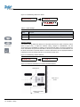
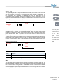
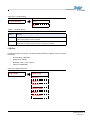
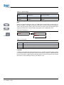
1
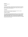
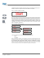
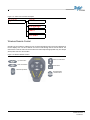
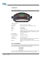
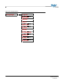
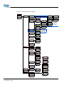
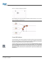
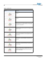
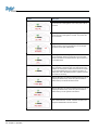
CenterLine
Software Version 2.02
Copyrights
© 2007 TeeJet Technologies Inc. All rights reserved. No part of this document or the computer
programs described in it may be reproduced, copied, photocopied, translated, or reduced in any
form or by any means, electronic or machine readable, recording or otherwise, without prior
written consent from TeeJet Technologies, Inc.
Trademarks
Unless otherwise noted, all other brand or product names are trademarks or registered
trademarks of their respective companies or organizations.
Limitation of Liability
TEEJET TECHNOLOGIES, INC. PROVIDES THIS MATERIAL “AS IS” WITHOUT WARRANTY
OF ANY KIND, EITHER EXPRESSED OR IMPLIED. NO COPYRIGHT LIABILITY OR PATENT
IS ASSUMED. IN NO EVENT SHALL TEEJET TECHNOLOGIES, INC. BE LIABLE FOR ANY
LOSS OF BUSINESS, LOSS OF PROFIT, LOSS OF USE OR DATA, INTERRUPTION OF
BUSINESS, OR FOR INDIRECT, SPECIAL, INCIDENTAL, OR CONSEQUENTIAL DAMAGES
OF ANY KIND, EVEN IF TEEJET TECHNOLOGIES HAS BEEN ADVISED OF SUCH DAMAGES
ARISING FROM TEEJET SOFTWARE.
TABLE OF CONTENTS
CHAPTER 1 - INTRODUCTION . . . . . . . . . . . . . . . . . . . . . . . . . . . . . . . 1
STRAIGHT OR CURVED GUIDANCE . . . . . . . . . . . . . . . . . . . . . . . . . . . . . . . . . . . . 1
WIRELESS REMOTE CONTROL UNIT . . . . . . . . . . . . . . . . . . . . . . . . . . . . . . . . . . . 1
LIGHTBAR DISPLAY . . . . . . . . . . . . . . . . . . . . . . . . . . . . . . . . . . . . . . . . . . . . . . . . . 1
MENU ITEMS AND PICK LIST TEXT . . . . . . . . . . . . . . . . . . . . . . . . . . . . . . . . . . . . 1
Wireless Remote Control . . . . . . . . . . . . . . . . . . . . . . . . . . . . . . . . . . . . . . . . . . . . . . . . . . 3
LIGHTBAR . . . . . . . . . . . . . . . . . . . . . . . . . . . . . . . . . . . . . . . . . . . . . . . . . . . . . . . . . 4
FCC STATEMENT . . . . . . . . . . . . . . . . . . . . . . . . . . . . . . . . . . . . . . . . . . . . . . . . . . . 4
CHAPTER 2 - SETUP . . . . . . . . . . . . . . . . . . . . . . . . . . . . . . . . . . . . . . . 5
QUICK START GUIDE . . . . . . . . . . . . . . . . . . . . . . . . . . . . . . . . . . . . . . . . . . . . . . . . 5
First Time Start-Up Sequence . . . . . . . . . . . . . . . . . . . . . . . . . . . . . . . . . . . . . . . . . . . . . . 5
Typical Start-Up Sequence . . . . . . . . . . . . . . . . . . . . . . . . . . . . . . . . . . . . . . . . . . . . . . . . 5
CENTERLINE SETUP . . . . . . . . . . . . . . . . . . . . . . . . . . . . . . . . . . . . . . . . . . . . . . . . 7
Guidance Mode . . . . . . . . . . . . . . . . . . . . . . . . . . . . . . . . . . . . . . . . . . . . . . . . . . . . . . . . . 7
Lightbar . . . . . . . . . . . . . . . . . . . . . . . . . . . . . . . . . . . . . . . . . . . . . . . . . . . . . . . . . . . . . . 15
System Setup . . . . . . . . . . . . . . . . . . . . . . . . . . . . . . . . . . . . . . . . . . . . . . . . . . . . . . . . . . 19
TOOLS . . . . . . . . . . . . . . . . . . . . . . . . . . . . . . . . . . . . . . . . . . . . . . . . . . . . . . . . . . . 23
Receiver . . . . . . . . . . . . . . . . . . . . . . . . . . . . . . . . . . . . . . . . . . . . . . . . . . . . . . . . . . . . . .
Lightbar . . . . . . . . . . . . . . . . . . . . . . . . . . . . . . . . . . . . . . . . . . . . . . . . . . . . . . . . . . . . . .
Level . . . . . . . . . . . . . . . . . . . . . . . . . . . . . . . . . . . . . . . . . . . . . . . . . . . . . . . . . . . . . . . . .
e-Dif . . . . . . . . . . . . . . . . . . . . . . . . . . . . . . . . . . . . . . . . . . . . . . . . . . . . . . . . . . . . . . . . .
e-Dif Info . . . . . . . . . . . . . . . . . . . . . . . . . . . . . . . . . . . . . . . . . . . . . . . . . . . . . . . . . . . . . .
Demo . . . . . . . . . . . . . . . . . . . . . . . . . . . . . . . . . . . . . . . . . . . . . . . . . . . . . . . . . . . . . . . .
Next . . . . . . . . . . . . . . . . . . . . . . . . . . . . . . . . . . . . . . . . . . . . . . . . . . . . . . . . . . . . . . . . .
To Start . . . . . . . . . . . . . . . . . . . . . . . . . . . . . . . . . . . . . . . . . . . . . . . . . . . . . . . . . . . . . . .
24
24
24
24
25
25
25
25
CHAPTER 3 - OPERATION . . . . . . . . . . . . . . . . . . . . . . . . . . . . . . . . . 27
OPERATION MENU . . . . . . . . . . . . . . . . . . . . . . . . . . . . . . . . . . . . . . . . . . . . . . . . . 27
New? Resume? . . . . . . . . . . . . . . . . . . . . . . . . . . . . . . . . . . . . . . . . . . . . . . . . . . . . . . . . 27
Apply On/Off . . . . . . . . . . . . . . . . . . . . . . . . . . . . . . . . . . . . . . . . . . . . . . . . . . . . . . . . . . . 28
Return To Point . . . . . . . . . . . . . . . . . . . . . . . . . . . . . . . . . . . . . . . . . . . . . . . . . . . . . . . . 30
HEADLAND GUIDANCE . . . . . . . . . . . . . . . . . . . . . . . . . . . . . . . . . . . . . . . . . . . . . 30
Reference Guideline . . . . . . . . . . . . . . . . . . . . . . . . . . . . . . . . . . . . . . . . . . . . . . . . . . . . . 31
Switching From Headland To Straight-Line Guidance . . . . . . . . . . . . . . . . . . . . . . . . . . . 31
Headland Guidance Lightbar Graphics . . . . . . . . . . . . . . . . . . . . . . . . . . . . . . . . . . . . . . 32
STRAIGHT-LINE GUIDANCE . . . . . . . . . . . . . . . . . . . . . . . . . . . . . . . . . . . . . . . . . 33
Curved AB Guidance . . . . . . . . . . . . . . . . . . . . . . . . . . . . . . . . . . . . . . . . . . . . . . . . . . . . 34
APPLIED AREA DETECTION . . . . . . . . . . . . . . . . . . . . . . . . . . . . . . . . . . . . . . . . . 35
Applied Area Detection . . . . . . . . . . . . . . . . . . . . . . . . . . . . . . . . . . . . . . . . . . . . . . . . . . . 35
Neighboring Swath Detection . . . . . . . . . . . . . . . . . . . . . . . . . . . . . . . . . . . . . . . . . . . . . . 36
LIGHTBAR INDEX . . . . . . . . . . . . . . . . . . . . . . . . . . . . . . . . . . . . . . . . . . . . . . . . . . 36
SWATH MANAGER 5 . . . . . . . . . . . . . . . . . . . . . . . . . . . . . . . . . . . . . . . . . . . . . . . 39
Installation . . . . . . . . . . . . . . . . . . . . . . . . . . . . . . . . . . . . . . . . . . . . . . . . . . . . . . . . . . . . 39
TILT COMPENSATION MODULE . . . . . . . . . . . . . . . . . . . . . . . . . . . . . . . . . . . . . . 41
Tilt Compensation Module Installation . . . . . . . . . . . . . . . . . . . . . . . . . . . . . . . . . . . . . . . 42
EXITING OPERATION . . . . . . . . . . . . . . . . . . . . . . . . . . . . . . . . . . . . . . . . . . . . . . . 43
CenterLine 2.02 i
98-05054 R6
ii
CHAPTER 1 - INTRODUCTION
CenterLine is an economical lightbar guidance system that is controlled by a wireless remote. CenterLine provides accurate Straight-Line and Curved Guidance for use in spraying, seeding, and other
related jobs at a cost that rivals foam markers. The CenterLine product is equipped with a combination Beacon/WAAS or WAAS only DGPS receiver, providing sub-meter, pass-to-pass positioning
accuracy. The wireless remote control is used to configure and operate the system through menus
and options displayed on the lightbar.
CenterLine’s attractive design combines compact size with fully adjustable, easy to see LEDs. Using
dedicated buttons on the wireless remote, the lightbar can be dimmed to efficiently run at night and
brightened for viewing in full sunlight.
STRAIGHT OR CURVED GUIDANCE
CenterLine guides along various types of swaths with sub-meter, pass-to-pass accuracy. Select the
driving pattern and CenterLine determines the closest swath to follow. There is no need to decide a
guidance pattern ahead of time or commit to a pattern for the entire job. CenterLine allows the
switching of patterns during operation, determining when a new pattern is being used and keeping
the operator informed of the current status.
WIRELESS REMOTE CONTROL UNIT
CenterLine’s ergonomic, handheld remote control is easier to use than most television remotes.
Seven easy-to-read buttons allow for the scrolling of menus displayed on the lightbar. The remote
keypad is backlit for nighttime operation. Three AAA batteries (included) power the unit for an entire
season.
The small, powerful remote permits mounting the weather-resistant lightbar outside on the hood or in
the cab. When mounted outside, wireless communication permits easy operation while the cab stays
clean and sealed from dust and contaminants.
LIGHTBAR DISPLAY
A text display on the lightbar reports a choice of guidance information. It also warns when an area of
the field is entered that has already been applied. Guidance text information can be turned off, if preferred. Two of the following guidance messages are available for selection during operation to monitor progress:
•
Cross-Track Error
•
Current Swath Number
•
Vehicle Speed
•
Applied Area
•
Vehicle Course On Ground (COG)
MENU ITEMS AND PICK LIST TEXT
Throughout this User’s Guide, menu item text is displayed between < > characters (i.e., <START>).
Buttons on the remote control are denoted in italics (i.e., Arrow buttons) and will be displayed in the
margin of the User’s Guide.
Arrow buttons
Most of the figures in this guide are menu items that are displayed in the text window of the lightbar.
This text represents either a menu item, such as <GUIDANCE>, or a list item, such as <METRIC>.
CenterLine 2.02 1
98-05054 R6
The lightbar text window can display a single line of text up to ten characters in length. Figure 1-1
illustrates an example of a single text line that would be displayed on the lightbar.
Figure 1-1: Example of Lightbar Text Display
Start
Arrow buttons
Figures with multiple menu items are depicted with menu items above and below, and with submenu
items located to the right of the text item currently in view. Figure 1-2 represents several menu items.
The current menu item in view is <SETUP> and is denoted with a black arrow to the right of the text.
The figure shows that the Arrow buttons can be used to scroll between <START>, <SETUP>, and
<TOOLS>. If the Enter button is pressed, the display will progress into <SETUP> and continue with
<GUIDANCE> menu options. The Arrow buttons would then be able to scroll between <GUIDANCE>, <LIGHTBAR>, <SYSTEM>, etc.
Enter button
Figure 1-2: Example of Multiple Text Lines
Start
Setup
Guidance
Tools
Lightbar
System
There are two additional menu items that are located in almost every menu:
•
<NEXT>
•
<TO START>
Figure 1-3 illustrates the <NEXT> and <TO START> menu items in the System Setup menu list.
Pressing the Enter button when <NEXT> is displayed will launch the next menu heading. For example, during Lightbar Setup, pressing Enter at <NEXT> will launch <SYSTEM>. Once in System
Setup, pressing the Escape (ESC) button at <NEXT> will launch the <LIGHTBAR> menu again.
Selecting <TO START> automatically reverts the operator back to the main menu. This is useful
when it is necessary to make only minor modifications and quickly resume operation.
2 Chapter 1 - Introduction
Figure 1-3: <Next> and <To Start> Examples
Units
System
Language
Next
To Start
Wireless Remote Control
Operation of the CenterLine software occurs via remote keypad input and menu items displayed in
the text display area. The Arrow buttons are used to scroll through menus and sub-menus. The
Enter button is used to enter menus and sub-menus and accepts the appropriate entry. The Escape
(ESC) button acts as a cancel button.
Figure 1-4: Wireless Remote Control
Up Arrow button
Return to Point button
Down Arrow button
Enter button
Menu/Escape button
Brighter/Dimmer
contrast buttons
CenterLine 2.02 3
98-05054 R6
LIGHTBAR
Figure 1-5: CenterLine Lightbar
Lightbar Specifications
Housing Material
ABS/Poly carbonate alloy construction.
Dimensions
3.70” H x 9.40” W x 3.80” D / 95mm x 240mm x 100mm
Weight
0.8 lbs / 0.36 kg
Processor
Intel StrongARM
Memory
16 MB Ram, 2 MB Flash
LEDs
High-lumen red, yellow, and green radial light pattern and 10-character LED alphanumeric text display. Full brightness control adjustment using wireless remote.
Operating Voltage
10-14 VDC
Operating Temperature
32o to 160oF / 0o to 70o C
Storage Temperature
-40o to 185o F / -40o to 85o C
I/O to DGPS
1 asynchronous RS232
I/O to Control Unit
Wireless link operating at 433 MHz. FCC Part 15 and Industry Canada RS-210 certified. Other certifications pending.
Mounting
Mounting bracket supplied. Magnetic and suction mounts are
optional.
FCC STATEMENT
This device complies with Part 15 of the FCC Rules. Operation is subject to the following two conditions: (1) This device may not cause harmful interference; and (2) this device must accept any interference received, including interference that may cause undesired operation.
QS7CL7850094
QS7CL7850107
TR19JN96.008
Changes or modifications to the product, not expressly approved by TeeJet Technologies, Inc. could
void the user’s authority as granted under Part 15 of the FCC Rules to operate the equipment.
4 Chapter 1 - Introduction
CHAPTER 2 - SETUP
It is assumed that the CenterLine system has been properly installed. Refer to the following CenterLine diagrams for system configuration.
QUICK START GUIDE
First Time Start-Up Sequence
1.
Turn ON power to CenterLine.
2.
The lightbar will perform a start-up sequence.
3.
The lightbar will display the current software version.
4.
The lightbar will display <START>.
5.
Using the Arrow buttons, scroll until <SETUP> is displayed on the lightbar. Press the
Enter button.
6.
Configure the CenterLine system by choosing the appropriate settings under <GUIDANCE>, <LIGHTBAR>, and <SYSTEM>. It is important to enter the correct swath width for
operation.
7.
Use the Arrow buttons to locate <TO START>. Press the Enter button. The operator will
return to the main menu.
8.
Once <START> is displayed on the lightbar, press ENTER to begin operation.
Arrow buttons
Enter button
Typical Start-Up Sequence
1.
Turn ON power to CenterLine.
2.
The lightbar will perform a start-up sequence.
3.
The lightbar will display the current software version.
4.
The lightbar will display <START>.
5.
<START> will remain visible on the lightbar until the Enter button is pressed to begin operation or the Arrow buttons are pressed to select a menu option.
CenterLine 2.02 5
98-05054 R6
Figure 2-1: CenterLine Without DGPS Receiver
Lightbar
78-50112
A GPS data cable is
required but not provided in the kit.
Wireless Remote
78-50107
Adapter Cable
15’ / 5 m
45-05338
CenterLine Power Cable
12’ / 4 m 45-05324
5 Amp
Boom Sense +12V when
booms are ON
GPS Data Cable
15’ / 5 m
45-05337
Ignition Sense +12V
when ignition is ON
Power Cable
12’ / 4 m 45-05298
to battery
Figure 2-2: CenterLine With DGPS Receiver
Lightbar
78-50112
Wireless Remote
78-50107
RX400P
78-50062
RX370P
78-50148
GPS Data Cable 15’ / 5 m
45-05338
Inline fuse
CenterLine Power Cable
12’ / 4 m 45-05324
5 Amp
GPS Data Cable 15’ / 5 m
45-05337
Ignition Sense +12V
when ignition is ON
Power Cable
12’ / 4 m 45-05298
to battery
6 Chapter 2 - Setup
Boom Sense
+12V when
booms are ON
CENTERLINE SETUP
CenterLine Setup allows for the configuration of the CenterLine product to best suit current guidance
and mapping needs. For a complete overview of the setup process, refer to Figure 2-31 (page 22).
CenterLine Setup consists of three sub-menus:
•
Guidance
•
Lightbar
•
System
The top level of CenterLine software contains three menus available for selection: <START>,
<SETUP>, and <TOOLS>. To access the setup menus, use the Arrow buttons to scroll to <SETUP>
and press the Enter button. Once in <SETUP> mode, menu options will consist of <GUIDANCE>,
<LIGHTBAR>, and <SYSTEM>. Access to setup options is achieved by pressing the Enter button.
Figure 2-3: CenterLine Setup Flow
Arrow buttons
Start
Setup
Guidance
Tools
Lightbar
Enter button
System
Guidance Mode
Guidance Mode allows for the establishment of several parameters that pertain to guidance functionality. To access Guidance Mode, use the Arrow buttons to scroll through the menu selections
until <GUIDANCE> appears on the lightbar. Press the Enter button.
If the first menu item displayed is <SWATH MAN>, Swath Manager 5 has been detected on the system and needs to be configured. Refer to CHAPTER 2 - SWATH MANAGER for additional information.
CenterLine 2.02 7
98-05054 R6
Figure 2-4: Guidance Setup Flow
Guidance
Width
Ahead
Antenna
Status
Alarm
GPS Type
1 Hz MSG
Next
To Start
Table 2-1: Guidance Default Settings
Setting
Default Value
Change at Initial Startup
Width
30.0 feet/10 meters
Required
Ahead
1.5 seconds
Optional
Antenna - Direction
None
Recommended
Antenna - Distance
0.0 feet
Recommended
Antenna - Height
9.8 feet / 2.9 meters
Recommended
Status Detect
Off
Optional
Alarm
Off
Recommended
GPS Type
DGPS
Recommended
1 Hz MSG
Yes
Not Recommended
Swath Manager 5
The Guidance parameter <SWATH MAN> is only displayed when Swath Manager 5 is connected to
the system. If Swath Manager 5 is not being used, this section is not required and can be skipped.
To adjust <SWATH MAN> settings in <GUIDANCE> mode, use the Arrow keys until <SWATH MAN>
is displayed and press the Enter button. The Swath Manager menu contains four parameters:
Arrow buttons
Enter button
8 Chapter 2 - Setup
•
% overlap
•
Sections
•
Width 1-5
•
Delay
Figure 2-5: Swath Manager 5 Setup
Guidance
Setup
Swath Man
Table 2-2: Swath Manager Settings
Setting
Description
% Overlap
Boom sections are activated and deactivated based on the percentage of boom overlap
setting (0%, 50%, and 100%)
Sections
The number of sections (1-5) active on the system.
Width 1-5
The width for each boom 1-5.
Delay
The delay in seconds to turn the booms on and off when entering/exiting applied zones.
% Overlap
%Overlap determines the amount of overlap allowance to eliminate skips in application. Enter the
appropriate pattern by using the Arrow buttons to select 0%, 50%, or 100% and press the
Enter button to accept the setting.
Arrow buttons
Enter button
Figure 2-6: % Overlap Settings
% Overlap
0%
50%
100%
Figure 2-7: % Overlap Illustration
CenterLine 2.02 9
98-05054 R6
Sections
Enter the number of sections that are active in the system. Use the Arrow buttons to scroll to the
appropriate number (1 - 5) and press the Enter button to accept the setting.
Figure 2-8: Number of Sections
Sections
5
Arrow buttons
Width
Enter button
Enter the width in feet / meters for boom section 1 by using the Arrow buttons to scroll through the
options, followed by the Enter button. Repeat the process for the remaining boom sections. The
total width of all boom sections is NOT the width that will be used for guidance. Refer to
CHAPTER 2 - WIDTH for additional information.
Figure 2-9: Boom Section Width
Width 1
10
Delay
Enter the delay in seconds. This acts as the look ahead to turn booms on and off when entering and
exiting applied zones.
Entering Applied Zones: When entering an applied zone, the setting acts as a look ahead and turns
the booms off prior to entering the zone according to the number of seconds entered in Delay Setup.
The setting allows time for the valves to shut off.
Exiting Applied Zones: When exiting an applied zone, the setting acts as a look ahead and turns the
booms on prior to exiting the zone according to the number of seconds entered in Delay Setup. The
setting allows time for the booms to re-engage before exiting the applied area.
Figure 2-10: Delay
Delay
1.5
Width
The Guidance parameter Width measures the distance between guidelines. This width is typically
the vehicle implement width, otherwise known as spread width. Setting this width slightly smaller
than the actual width reduces skips. Setting this width slightly larger than the actual width reduces
overlap. To adjust width setting, select <GUIDANCE> followed by the Enter button. Use the
Arrow buttons and select <WIDTH>, followed by the Enter button. To increase the width, press the
Up Arrow button. To decrease the width, press the Down Arrow button. Press the Enter button once
the desired width is established. Width value is established in 0.1 foot increments.
10 Chapter 2 - Setup
Figure 2-11: Guidance Width
Width
58.5
Ahead
The Look Ahead value, Ahead, is the number of seconds ahead of the vehicle the operator desires
the software to calculate the cross track error. Based on the vehicle’s speed and trajectory combined
with the look ahead value, CenterLine can determine where the vehicle will be with respect to the
current guideline. This setting will vary based on the operator’s driving ability and preference. This
value is only used during Parallel Guidance. It is not used during Headland Guidance or Circle Pivot.
A look ahead value that best fits the operator will result in smoother guidance operation. Typically,
this value is set to 1.5 or 2.0 seconds. To adjust Ahead settings, select <GUIDANCE> followed by
the Enter button. Use the Arrow buttons until <AHEAD> is displayed in the text window. Press the
Enter button and use the Arrow buttons to adjust the value. Press the Enter button to save the settings and return to the Guidance setup menu.
Arrow buttons
Enter button
Figure 2-12: Ahead Value
Ahead
1.5
Antenna
The Antenna sub-menu defines the spatial relationship between the GPS antenna and the vehicle
implement or delivery point. The GPS antenna should always be mounted along the vehicle’s center
line (refer to Figure 2-16). The two primary antenna settings are <DIRECTION> and <DISTANCE>.
To enter the Antenna sub-menu, navigate to <GUIDANCE>, use the Arrow buttons until
<ANTENNA> is displayed, and press the Enter button. Several options will be displayed: <DIRECTION>, <TO START>, <NEXT>, <HEIGHT>, and <DISTANCE>. Press the Enter button to save the
settings and return to the Guidance setup menu.
Figure 2-13: Antenna Sub-Menu
Guidance
Antenna
Direction
Antenna - Direction
The Direction sub-menu defines the direction from the swath (refer to Figure 2-16). To change the
Direction setting, navigate to <GUIDANCE>, use the Arrow buttons until <ANTENNA> is displayed,
and press the Enter button. Use the Arrow buttons to select <DIRECTION> and press the
Enter button. Scroll through the direction list using the Arrow buttons until the desired direction is displayed in the text window. Press the Enter button to save the setting and return to the Guidance
setup menu.
CenterLine 2.02 11
98-05054 R6
Figure 2-14: Establishing Direction to Swath
Back
Direction
Forward
Table 2-3: Swath Settings
Setting
Description
Back
GPS receiver is behind the swath or delivery point on the vehicle along the center line.
Forward
GPS receiver is in front of the swath or delivery point on the vehicle along the center line.
Antenna - Distance
Arrow buttons
The Distance setting defines the distance from the GPS antenna to the swath or delivery location
(refer to Figure 2-16). To adjust the Distance setting, navigate to <GUIDANCE>, use the
Arrow buttons until <ANTENNA> is displayed, and press the Enter button. Use the Arrow buttons to
select <DISTANCE> and press the Enter button. Use the Up Arrow button to increase distance; use
the Down Arrow button to decrease distance. Press the Enter button once the appropriate distance
is displayed to save the settings and return to the Guidance setup menu.
Enter button
Figure 2-15: Establishing Antenna Distance
22.5
Distance
Figure 2-16: Direction and Distance to Swath from DGPS Receiver
GPS Antenna
Center Line of
Vehicle
Distance To Swath
Direction From Swath
(Forward)
12 Chapter 2 - Setup
Antenna - Height
The Height setting defines the height of the GPS antenna to the ground surface. This value is used
only when a tilt sensor is connected. To change the height setting, navigate to <GUIDANCE>, use
the Arrow buttons until <ANTENNA> is displayed, and press the Enter button. Use the
Arrow buttons to select <HEIGHT> and press the Enter button. Using the Arrow buttons, enter the
height value until the desired distance is displayed in the text window. Press the Enter button to save
the setting and return to the Guidance setup menu.
Arrow buttons
Figure 2-17: Establishing Antenna Height
9.8
Height
Enter button
Status
NOTE:
If a Swath Manager 5 is connected to the system, the Status option will be removed from the main
setup. Status setup is used to auto detect implement status. When the status detect is properly
implemented, CenterLine will detect whether product delivery is ON or OFF based on the vehicle
product ON/OFF switch. Refer to Figures 2-1 and 2-2 for the location of status connect (boom
sense) wiring.
To adjust Status, navigate to <GUIDANCE>, use the Arrow buttons until <STATUS> is displayed and
press the Enter button. Options are either ON or OFF. Use the Arrow buttons to choose the appropriate option and press the Enter button to save the settings and return to the Guidance setup menu.
Figure 2-18: Status Selection
Status
When <STATUS>
is set to ON, +12V
must be supplied
to the boom sense
wire when booms
are ON. If this
does not occur,
applied
area
detection will not
work. Refer to the
CenterLine wiring
tips document 9801095.
Off
On
Table 2-4: Status Settings
Setting
Description
Off
No status detect is implemented. This is the default setting.
On
Status detect assumes a single swath centered on the vehicle.
Alarm
The Alarm setting, when enabled, notifies the operator when entering a previously applied area. The
text window will display <APPLIED> when the implement swath enters a previously applied area of a
field. To adjust the alarm setting, navigate to <GUIDANCE>, use the Arrow buttons until <ALARM>
is displayed and press the Enter button. Options are either ON or OFF. Use the Arrow buttons to
choose the appropriate option and press the Enter button to save the settings and return to the Guidance setup menu.
CenterLine 2.02 13
98-05054 R6
Figure 2-19: Alarm Selection
Alarm
Off
On
Table 2-5: Alarm Settings
Setting
Description
Off
No applied area detection.
On
Applied area detection. Alarm will sound.
GPS Type
Arrow buttons
GPS Type indicates to the CenterLine system if the GPS receiver is differentially corrected. To adjust
the GPS Type, navigate to <GUIDANCE>, use the Arrow buttons until <GPS TYPE> is displayed
and press the Enter button. Options include <DGPS> and <GPS>. Select the appropriate option and
press the Enter button to save the settings and return to the Guidance setup menu.
Enter button
Figure 2-20: GPS Type Selection
GPS Type
DGPS
GPS
Table 2-6: GPS Type Settings
Setting
Description
GPS
GPS receiver with no differential correction, capable of providing positioning accuracy of
approximately 10 meters.
DGPS
GPS receiver with differential correction, capable of providing sub-meter positioning accuracy.
1 Hz MSG
A 1 Hz data rate is not recommended for vehicle guidance, so a “GPS SLOW” message will be displayed on the lightbar to notify the operator if the GPS receiver is set to a 1 Hz data rate. However,
there are some areas where the 1 Hz rate is used. For those areas, the ability to disable the “GPS
SLOW” message has been established.
To enable or disable the “GPS SLOW” message, navigate to <GUIDANCE>, use the Arrow buttons
until <1 HZ MSG> is displayed and press the Enter button. Options are <YES> and <NO>. Select
the appropriate option using the Arrow buttons and press the Enter button to save the settings and
return to the Guidance setup menu.
14 Chapter 2 - Setup
Figure 2-21: 1 Hz MSG Setting
1 Hz MSG
Yes
No
Table 2-7: 1 Hz MSG Settings
Setting
Description
Yes
When the data rate of the GPS receiver is set to 1 Hz, a <GPS SLOW> message is sent to the
lightbar and the guidance function is disabled.
No
When the data rate of the GPS receiver is set to 1Hz, a <GPS SLOW> message is sent to the
lightbar when the operator first begins operation, but guidance is allowed.
Lightbar
Lightbar setup allows the selection of several parameters related to the lightbar. There are five lightbar settings:
•
Drive Sensitivity <SPACING>
•
Display Mode <MODE>
•
Messages <TEXT 1> and <TEXT 2>
•
Steer Bar <STEER BAR>
Figure 2-22: Lightbar Setup Flow
Lightbar
Spacing
Mode
Text 1
Text 2
Steer Bar
Next
To Start
CenterLine 2.02 15
98-05054 R6
Table 2-8: Lightbar Menu Settings
Setting
Default Value
Change at Startup
Spacing
1.5 feet
Optional
Mode
Swath
Optional
Text 1
X-Track Error
Optional
Text 2
Applied Area
Optional
Steer Bar
No
Optional
Spacing
Arrow buttons
The Spacing setting allows the selection of the distance that a single light on the lightbar LED represents. To change the spacing setting, navigate to <LIGHTBAR>, use the Arrow buttons until <SPACING> is displayed and press the Enter button. Use the Up Arrow button to increase distance; use the
Down Arrow button to decrease distance. Press the Enter button once the appropriate distance is
displayed to save the settings and return to the Lightbar setup menu. The spacing range is 0.5 feet
to 9.5 feet in 0.1 foot increments.
Enter button
Figure 2-23: Establishing Spacing Distance
Spacing
1.5
Mode
The Mode setting defines how the row of LEDs are interpreted. The center stack of LEDs can represent either the current guideline or the vehicle. To change the Mode setting, navigate to <LIGHTBAR>, use the Arrow buttons until <MODE> is displayed and press the Enter button. Options
include <VEHICLE> and <SWATH>. Use the Arrow buttons to select the appropriate option and
press the Enter button to save the setting and return to the Lightbar setup menu.
Figure 2-24: Establishing Mode
Mode
16 Chapter 2 - Setup
Vehicle
Swath
Table 2-9: Mode Settings
Setting
Description
Swath
The center stack of LEDs represent the current guideline. Steer the vehicle to bring the moving
LED back to center.
Vehicle
The center stack of LEDs represent the vehicle’s position. Steer the vehicle to bring the center
lights toward the moving LED.
Text 1 and Text 2
Text 1 and Text 2 settings allow the operator to select text messages from pre-determined guidance
information messages. The messages are displayed on the lightbar text window for 15 seconds
when first enabled and used during guidance operation. A maximum of two text messages can be
displayed.
Text 1
To select the Text1 setting, navigate to <LIGHTBAR>, use the Arrow buttons until <TEXT 1> is displayed and press the Enter button. Scroll through the available options using the Arrow buttons until
the desired message is located. Press the Enter button to save the setting and advance to the
<TEXT 2> menu item.
Figure 2-25: Selecting Text 1 Message
Text 1
Arrow buttons
Enter button
X-Track
Swath#
Speed
Area
Course
Off
CenterLine 2.02 17
98-05054 R6
Table 2-10: Text 1 Settings
Arrow buttons
Message
Description
X-Track
Displays the error (in distance) between the current guideline and the vehicle position.
Swath #
Displays the current guideline number.
Ground Speed
Displays the vehicle ground speed.
Area Applied
Displays the amount of area covered, sprayed, or spread in acres or hectares.
COG
Course on Ground, displays the vehicle heading in degrees.
Off
When OFF is selected, no message is displayed in the message slot.
Text 2
To select the Text 2 setting, navigate to <LIGHTBAR>, use the Arrow buttons until <TEXT 2> is displayed and press the Enter button. Scroll through the available options using the Arrow buttons until
the desired message is located. Press the Enter button to save the setting and advance to the
<STEER BAR> menu item.
Enter button
Figure 2-26: Selecting Text 2 Message
Text 2
X-Track
Swath#
Speed
Area
Course
Off
Table 2-11: Text 2 Settings
18 Chapter 2 - Setup
Message
Description
X-Track
Displays the error (in distance) between the current guideline and the vehicle position.
Swath #
Displays the current guideline number.
Ground Speed
Displays the vehicle ground speed.
Area Applied
Displays the amount of area covered, sprayed, or spread in acres or hectares.
COG
Course on Ground, displays the vehicle heading in degrees.
Off
When OFF is selected, no message is displayed in the message slot.
Steer Bar
The Steer Bar setting determines how the LED steering display will appear. The LEDs represent the
vehicle track in relation to the current guideline. They can be displayed as a single LED or as a solid
bar. To change the steer bar setting, navigate to <LIGHTBAR>, use the Arrow buttons until <STEER
BAR> is displayed and press the Enter button. Use the Arrow buttons to select either YES or NO.
Press the Enter button to save the setting and return to the <LIGHTBAR> menu.
Arrow buttons
Figure 2-27: Selecting Steer Bar Option
Steer Bar
No
Yes
Enter button
Table 2-12: Steer Bar Settings
Setting
Description
No
The LEDs, representing the vehicle track in relation to the current guideline, are shown as a
single LED.
Yes
The LEDs, representing the vehicle track in relation to the current guideline, are shown as a
solid bar.
System Setup
System Setup allows for the selection of settings that affect the entire CenterLine product. There are
two settings that impact CenterLine:
•
Unit
•
Language
Figure 2-28: System Setup
System
Unit
Language
Next
To Start
CenterLine 2.02 19
98-05054 R6
Table 2-13: System Settings
Setting
Default Value
Change Upon Startup
Unit
US
Optional
Language
English
Optional
Unit
System units allow the selection of either U.S. or Metric units of measurement. To change the system units, navigate to <SYSTEM> and press the Enter button. Use the Arrow buttons to navigate to
<UNIT> and press the Enter button. Options are either US or Metric. Select the appropriate option
and press the Enter button to save the setting and progress to the <LANGUAGE> menu.
Arrow buttons
Figure 2-29: Unit selection
Unit
US
Metric
Enter button
Table 2-14: Unit Setting
Setting
Description
US
All units are entered and displayed in feet, miles, and acres. This is the default setting.
Metric
All units are entered and displayed in meters, kilometers, and hectares.
Language
CenterLine is pre-loaded with several language options. To change the system language, navigate
to <SYSTEM> and press the Enter button. Use the Arrow buttons to navigate to <LANGUAGE> and
press the Enter button. Toggle through the language options using the Arrow buttons and press the
Enter button to save the setting and return to the <SETUP> menu.
20 Chapter 2 - Setup
Figure 2-30: Language Options
Language
English
Swedish
Danish
Dutch
German
French
Italian
Portuguese
Spanish
Polish
Russian
CenterLine 2.02 21
98-05054 R6
Figure 2-31: CenterLine Setup Flow Diagram
Start
Setup
Guidance
Tools
Swath Man
%Overlap
0%
Width
30.0 (default)
Sections
50%
Ahead
1.5 (default)
Width 1-5
100%
Antenna
Direction
Forward
Delay
Back
Next
Distance
0.0 (default)
To Start
Height
9.8 (default)
Next
Status
Off
On
Alarm
Removed from
menu setup when
Swath Manager 5
is connected
Off
On
GPS Type
DGPS
GPS
1 Hz MSG
Yes
No
Next
To Start
Lightbar
Spacing
1.5 (default)
Mode
Vehicle
Swath
Text 1
X-Track
Text 2
Swath #
Speed
Steer Bar
Area
English
Course
Swedish
Off
Danish
No
Dutch
Yes
System
French
To Start
Italian
Units
Next
To Start
Metric
Portuguese
US
Spanish
Language
Polish
Next
Russian
To Start
22 Chapter 2 - Setup
German
Next
Only available
when Swath
Manager 5 is
connected
TOOLS
The Tools menu contains several functions that provide basic systems diagnostics. The tools menu
is accessed from the main menu. Use the Arrow buttons to select <TOOLS> and press the Enter
button.
Figure 2-32: Tools Menu Flow
Tools
Arrow buttons
Receiver
Lightbar
Level
E-Dif
E-Dif Info
Demo
Next
To Start
Enter button
Table 2-15: Tools Menu Items
Menu Item
Description
Receiver
Checks the status of a connected GPS receiver
Lightbar
Tests the functionality of the CenterLine lightbar LEDs and text window.
Level
Only appears if a Tilt Compensation Module is detected. When on a level surface, use the level
function to calibrate the Tilt Module.
e-Dif
Only appears if an e-Dif GPS receiver is detected by the CenterLine system. Re-calibrates the
e-Dif receiver.
e-Dif Info
Only appears if an e-Dif GPS receiver is detected by the CenterLine system. Displays current
position information.
Demo
Activates a simulated CenterLine session.
Next
Advances to the next Setup menu item.
To Start
Returns the operator to the main menu.
CenterLine 2.02 23
98-05054 R6
Receiver
Arrow buttons
The Receiver diagnostic test displays the attached GPS receiver’s current configuration and status.
The information is displayed in the text window of the lightbar. To begin the receiver check, navigate
to <TOOLS> and press the Enter button. Use the Arrow buttons to select <RECEIVER> and press
the Enter button. The lightbar will display the diagnostic message.
Table 2-16: Receiver Messages
Enter button
Message
Description
GPS Status
If the lightbar is not receiving GPS data, the text window message will be displayed as
<NO GPS>. If the lightbar is receiving GPS data but the data is not differentially corrected, the text window message will be displayed as <GPS>.
DGPS Status
If the lightbar is receiving GPS data that is differentially corrected, the text window will
display the message <DGPS>.
NMEA Strings
Returns the name of each NMEA string currently being received from the receiver. For
example, if the NMEA GPGGA string is being received from the receiver, the text window will display <GGA>.
Data Rate
Returns the current receiver data rate. This is typically 5 Hz. The rate is displayed in
the text window (e.g., <5 HZ>).
Lightbar
The Lightbar diagnostic test initiates an illumination sequence of all the LEDs in the test window, followed by a brightness control sequence. This will allow the verification that all LEDs on the CenterLine lightbar are working correctly. To begin the lightbar check, navigate to <TOOLS> and press the
Enter button. Use the Arrow buttons to select <LIGHTBAR> and press the Enter button. The illumination sequence will begin. Once the test has concluded, the lightbar will display <LIGHTBAR>.
Level
Once the antenna height has been entered (refer to CHAPTER 2 - ANTENNA - HEIGHT) and the
vehicle is situated on a level surface, the Tilt Compensation Module should be calibrated (leveled).
To access the level feature, navigate to <TOOLS> and press the Enter button. Use the Arrow buttons to select <LEVEL> and press the Enter button. Highlight the Level menu item using the
Arrow buttons and press the Enter button. The lightbar will display <WAIT> during calibration followed by <READY> once the calibration is complete.
e-Dif
The accuracy of the position information provided by the e-Dif GPS receiver slowly deteriorates with
time since the last calibration. Due to this factor, it is recommended that the e-Dif receiver be re-calibrated approximately every 1 to 2 hours to maintain accuracy for position information. The e-Dif tool
allows the operator to re-calibrate the e-Dif receiver by halting the vehicle and selecting e-Dif in the
<TOOLS> menu.
24 Chapter 2 - Setup
To re-calibrate the e-Dif receiver, navigate to <TOOLS> and press the Enter button. Use the
Arrow keys to select <E-DIF> and press the Enter button. The lightbar will display <WAIT> until the
receiver is re-calibrated, followed by <READY> once the process is complete.
e-Dif Info
Arrow buttons
The e-Dif Info function appears only when the CenterLine system detects that an e-Dif GPS receiver
is present and calibrated. This receiver diagnostic test queries that attached e-Dif GPS receiver and
displays the generated position information. The information is displayed on the lightbar. To start the
e-Dif diagnostic test, navigate to <TOOLS> and press the Enter button. Use the Arrow buttons to
select <E-DIF INFO> and press the Enter button. The lightbar will display a diagnostic message as
illustrated in Table 2-17.
Enter button
Table 2-17: e-Dif Diagnostic Messages
Message
Description
Number of Satellites
Displays the number of satellites that are providing a reliable signal to the GPS
receiver.
E Correction Age
Displays the time since the last re-calibration.
Current Last Position
Displays the latitude, longitude, and height of the last re-calibration position.
Demo
The Demo mode displays simulated guidance information on the lightbar. This is used primarily by
sales personnel to demonstrate the capabilities of the CenterLine system. To access Demo mode,
navigate to <TOOLS> and press the Enter button. Use the Arrow buttons to select <DEMO> and
press the Enter button.
Next
The Next selection saves the setup information and returns the operator to the starting point on the
CenterLine menu.
To Start
The To Start selection saves the setup information and returns the operator to the starting point on
the CenterLine menu.
CenterLine 2.02 25
98-05054 R6
26 Chapter 2 - Setup
CHAPTER 3 - OPERATION
Operation is started by pressing the Enter button when <START> is displayed on the lightbar. The
<START> menu item is at the highest menu level. Start can be easily reached from most menu levels by using the Arrow buttons to find <TO START> and pressing the Enter button.
Figure 3-1: Operation Flow
Arrow buttons
Start
New?
Pattern
Headland
Straight
Setup
Resume?
New AB
Mark A
Mark B
Tools
Receiver?
Area
Right
Curve AB
Enter button
Close
Left
Lightbar
Tilt Compensation Module
must be connected
Level
A+
Demo
Exit
Next
Apply Off?
Apply On?
Operation Menu
To Start
OPERATION MENU
During operation, a menu is available that allows the operator to switch between guidance patterns,
mark Points A and B for Straight-Line and Curved AB Guidance, start new A-B lines, and exit. The
menu is accessed by pressing the Arrow buttons during operation. When either Arrow button is
pressed, the guidance message displayed in the text window on the lightbar is replaced by the operation menu. Use the Arrow buttons to scroll through the menu options and press the Enter button to
select an item. The menu items time out after 5 seconds of inactivity during operation if no selection
has been made.
New? Resume?
Once the Enter button has been pressed at the <START> menu, a prompt to start a new field or
resume working in the current field will be displayed. During operation, CenterLine stores the vehicle’s trajectory data. This allows the operator to stop working in the field before the entire job is finished and return to it at a later time, continuing where the process was terminated. Only current field
data is stored.
Use the Arrow keys to scroll between the <NEW?> and <RESUME?> menu items. Selecting
<NEW?> will clear the current field trajectory data and start a new field in memory. Selecting
<RESUME?> will retain the current field trajectory data and allow guidance to begin using stored
data.
Guidance beings once the <NEW?> or <RESUME?> options are selected. The GPS receiver should
already be connected to the CenterLine lightbar and should be operating correctly. The default guidance mode is Straight-Line Guidance. The guidance mode is displayed in reverse video (the lightbar
display window is red and the text is black). The current guideline information stored in memory,
along with the field’s trajectory data is lost when <NEW?> is selected, and retained when
<RESUME?> is selected. Only information for a single guideline is stored. While in Headland Guidance, Points A and B can be marked for Straight-Line and Curved AB Guidance.
CenterLine 2.02 27
98-05054 R6
Note:
Apply On/Off does
not turn the application on and off.
It simply notifies
the
CenterLine
system of the
application status.
<APPLY ON> and
<APPLY OFF> do
not
appear
if
<GUIDANCE>
<STATUS> is set
to ON.
Arrow buttons
Apply On/Off
If no SM5 is being used and the <GUIDANCE><STATUS> setting is set to OFF, the Apply On/Off
information must be provided to the CenterLine system manually. To toggle the Apply On/Off status,
scroll through the menu options using the Arrow buttons until <APPLY ON> or <APPLY OFF> are
displayed on the lightbar. Press the Enter button to change the status of the displayed condition.
Marking Points A and B
Straight-Line and Curved AB Guidance require a reference guideline to navigate the vehicle. Establishing a guideline involves marking two points along a reference guideline. To establish this reference guideline using the operation menu, use the Arrow buttons to scroll through the menu until
<NEW AB?> is displayed on the lightbar. Press the Enter button. The lightbar will display <MARK
A>. Mark Point A by pressing the Enter button when the desired location has been reached. Once
the Enter button is pressed, the lightbar will display <MARK B>. To mark Point B, press the Enter
button once the desired location has been reached. The reference guideline has been established
and the lightbar will display guidance information.
Figure 3-2: Mark A, Mark B Sequence
New AB?
Mark A
Mark B
Enter button
Switching Guidance Modes
Switching guidance modes may be desirable at some point during operation. Typically an operator
makes one or more passes around a field’s headland area during Headland Guidance. While driving
in Headland Guidance, the operator may mark Points A and B to establish guidelines for switching
modes at a later time. Once the headlands are completed, the operator can easily switch to StraightLine Guidance or Curved AB Guidance and complete the field.
To switch between guidance modes, use the Arrow buttons to scroll through the menu until <HEADLAND>, <STRAIGHT>, or <CURVE AB> appears on the lightbar. Select the appropriate guidance
mode and press the Enter button.
A+ Feature
At any time after a guideline is created, the guidance line can be shifted to the current position by
activating the A+ feature. The heading (and shape, if in curved mode) of the original guideline is
maintained, but the A-B line is shifted to the vehicle’s current location. Scroll through the operation
menu using the Arrow buttons until <A+> is displayed on the lightbar. Press the Enter button to activate the shift.
28 Chapter 3 - Operation
Figure 3-3: A+ Feature
Area Determination
The area of the current job or field is important. CenterLine allows the determination of the area of a
field by driving the perimeter. This can be accomplished while driving the first headland circuit during
Headland Guidance.
To determine the area of the field, use the Arrow buttons on the operation menu to locate <AREA>.
Press the Enter button. The lightbar will display <LEFT> or <RIGHT>. Use the Arrow buttons to
select the side of the swath or implement that is the closest to the field boundary. Press the Enter
button to begin area calculation. The lightbar will display < MAP BND> or <MAP BND >. Once the
boundary is ready to be closed, scroll through the operation menu using the Arrow button until
<CLOSE> is displayed. Press the Enter button to close the boundary and determine the area.
Pressing Enter at <CLOSE> will insert a line between the starting location and the current location
and will use the shape to determine the area.
The area will automatically be determined when the vehicle drives within 15 feet / 4.5 meters of the
starting point. The bounded area is displayed on the lightbar as a part of the guidance message
stream for three minutes when stopped in an “applied” area. If a bounded area has already been
determined, the <VIEW> menu item will be available. Pressing the Enter button at the <VIEW>
option will display the current bounded area value.
Arrow buttons
Enter button
Figure 3-4: Area Determination Flow
Boundary
View
Right
78.6 Ac
Close
Left
CenterLine 2.02 29
98-05054 R6
Return To Point
CenterLine allows the operator to mark a point of reference in the field in which to return at a later
time. Typically the Return to Point feature is used to mark a location when stopping guidance and
starting in the same location and direction at a later date and time. This Return to Point location is
stored in the field’s trajectory data and is lost if <NEW?> is select. It is retained if <RESUME?> is
selected.
Return to Point button
There is a specific Return to Point button located on the remote control. The button works in toggle
fashion. Pressed once, the lightbar will display <
>. Pressed again, it will navigate back to the
point. The navigation process can be stopped by pressing the Esc button. Once Return to Point is
pressed again (a third time), the old location is replaced with the vehicle’s current location.
While operating in Return to Point mode, no active text messages are displayed except error messages. If the vehicle enters an area that has already been applied, the display will alternate between
the Return to Point distance and <APPLIED>.
HEADLAND GUIDANCE
Arrow buttons
Enter button
Headland Guidance is used when the operator wants to drive several circuits around the field
boundary and be guided around all circuits that occur after. Headland Guidance is also used when
the operator wants to apply product on a terraced field. Once several headland circuits have been
completed, the operator has the option of switching to Straight-Line or Curved AB Guidance. In the
Headland Curved Guidance pattern, the operator can navigate to any previously applied swath and
be guided parallel to the swath by the X-Track guidance display.
To select Headland Guidance, use the Arrow buttons on the operation menu to location <HEADLAND>. If <HEADLAND> is not displayed in reverse video (the lightbar is red and “Headland” is
black), press the Enter button. The guidance pattern will be switched to Headland Guidance. If
<HEADLAND> is displayed in reverse video, the system is already in Headland Guidance mode.
Figure 3-5: Example of Headland Guidance
30 Chapter 3 - Operation
Reference Guideline
While operating in Headland Guidance, the operator has the option to mark Points A and B on the
reference guideline used for Straight-Line or Curved AB Guidance modes. It is easier to mark Points
A and B for the Straight-Line or Curved AB Guidance modes while driving along a straight edge of a
field. Refer to CHAPTER 3 - CURVED AB GUIDANCE for additional information.
The operator will remain in Headland Guidance until the guidance mode is changed using the operation menu (refer to CHAPTER 3 - SWITCHING GUIDANCE MODES for additional information).
The reference guideline can then be used for Straight-Line or Curved AB Guidance.
Switching From Headland To Straight-Line Guidance
Once the operator has completed the desired number of headland circuits, the system can be
switched to apply the remainder of the field in either Straight-Line or Curved AB Guidance modes. If
the operator is being guided along a curved path when the pattern is switched, the lightbar will no
longer guide the operator along the curve.
If a reference guideline was established during Headland Guidance, CenterLine will automatically
guide the vehicle along the closest parallel line as soon as the operator switches to Straight-Line
Guidance. If a reference guideline was not established during Headland Guidance, the operator
must mark Points A and B at this time. The light will display <MARK A>, indicating that no reference
guideline exists.
Figure 3-6: Example of Headland Guidance Switching to Straight-Line Guidance
CenterLine 2.02 31
98-05054 R6
Figure 3-7: Example of Completed Field
Headland Guidance Lightbar Graphics
CenterLine’s Headland Guidance uses a lightbar text display graphic that aids the operator when
navigating parallel to a curved swath. The X-Track LED functionality that is used during Straight-Line
and Curved AB mode is also used during Headland Guidance.
A projected swath path graphic is displayed in the text display area of the lightbar. The projected
path is comprised of four horizontal bars. The bottom bar indicates the nearest proximity to the vehicle; the top bar indicates the furthest away. The width of the bars decrease as the distance from the
vehicle increases to add perspective to the view. The projected distance of the first bar from the front
of the vehicle is based on vehicle speed. A straight lightbar display indicates that there are no turns
approaching. A skewed lightbar display indicates that a turn is approaching in the direction the bars
are skewed. The X-Track LEDs indicate the vehicle’s position in relation to the guideline configured
during Swath mode. The X-Track LEDs do not provide information relating to the curved path ahead
of the vehicle; they simply indicate the vehicle’s location in regard to the established guideline.During the first Headland Guidance pass, the lightbar will display a “hollow” path, meaning that no guidance information is available. The first path must be completed before a parallel path can be
established (refer to Figure 3-10).
Figure 3-8: Lightbar - Straight Path Ahead
32 Chapter 3 - Operation
Figure 3-9: Lightbar - Right Turn Approaching
Figure 3-10: Lightbar - Hollow Path During First Headland Pass
STRAIGHT-LINE GUIDANCE
Straight-Line Guidance provides vehicle guidance along straight lines based on a reference guideline. The initial step is to establish the reference guideline. The reference guideline is used to calculate all other parallel guidelines. Refer to CHAPTER 3 - MARKING POINTS A AND B for additional
information.
To mark the initial Point A, drive along the first swath path. Typically, the guideline is marked along
the longest straight edge of a field boundary. While the vehicle is traveling along the initial swath, the
lightbar will display <MARK A>. As the vehicle travels over the desired Point A location, press the
Enter button to establish Point A.
The lightbar will immediate display <MARK B>. To establish Point B, press the Enter button once the
vehicle travels over the desired Point B location. The reference line is now established. The lightbar
will begin displaying X-Track guidance information as well as user-selected messages that were
defined during Lightbar Setup (refer to CHAPTER 2 - LIGHTBAR for additional information).
Enter button
Once the reference guideline has been established, the operator can begin Straight-Line Guidance.
The CenterLine software detects which guideline is the closest to the center line of the vehicle and
provides guidance information with respect to that line. As the vehicle travels across the field, new
guidelines parallel to the reference guideline are established based on the swath width value
entered during guidance setup.
CenterLine 2.02 33
98-05054 R6
Figure 3-11: Example of Straight-Line Guidance
When navigating a turn at the end of the field, the lightbar will display the distance to the next swath.
Figure 3-12: Example of CenterLine Turn
Curved AB Guidance
Curved AB Guidance works similarly to Straight-Line Guidance except it provides vehicle guidance
along curved lines based on a curved reference line. The first step is to establish a reference guideline. The reference guideline is used to calculate all other guidelines parallel to the path. Refer to
CHAPTER 3 - MARKING POINTS A AND B for additional information.
Enter button
34 Chapter 3 - Operation
To mark the initial Point A, drive along the first swath path. It is recommended that the reference
guideline be established along the longest side of the field if possible. The curved guidelines
do not extend beyond Points A and B. The area beyond Points A and B are controlled by
Straight-Line Guidance. While the vehicle is traveling along the initial swath, the lightbar will display <MARK A>. As the vehicle travels over the desired Point A location, press the Enter button to
establish Point A.
Figure 3-13: Curved A-B Guidance
The lightbar will immediately display <MARK B>. To establish Point B, press the Enter button once
the vehicle travels over the desired Point B location. The reference line is now established. The lightbar will begin displaying X-Track guidance information as well as user-selected messages that were
defined during Lightbar Setup (refer to CHAPTER 2 - LIGHTBAR for additional information).
Enter button
Once the reference guideline has been established, the operator can begin Curved AB Guidance.
The CenterLine software detects which guideline is the closest to the center line of the vehicle and
provides guidance information with respect to that line. As the vehicle travels across the field, new
guidelines parallel to the reference guideline are established based on the swath width value
entered during guidance setup. When navigating a turn at the end of the field, the lightbar will display
the distance to the next swath as illustrated in Figure 3-12.
APPLIED AREA DETECTION
CenterLine allows for the detection of a previously applied area. To use applied area detection, the
Lightbar Setup - Alarm menu field must be established prior to beginning guidance. Refer to CHAPTER 2 - ALARM for additional information on establishing the settings.
Applied Area Detection
Figure 3-14 illustrates how previously applied area detection is implemented. As the vehicle enters
an applied area, the lightbar will display <APPLIED>, even if application is turned off. When the vehicle exits the applied area, <APPLIED> will no longer be displayed on the lightbar.
CenterLine 2.02 35
98-05054 R6
Figure 3-14: Applied Area Detection
Neighboring Swath Detection
Applied area detection also notifies the operator when the vehicle crossed into a previously applied
neighboring swath. Figure 3-15 illustrates an example on an applied area overlap. The vehicle can
overlap up to 25% of the swath width without notification. Once the edge of the vehicle overlaps the
neighboring swath by 25% or more, the lightbar will display <APPLIED>.
Figure 3-15: Neighboring Swath Detection
LIGHTBAR INDEX
The CenterLine lightbar is capable of displaying a considerable amount of information to the user.
The information can be represented as text on the lightbar, illuminated cross track LEDs, or a combination of text and lights. The information displayed on the lightbar depends on both user-defined settings and system warnings not controlled by the user.
36 Chapter 3 - Operation
Table 3-1: Lightbar Index
Lightbar
Description
Mark A. Displayed when establishing Point A of the reference
guideline.
Mark B. Displayed when establishing Point B of the reference
guideline.
Swath #. A user-selected lightbar message. When not on the
initial guideline, the first character is either L (left) or R (right) of
the initial guideline. The number identifies how many lines left
or right of the initial guideline.
X-Track. A user-defined lightbar message. This cross track
message is displayed when the vehicle is on the guideline and
there is no error.
X-Track Error. A user-defined lightbar message. In this example, the operator should steer to the left 2.3 feet (assuming that
system units are established in US and the lightbar is set to
“Swath Mode”).
Ground Speed. A user-defined lightbar message indicating the
vehicle speed in miles per hour (MPH). The system units are
set to US.
Ground Speed. A user-defined lightbar message indicating the
vehicle speed in kilometers per hour (KPH). The system units
are set to Metric.
Course on Ground (COG). A user-defined lightbar message
indicating the vehicle’s heading in degrees 0 to 359. The example to the left indicates the vehicle’s course on the ground is
due South (180 degrees).
CenterLine 2.02 37
98-05054 R6
Lightbar
Description
Area Applied. A user-defined lightbar message indicating the
current amount of area applied in acres. The system units are
set to US.
Area Applied. A user-defined lightbar message indicating the
current amount of area applied in hectares. The system units
are set to Metric.
Applied Area Detection. This message is displayed when the
vehicle is within a previously applied area. The red stoplight
(located on the far right) is illuminated.
Curved guidance information graphics. The four horizontal bars
in the text display represent a perspective view of the swath
ahead of the vehicle. The bars skew left or right to represent a
curved path ahead.
Curved guidance information graphics. The path in the text display represents a perspective view of the swath ahead of the
vehicle. The “hollow path” indicates that the vehicle is completing the first Headland pass and no guidance information currently exists. This is also displayed when in guidance mode but
the vehicle is not moving.
Mapping Boundary. This message is displayed when the user is
mapping the field boundary. The arrow symbol indicates the
field boundary is on the left side of the vehicle.
Mapping Boundary. This message is displayed when the user is
mapping the field boundary. The arrow symbol indicates the
field boundary is on the right side of the vehicle.
System Warning. This message is displayed when there is a
loss of differential GPS correction. Guidance calculations are
stopped until differential corrections resume.
38 Chapter 3 - Operation
Lightbar
Description
System Warning. This message is displayed when there is a
complete loss of GPS signal to the GPS receiver or Smartpad.
Guidance calculations are stopped until DGPS signal resumes.
Lightbar Version Message. This message is displayed when the
user starts CenterLine or runs the lightbar test. This number will
vary based on the lightbar version and model.
SWATH MANAGER 5
Swath Manager 5 should be configured as illustrated in the following diagrams. Make sure the controller and Swath Manager 5 switches are in the proper locations.
Create a boundary to lock the area of application. If a boundary is created and closed and the Auto
Boom switch is set to “engaged”, the system will not apply outside of the boundary. Refer to CHAPTER 3 - AREA DETERMINATION for additional information.
Installation
Cable 45-05462 and 45-05463
Connect between controller and main harnesses
Cable 45-05467
Use T-Taps supplied with harness to tap into the signal wire between the switchbox or existing
switches and boom shutoff valves.
CenterLine 2.02 39
98-05054 R6
Figure 3-16: Installation of Swath Manager 5
Lightbar
78-50111
Power Cable
45-05324
GPS In
Not used
Power Cable
45-05324
Lightbar
78-50111
IGN Sense
IGN Sense
GPS In
Status Detect
(not used)
Cable SM5 to CenterLine
45-05461
Swath Manager 5
78-08065
Not used
SM5 Controller Harness
TeeJet - 45-05462
Raven - 45-05463
Status Detect
(not used)
Cable SM5 to CenterLine
45-05461
SM5 Controller Harness
TeeJet - 45-05462
Raven - 45-05463
Swath Manager 5
78-08065
To accessory
power or battery
Existing switches or switchbox
Rate Controller
Existing controller
harness
Valves
Valves
Wire Splice 50-10097
Figure 3-17: Swath Manager 5 Switch Configuration
40 Chapter 3 - Operation
Figure 3-18: Switch Setting Example for Swath Manager 5
Rate Controller
Swath Manager 5
Master and Boom
Sections ON
Auto Boom
Engaged
Master ON
Boom
Sections OFF
TILT COMPENSATION MODULE
CenterLine must be loaded with Software Version 1.10 or higher to be compatible with the Tilt Compensation Module. The Tilt Module must be leveled (refer to CHAPTER 2 - LEVEL for additional
information) and the antenna height must be set (refer to CHAPTER 2 - ANTENNA for additional
information). When operating the Tilt Compensation Module, the position data coming from the GPS
receiver will be compensated for vehicle tilt errors. Corrected information will be sent to the console.
When the vehicle experiences a sideways tilt, all guidance information is affected. For example, if
the GPS sensor is 12 feet / 3.65 meters above the ground, a 10 degree tilt gives a 2 foot / 0.61 meter
positioning error.
Figure 3-19: Tilt Sensor Example
GPS antenna
12’
10o
10 deg
ree slo
2’
pe
Level Ground
2’
Position Error
There are three LEDs visible on the Tilt Sensor that indicate the following:
•
Blue - blinks two times per second when the unit is powered and running
•
Green - steady ON when tilt correction is enabled; otherwise OFF
•
Yellow - Blinks one time per second when valid GPS location data is being received
(NMEA-0183 GGA)
CenterLine 2.02 41
98-05054 R6
Figure 3-20: Tilt Compensation Module
Tilt Compensation Module Installation
•
Mount the Tilt Compensation module as close to the center of the vehicle side as possible.
•
Mount the module on a plain parallel to the GPS antenna so that both the antenna and the
sensor tilt the same degree.
•
Mount the module so the sensor is level and the connector is pointing upward.
•
The module should be mounted rigidly to minimize vibration. Vibration will degrade the ability to sense tilt.
•
It is recommended that nuts and bolts be used or self-tapping screws be used through the
two mounting holes on each end of the module.
42 Chapter 3 - Operation
•
The arrow on the module decal must be pointing toward the front of the vehicle.
•
DO NOT mount the module near extreme temperatures, upside down, or on its side.
Figure 3-21: Tilt Compensation Module System
RX370P
78-50148
Tilt Sensor
78-08038
CenterLine GPS Data
Cable 45-05337
GPS In
Back
Lightbar
78-50111
CenterLine Tilt Sensor
Cable 45-05442
GPS Out
CenterLine
Power Cable
45-05324
Status Detect
IGN Sense
EXITING OPERATION
To exit operation/guidance, press the Esc button or use the Arrow buttons to scroll through the operation menu until <EXIT?> is displayed on the lightbar and press the Enter button. Operation will
cease and the display will return to the main menu.
Figure 3-22: Exit Display
Menu/Esc button
Arrow buttons
Enter button
CenterLine 2.02 43
98-05054 R6