1
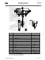
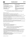
Pneumatic actuator 3f1
Operating instructions
B 3f1...E
Page 1 of 2
Disassembly of actuator:
Assembly of actuator:
- Move actuator with actuating pressure into
the middle of the stroke
- Loosen headless setscrew in the cap nut (21)
- Secure coupling (20) position (width across
flats 32), unscrew** cap nut (21)
- Unscrew nut (23)
- Remove actuator from valve
- Let off actuating pressure
- Position actuator onto valve, tighten nut (23)
- Move actuator into middle of stroke with
actuating pressure
- Secure coupling (20) position (width across
flats 32)
- Tighten cap nut (21) and headless setscrew
- Move valve into end positions, if necessary,
and adjust clamping rings towards position
indicator (17)
** Note: Ensure that the position of coupling (20), indicating plate (19) and fastening nut (18)
is not altered, otherwise the starting point of the actuator will require resetting.
Setting the starting point
Ensure that the actuator is readily assembled on the valve before setting.
Release lock nut (18) (see fig. 1) on the actuator spindle (16) and screw slightly in the direction of the
actuator. Temporarily remove the indicating plate (19) located beneath.
Set the desired starting pressure for the actuator on the control air reducing unit. If the access is performed
via a positioner, set it to the maximum actuating pressure by the appropriate input signal.
Screw coupling (20) onto the actuator spindle (16) until the valve spindle is just in the CLOSED position
or starts moving in the OPEN direction.
If the coupling cannot be adjusted sufficiently on the drive spindle, first of all adjust the coupling ring (22)
by approx. 5 mm. It is accessible after the cap nut (21) has been screwed off the coupling (20) and can be
turned slightly up or down on the spindle.
First of all loosen the headless setscrews of the position securing element on the coupling ring and cap nut.
After completing the measure, ensure that all parts are restored to their original status.
Subsequently, reattach indicating plate (19), secure with lock nut (18) and restore to the normal operating
status on the pressure reducing unit or positioner.
Exchanging the diaphragms
- Dismantle actuator from valve - as described above
- Unscrew coupling (20) and nut (18) from the drive spindle (16)
- Remove nuts and screws (5) and diaphragm lid (1)
Attention: All actuators contain two long screws. Ensure that these screws are loosened last
and uniformly on both sides to reduce the spring pretension / preloading.
Non-observance of this information entails risk of injury !
- Remove springs (2) and spindle-diaphragm-diaphragm plate unit
- Secure spindle (16) position (width over flats 13) and screw off screw (4) together with retaining ring
- Remove clamping element (3) and diaphragm (8), insert new diaphragm (8) and clamping element (3)
- Replace retaining ring, insert screw (4) and tighten against the spindle (16)
- Insert springs (2) and spindle-diaphragm-diaphragm plate unit, ensuring at the same time that the
springs are correctly positioned in the diaphragm plate (6) and the diaphragm is aligned in relation
to the screw holes
- Put diaphragm lid (1) in place and align, insert screws (5) commencing with the two long screws
and tighten in a cross pattern with the nuts
- Screw coupling (20) and nut (18) onto the actuator spindle (16), insert indicating plate (19)
- Mount actuator onto valve - as described above
- Set the starting point - as described above
data subject to alteration
3F1-B-1E.DOC / 0103505
Pneumatic actuator 3f1
Operating instructions
B 3f1...E
Page 2 of 2
01
02
03
04
05
06
07
08
09
10
11
12
13
14
15
16
17
18
Detail X
20
21
22
19
20
21
22
23
X
Fig. 1
No.
01
02
03
04
05
06
07
08
09
10
11
12
13
14
15
16
17
18
19
20
21
22
23
Designation
Diaphragm lid
Spring
Clamping element
Screw M12 with retaining ring
Screw M8 with Nut
Diaphragm plate
Diaphragm housing
Diaphragm
O-ring
Spindle guidance
Seeger-ring
Guiding tape
O-ring
Bellow
Mounting rod
Spindle
Stroke indikators
Nut M12
Indicating plate
Coupling
Cap nut
Coupling ring with headless setscrew
Nut M16 with spring ring
Part-No.
f5h
f5f ***
f3ks
e8av1230+f8ds12
f8av0825+f8mv08
f5mt
f5b
f5m
f5o38x4
f3sd
f5sr31
f9fb
f5o18x3
f5gf
f3s200
f3s12
e5ak
f8mv12f
f3ab
f3k60
f3um3/4
e3sr10 ****
e8mv16+e8fv16
*** = Stroke and control pressure dependent
**** = Only for valve spindle with thread M10
data subject to alteration
3F1-B-2E.DOC / 0103505