1
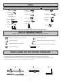
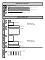
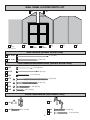
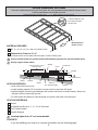
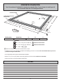
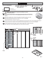
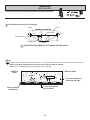
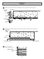
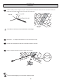
34/0
#ALL5S&IRST
$/./42%452.4/34/2%
&ORIMMEDIATEHELPWITHASSEMBLYORPRODUCTINFORMATION
CALLOURTOLLFREENUMBER
OREMAIL
CUSTOMERSERVICE BACKYARDPRODUCTSLLCCOM
/URSTAFFISREADYTOPROVIDEASSISTANCE
!PRILTHROUGH/CTOBER-&!-TO0-%34
3ATURDAY!-TO0-%34
.OVEMBERTHROUGH-ARCH-&!-TO0-%34
4HISPAGEINTENTIONALLYLEFTBLANK
ASSEMBLY MANUAL
16767
04/21/2011
A Backyard Products Company
MARCO SERIES
MAJESTIC 8' x 12' (244 x 366 cm)
ACTUAL FLOOR SIZE IS 96 x 144" (244 x 366 cm)
KEEP THIS MANUAL FOR FUTURE REFERENCE
IMPORTANT!
READ INSTRUCTIONS THOROUGHLY PRIOR TO BEGINNING ASSEMBLY.
BEFORE YOU BEGIN
• BUILDING RESTRICTIONS AND APPROVALS
Be sure to check with local building department and homeowners association for specic restrictions and/ or requirements before building
.
• ENGINEERED DRAWINGS
Contact our Customer Service Team if engineered drawings are needed to pull local permits.
• SURFACE PREPARATION
To ensure proper assembly you must build your shed on a level surface. Recommended methods and materials to level your shed are
listed on page 8.
• CHECK ALL PARTS
Inventory all parts listed on pages 4 - 6. Contact our Customer Service Team if any parts are missing or damaged.
• ADDITIONAL MATERIALS
You will need additional materials to complete your shed. See page 3 for required and optional materials and quantities.
- CUSTOMER SERVICE Call: 1-800-221-1849 email: [email protected]
TOOLS
Required
❑ Phillips
Optional
❑ Tool Belt/
❑ Utility Knife
Screwdriver
Nail Pouch
❑ Shingle Blades
❑ Drill / Driver
❑ 1/4" Drill Bit
❑ 3/8" Drill Bit
❑ 1/2" Drill Bit
❑ #2 Philips Drive Bit
❑ Tin Snips
❑ Caulk Gun
(for drip edge)
❑ Chalk Line
❑ Paint Tools
❑ Hammer
❑ Nail Gun
❑ Safety Glasses
❑ Level
❑ Pencil
❑ Ladder
❑ Tape Measure
❑ Square
• gun nails
❑ Gloves
or
Safety! Always use approved safety glasses during assembly.
HELPFUL REMINDER SYMBOLS
Look for these symbols for helpful reminders throughout this manual.
= Assistance Required; two or more people.
= Mark part with pencil.
= Ensure squareness.
BEGIN
= Important required step or operation.
FINISH = You have nished the assembly or installation.
= Helpful assembly hint.
= Beginning of steps for assembly or installation.
= Level
ORIENT LUMBER AND TRIM FOR BEST APPEARANCE
Framing lumber is graded for structural strength and not appearance. Exterior trim is graded for one good side.
Always install the material leaving the best edge and best surface visible. Please remember that these blemishes in no way
negatively affect the strength or integrity of our product. (See Fig. A, B, C.)
A
B
2
C
ADDITIONAL MATERIALS
FOUNDATION OR FLOOR MATERIALS
• This shed kit includes a complete wood oor frame system. It does not include any oor panels.
• See page 7 for the additional Áoor panel sizes and quantities required.
• This shed kit does not include ANY leveling materials.
• See the FLOOR LEVELING section on page 8 for recommended methods and suggested materials to properly level your
Áoor, as this will vary depending on your speciÀc site.
REINFORCED WOOD FLOOR FRAME (OPTIONAL)
IMPORTANT! The included oor has been designed for general use. Depending on your specic use you may want to construct a
heavy duty oor frame by adding additional oor joists (shown below as shaded). Below is a list of additional materials (not included):
x6 2 x 4 x 8' (5 x 10 x 244 cm) Treated Lumber
Cut to (6) 2 x 4 x 93" (5 x 10 x 236 cm)
x24 ea. 3" (7,6 cm) Hot Dipped Galvanized Nails
Optional 12" (30,5 cm) spacing
Standard 24" (61 cm) spacing
COMPLETING YOUR SHED
You will need these additional materials:
3-TAB SHINGLES ............................ 5 Bundles
1" GALVANIZED ROOFING NAILS.... 3 Lbs
For shingles.
PAINT FOR SIDING .......................... 2 Gallons
PAINT FOR TRIM .............................1 Quart
Use 100% acrylic latex exterior paint. (2) coats recommended.
Use 100% acrylic latex exterior paint.
CAULK ................................................. 3 Tubes
WOOD GLUE ....................... Exterior Rated
Use acrylic latex exterior caulk that is paintable.
OPTIONAL MATERIALS
DRIP EDGE ..................... 50 Feet
#15 ROOFING FELT
To cover 122 Sq. Ft. of roof area.
1" GALVANIZED ROOFING NAILS.........1/4 Lb
For roong felt.
REFER TO THE BACK OF THIS MANUAL AND THE MANUFACTURER’S INSTRUCTIONS
FOR INSTALLATION OF SHINGLES, DRIP EDGE AND FELT.
3
PARTS IDENTIFICATION AND SIZES
Part identication
letters are stamped on some parts.
Treated lumber is stamped:
WOOD SIZE CONVERSION CHART
Nominal Board Size
Actual Size
2" x 4"..............1-1/2" x 3-1/2" (3,8 x 8,9 cm)
RS
1" x 4".................3/4" x 3-1/2" (1,9 x 8,9 cm)
RS
2" x 3"..............1-1/2" x 2-1/2" (3,8 x 6,3 cm)
Check these locations for
part stamp.
1" x 3".................3/4" x 2-1/2" (3,8 x 6,3 cm)
PARTS LIST
TRIM
RAFTERS
WALLS
FLOOR
INVENTORY YOUR PARTS before you begin.
We suggest sorting parts by the category they are listed in.
x2
All treated lumber
is stamped:
2 x 4 x 48" (5 x 10 x 122 cm)
x7
2 x 4 x 93" (5 x 10 x 236 cm)
x2
2 x 4 x 96" (5 x 10 x 244 cm)
3/4" (1,9 cm)
x1
GAA
x1
NA
2 x 3 x 9" (5 x 7,6 x 23 cm)
x1
DI
1 x 3 x 12" (2,5 x 7,6 x 30,5 cm)
x2
RK
2 x 3 x 13" (5 x 7,6 x 33 cm)
x1
FR
x1
AQ
x2
FS
2 x 3 x 35-1/4 " (5 x 7,6 x 89,5 cm)
x4
NK
2 x 3 x 48" (5 x 7,6 x 122 cm)
x1
UX
x14
FU
x2
FV
2 x 3 x 82-1/2" (5 x 7,6 x 210 cm)
x1
FW
2 x 3 x 84" (5 x 7,6 x 213 cm)
x2
PS
x4
PT
x10
1 x 3 x 5" (2,5 x 7,6 x 12,7 cm)
GAUGE BLOCK FOR 3/4" (1,9 CM) MEASUREMENT.
2 x 3 x 23" (5 x 7,6 x 58 cm)
2 x 3 x 31" (5 x 7,6 x 79 cm)
2 x 4 x 64" (5 x 10 x 162,5 cm)
2 x 3 x 78-1/2" (5 x 7,6 x 199 cm)
2 x 3 x 91" (5 x 7,6 x 231 cm)
2 x 3 x 96" (5 x 7,6 x 244 cm)
6 x 23-1/4" (15 x 59 cm)
x10
AA
x3
JF
x3
EY
x2
AW
x2
AN
x4
AG
x2
ZJ
2 x 4 x 55-3/16" (5 x 10 x 140 cm)
1 x 4 x 60" (2,5 x 10 x 152 cm)
5/8 x 2-1/2 x 9" (1,6 x 6,3 x 23 cm)
2 x 3 x 41-7/8" (5 x 7,6 x 106 cm)
2 x 4 x 48-3/4" (5 x 10 x 124 cm)
2 x 4 x 59-1/8" (5 x 10 x 150 cm)
5/8 x 2-1/2 x 72" (1,6 x 6,3 x 183 cm)
3/8 x 1-3/4 x 82-1/4" (0,9 x 4,4 x 209 cm)
x10
x4
x2
2 x 2 x 84" (5 x 5 x 213 cm)
TP
METAL CORNER TRIM
2 x 4 x 96" (5 x 10 x 244 cm)
4
DOOR
SHELF
PARTS LIST continued...
x1
FQ
x5
PT
2 x 3 x 96" (5 x 7,6 x 244 cm)
x2
TP
2 x 4 x 96" (5 x 10 x 244 cm)
x2
2 x 3 x 28-5/8" (5 x 7,6 x 73 cm)
OO
2 x 3 x 69" (5 x 7,6 x 175,3 cm)
PANEL PARTS LIST
NOTE: Panel parts are not stamped.
ROOF PANELS
x4
x4
SHELF PANELS
7/16 x 25-3/4 x 48"
(1,1 x 65,4 x 122 cm)
Roof panels are
7/16" (1,1 cm) thick.
x2
7/16 x 11-1/4 x 96"
(1,1 x 29 x 244 cm)
x2
7/16 x 48 x 96"
(1,1 x 122 x 244 cm)
x2
7/16 x 44-1/4 x 48"
(1,1 x 112 x 122 cm)
Shelf panels are
7/16" (1,1 cm) thick.
x1
x2
WINDOW
7/16 x 11-1/4 x 25-3/4"
(1,1 x 29 x 65,4 cm)
x2
7/16 x 23-7/8 x 91"
(1,1 x 61 x 231 cm)
7/16 x 11-7/8 x 96"
(1,1 x 30 x 244 cm)
10-1/2 x 32-1/2"
(27 x 82,5 cm)
5
WALL PANEL & DOORS PARTS LIST
x2
x6
x1
3/8 x 48 x 84"
(1 x 122 x 213 cm)
x2
x1
x1
x1
LEFT DOOR
RIGHT DOOR
x1
x1
NAIL BOXES (Shown Actual Size)
x3
BOXES
x4
BOXES
3" (7,6 cm)
2" (5,0 cm)
FASTENER/HARDWARE BAG (Shown Actual Size)
113
1-1/2" (3,8 cm)
x110
2" (5,0 cm)
x64
1-1/4" (3,2 cm)
x70
3" (7,6 cm)
x20
2" (5,0 cm)
x96
x48
1-1/4" (3,2 cm)
3/4" (1,9 cm)
DOOR HARDWARE (Not Actual Size)
x1
x2
x6
x2
3/4" (1,9 cm)
x2
6
1" (2,5 cm)
1-1/4" (3,2 cm)
FLOOR PANELS (Not Included)
You will need oor panels and nails to complete your oor. Floor panel sizes and
quantities are shown below.
NOTE: Use a minimum of 5/8" (1,6 cm) oriented strand board (OSB).
5/8 x 48 x 96"
(1,6 x 122 x 244 cm)
x3
x1
1 lb. of 2" (5,0 cm) Hot Dipped Galvanized Box-Type Nails
2" (5,0 cm)
NOTES
7
FLOOR LEVELING OPTIONS
There are multiple ways to level your oor frame. Our recommended leveling method is shown below.
Leveling materials are not included in this kit.
PREFERRED METHOD - 4x4 TREATED RUNNERS
• 3" Screws angled into 4x4.
• (2) at each point frame
• and 4x4 touch.
12"
(30,5 cm)
O
O
R
Measurements to
centers of 4x4's.
D
MATERIAL REQUIRED
12"
(30,5 cm)
x2 4" x 4" x 12' (10 x 10 x 366 cm)Treated Lumber
Fasteners for Frame to 4"x 4".
(3" Screws shown as one option.) Minimum (28) 3" screws / exterior grade.
Use only wood treated for ground contact and fasteners approved for use with treated wood.
Always support frame seams.
Maximum between leveling
material locations.
Shingle
4x4 Runner
Level
48"
12"
12"
Shingle
Do not exceed 16".
Gravel
LEVELING METHODS
2" Block
Gravel
4" Block
2x4 Treated Lumber
8" Block
• Level under 4x4 runners only.
• Locate leveling material 12" from ends of runners and no more than 48" apart.
• Asphalt shingles should be used between 4x4 runners and blocks or treated lumber. Never use
shingles in direct contact with ground.
• For best results and aiding in water drainage use gravel under each concrete block.
LEVELING MATERIALS
Gravel
Solid Masonry Blocks in 1", 2", 4" or 8" thickness
2x4 Treated Lumber
Asphalt Shingles
Leveling higher than 16" not recommended.
CONCRETE
• If you are building your shed on a concrete foundation see the following page.
8
CONCRETE FOUNDATION
Your kit contains all materials to construct a wooden oor. If you choose to install your kit
on a concrete slab refer to the diagram below.
Treated Sill Plate
Caulk between sill plate
and concrete.
3-1/2"
(8,9 cm)
B
C
A
DOO
R
Building Size
8'x 12' (244 x 366 cm)
4"
(10 cm)
Actual Size
96" x 144" (244 x 366 cm)
A
B
96" (244 cm)
137" (345 cm)
C
144" (366 cm)
Requires:
x2 2" x 4" x 12' (5 x 10 x 366 cm)
MUST be treated lumber.
x2 2" x 4" x 8' (5 x 10 x 244 cm)
MUST be treated lumber.
x1 Caulk
Allow new concrete slabs to cure for at least seven (7) days.
• A treated 2 x 4" (5 x 10 cm) sill plate is required when installing your shed on concrete. Hint: Use treated lumber in your kit or
purchase full length treated lumber.
• Use a high quality exterior grade caulk beneath all sill plates.
• Fasten 2 x 4" (5 x 10 cm) sill plates to slab using approved concrete anchors (fasteners not included).
• Check local code for concrete foundation requirements.
NOTES
9
FLOOR FRAME
PARTS REQUIRED:
x2
3" (7,6 cm) x32
2 x 4 x 96" (5 x 10 x 244 cm)
Look for
x7
TREATED
2 x 4 x 93" (5 x 10 x 236 cm)
x2
Stamp
2 x 4 x 48" (5 x 10 x 122 cm)
BEGIN
1
Orient parts as shown on at surface. Measure and mark.
2
Use two 3" nails at each mark.
FINISH
3
OR
DO
You have nished your oor frame. Proceed to level and square frame.
HINT:
For easier nailing
stand on frame.
144"
(366 cm)
120"
(305 cm)
96"
(244 cm)
72"
(183 cm)
48"
(122 cm)
96"
(244 cm)
24"
(61 cm
Flush
Offset
Seam
Center
on marks
96"
(244 cm)
93"
(236 cm)
Offset
Seam
48"
(122 cm)
96"
(244 cm)
10
Flush
LEVEL AND SQUARE FLOOR FRAME
Before attaching oor decking, it is important to level and square the oor frame.
A level and square oor frame is required to correctly construct your shed.
BEGIN
1
See page 8 for the preferred oor leveling method.
2
Use level and check the frame is level before applying oor panels.
3
Check for frame squareness by measuring diagonally across corners. If the measurements are the
same, the frame is square. The diagonal measurement will be approximately 173-1/16" (440 cm).
4
When the frame is level and square secure one side of frame to the 4x4 runners using one fastener at
ends of each runner. Move to the opposite end of the frame. Secure the frame to 4x4 runners with one
fastener at ends of each runner making sure the frame remains square (Fig. A).
FINISH
5
Once the oor frame is level and square fasten the frame to the 4x4 runners at each point the frame
contacts the 4x4 runners.
First, secure
at ends with
one fastener.
Fig. A
173-1/16"
(440 cm)
173-1/16"
(440 cm)
R
O
DO
Second, secure
at ends with
one fastener.
11
FLOOR PANELS
PARTS REQUIRED:
FLOOR PANELS NOT INCLUDED. SEE
PAGE 7 FOR PANEL SIZES
AND QUANTITIES.
2" (5 cm) x55
5/8 x 48 x 96"
(1,6 x 122 x 244 cm)
x1
Ensure your Áoor frame is square by installing one panel
and squaring frame.
BEGIN
1 Attach the 48 x 96" panel with the rough side up (painted-grid lines side) with the 48"
edge and corner ush to the oor frame (Fig A). Secure panel with two 2" nails in the
corners.
2
Move to the opposite side. Using the long edge of the panel as a lever, move the
panel side-to-side until the top corner is ush to the oor frame (Fig. B).
Secure panel with two 2" nails in the corners.
OR
DO
3
Check the oor frame is square by measuring diagonally across the frame corners. If the measurements are the
same your oor frame is square. The measurement will be approximately 173-1/16" (440 cm) (Fig. C).
4
Continue attaching the panel using 2" nails 6" apart on edges and 12" apart inside panel.
Use a chalk line or use pre-painted grid lines to nail into joists under panel.
48"
(122 cm)
144"
(366 cm)
3/4"
(1,9 cm)
Grid lines up
Fig. A
Flush
(2) Nails
Flush
(2) Nails
12" (30 cm)
Fig. B
6"
(15 cm)
Flush
173-1/16"
(440 cm
173-1/16"
(440 cm
Fig. C
12
FLOOR PANELS
PARTS REQUIRED:
2" (5 cm) x110
5/8 x 48 x 96"
(1,6 x 122 x 244 cm)
x2
5
Continue installing panels with rough side up
(painted grid lines).
76
Use grid lines on panel for 2" nails 6" apart on
edges, and 12" apart inside panels.
FINISH
7
OR
DO
You have nished attaching your oor panels.
Flush
144"
(366 cm)
48"
(122 cm)
48"
(122 cm)
Grid lines
up
12"
(30) cm
6"
(15 cm)
Flush
Flush
13
IMPORTANT!
DO
OR
Check the Áoor frame is level after installing Áoor panels.
Re-level if needed.
• The Áoor should used as a stable work surface for wall construction.
HINT:
• Organize your assembly procedure during the build process
to avoid over-handling of the walls.
Side Wall
D
O
O
R
Back wall
Side wall
Front wall
14
SIDE WALL FRAMES
PARTS REQUIRED:
x4
NK
x14
FU
x4
PT
3" (7,6 cm) x64
2 x 3 x 48" (5 x 7,6 x 122 cm)
2 x 3 x 78-1/2" (5 x 7,6 x 199 cm)
2 x 3 x 96" (5 x 7,6 x 244 cm)
BEGIN
1
Orient parts on edge on oor. Measure and mark.
IMPORTANT! You will build two walls the same.
2
Use two 3" nails at each mark.
OR
DO
HINT:
For easier nailing
stand on frame.
144”
(366 cm)
120”
(305 cm)
96”
(244 cm)
48”
(122 cm)
72”
(183 cm)
48”
(122 cm)
24”
(61 cm)
Offset Seam
NK
PT
FU x7
TOENAILING
78-1/2”
(199 cm)
48”
(122 cm)
Offset Seam
96”
(244 cm)
PT
NK
15
SIDE WALL PANELS
PARTS REQUIRED:
GAA
48 x 84"
122 x 213 cm)
x1
x1
2" (5 cm) x45
RK
2 x 3 x 13" (5 x 7,6 x 33 cm) as SPACER
3/4" GAUGE
BLOCK
Ensure your wall frame is square by installing one panel and
squaring frame.
3
Place the 48 x 84" panel onto wall frame with primed side up as shown.
Use the gauge block to mark the 3/4" measurement on the wall stud.
Use RK as a 1-1/2" gauge block at top. Secure panel with two 2" nails in
the corners (Fig. A).
4
Move to the opposite end. Using the long edge of the panel as a lever
move the panel side-to-side until you have a 3/4" measurement on the
wall stud. Secure corner with two 2" nails (Fig. B).
5
Nail the panel using 2" nails 6" apart on edges and 12" apart inside panel.
OR
DO
For squareness, maintain 3/4" and
1-1/2" measurement along panel edges.
BEGIN HERE
2 Nails
HINT: Use RK
as 1-1/2" gauge
3/4"
(1,9 cm) 1-1/2"
(3,8 cm)
1-1/2"
(3,8 cm)
3/4"
(1,9 cm)
Primed side up
12"
(30) cm
Fig. A
6"
(15 cm)
1-1/2"
(3,8 cm)
3/4"
GAUGE
BLOCK
3/4"
(1,9 cm)
48"
(122 cm)
3/4"
(1,9 cm)
Fig. B
2 Nails
16
SIDE WALL PANELS
PARTS REQUIRED:
2" (5 cm) x90
GAA
48 x 84"
122 x 213 cm)
x2
x1
6
RK
3/4" GAUGE
BLOCK
2 x 3 x 13" (5 x 7,6 x 33 cm) as SPACER
Place center 48" panel on frame as
shown with primed side facing up.
For squareness maintain
Áush and 1-1/2" measurement
along panel edges.
Nail using 2" nails 6" apart on edges
and 12" apart inside panel.
Flush
OR
DO
3/4"
(19 mm)
HINT:
Use RK as
1-1/2" gauge
1-1/2"
(3,8 cm)
Primed
side up
12"
(30 cm)
6"
(15 cm)
48"
(122 cm)
7
Place end 48" panel on frame as shown
with primed side facing up.
For squareness maintain Áush and
1-1/2" measurement along panel edges.
Flush
Nail using 2" nails 6" apart on edges
and 12" apart inside panel.
1-1/2"
(3,8 cm)
HINT:
Use RK as
1-1/2" gauge
12"
(30 cm)
6"
(15 cm)
Primed
side up
OR
DO
8
48"
(122 cm)
Carefully ip the sidewall over.
Repeat STEPS 1-8 to assemble your
second side wall.
FINISH
9
You have nished building both your sidewalls.
17
BACK WALL
PARTS REQUIRED:
x1
48 x 96"
(122 x 244 cm)
x1
RK
1-1/2" (3,8 cm) x11
2 x 3 x 13" (5 x 7,6 x 33 cm)
x1
FS
2 x 3 x 35-1/4" (5 x 7,6 x 89,5 cm)
x2
PS
2 x 3 x 91" (5 x 7,6 x 231 cm)
BEGIN
1
Orient parts on at on oor as shown.
2
Place panel on FS and PS with primed side up.
3
Nail FS rst, 1" (2,5 cm) from panel bottom.
OR
DO
Use 1-1/2" nails only 6" (15 cm) apart.
4
Place PS ush to FS. Hold the 36-1/4" (92 cm) measurement and nail with
1-1/2" nails 12" (30 cm) apart.
Primed side
UP
PS
temporary support
Use only 1-1/2"
(3,8 cm) long nails
PS
2-1/2"
(6,3 cm)
Flush
FS
36-1/4"
(92 cm)
1-1/4"
(3,2 cm)
2-1/2"
(6,3 cm)
RK
1"
(2,5 cm)
temporary support
18
36-1/4"
(92 cm)
BACK WALL
PARTS REQUIRED:
x1
x1
x1
AQ
1-1/2" (3,8 cm) x15
FS
2 x 3 x 35-1/4" (5 x 7,6 x 89,5 cm)
2 x 3 x 31" (5 x 7,6 x 79 cm)
x1
TEMPORARY SUPPORT
EY
5/8 x 3 x 9" (1,6 x 7,6 x 23 cm)
PS
2 x 3 x 91" (5 x 7,6 x 231 cm)
5
Orient parts on at beneath panel as shown.
6
Place the EY 5/8" (1,6 cm) spacer on the lower PS. Place FS ush to spacer and nail.
Use 1-1/2" (3,8 cm) nails only 6" (15 cm) apart.
7
Place PS ush to FS. Hold the 74-5/8" (189,5 cm) measurement and
nail with 1-1/2" (3,8 cm) nails 12" (30 cm) apart.
8
Orient AQ on at and beneath panel as shown.
9
Place AQ ush to EY spacer and nail.
Use 1-1/2" (3,8 cm) nails only 6" (15 cm) apart.
AQ
2-1/2"
(6,3 cm)
OR
DO
2-1/2" (6,4 cm)
44-1/4"
(112 cm)
44-1/4"
(112 cm)
1-1/4" (3,2 cm)
EY
Use as spacer.
Flush
5/8"
(1,6 cm)
2-1/2"
(6,3 cm)
PS
Flush
FS
1-1/4"
(3,2 cm)
74-5/8"
(189,5 cm)
EY
2-1/2"
(6,3 cm)
74-5/8"
(189,5 cm)
Use as spacer.
Flush
5/8"
(1,6 cm)
PS
RK
temporary support
19
BACK WALL
PARTS REQUIRED:
x1
1-1/2" (3,8 cm) x26
RK
2 x 3 x 13" (5 x 7,6 x 33 cm)
48 x 96"
(122 x 244 cm)
x1
10
Place right panel onto frame primed side up.
11
Nail using 1-1/2" nails 6" (15 cm) apart on edges,
and 12" apart inside panel.
OR
DO
Primed side
UP.
Flush
6"
(15 cm)
74-5/8"
(189,5 cm)
12"
(30,5 cm)
36-1/4"
(92 cm)
Flush
1"
(2,5 cm)
RK
temporary support
20
BACK WALL
PARTS REQUIRED:
x1
RK
2 x 3 x 13" (5 x 7,6 x 33 cm)
x1
3/8 x 12 x 24"
(1 x 30,5 x 61 cm)
x1
3/8 x 12 x 24"
(1 x 30,5 x 61 cm)
1-1/2" (3,8 cm) x12
12
Nail left and right 12 x 24" (30,5 x 61 cm) panels primed side up using three 1-1/2" nails.
13
Nail RK on edge at each location using three 1-1/2" nails (Fig. A).
FINISH
14
You have nished your back wall.
OR
DO
Flush
Primed side
UP.
Line up seams.
2-1/2"
(6,4 cm)
RK
Fig. A
1"
(2,5 cm)
RK
RK
2-1/2"
(6,3 cm)
1-1/2"
(3,8 cm)
1-1/2"
(3,8 cm)
21
2-1/2"
(6,3 cm)
FRONT WALL FRAME
PARTS REQUIRED:
x1
2" (5 cm) x6
UX
2 x 4 x 64" (5 x 10 x 162,5 cm)
x1
NA
2 x 3 x 9" (5 x 7,6 x 23 cm)
x1
DI
1 x 3 x 12" (2,5 x 7,6 x 30,5 cm)
BEGIN
1
Orient NA and UX on at on oor as shown.
2
Orient DI on at on top of NA ush to top (Fig A.).
3
Nail DI to NA and UX using (6) 2" nails as shown.
OR
DO
32"
(77,5 cm)
32"
(77,5 cm)
NA
2-1/2"
(6,3 cm)
UX
3-1/2"
(8,9 cm)
Flush
Flush to TOP
DI
Fig. A
32"
(77,5 cm)
32"
(77,5 cm)
2-1/2"
(6,3 cm)
22
FRONT WALL FRAME
PARTS REQUIRED:
x2
3" (7,6 cm) x8
FV
2 x 3 x 82-1/2" (5 x 7,6 x 210 cm)
x1
FW
2 x 3 x 84" (5 x 7,6 x 213 cm)
x1
Temporary
Support
Pre-Assembled
7/16 x 25-3/4 x 48"
(1,1 x 65,4 x 122 cm)
BEGIN
1
Orient parts on edge on oor as shown. Install FW to studs with 3" nails (Fig. A).
2
Place one roof panel as temporary support under pre-assembled frame.
3
Orient Pre-Assembled Frame on at,
DI facing down. Position Frame 9" from
bottom of FW. Install Frame to studs using (2) 3" nails (Fig. B)
OR
DO
(2) 3" (10 cm)
Nails
2-1/2"
(6,3 cm)
84"
(213 cm)
10"
(23 cm)
64"
(162,5 cm)
FW
10"
(23 cm)
1-1/2"
(3,2 cm)
Fig. A
9"
(23 cm)
9"
(23 cm)
(2) 3" (10 cm)
Nails
3-1/2"
(9 cm)
Pre-Assembled
Temporary
Support
DI facing down
Flush
Fig. B
3-1/2"
(9 cm)
2-1/2"
(6,4 cm)
82-1/2"
(210 cm)
FV
FV
3-1/2"
(9 cm)
1-1/2"
(3,2 cm)
1-1/2"
(3,2 cm)
23
FRONT WALL FRAME
Temporary
Support
PARTS REQUIRED:
x1
x3
FR
3" (7,6 cm) x2
2 x 3 x 23" (5 x 7,6 x 58 cm)
3" (7,6 cm) x2
7/16 x 25-3/4 x 48"
(1,1 x 65,4 x 122 cm)
4
Secure NA with (2) 3" nails (Fig. A).
5
Place two roof panels as temporary supports above frame. Install FR centered as
shown with (2) 3" screws (Fig. B).
Leave temporary supports in place until after front panels are installed.
OR
DO
FINISH
6
You have nished your front wall frame.
Fig. A
(2) 3" (10 cm)
Nails
Flush
NA
Temporary
Support
2-1/2"
(6,3 cm)
Fig. B
(2) 3" (10 cm)
Screws
2-1/2"
(6,3 cm)
Flush
FR
42"
(106,7 cm)
42"
(106,7 cm)
24
FRONT WALL PANELS
PARTS REQUIRED:
1-1/2" (3,8 cm) x24
x1
Handle panels with care to avoid breakage.
BEGIN
1
2
Place left panel on front wall frame with primed side up as shown.
Hold the 1-1/4" and 1/4" measurement.
1-1/4"
(3,2 cm)
Nail with 1-1/2" nails 6" (15 cm) apart. Maintain 64" (162,5 cm)
measurement between studs and square frame.
OR
DO
Temporary
Supports
1-1/4" (3,2 cm)
Primed side UP
3-1/2"
(9 cm)
12"
(30,5 cm)
1/4" (0,6 cm) BELOW PANEL
1-1/4"
(3,2 cm)
HANDLE WITH CARE TO PREVENT
BREAKING AT CORNERS.
HOLD MEASUREMENT
6"
(15 cm)
MAINTAIN MEASUREMENT BETWEEN
STUDS.
64"
(162,5 cm)
25
FRONT WALL PANELS
PARTS REQUIRED:
x1
x1
12 x 24"
(30,5 x 61 cm)
x1
12 x 24"
(30,5 x 61 cm)
1-1/2" (3,8 cm) x30
3
Place right panel on front wall frame with primed side up as shown.
4
Nail with 1-1/2" nails 6" (15 cm) apart.
Maintain 64" (162,5 cm) measurement between studs and square frame.
5
Place right and left 12 x 24" (31 x 61 cm) panels on front wall frame with primed
side up as shown. Nail with 1-1/2" nails 6" (15 cm) apart.
OR
DO
FINISH
6
You have nished your front wall.
Flush
Temporary
Supports
Primed side
UP
Line up seams.
12"
(30,5 cm)
1/4" (0,6 cm)
BELOW PANEL
Flush
HANDLE WITH CARE TO PREVENT BREAKING
AT CORNERS.
6"
(15 cm)
MAINTAIN MEASUREMENT BETWEEN
STUDS.
64"
(162,5 cm)
26
BACK WALL INSTALLATION
PARTS REQUIRED (TEMPORARY):
x1
3" (7,6 cm) x6
PT
2 x 3 x 96" (5 x 7,6 x 244 cm)
3" (7,6 cm) x4
2" (5 cm) x18
BEGIN
1
Center back wall assembly on the 96" (244 cm) oor dimension.
2
Use PT as a temporary brace. Secure with two 3" screws.
2 x 3 x 96" (5 x 7,6 x 244 cm)
OR
DO
3" (7,6 cm)
Screws
96"cm)
4
(24
PT
3
First, nail lower edge of panel to oor frame using 2" nails 6" apart.
Angle nail to hit oor frame (Fig. A).
4
Attach RK, using three 3" (7,6 cm) nails as shown.
Angle nails to hit oor frame (Fig. A).
5
Secure back wall upright to oor using two 3" screws (Fig. B).
Nail 2" nails Àrst.
Angle to nail into
Áoor frame.
3" (7,6 cm)
Screw
2" (5 cm) Nail
3" (7,6 cm) Nail
Fig. B
Fig. A
FINISH
6
You have nished standing your back wall.
27
SIDE WALLS INSTALLATION
3" (7,6 cm) x24
3" (7,6 cm) x4
2" (5 cm) x39
BEGIN
Stand right sidewall on oor.
It is important to secure the sidewall in the following order.
1
Center sidewall on oor front to back.
Nail the lower backwall corner to the
sidewall frame with one 2" nail
(Fig. A).
DO
OR
2" (5 cm)
Nail
DOOR
Fig. A
CENTER
2" (5 cm)
Nail
2
Be sure the measurement between
the panel edges is the same along the
entire length. Then secure with one 2"
nail in the upper corner (Fig. B).
SAME
MEASUREMENT
Fig. B
6"
(15 cm)
Nail along the backwall panel edge into
the sidewall stud using 2" nails spaced
6" apart.
Nail along bottom of panel using
2" nails 6" apart. Angle nail to hit oor
frame (Fig. C).
6"
(15 cm)
Fig. C
Nail down the bottom plate using two 3" nails
between the wall studs.
3
Secure backwall horizontal supports with 3" screws
(Fig. E, F) into sidewall corner stud.
Remove temporary brace.
Repeat process to secure the left sidewall.
Fig. E
3" (7,6 cm)
Nail
DO
Fig. F
OR
FINISH
4
You have nished standing your side walls.
28
3" (7,6 cm)
Screw
FRONT WALL INSTALLATION
3" (7,6 cm) x2
3" (7,6 cm) x4
2" (5 cm) x30
BEGIN
Stand frontwall on oor.
It is important to secure the frontwall in the following order.
1
Center frontwall on oor side-to-side.
OR
DO
Nail the frontwall ush to the oor
using 2" nails 6" apart. Angle nails to
hit oor frame (Fig. A).
Nail the lower frontwall corner to the
sidewall stud with one 2" nail (Fig. B).
Fig. B
2" (5 cm)
Nail
Fig. A
2" (5 cm)
Nail
6"
6"
(15 cm)
(15 cm)
CENTER
2" (5 cm)
Nail
2
Be sure the measurement between the panel
edges is the same along the entire length.
Then secure with one 2" nail in the upper
corner (Fig. C).
SAME
MEASUREMENT
6"
(15 cm)
Fig. C
Nail along the panel edge into the sidewall stud
using 2" nails spaced 6" apart.
3
Secure the frontwall frame using two
3" screws (Fig. D).
Repeat process to secure the right side of
the frontwall.
(2) 3" (7,6 cm)
Screws
FINISH
4
You have nished standing your front wall.
Fig. D
29
LOFT FRAME
PARTS REQUIRED:
x2
3" (7,6 cm) x8
TP
2 x 4 x 96" (5 x 10 x 244 cm)
BEGIN
1
Measure the top of back wall loft support to oor. Measure and mark the same
measurement on the back side of sidewall studs at each side as shown.
2
Install one TP level against back side of studs at mark with two 3" nails at each end.
OR
DO
3
Repeat steps 1 - 2 to install second TP.
FINISH
4
You have nished installing your loft frame.
Mark
Mark
TP
Loft
Support
SAME MEASUREMENT
FLOOR
30
SHELF FRAME
PARTS REQUIRED:
3" (7,6 cm) x4
x1
PT
3" (7,6 cm) x8
2 x 3 x 96" (5 x 7,6 x 244 cm)
BEGIN
1
Place PT ush to top of loft support as shown (Fig A).
2
Install PT level against studs and with top edge of loft support. Secure PT with two
3" nails at each stud and at door side with two 3" screws.
OR
DO
Flush at top of
loft support.
Fig. A
(2) 3" (7,6 cm)
Screws at end only.
3" (7,6 cm)
Nails
Flush
(2) 3" (7,6 cm)
Nails
Loft
Support
NOTE: There will be a gap
at the end of PT.
DOOR
PT
LEFT SIDE
WALL
31
SHELF FRAME
PARTS REQUIRED:
3" (7,6 cm) x8
x1
PT
2 x 3 x 96" (5 x 7,6 x 244 cm)
Assistance may be required to install PT.
3
Place PT against loft support (Fig. A) and secure ush using two 3" screws.
4
Check PT for level and secure at front wall with two 3" screws.
OR
DO
FINISH
5
You have nished installing your left side shelf frame.
Repeat steps 1 through 4 on right side for second shelf frame.
Front Wall
Support
(2) 3" (7,6 cm)
Screws
(2) 3" (7,6 cm)
Screws
Loft
Support
PT
Flush
NOTE:
There will be a
gap at the end of PT.
Flush
Flush
LEFT SIDE
WALL
12"
(30,5 cm)
DOOR
Loft
Support
Fig. A
32
WORKBENCH
PARTS REQUIRED:
x1
3" (7,6 cm) x4
PT
2 x 3 x 96" (5 x 7,6 x 244 cm)
BEGIN
1
Measure the top of back wall workbench support from oor. Measure and mark the
same measurement on the back side of sidewall studs at each side as shown.
2
Install PT level against back side of studs at mark with two 3" nails at each
end.
OR
DO
Workbench Support
Mark stud.
Mark stud.
PT
SAME MEASUREMENT
FLOOR
33
WORKBENCH
PARTS REQUIRED:
x1
3" (7,6 cm) x4
FQ
2 x 3 x 28-5/8" (5 x 7,6 x 73 cm)
2" (5 cm) x20
7/16 x 23-7/8 x 91"
(1,1 x 61 x 231 cm)
x1
3
Place workbench into gap in back wall upright.
Secure with 2" nails, as shown.
OR
DO
Fit panel into gap.
23-7/8" (61 cm)
4
Attach FQ to upright and workbench, using four 3" (7,6 cm) screws as shown (Fig. A).
FINISH
5
Angle top screw
to hit FQ.
You have nished installing your workbench.
Flush
Fig. A
FQ
(4) 3" (7,6 cm)
Screws
Angle bottom screw
so it does not protrude
past panel.
34
LOFT PANELS
PARTS REQUIRED: x2
7/16 x 44-1/4 x 48"
(1,1 x 112 x 122 cm)
2" (5 cm) x8
BEGIN
1
Place loft panels onto the three loft supports centered from side-to-side
and ush with the back wall panel. Fit panels into gap.
2
IMPORTANT! Use only FOUR 2" nails in each panel, to allow squaring the roof.
You will complete nailing the loft panels later.
FINISH
3
You have temporarily nished your loft panels.
CENTER
Fit panels into gap.
Flush
44-1/4"
(112 cm)
44-1/4"
(112 cm)
Attention: Load not to exceed 250 lbs evenly
distributed across loft.
35
OR
DO
SHELF PANELS
PARTS REQUIRED:
2" (5 cm) x40
7/16 x 11-7/8 x 96"
(1,1 x 30 x 244 cm)
x2
BEGIN
1
Place shelf panel onto the left wall shelf frame. Shelf panel should be ush
against shelf support and loft panel. Attach using 2" nails, as shown.
2
Repeat on opposite side.
OR
DO
FINISH
3
You have nished installing your shelf panels.
Flush
LEFT WALL
Flush
LOFT AND SHELVING CAPACITY
Attention:
Load not to exceed 250 lbs
evenly distributed across loft.
Attention:
Load not to exceed 100 lbs
evenly distributed across shelf.
36
RAFTERS
PARTS REQUIRED:
x10
x10
AA
¸1
BEGIN
2
3
2" (5 cm) x120
6 x 24" (15 x 61 cm)
2 x 4 x 55-3/16" (5 x 10 x 140 cm)
You will build FIVE assemblies;
Place two rafter-halves in the corner of back and side walls.
Rafters should touch at peak. Apply glue on gusset and place on rafters.
Nail gusset onto rafter using 2" nails, staggered, as shown.
OR
DO
4
Flip over rafter assembly and glue and nail second gusset to back side.
5
Repeat steps 1-4 to build four more assemblies.
FINISH
6
You have nished assembling your rafters.
HINT:
Use Áoor and walls to help
assemble rafters!
96"
(244 cm)
Fit base of rafters in corners of back wall.
Temporary support (2x3)
Gap
1/4” (6 mm)
Touch at peak.
CENTER
AA
GLUE
96”
(244 cm)
37
AA
RAFTERS
PARTS REQUIRED:
3" (7,6 cm) x 20
¸1
2" (5 cm) x 10
Preassembled
x5
BEGIN
Locate rafters directly over studs and ush to wall panel.
Check that you have the measurements shown.
2
First, secure ends of rafters with one 2" screw at each end (Fig. A). Secure ends of
rafters with two 3" screw at each end (Fig. B, Fig. C).
3
Repeat steps to attach 4 rafters.
OR
DO
FINISH
4
You have attached your rafters.
MEASUREMENTS ARE FROM INSIDE OF PANELS.
MEASUREMENTS ARE TO CENTER OF RAFTERS.
24”
61 cm
24”
61 cm
24”
61 cm
24”
61 cm
24”
61 cm
24”
61 cm
Align over studs.
Maintain the measurements between rafters.
Fig. B
(2) 2" (5 cm)
Screws
each end.
Fig. C
(2) 3" (7,6 cm)
Screws
Flush
END VIEW
Fig. A
38
TRIM
PARTS REQUIRED:
1-1/4" (3,2 cm) x64
x4
2 x 2 x 84" (5 x 5 x 213 cm)
BEGIN
1
Install metal corner trim ush with top of side panel (Fig. A).
2
Secure trim to wall using sixteen 1-1/4" nails (eight per side) spaced evenly
as shown.
OR
FINISH
3
DO
You have nished installing your corner trim.
Trim is Áush with top of side wall panel.
Flush
Fig. A
39
GABLE TRIM
PARTS REQUIRED:
x4
AG
2 x 4 x 59-1/8" (5 x 10 x 150 cm)
Temporary
Straight Edge
OO
x1
2 x 3 x 69" (5 x 7,6 x 175,3 cm)
¸1
BEGIN
2
Orient AG on oor as shown. Using OO as a straight edge, mark a line
1-1/2" down length of AG (Fig. A).
Repeat step 1 to mark all trim.
OR
DO
1-1/2"
(3,8 cm)
Flush
Fig. A
Mark Line.
1-1/2"
(3,8 cm)
1-1/2"
(3,8 cm)
OO
40
GABLE TRIM
PARTS REQUIRED:
x4
1-1/4" (3,2 cm) x28
AG
2 x 4 x 59-1/8" (5 x 10 x 150 cm)
3
Position one AG 1-1/2" up from front panel edge and center with panel
seam (Fig. A). Attach trim with seven 1-1/4" screws from inside. Install two
screws at seam (Fig. B).
4
Position second AG 1-1/2" up from panel edge and ush to AG already attached (Fig. A). Attach trim with seven 1-1/4" screws from inside. Install two
screws at seam (Fig. B).
5
OR
DO
Repeat steps 3-4 to attach the back trim.
FINISH
6
You have attached your upper trim.
1-1/2"
(3,8 cm)
AG
HINT:
Clamp in position
before screwing.
Pre-marked
Line
Flush
Line up
seams.
1-1/2"
(3,8 cm)
Fig. B
Fig. A
) ly
cmate
8
(1 im
" ox
7 r
p
p
A
41
AG
GABLE TRIM
PARTS REQUIRED:
x2
1-1/4" (3,2 cm) x24
AW
2 x 3 x 41-7/8" (5 x 7,6 x 106 cm)
BEGIN
1
2
Install AW level over seam of front wall panels with twelve 1-1/4" screws from
inside as shown.
Repeat step 1 installing AW over seam at back side.
OR
DO
FINISH
3
You have nished installing your horizontal gable trim.
AW
AW
42
ROOF PANELS
PARTS REQUIRED:
x2
2" (5 cm) x4
x2
GAA
7/16 x 11-1/4 x 96"
(1,1 x 28,6 x 244 cm)
3/4"
GAUGE BLOCK
7/16 x 48 x 96"
(1,1 x 122 x 244 cm)
x2
x2
7/16 x 11-1/4 x 25-3/4"
(1,1 x 29 x 65,4 cm)
7/16 x 25-3/4 x 48"
(1,1 x 65,4 x 122 cm)
Roof panels may cause serious injury
until securely fastened.
You must square the roof by attaching one panel st. You will use the panels’ long
edge as a lever to bring your roof into square. Commonly known as “racking”.
OR
BEGIN
1
DO
Flush at peak.
Attach the 48 x 96" panel with the rough
side up (painted-grid lines side) with a 3/4"
measurement on the rafter (Fig A) and the
panel ush at the peak (Fig. B).
Two Nails
Fig. B
Secure panel with two 2" nails in
the corners.
(12 48"
2c
m)
3/4"
(1,9 cm)
Gauge
Block
Fig. A
Flush at peak.
2
Move to the opposite end. Using the long
edge of the panel as a lever move the
panel side-to-side until the top corner is
ush to the peak (Fig. C) and there is 3/4"
measurement to the rafter (Fig. D).
Fig. C
You may need to move your rafter to get
the 3/4" measurement. Secure panel with
two 2" nails in the corners.
Gauge
Block
3/4"
(1,9 cm)
43
Fig. D
ROOF PANELS
PARTS REQUIRED:
2" (5 cm) x174
GAA
3/4"
GAUGE BLOCK
3
Keep spacing between the center of the
rafters at the lower edge of the panel
and secure with one 2" nail into each
rafter (Fig. E).
Move to the top of the panel and keep
spacing between the center of the
rafters. Secure with one 2" nail into
each rafter (Fig. E).
OR
DO
6" (15 cm)
12"
(30,5 cm)
Nail the roof panel using 2" nails 6" apart
on edges and 12" apart inside panel.
Flush
Attach the second 11-1/4 x 96" lower
roof panel ush to rst panel along edge 7/16 x 11-1/4 x 96"
and with the 3/4" measurement (Fig. F). (1,1 x 28,6 x 244 cm)
Gauge
Block
3/4"
(1,9 cm)
4
Fig. F
NOTE: Measurements from inside of panels
At one end attach a lower 25-3/4 x 48" roof
panel ush to the center panels (Fig. G) and
with 1/8" at gable trim (Fig. H ).
22-1/4"
(56,5 cm)
24"
(61 cm)
24"
(61 cm)
24"
(61 cm)
24"
(61 cm)
Nail the roof panel using 2" nails 6" apart.
5
Attach one upper 11-1/4 x 25-3/4" roof panel
ush to the installed panel (Fig. G) and ush at
peak (Fig. H) and with 1/8" at gable trim (Fig. J).
Fig. E
2" Nail
1/8" (0,32 cm)
Gable
Trim
Nail the roof panels using 2" nails 6" apart.
Fig. J
Flush
Move to opposite end to install two more panels.
Repeat process to attach roof panels
on the opposite side.
Fig. H
11-1/4"
(28,6 cm)
48"
(122 cm)
OR
DO
Flush
FINISHYou
6
have nished installing
your roof panels.
Fig. G
3/4"
(1,9 mm)
44
3/4"
(1,9 mm)
22-1/4"
(56,5 cm)
COLLAR TIES
PARTS REQUIRED:
x3
2" (5 cm) x18
JF
1 x 4 x 60" (2,5 x 10 x 152 cm)
BEGIN
1
Position and level each JF on rst three rafters past door opening.
Do not install JF over loft.
HINT: For best appearance install JF on rafter facing away from door opening.
OR
DO
2
Glue JF and attach with 2" nails as shown.
FINISH
3
You have nished installiing your collar ties.
GLUE
GLUE
Flush
Flush
JF x3
45
LOFT PANELS
2" (5 cm) x22
BEGIN
1
Continue nailing 2" nails in each loft panel as shown.
FINISH
2
OR
DO
You have nished your loft panels.
Attention: Load not to exceed 250 lbs evenly
distributed across loft.
46
SOFFIT TRIM
PARTS REQUIRED:
x2
3" (7,6 cm) x 8
AN
1-1/4" (3,2 cm) x40
2 x 4 x 48-3/4" (5 x 10 x 124 cm)
x2
TP
2 x 4 x 96" (5 x 10 x 244 cm)
¸1
BEGIN
Attach soft trim ush to sidewall panels and under roof panels (Fig. A) using
1-1/4" screws as shown.
2
Secure ends of TP and AN with (2) 3" screws through gable trim (Fig. A).
3
Repeat step 1 - 2 to attach soft trim on opposite side.
OR
DO
FINISH
4
You have attached your soft trim.
Screws
3” (7,6 cm)
Flush
AN
48-3/4”
(124 cm)
Screws
3” (7,6 cm)
96”
(244 cm)
TP
Screws
1-1/4” (3,2 cm)
TP / AN
Screws
3” (7,6 cm)
Flush
Fig. A
47
BATTENS
PARTS REQUIRED:
2" (5 cm) x40
x10
3/8 x 1-3/4 x 82-1/4" (0,9 x 4,4 x 209 cm)
¸1
BEGIN
2
Install top of battens positioned against TP and AN on side wall panels (Fig. A)
using 2" nails as shown. Evenly space battens 24" apart covering any seams
on panels.
Repeat steps to attach battens on opposite side.
OR
DO
FINISH
3
You have installed your battens.
24”
(61 cm)
Fig. A
24”
(61 cm)
AN/TP
24”
(61 cm)
24”
(61 cm)
24”
(61 cm)
Flush
24”
(61 cm)
Nails
2" (5 cm)
48
DOORS
PARTS REQUIRED:
x1
GAA
1 x 3 x 5" (2,5 x 7,6 x 12,7 cm)
x1
OO
1-1/4" (3,2 cm) x2
2 x 3 x 69" (5 x 7,6 x 175,3 cm)
3" (7,6 cm) x4
HINT:
Look for 3/8" SPACER
attached to doors.
x1
x1
Left Door
Right Door
BEGIN
1
Orient parts as shown on at surface.
(right) and green (left) on hinge board.
2
Attach temporary support OO with 3" screws in middle and at ends. Tighten
securely.
3/8" offset is to top. Look for red
OR
DO
Attach temporary support GAA at bottom with 1-1/4" screws. Tighten securely.
3
GREEN
OFFSET
3/8"
(1 cm)
RED
Make sure spacer
is attached.
3/8"
(1 cm)
3/8"
(1 cm)
23-1/2"
(59,7 cm)
OO
OFFSET
(4) 3" (7,6 cm)
Screws
Tighten screws
securely.
Screws
1-1/4" (3 cm)
NOTE:
Screw hole
will be
used later.
GAA
23-1/2"
(59,7 cm)
3/4"
(1,9 cm)
3/4"
(1,9 cm)
Bottom edges Áush.
3/8"
(1 cm)
49
DOORS
PARTS REQUIRED:
3" (7,6 cm) x13
x1
OO
2 x 3 x 69" (5 x 7,6 x 175,3 cm)
4
Attach temporary support OO as a ledger board ush under wall
panels for doors to rest on, using three 3" screws (Fig. A).
OR
DO
OO
Fig. A
Flush
against wall panels.
OO
5
Center doors on panel seam as shown (Fig. B).
Check ledger board is still Áush under panels.
6
Screw hinge boards into wall supports and oor using ten 3" screws as shown.
Make sure screws go into framing and Áoor (Fig. C, D).
7
Remove temporary supports and check doors open properly.
FINISH
8
You have nished installing your doors.
SEAM
Fig. B
3/8"
(1 cm)
Fig. C
3" (7,6 cm)
Screws into the wall
support and Áoor frame.
Angle 3" (7,6 cm)
Screw
Fig. D
50
DOOR
PARTS REQUIRED:
3/4" (1,9 cm) x38
BEGIN
1
Reinforce the door trim using 3/4" screws through door panel into trim (Fig. A).
Locate screws as shown in Fig. B. Use two screws at seams.
FINISH
2
OR
DO
You have nished reinforcing your doors.
Door
Panel
Install 3/4" screws
from inside.
Fig. A
Door
Trim
CENTER
CENTER
No screws in
this area of
RIGHT DOOR.
Door hardware will
be installed here
later.
CENTER
CENTER
Two Screws
Fig. B
51
WINDOWS
PARTS REQUIRED:
¸1
1-1/4" (3,2 cm) x4
10-1/2 x 32-1/2"
(27 x 82,5 cm)
x2
BEGIN
2
Apply high quality exterior-grade caulk to seal window.
From outside of shed, position windows in opening and level. Use (2) screws at
top of windows.
OR
DO
Do not fully tighten screws. Adjust gap between windows to approximately 1/2".
2 Screws
2 Screws
Approx. 1/2" (1,3 cm)
HINT: Caulk
behind frame
near edge
before installing.
52
WINDOWS
TRIM
PARTS REQUIRED:
x1
2" (5 cm) x14
ZJ
5/8 x 2-1/2 x 72" (1,6 x 6,3 x 183 cm)
3
Center ZJ over doors and secure using fourteen 2" nish nails into framing
as shown.
Do not nail into window ange.
OR
DO
HINT: Mark edge of window frame on ZJ.
Inside Framing
Do not nail into window Áange.
Mark Center.
Flush
Mark
Flush
CENTER
ZJ
53
WINDOW TRIM
PARTS REQUIRED:
x3
2" (5 cm) x14
EY
5/8 x 2-1/2 x 9" (1,6 x6,3 x 23 cm)
4
Install three EY using 2" nails into framing as shown.
NOTE: Use marks on ZJ for locating window ange.
Do not nail into window ange.
5
Remove temporary screws after installiing three EY.
OR
DO
EY x3
2" Nails from outside.
Mark
Mark
Keep
aligned.
Keep
aligned.
Flush
Flush
CAUTION! Do not nail into window Áange!
54
WINDOWS
PARTS REQUIRED:
x1
2" (5 cm) x14
3/4" (1,9 cm) x10
ZJ
5/8 x 3 x 72" (1,6 x 7,6 x 183 cm)
6
Install ZJ centered over windows using seven 2" nish nails into framing.
Do not nail into window Áange.
ZJ
Keep aligned.
OR
DO
Flush
Flush
CAUTION! Do not nail into window Áange!
7
From inside, install 3/4" screws into ZJ and outer two EY.
Do not screw into window Áange.
FINISH
8
You have nished installing your windows.
INSIDE OF SHED
Install 3/4" (1,9 cm) screws
from inside.
CAUTION! Do not screw into window Áange!
55
Flush
Keep aligned.
DOOR WEATHERSTRIP
PARTS REQUIRED:
x2
2" (5 cm) x14
OO
2 x 3 x 69" (5 x 7,6 x 175 cm)
BEGIN
1
With left door closed, center a weatherstrip OO vertically on the left door in the door
opening (Fig. A). OO will offset the left door 1" OUT past the door trim 1" (Fig. B).
2
Secure OO using seven 3" screws through outside trim into OO (Fig. B)
OR
DO
3
On right door center OO vertically in door opening (Fig. A). OO will offset the
right door 1" IN from the door trim (Fig. C).
4
Secure OO using seven 3" screws through outside trim into OO (Fig. C).
FINISH
5
You have nished installing your door weatherstrips.
OFFSET
1"
(2,5 cm)
OO
Center OO
in door
opening.
1"
(2,5 cm)
Fig. A
OFFSET
Fig. B
Fig. C
Screws
2"
(5 cm)
Screws
2"
(5 cm)
x14
11" (28 cm)
Approximately
56
DOOR
PARTS REQUIRED:
3/4" (1,9 cm) x12
x2
BEGIN
1
Mount one barrel bolt ush at top of OO on left door using 3/4" screws
as shown (Fig A).
2
Mount the second barrel bolt ush at bottom of OO on left door using 3/4" screws
as shown (Fig B).
OR
DO
3
With door closed mark bottom hole location for bolt to extend into.
HINT: Extend lower bolt to leave mark in wood. Tap bolt with hammer. Drill 3/8" hole through
oor deep enough for lower bolt to slide into.
FINISH
4
You have nished installing your barrel bolts.
Fig. A
Flush
on OO.
OO
LEFT
DOOR
HINT: With door closed
extend bolt and tap with
hammer to leave a mark in
wood for drilling.
OO
Flush
on OO
Fig. B
57
Drill 3/8" hole
in-line with bolt.
DOOR HARDWARE
PARTS REQUIRED:
1-1/4" (3,2 cm) x2
x1
1" (2,5 cm) x2
1/2" (13 mm) Drill Bit
1/4" (6 mm) Drill Bit
BEGIN
1
Measure and mark location of hole on outside of right door as shown (Fig. A).
Pre-drill hole with 1/4" drill.
2
Re-drill hole with 1/2" drill
(Fig. B).
OR
DO
Keep drilled hole square
to trim to avoid breaking
edge of 2x3".
RIGHT DOOR.
1-1/2" (3,8 cm)
Fig. A
TOP VIEW
Fig. B
1/2"
1,3 cm
35-3/4"
90 cm
SIDE VIEW
3
1-1/2"
3,8 cm
1/4" Pre-drill and
1/2" Drill-through.
Secure backplate with 1" screws and handle with 1-1/4" screws as shown.
FINISH
4
You have nished installing your door handle.
1" (25 mm) x2
1-1/4" (32 mm) x2
58
PAINT & CAULK
- NOT INCLUDED -
• Use acrylic latex caulk that is paintable. Caulk at all horizontal and vertical seams, between the trim and walls, and all
around the door trim.
• Use a high quality exterior acrylic latex paint. When painting your building, there are a few key areas that can be easily
overlooked that must be painted:
• Bottom edge of all siding and trim
• Inside of doors and all 4 edges
Note:
Prime all un-primed exterior wood before painting.
(Follow directions provided by manufacturer.)
ROOF FELT
- NOT INCLUDED • Install felt ush to all roof edges overlapping 3". Use minimal amount of roong nails to hold in place.
OK to overlap at ridge.
3" OVERLAP
Flush
Flush
DRIP EDGE
- NOT INCLUDED -
• Install drip edge over roof felt on gable side and under roof felt on eave side (Fig. A).
• Do not use nails on side of drip edge that hangs over side of building.
• Only nail top of drip edge as shown.
Roof Felt
Drip Edge
Drip Edge
Fig. A
Edge Áush
to trim.
Snip bottom side of drip edge and
bend over to other side of roof.
(Follow directions provided by manufacturer.)
59
SHINGLES
- NOT INCLUDED • Follow directions provided by manufacturer and these instructions.
Familiarize yourself with a 3-Tab Shingle.
Notch
Notch
SHINGLE NAIL PATTERN
1"
(2,5 cm)
1/2"
(1,3 cm)
Sealing Strip
1"
(2,5 cm)
Half A Rain Slot
Full Rain Slot
NAILS
NEVER DRIVE FASTENERS INTO OR ABOVE SEALING STRIPS.
BEGIN
1
Install rst starter row upside down and color up with a 1" overhang at back and bottom of roof panel. Use (4) nails per shingle.
Starter row must be straight and level all the way across with lower edge of roof deck.
NOTE: If you have installed drip edge install shingles ush to drip edge.
FRONT OF
SHED
BACK OF SHED
(4) Nails
TABS UP
1" (2,5 cm) overhang or
Áush with drip edge.
Shingle overlaps
roof decking.
1" (2,5 cm) overhang
past roof deck.
60
SHINGLES
continued...
2
2
Beginning at front of shed, install rst row of shingles with notch at 1" past roof edge or ush with drip edge.
Roof Deck
FRONT OF
SHED
1"
(2,5 cm)
BACK OF
SHED
Flush with starter row.
Notch
- or Drip Edge
Flush with starter row.
Notch
3
Install second row of shingles ush at top of rst row's rain slots. Ensure 1" overhang or ush to drip edge at front,
stagger each row.
FRONT OF
SHED
BACK OF
SHED
1"
(2,5 cm)
Notch
Flush with rain slots.
4
Flush with rain slots.
Continue installing rows of
shingles by staggering at front.
1"
(2,5 cm)
FRONT OF SHED
Notch
61
SHINGLES
continued...
5
Continue installing rows of shingles to the peak. At the peak make sure there is a maximum of 5" or less to the rain slot, as
shown below. If shingles overlap at ridge cut to peak with a utility knife.
Cut Off.
5"
(12,7 cm) MAX.
CUT
Top of rain slot.
5"
(12,7 cm)
or less.
• If more than 5" to rain slot you must install another row of shingles.
6
Repeat steps 1 - 5 to shingle the opposite side of your roof. Trim shingles at ridge.
7
Once both sides are shingled you need to trim ends. Strike a chalk line 1" from edge.
8
Using your shingle hooked blade carefully cut shingles along chalk line.
FINISH
9
You have nished shingling your roof. Proceed to capping the ridge.
62
SHINGLES - RIDGE CAP
• You will nish off the top of the roof with a ridge cap made from shingles.
BEGIN
1
Cut shingles into THREE pieces.
Hint: Use cut-off pieces rst.
2"
(5 cm)
2"
(5 cm)
2"
(5 cm)
2"
(5 cm
2"
(5 cm)
2"
(5 cm)
Score shingle,
then snap-off angled cut.
Weather Seal
Top of slot.
Note: • You will need about 28 - 30 cut pieces.
2
28 to 30
Pieces
Install rst ridge cap ush to shingles at front, as shown.
(1) Nail per side through weather seal.
Flush
3
FRONT OF
SHED
Install second ridge cap 5" back, as shown.
(1) Nail per side through weather seal.
5"
12,7 cm
Flush
FRONT OF
SHED
63
SHINGLES - RIDGE CAP
continued...
4
Continue installing ridge cap to back of roof.
5
Make sure there is 4" between the shingle-color and edge of shingles.
4"
(10 cm)
6
Trim cap off Áush to shingles
When you have 4" minimum of shingle color cut one piece to cap your roof.
Cut at top of rain slot.
Cap
7
Install ush to shingles.
Flush to shingles
(2) Nails per side.
FINISH
8
You have nished your ridge cap.
64
WARRANTY
Backyard Storage Solutions, LLC warrants the following:
Limited Conditional
1.
Every product is warranted from defects in workmanship and manufacturing for one year.
Warranty *
2.
All hardware and metal components are warranted for two years.
3.
Trim is warranted for 10 years.
4.
Waferboard siding and sheathing is warranted for two years.
5.
SmartSide™ siding is warranted for 10 years on all Marco series buildings and 15 years on all Premier Series buildings.
6.
Timber series buildings’ siding and trim are warranted for 10 years.
7.
Solar Shed windows are warranted for 1 year.
8.
Cedar lumber is warranted for 15 years.
9.
Cedar doors and Cedar Garden Center are warranted for 10 years.
10.
Metal roof is warranted for 25 years.
Backyard Storage Solutions, LLC will repair, replace or pay for the affected part. In no event shall Backyard Storage Solutions, LLC pay
the cost of labor or installation or any other costs related thereto. All warranties are from date of purchase. If a cash refund is paid on an
affected part, it will be prorated from the date of purchase.
CONDITIONS
The warranty is effective only when:
1.
The unit has been erected in accordance with the assembly instructions.
2.
The unit has been properly shingled and painted or stained and reasonably and regularly maintained thereafter.
3.
The failure occurs when the unit is owned by the original purchaser.
4.
Backyard Storage Solutions, LLC has received the warranty registration card within thirty (30) days of purchase and notification
of the failure in writing within the warranty period specified above.
5.
Backyard Storage Solutions, LLC has had reasonable opportunity during the sixty (60) days following receipt of notification
to inspect and verify the failure prior to commencement of any repair work.
REQUIREMENTS
Storage Buildings & Playhouses
To validate your warranty, it is necessary to properly maintain your Backyard Storage Solutions, LLC unit; shingle the roof and paint or
solid-colored stain the siding using 100% acrylic latex exterior product with a minimum of two (2) coats within thirty (30) days of assembly;
caulk above all doors and all horizontal and vertical trim boards; paint and seal all exposed edges, sides and faces of SmartSide™ and
waferboard siding to include all exterior walls and all sides and all edges of doors.
Gazebos, Pergolas & Timber Buildings
To validate your warranty, it is necessary to properly maintain your Backyard Storage Solutions, LLC unit. This includes treating all of the
exposed cedar and pine surfaces on your gazebo or timber building with an exterior grade wood preservative, an exterior oil-based
semi-transparent stain, an acrylic latex exterior paint or an acrylic latex solid color exterior stain within 30 days of assembly and as needed
thereafter to maintain your warranty.
Keep vegetation trimmed away from building and make sure siding panels and trim do not come in contact with masonry or cement. The
minimum ground clearance for siding must be one half inch (½ inch) from concrete slab or two and one half inches (2 ½”) from the ground
when building is erected or constructed on a treated wood floor kit. Water from sprinklers must be kept off unit. In no event will Backyard
Storage Solutions, LLC be responsible for any indirect, incidental, consequential or special damages nor for failure(s) that are caused by
events, acts or omissions beyond our control including, but not limited to, misuse or improper assembly, improper maintenance (which
eventually leads to rot or decay) and acts of God. Backyard Storage Solutions, LLC will not be held responsible for any labor costs incurred
to construct your unit. This warranty gives you certain specific rights that vary from state to state.
CLAIM PROCEDURE
To make a claim under this warranty, you can either call 1-888-827-9056 or prepare a letter. Please have ready the information below when
you call or include the information when writing:
1.
The model and size of the product.
2.
A list of the part(s) for which the claim is made.
3.
Proof of purchase of the Backyard Storage Solutions, LLC item, as shown on the original invoice.
4.
Run code, as listed on the yellow warranty card enclosed in the product package.
Mail the above information to:
Backyard Storage Solutions, LLC
Attn: Customer Service
1000 Ternes
Monroe, MI 48162
*WARRANTY TERMS MAY VARY OUTSIDE THE U.S.A.
IMPORTANT: This is your warranty certificate.
Please complete and mail your warranty card to properly validate your warranty.
65