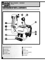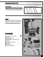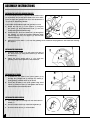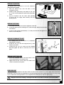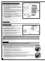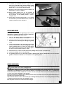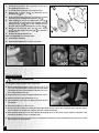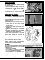
1
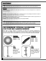
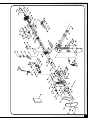
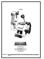
Double sealed ball bearing construction.
Adjustable aluminium tool rest.
Flexible “gooseneck” style work light.
Quick change belt tension lever facilitates
fast belt changes.
Belt sander operates horizontally and
vertically and can be locked at any
angle in between.
Perfect for knife honing and sharpening or
general shop use.
3450 RPM grinder speed to handle just
about any metal grinding application
and 4900 FPM belt speed for sanding both
hard and soft woods.
1- 60 grit sanding belt & grinding wheel
included.
BELT SIZE
1 3⁄4” x 31
7⁄ ”
8
(44 x 810 mm)
WHEEL SIZE
6” x 3⁄4” x 1⁄2” (152 x 19 x 13 mm)
BELT SPEED
4900 FPM (1500 M/MIN)
GRINDER SPEED
3450 RPM
MOTOR
1⁄ HP, 120 V, 3.7 A
3
WEIGHT
33 LBS (15 kg)
REVISION 2 OCTOBER 17/06
GENERAL® INTERNATIONAL
8360 Champ-d’Eau, Montreal (Quebec) Canada H1P 1Y3
Telephone (514) 326-1161 • Fax (514) 326-5555
www.general.ca
THANK YOU for choosing this General® International model 15-232 Belt sander
/ grinder. This Belt sander / grinder has been carefully tested and inspected before shipment
and if properly used and maintained, will provide you with years of reliable service. To ensure
optimum performance and trouble-free operation, and to get the most from your investment,
please take the time to read this manual before assembling, installing and operating the unit.
The manual’s purpose is to familiarize you with the safe operation, basic function, and features
of this Belt sander / grinder as well as the set-up, maintenance and identification of its parts and
components. This manual is not intended as a substitute for formal woodworking instruction,
nor to offer the user instruction in the craft of woodworking. If you are not sure about the safety of performing a certain operation or procedure, do not proceed until you can confirm, from
knowledgeable and qualified sources, that it is safe to do so.
Once you’ve read through these instructions, keep this manual handy for future reference.
GENERAL ® INTERNATIONAL WARRANTY
All component parts of General® International machinery are carefully tested and inspected during all stages of
production, and each machine is thoroughly inspected upon completion of assembly. Because of our commitment to quality and customer satisfaction, General® International agrees to repair or replace, within a period of 24
months from date of purchase, any genuine part or parts which, upon examination, prove to be defective in workmanship or material. In order to obtain this warranty, all defective parts must be returned freight pre-paid to
General® International Mfg. Co., Ltd. Repairs attempted without our written authorization will void this warranty.
Disclaimer: The information and specifications in this manual pertain
to the unit as it was supplied from the factory at the time of printing. Because we are committed to making constant improvements,
General® International reserves the right to make changes to components, parts or features of this unit as deemed necessary, without prior
notice and without obligation to install any such changes on previously
delivered units. Reasonable care is taken at the factory to ensure that
the specifications and information in this manual corresponds with that
of the unit with which it was supplied. However, special orders and “after
factory” modifications may render some or all information in this
manual inapplicable to your machine. Further, as several generations of
this belt sander / grinder and several versions of this manual may be in
circulation, if you own an earlier or later version of this unit, this manual
may not depict your machine exactly. If you have any doubts or
questions contact your retailer or our support line with the model and
serial number of your unit for clarification.
Rules for Safe Operation
To help ensure safe operation, please take a moment to learn the machine’s applications and limitations, as well as potential hazards. General® International disclaims any real or implied warranty and
hold itself harmless for any injury that may result from the improper use of it’s equipment.
1. Make sure that the operator has been properly trained and has read, and understands, the
owners’ manual before operating any machinery.
2. Do not operate this belt sander / bench grinder
when tired, distracted or under the effects of drugs,
alcohol or any medication that impairs reflexes or
alertness.
3. Keep the work area well lit, clean and free of debris
or clutter.
4. Keep children and visitors at a safe distance; do
not permit them to operate the unit.
5. Childproof and tamper proof your shop and
all machinery with locks, master electrical switches
and switch keys, to prevent unauthorized or
unsupervised use.
6. Stay alert! Give your work your undivided attention.
Even a momentary distraction can lead to serious
injury.
7. Do not wear loose clothing, gloves, bracelets, necklaces or other jewelry while operating machinery.
Wear protective hair covering to contain long hair
and wear non-slip footwear.
8. Fine particulate dust is a carcinogen that can
be hazardous to health. Work in a well ventilated
area and wear eye, ear and respiratory protection
devices.
9. Keep hands and other body parts well away from
the sanding belt and grinding wheel and all other
moving parts. Do not clear grinding or sanding dust
away with hands, use a brush.
10. Make sure the sanding belt and grinding wheel are
running at full operating speed before sanding or
grinding.
11. Do not force the sanding belt or grinding wheel or
push too hard. The unit will perform better, safer and
more effectively at the speed or rate for which it
was designed.
12. Never leave the power on or the machine running
while it is unattended.
13. Use recommended speed grinding wheels, accessories, and work piece material.
14. Never stand or lean on the machine. Serious injury
could occur if the unit is tipped or if unintentional
contact is made with its’ moving parts.
15. Before starting the unit, make sure the grinding
wheel is securely installed and tight to the arbor
shaft.
16. Keep all guards and safety devices in place and in
good working order. If a guard must be removed
for maintenance or cleaning make sure it is properly re-installed before using the machine again.
17. Before performing any maintenance, repairs or adjustments including belt or wheel changes, make
sure the power is off and the unit is unplugged.
18. Before plugging in and turning on the power, make
sure that any adjustment tools, keys or wrenches
have been removed and safely stored.
19. Always, make sure that switch is in "OFF" position
before plugging in the power cord.
20. Only use accessories that are made or designed
for this machine. The use of parts or accessories that
are not recommended by General® International
will void any warranty claims and may result in
injury.
21. Make sure the machine is properly grounded. This
unit is supplied with a three-prong electric plug; it
should be plugged into a three-pole electrical
receptacle. Never remove the third prong.
22. Do not use this belt sander / bench grinder for any
purpose other than it’s intended use. If used for
other purposes, General® International disclaims
any real or implied warranty and holds itself
harmless for any injury which may result from such
use.
Additional Safety Instructions
for Bench Grinders
Because each shop situation is unique, no list of safety guidelines can ever be complete.
The most important safety feature in any shop is the knowledge and good judgement of the user.
Use common sense and always keep safety considerations, as they apply to your individual shop situation first
and foremost in mind. If you have any doubts about the safety of an operation you are about to
perform: STOP! Do not perform the operation until you have validated from qualified individuals
if the operation is safe to perform and what is the safest method to perform it.
1. LIMIT EXPOSURE TO DUST
Some dust created by power sanding, sawing,
grinding, drilling and similar operations contains
chemicals known to the state of California to cause
cancer, birth defects or other reproductive harm.
Some examples include:
• Lead from lead-based paint.
• Crystalline silica from bricks, cement and
other masonry products.
• Arsenic and chromium from chemically
treated lumber.
Your risk from these exposures varies depending on
how often you do this types of work. To reduce your
exposure to these chemicals, work in a well ventilated area and work with approved safety equipment
such as dust masks that are specially designed to
filter out microscopic particles.
2. ALWAYS USE EYESHIELDS, WHEEL GUARDS AND
SPARK GUARDS
The supplied eye shields, wheel guards and spark
guards should be maintained, properly installed on
the unit and used at all times.
3. REPLACE DAMAGED PARTS OR COMPONENTS
IMMEDIATELY
Damaged parts or components may lead to a hazardous situation that could cause serious injury.
Replace any damaged parts or components before
operating the unit.
4. INSPECT GRINDING WHEELS BEFORE EACH USE
Handle grinding wheels carefully. A damaged or
chipped grinding wheel can discharge debris
towards the operator at high speeds. Before
installing or replacing a grinding wheel as well as
before each use, take a moment to inspect the
grinding wheel(s) for cracks, chips or other visible
signs of damage. Do not use a damaged wheel.
Tighten the spindle nut enough to hold the grinding
wheel firmly but do not over tighten as excessive
clamping force can damage the wheel. Use only
the wheel flanges provided with the grinder and do
not remove the blotter or label on either side of the
grinding wheel. When replacing a grinding wheel
select only wheels that are rated to a higher maximum R.P.M. than the maximum of the Bench Grinder.
5. ADJUST TOOL RESTS AND SPARK GUARDS AS
NEEDED
The diameter of the grinding wheels will decrease
with use. Adjust the tools rests and sparks guards
accordingly to maintain a distance of 1/16” from the
wheel.
6. DO NOT STAND IN FRONT OF THE BENCH
GRINDER DURING START-UP
To avoid potential injury caused by debris ejected
from a damaged wheel, stand to one side of the
Bench Grinder when starting the unit. While standing
to the side, turn the unit on, wait one minute until the
unit comes up to full speed before grinding.
7. DO NOT OPERATE IN THE VICINITY OF FLAMMABLE MATERIALS
Bench grinders will produce sparks and debris during grinding. Be sure to keep flammable materials
from the immediate vicinity. Be sure to clean the
grinding dust from the back of the Bench Grinder
frequently.
8. DO NOT FORCE THE WORKPIECE AGAINST THE
GRINDING WHEEL
Excessive force especially to a cold grinding wheel
may damage the wheel and create a dangerous
situation. Apply the workpiece against the wheel
slowly and use firm, steady even pressure. Do not
grind against the sides of the grinding wheel and do
not apply coolant direct to the grinding wheel.
9. KEEP ALL WHEEL GUARDS IN PLACE
Do not use the bench grinder with the wheel guards
removed.
10. KEEP THE TOOL RESTS FIRMLY TIGHTENED
Inspect and re-tighten tools rests before each use.
11. USE THE SUPPLIED WHEEL DRESSER
Always use the supplied wheel dresser to resurface
the face of the grinding wheel.
12. WEAR APPROVED EYE PROTECTION
Any power tool can throw foreign objects into the
eyes of the user or of those nearby. Always wear
safety goggles (not glasses) that comply with ANSI
safety standard Z87.1 Everyday eyeglasses have
only impact resistant lenses, they are not safety
goggles.
NOTES: Glasses or goggles not in compliance
with ANSI Z87.1 could result in serious injury.
ELECTRICAL REQUIREMENTS
GROUNDING INSTRUCTIONS
IN THE EVENT OF A MALFUNCTION OR BREAKDOWN,
grounding provides a path of least resistance for electric current and reduces the risk of electric shock. This
tool is equipped with an electric cord that has an
equipment-grounding conductor and a grounding
plug. The plug MUST be plugged into a matching
receptacle that is properly installed and grounded in
accordance with ALL local codes and ordinances.
DO NOT MODIFY THE PLUG PROVIDED.
If it will not fit the receptacle, have the proper receptacle installed by a qualified electrician.
This tool is intended for use on a circuit that has a
receptacle like the one illustrated in Figure
.
Figure
shows a 3-prong electrical plug
and receptacle that has a grounding conductor. If a
properly grounded receptacle is not available, an
adapter (Figure
) can be used to temporarily connect this plug to a 2-contact grounded receptacle. The
temporary adapter should be used only until a properly grounded receptacle can be installed by a qualified
technician. The adapter (Figure
) has a rigid lug
extending from it that MUST be connected to a permanent earth ground, such as a properly grounded
receptacle box. The Canadian Electrical Code prohibits the use of the adapters - check your local codes.
IMPROPER CONNECTION of the equipment-grounding
conductor can result in risk of electric shock. The conductor with green insulation (with or without yellow
stripes) is the equipment-grounding conductor. If
repair or replacement of the electric cord or plug is
necessary, DO NOT connect the equipment-grounding
conductor to a live terminal.
In all cases, make certain the receptacle is properly grounded. If you are not sure, have a qualified electrician check the receptacle.
This tool is for indoor use only. Do not expose to
rain or use in damp locations.
CHECK with a qualified electrician or service person if
you do not completely understand the grounding
instructions, or if you are not sure the tool is properly
grounded.
USE ONLY 3-WIRE EXTENSION CORDS THAT HAVE
3-PRONG GROUNDING PLUGS AND 3-POLE RECEPTACLES
THAT ACCEPT THE TOOL’S PLUG. REPAIR OR REPLACE
DAMAGED OR WORN CORD IMMEDIATELY.
GUIDELINES FOR EXTENSION CORDS
USE PROPER EXTENSION CORD.
Make sure your extension cord is in good condition.
When using an extension cord, be sure to use one
heavy enough to carry the current your product will
draw. An undersized cord will cause a drop in line
voltage, resulting in loss of power and cause overheating. The table below shows the correct size to
use depending on cord length and nameplate
ampere rating. If in doubt, use the next heavier gauge.
The smaller the gauge number, the heavier the cord.
This tool must be grounded while in use to protect
the operator from electrical shock.
BE SURE YOUR EXTENSION CORD IS PROPERLY WIRED
and in good condition. Always replace a damaged
extension cord or have it repaired by a qualified person before using it. Protect your extension cords from
sharp objects, excessive heat and damp or wet areas.
Use a separate electrical circuit for your tools. This circuit must not be less than # 12 wire and should be protected with a 15 Amp time delay fuse. Before connecting the motor to the power line, make sure the switch is
in the OFF position and the electric current is rated the
same as the current stamped on the motor nameplate.
Running at a lower voltage will damage the motor.
MINIMUM GAUGE FOR EXTENSION CORDS (AWG)
AMPERE
(When using 120 volts only)
RATING
TOTAL LENGTH OF CORD IN FEET
More than
not more than
25’
50’
100’
150’
0
6
10
12
6
10
12
16
18
18
16
14
16
16
16
12
16
14
14
14
12
12
not recommended
5
BELT SANDER / GRINDER
15-232
IDENTIFICATION OF PARTS & COMPONENTS
BELT TENSION LEVER
TOOL REST FOR GRINDER
WORK LIGHT
SWITCH
WHEEL DRESSER
QUENCH TRAY
EYE SHIELD
TOOL REST FOR SANDER
GRINDING WHEEL
SANDING BELT
BELT GUARD
6
UNPACKING AND SET-UP
SET UP SAFETY
ADDITIONAL REQUIREMENTS FOR SET UP
For your own safety, do not connect the machine
to a power source until assembly and adjustment
steps are completed, and you have read and
understood the safety and operating instructions.
• 10 mm & 13 mm open-end wrench
• Large flat head & medium phillips head screw drivers
UNPACKING
Carefully unpack and remove the unit and its components from the box and check for missing or
damaged items as per the list of contents below.
Note: Report any missing or damaged items to your
General International distributor immediately.
LIST OF CONTENTS
QTY
MACHINE (PARTIALLY ASSEMBLED) . . . . . . . . . . . .1
SPARK GUARD . . . . . . . . . . . . . . . . . . . . . . . . . . . .1
WHEEL DRESSER HOLDER . . . . . . . . . . . . . . . . . . . .1
WHEEL DRESSER . . . . . . . . . . . . . . . . . . . . . . . . . . .1
EYE SHIELD/SPARK GUARD HARDWARE BAG . . . .1
TOOL REST . . . . . . . . . . . . . . . . . . . . . . . . . . . . . . . .1
QUENCH TRAY . . . . . . . . . . . . . . . . . . . . . . . . . . . .1
BELT SANDER HARDWARE BAG . . . . . . . . . . . . . . .1
BELT GUARD . . . . . . . . . . . . . . . . . . . . . . . . . . . . . .1
EYE SHIELD . . . . . . . . . . . . . . . . . . . . . . . . . . . . . . .1
TOOL REST SUPPORT . . . . . . . . . . . . . . . . . . . . . . . .1
FASTENING HARDWARE BAG . . . . . . . . . . . . . . . . .1
7
ASSEMBLY INSTRUCTIONS
INSTALLING THE RIGHT SIDE (GRINDER) TOOL REST
The Bench Sander/Grinder is supplied with two different tool
rest assemblies. The left side (belt sander) tool rest is entirely flat. The right side (grinder) tool rest is also flat, but has a
“V” groove for sharpening drill bits.
6
5
To assemble and install the right side (grinder) tool rest:
1.
2.
3.
Attach the tool rest (1) to the support (7) using the
flat washer (2) and adjustment knob (3) from the
shield/spark guard hardware bag.
Thread the two short hex head bolts (4) through the
two washers (5) (from the fastening hardware bag)
and through the tool rest support (7) and into the
wheel housing (6).
4
Adjust the tool rest until it is 1/16” from the grinding wheel, and then firmly tighten the hex head bolts holding
the support.
INSTALLING THE SPARK GUARD
1.
Install the spark guard (1) to the inside (left side) of
the wheel cover (2) using a flat washer (3) and hex
head bolt (4).
2.
Adjust the spark guard until it is 1/16” from the
grinding wheel. Firmly tighten the hex head bolt.
INSTALLING THE EYE SHIELD
1.
Assemble the eye shield to the spark guard (1) by
inserting the carriage bolt (2) through eye shield (3),
spark guard (1) and the sleeve (4) as shown.
2.
Secure the assembly to the spark guard using a flat
washer (5) and lock knob (6) and tighten until the eye
shield remains in the desired position.
INSTALLING THE WHEEL DRESSER
8
7
1.
Peel off the adhesive backing from the wheel dresser
holder (1).
2.
Stick the holder on the top of the bench grinder (2).
3.
Insert the wheel dresser (3) on the holder.
INSTALLING THE QUENCH TRAY
The quench tray is provided to cool the workpiece
during and after grinding.
1.
Slide the quench
machine as shown.
tray
onto
the
base
of
the
2.
Partially fill the quench tray with water. Do not over
fill. Do not use any liquid in the quench tray other than
water.
3.
Dip the workpiece into the water after grinding
to cool it. Do not apply water directly onto the
grinding wheel.
INSTALLING THE BELT GUARD
1.
Loosen the two hex bolts on the lower right face of the belt.
2.
Fit the belt guard in place making sure to slide the fingers between the flat and
lock washers.
3.
Position the belt guard approximately 1/16” away from the belt and tighten the
bolts to secure it in place.
INSTALLING THE SANDING BELT TOOL REST
1.
The sanding belt tool rest comes in it’s hardware
bag partially assembled.
2.
Fit the tool rest (3) to the unit using the bolt (1) and
washer (2) as shown.
3.
Position the tool rest 1/16” away from the sanding
belt and tighten the bolt to secure the tool rest in
place.
INSTALLING THE BELT TENSION LEVER
1.
Screw the threaded end of the belt tension lever
into the threaded hole in the spring socket.
2.
Tighten down the nut on the end of the shaft to the
socket to secure the lever in place.
2
1
3
1
2
FLEXIBLE WORK LIGHT
The flexible work light operates on the same switch as used to turn the machine on or off. The light can be moved and
positioned to suit your needs for the application or operation being performed. For bulb replacement use a 110 V 10 watt
(or less) medium base track light bulb. Do not use a light bulb that extends past the end of the light housing.
Unplug the machine before installing or removing the bulb. Make sure the bulb has sufficiently cooled before handling.
9
SECURING THE BELT SANDER /GRINDER TO A WORK SURFACE
Note: To avoid tipping over or sliding during operations, the
machine should be secured to the work surface.
1.
The base of the unit has 2 mounting holes allowing the
user to permanently mount the unit to a workbench or
an optional stand.
2.
Place the unit on the work surface, mark the holes on
the work surface and drill 3/8” holes. Use appropriate
length bolts, washers and nuts (hardware not included) to secure the unit to the bench.
3.
If the workbench moves or shakes during operation,
the workbench must be fastened to the floor.
4.
The unit is designed for use on horizontal surfaces
only. Motor damage may result when mounted on a
non-horizontal surface.
1. Belt sander /
Bench grinder
2. Hex head bolt
3. Rubber washer
4. Flat washer
5. Workbench or stand
6. Flat washer
7. Lock washer
8. Hex nut
9. Jamb nut
OPERATIONS
ADJUSTMENTS AND CONTROLS
This machine is designed for hand held grinding, sharpening, cleaning and sanding operations.
The “ on/off” switch key is designed to prevent unauthorized
use when removed from the switch.
1.
To turn the unit on, insert the yellow switch key (1)
firmly into the key slot (2) of the switch.
2.
Lift the switch up to the “on” position to start the unit.
3.
To turn the unit off, push the switch down.
4.
When the belt sander /grinder comes to a complete
stop, remove the yellow switch key by gently pulling it outward.
Remove the switch key whenever the grinder is not in use. Store it in a safe place and out of the reach of children.
GRINDER OPERATION
Always wear eye protection! Hot sparks are produced during grinding operations.
1.
The power switch must be in the “OFF” position.
2.
Make sure the spark guard and tool rest is set 1/16” from the grinding wheel. Before starting the
machine, turn the grinding wheel by hand one full turn to make certain the wheel does not
come into contact with the spark guard or tool rest.
3.
Plug in the power cord to an appropriate power source.
4.
Stand to the side of the bench grinder and turn it “ON”.
5.
Allow the grinding wheel to come up to a steady speed for at least one minute.
6.
Adjust the eye shield as needed and place the workpiece on the tool rest.
7.
Slowly move the workpiece towards the grinding wheel until it lightly touches. Move the work
piece back and forth across the front surface of the grinding wheel removing the amount of
material desired. NEVER GRIND ON THE SIDES OF THE GRINDING WHEELS.
10
8.
For drill bits, lay the drill bit flat in the “V” groove. Firmly
hold on to the drill bit shank. Slide the drill bit towards
the grinding wheel until it lightly touches. Keep the drill
bit flat in the “V” groove and rotate the drill bit.
9.
Dip the hot end of the workpiece into the water in the
quench tray to cool it as needed.
10. When finished grinding turn “off” the machine by
pushing down on the power switch. Caution: it will take
a few minutes for the grinding wheel to come a
complete stop.
11. Avoid contact with the housing until it is cool. Unplug
the unit and to prevent unauthorized use, remove the
switch key and store it in a safe place.
USING THE WHEEL DRESSER
The wheel dresser is used on the grinding wheel to remove
imperfections or built-up material as well as to square up or
re-surface the grinding edge of the wheel.
1.
Turn “on” the bench grinder. Let the grinding wheel
come up to a steady speed for one minute.
2.
Place the wheel dresser (2) flat on the tool rest (1) with
the flat face of the dressing stone facing the grinding
wheel.
3.
Firmly hold the handle of the wheel dresser and slowly
move the wheel dresser forward making light contact
with the grinding wheel (3). Move the wheel dresser
from side to side across the tool rest until the edge of
the wheel is square and the surface is clean.
4.
When finished turn “off” the machine and let the grinding wheel come to a complete stop.
5.
Inspect the grinding wheel for any damage.
6.
The grinding wheel may now be slightly smaller in diameter after dressing. Readjust the tool rests and spark
guards as needed to maintain a 1/16” clearance to the grinding wheel.
CHANGING GRINDING WHEEL
To avoid injury from accidental starting, always make sure the switch is in the off position and unplug the machine
from the power source before changing wheel.
Standard size 6” (dia.) X 3/4” (wide) x 1/2” (arbor) replacement grinding wheels can be purchased in varying grits
(depending on availability) from your local tool, abrasives or sharpening supply dealer. This is a standard size
wheel that should be readily available in most areas. The use of any other size is not recommended and can lead
to serious injury and/or damage to the machine.
Note: do not remove the cardboard discs (blotters) from the sides of a new wheel because they work with the flanges to
hold and secure the wheel on the arbor.
Inspect the new wheel for cracks or other visible signs of damage that may have been caused during transport, handling
or storage. Discard the wheel if any such damage is found.
Both end plates will need to be removed for wheel changes.
11
1.
Rotate the eye-shield to the “up” position for access to
the grinding wheel tool rest.
2.
Loosen the lock knob and remove the tool rest.
3.
Remove the 5 screws (Fig.
end-plate (Fig. , #2).
4.
At the opposite end of the unit, unscrew the lock knob
and remove the sanding belt end plate. (Fig. )
5.
While holding the nut on the sanding belt side (Fig. )
with a wrench or socket remove the grinding wheel by
turning the nut (Fig. , #3) in the counterclockwise
direction with an open-end wrench or socket. (Fig. )
6.
With the nut removed take off the outer flange
(Fig. , #4), slide off the old wheel (Fig. , #5) and put a
new one on.
7.
Re-install the flange and the nut.
2
Fig.
, #1) and take off the
3
5
1
4
Note: over tightening can crack the wheel.
8.
Re-install the end-plate.
9.
Re-install and adjust the tool rest & eye-shield.
Fig.
TIGHTEN
LOOSEN
Fig.
Fig.
SANDING BELT OPERATION
ALWAYS WEAR EYE PROTECTION!
1. The power switch must be in the “off” position.
2. Before starting the machine, make sure tool rest is set
1/16” from the sanding belt - turn the belt wheel by hand
one full turn to make certain that the belt does not come
into contact with the tool rest.
3. Plug in the power cord to an appropriate power source.
4. Stand to the side of the unit and turn it “on”.
5. Allow the belt to come up to a steady speed for at least
one minute.
6. Place the workpiece on the tool rest.
7. Slowly move the workpiece towards the belt until it lightly touches. Move the workpiece back and forth across
the front surface of the belt removing the amount of material desired.
8. When finished sanding turn “off” the machine by pushing down on the power switch. Caution: it will take a few
minutes for the belt to come a complete stop.
9. Avoid contact with the housing until it is cool. Unplug the unit and to prevent unauthorized use, remove the switch
key and store it in a safe place.
12
SANDING BELT ANGLE ADJUSTMENT
Fig.
Fig.
Depending on your needs and on the sanding application,
the sanding belt assembly can be adjusted to any angle
from vertical to horizontal.
1. Make sure the power switch is in the “off” position and
that the unit is unplugged from the power source.
2. Using an allen key loosen the cap screw enough to
allow the head to tilt. (Fig. )
3. Position and hold the head at the desired angle. ( Fig.
)
4. Re-tighten the cap screw and make sure the sanding
belt is firmly held in place before starting the machine.
SANDING BELT INSTALLATION / REPLACEMENT
Standard size 1 3/4” or 2” by 31 7/8” or 32” replacement belts
can be purchased in varying grits (depending on availability) from your local tool, abrasives or sharpening
supply dealer. These are standard sizes that should be
readily available in most areas. The use of any other size is
not recommended and can lead to serious injury and/or
damage to the machine.
For best unobstructed access remove the tool rest, belt
guard and belt cover:
1. To extend belt life and avoid premature breakage
take note of the direction arrows printed on the inside
of the sanding belt to make sure you install the belt in
the correct direction.
Belt direction arrow
2. Pull and hold down the belt tension lever and remove
the sanding belt.
3. Install a new belt by slipping it onto the lower wheel
first.
4. Pull and hold down the belt tension lever and fit the
upper portion of the belt onto the upper wheel.
5. Release the belt tension lever gently to re-tension the
belt.
Note: belt tracking adjustments may be necessary after
chan-ging or replacing a sanding belt.
Turn on the machine on for 5-10 seconds to visually confirm
the belt tracking.
If the belt is tracking straight on the middle of the rollers, you
are ready to sand - re-install the belt cover, belt guard and
the tool rest and proceed with normal operations.
If the belt is not tracking straight on the middle of the rollers
follow the instructions in the next section “belt tracking”
before proceeding to normal sanding operations.
BELT TRACKING
Though not essential, proper belt tracking (having the belt running straight and as close to the center of the rollers
as possible) can prolong belt life and avoid having the belt slip off during operation.
To adjust belt tracking:
2
3
1. Loosen the inner lock knob (2).
2. Turn the adjustment knob clockwise or counter clockwise as needed (3) to adjust the belt tracking.
3. Turn on the machine for 5-10 seconds to visually confirm
the belt tracking.
Repeat this adjustment process (as needed) until the belt is
tracking on the center of rollers.
4. Tighten the inner lock knob (2) to lock in the belt tracking.
5. Re-install the belt cover, belt guard and the tool rest and
proceed with normal operations.
13
MAINTENANCE
Turn the power switch “OFF” and unplug the power cord from its power source prior to any maintenance.
LUBRICATION
The belt sander/bench grinder has sealed lubricated bearings in the motor housing that do not require any
additional lubrication.
CAUTION: remove and replace grinding wheel or sanding belt if there is any damage at all. Failure to replace a
damaged wheel or belt can cause serious injury to the operator.
CAUTION: do not use flammable materials to clean the belt sander/bench grinder. A clean dry rag or brush is all
that is needed to remove dust and debris buildup.
CAUTION: remove and replace a damaged power cord or plug immediately.
Repairs to the unit should be performed by qualified and trained personnel only. Contact your nearest
General® International dealer for authorized service. Unauthorized repairs or replacement with non-factory parts
could cause serious injury to the operator, damage to the bench grinder and void the warranty.
RECOMMENDED OPTIONAL ACCESSORIES
FOR YOUR BELT SANDER/GRINDER
We offer a large variety of products to help you increase productivity,
accuracy and safety when using your machine. Here’s is but a small sampling of
the accessories that are available from your local General® International dealer.
14
Replacement
Grinding Wheels
#15625-20 - 36 Grit
#15232-22 - 60 Grit
#15660-22 - 100 Grit
Replacement
Sanding Belts
#15-233 - 60 Grit
#15-234 - 80 Grit
#15-236 - 100 Grit
#15-237 - 120 Grit
#15-238 - 150 Grit
Stand
#15-700
Stand
#15-710
34” (863 mm). high
stand for 6” or 8”
bench grinder.
Heavy duty cast iron
table & base, tubular
steel column.
34” (863 mm) high stand
for 6”, 8” or 10” bench
grinders. Heavy duty cast
iron table & base, tubular
steel column.Water tray
Included.
15
PARTS LIST
15-232
16
PART N0.
DESCRIPTION
SPECIFICATION
15232-01
15232-02
15232-03
15232-04
15232-05
15232-06
15232-07
15232-08
15232-09
15232-10
15232-11
15232-12
15232-13
15232-14
15232-15
15232-16
15232-17
15232-18
15232-19
15232-20
15232-21
15232-22
15232-23
15232-24
15232-25
15232-26
15232-27A
15232-28
15232-29
15232-30
15232-31
15232-32
15232-33
15232-35
15232-36
15232-37
15232-38
15232-39
15232-40
15232-41
15232-42
15232-43
15232-44
15232-45
15232-46
15232-47
15232-48
15232-49
15232-50
15232-51
15232-52
15232-53
BASE
SLEEVE
STATOR
ROTOR
MOTOR FAN
BEARING
SPRING WASHER
HEX NUT
FLAT WASHER
FLAT WASHER
OUTER MOTOR GUARD
OUTER MOTOR GUARD – (L)
PHILLIPS HEAD SCREW
SPRING WASHER
INNER WHEEL GUARD - (R)
PHILLIPS HEAD SCREW W/ WASHER
WHEEL FLANGE
BELT HOSING
HEX NUT
OUTER WHEEL GUARD - (R)
BELT COVER
GRINDING WHEEL
SANDING BELT
IDLE ROLLER
PHILLIPS HEAD SCREW
TOOL REST SUPPORT
TOOL REST
FLAT WASHER
KNOB
FLAT WASHER
HEX SCREW
DRIVE ROLLER
HEX NUT
CONDENSER
CABLE
SWITCH
CORD PLATE
STRAIN RELIEF
QUENCH TRAY
PHILLIPS HEAD SCREW
SLEEVE SCREW
CAM
SWITCH PLATE
BEARING
POWER CORD
FLAT WASHER
PLATE
HEX NUT
PAD W/ WASHER & SCREW
STRAIN RELIEF
PHILLIPS HEAD SCREW W/ WASHER
SPROCKET WASHER
15-661M1
114.4 x - 110.8 x 115L
111 x 53 x 50
53 x 50 x 16
85 x 15.8
#6202ZZ
1/4
M5
5/16” x 18 x 2T
1/4” x 16 x 2T
LF- G1500VH
SB45810
M5 x 135L 20MM
M5
1/4CS 1.2MM
1/4” x 3/8”
1/4”HP - 12.7MM x 2.5T
SB-1/4
1/2”-RIGHT
1/4C 1.2MM
SB-1/4
6” x 3/4” x 1/2” A60
45 x 810 #60
SB-1/4
3/16” x 1/4”
- RIGHT
- RIGHT
1/4” x 16 x 2T
1/4” x 1”
5/16” x 18 x 2T
5/16” x 1/2”
SB-1/4
1/2-LEFT
12UF/250V
100MML+5120H #18
J-9301A 4P
18MM 16 x 1mm
137 x 33 x 2.5T
3/16” x 3/8”
M8 x 40L
SB-1/4
100 x 60 x 2T
6200ZZ
SJT18 x 3C x 2.1M
1/4” x 16 x 2T
SB45810
1/4”
ROUND
6N-4
3/16” x 1/4”
M5
QTY
1
1
1
1
1
2
1
2
1
1
1
1
2
2
1
3
3
1
1
1
1
1
1
1
5
1
1
4
1
2
2
1
1
1
2
1
1
1
1
2
1
1
1
2
1
2
1
1
4
1
5
1
PARTS LIST
15-232
PART N0.
DESCRIPTION
SPECIFICATION
15232-54
15232-55
15232-56
15232-57
15232-58
15232-59
15232-60
15232-61
15232-62
15232-63
15232-64
15232-65
15232-66
15232-67
15232-68
15232-69
15232-70
15232-71
15232-72
15232-73
15232-74
15232-75
15232-76
15232-77
15232-78
15232-79
15232-80
15232-81
15232-82
15232-83
15232-84
15232-85
15232-86
15232-87
15232-88
15232-89
15232-90
15232-91
15232-92
15232-93
15232-94
15232-95
15232-96
15232-97
15232-98
15232-99
15232-100
15232-102
15232-103
15232-104
15232-105
15232-106
COPPER WASHER
PHILLIPS HEAD SCREW W/ WASHER
EYE SHIELD
C-RING
C-RING
SEAT – IDLE ROLLER
ADJUSTING KNOB
SCREW
SPRING
SCREW
SPRING SOCKET
HANDLE
SPARK GUARD
HEX SCREW
BELT TENSION LEVER
TERMINAL
TERMINAL
WORK LIGHT
PHILLIPS HEAD SCREW WITH WASHER
SLEEVE
NAME PLATE
WHEEL DRESSER COVER (UPPER)
DRESSING STONE
DRESSER HANDLE
PHILLIPS HEAD SCREW
HEX NUT
WHEEL DRESSER HOLDER
ADHESIVE TAPE
SET SCREW
SPRING WASHER
HEX NUT
KNOB
HEX SCREW
ALLEN KEY
SET SCREW
LABEL
PLASTIC KNOB
SET SCREW
FIXING PLATE
TOOL REST
TOOL REST
SUPPORT PLATE
NUT
SPRING PIN
KNOB
COVER BRACKET
SOCKET SCREW
CONDENSER CLAMP
BELT GUARD
HEX. NUT
HEX. SCREW
CHAIN
5MM
3/16” x 1/4”
S-16
S-10
SB-1/4
6MM
6MM
SB-1/4
1/4” x 2-1/2”L
SB-1 x 6
1/4”
1/4” x 1/2”
1/4 x 1/4
73B
U2
110V - 10w
1/4 x 5/8
13 x 6.5 x 5.3L
42 x 28 x 20MM
3/16” x 1-1/4”
3/16”
1/4” x 20L
1/4”
1/4”
1/4
M8 x 12MM
6MM
3/16” x 5/16”
1/4
1/4 x 1/4
SB-1/4
1/4A
1/4B
168 x 61MM
M5 x 16MM
M4 x 16MM
1/4” x 28MM
1/4
M5 x 10MM
LOWER
3/16”
6 x 12MM
11.25CM
QTY
1
1
1
1
1
1
1
1
1
1
1
1
1
1
1
2
2
1
1
1
1
1
1
1
1
1
1
1
2
3
3
1
1
1
2
2
2
1
1
2
1
1
2
1
1
1
2
1
1
1
2
1
17
15-232
8360, Champ-d’Eau, Montreal (Quebec)
Canada H1P 1Y3
Tel.: (514) 326-1161
Fax : (514) 326-5565 Parts & Service
Fax : (514) 326-5555 Order Desk
[email protected]
www.general.ca
IMPORTANT:
When ordering replacement parts, always give the model number, serial number of
the machine and part number. Also a brief description of each item and quantity
desired.