1
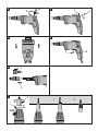
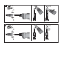
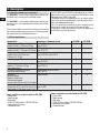
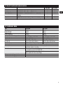
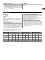
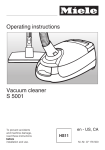
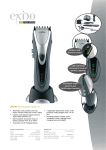
285702
*285702*
SD 4500 /
SD 2500
Operating instructions
en
Mode d’emploi
fr
Manual de instrucciones
es
Manual de instruções
pt
1
1
2
3
4
5
6
7
10
13
12
8
11
9
SMI 55 plus
3
2
2
3
1
3
1
2
4
5
2
6
1
2
7
2
1
1
Click
2
8
1
3
4
2
8
1
3
4
2
9
SD 4500 / SD 2500 drywall screwdrivers
It is essential that the operating instructions
are read before the tool is operated
for the first time.
1. General information
en
1.1 Safety notices and their meaning
Always keep these operating instructions
with the tool.
-CAUTIONDraws attention to a potentially dangerous situation that
could lead to minor personal injury or damage to the
equipment or other property.
Ensure that the operating instructions are
with the tool when it is given to other
persons.
-NOTEDraws attention to instructions and other useful information.
1.2 Pictograms
Operating controls and parts 1/4″ chuck (for bit holder, magazine bit)
Adjustable depth gauge (with bit change function)
Tool / accessory interface (click connection)
Coupling system / gearing
Motor
Belt hook
Motor cooling air intake
Lockbutton for sustained operation
Supply cord
On / off switch (with electronic speed control)
Forward / reverse switch
Type plate
Cooling air exit with controlled air flow
Warning signs
General
warning
Warning:
electricity
Obligation signs
Wear eye
protection
Symbols
Read the operating
instructions
before use.
Contents
1. General information
2. Description
3. Tools and accessories
4. Technical data
5. Safety rules
6. Before use
7. Operation
8. Care and maintenance
9. Disposal
10. Manufacturer's warranty – tools
Page
1
2
3
3
4
5
6
7
7
7
Return waste
material for
recycling
These numbers refer to the corresponding illustrations. The illustrations can be found on the fold-out cover
pages. Keep these pages open while studying the operating instructions.
In these operating instructions, the SD 4500 and / or
SD 2500 screwdriver is referred to as « the power tool ».
Location of identification data on the power tool
The type designation can be found on the rating plate
and the serial number on the side of the motor housing.
Make a note of this data in your operating instructions
and always refer to it when making an enquiry to your
Hilti representative or service department.
Type:
Serial No.:
1
2. Description
2.1 Use of the power tool as intended
The SD 4500 is a hand-held, corded power tool for professional use in the drywall installation trade.
en
The SD 2500 is a hand-held, corded power tool for professional use in the woodworking and drywall installation trades.
These power tools are used for driving and removing
the recommended types of screws in the corresponding materials of the specified thickness.
The SD 4500 and SD 2500 are designed to be used in
conjunction with a screw magazine (SMI 55 plus) and
tool extension (SME) if desired.
The power tools are intended for use on construction
sites of all kinds for applications in the drywall installation and woodworking trades.
Only the specified screwdriving bits, magazine and
accessories should be used with the power tools.
The general safety precautions listed in the operating
instructions must be observed.
2.2 Main applications
Application
Fastening drywall panels to metal
profiles (track) ≤ 0.88 mm/ 20 ga
Fastening drywall panels to metal
profiles (track) ≤ 2.25 mm/25–16 ga
Fastening metal profiles to metal
profiles (max. total thickness
2.5 mm /13–12 ga)
Fastening drywall panels to wood
Fastening drywall panels to metal
profiles (≤ 0.88 mm / 20 ga)
and wood frames
Fastening chipboard (particle
board) to wood frames
Fastening:
Wood to wood
Wood to chipboard
Chipboard to wood
Screws up to 140 mm (51⁄2 in) in length
Fastening wood to metal
Steel grade: ST 37 up to 12 mm (1⁄2 in)
Steel grade: ST 52 up to 8 mm (1⁄3 in)
Screw type / diameter in mm
Needle-point drywall screws,
type S-DS 01
Drill-point drywall screws,
type S-DD 01
Special drywall screws with drill point,
type S-DD 02 und S-DD 03
SD 2500
X
X
Needle-point drywall screws,
type S-DS 03
Needle-point drywall screws,
type S-DS 14
X
Needle-point drywall screws,
Typ S-DS 03
Wood screws
X
X
X
X
Self-drilling wing screws with drill point,
type S-WW
Items supplied as standard with the SD 4500
– Power tool
– Depth gauge
– Belt hook
– S-BH 75 M bit holder, S-B PH2 DRY bit
– Operating instructions
– Cardboard box
2
SD 4500
X
X
X
Items supplied as standard with the SD 2500
– Power tool
– Depth gauge
– Belt hook
– S-BH 75 M bit holder, S-B PH2 DRY bit
– Operating instructions
– Cardboard box
3. Insert tools and accessories
Belt hook
Depth gauge
Depth gauge
Bit and bit holder
Magazine
Extension
S-DG-D 11 x 50 for 50 mm (2") bit holder
S-DG-D 11 x 75 for 75 mm (3") bit holder
S-BH 75 M and S-BH 50 M bit holders, PH2, SQ and
TX bits
SMI 55 plus
SME extension for working on floors and ceilings
SD 4500
X
X
X
X
SD 2500
X
X
X
X
X
X
X
X
en
4. Technical data
Tool
Rated power
Rated voltage
Rated current
Rated frequency
Rated no-load running speed
Chuck
Weight of tool
Dimensions
(L × W × H)
Max. torque
Speed control
Forward / reverse
Protection class
SD 4500
SD 2500
740 W
740 W
120 V
120 V
6.5 A
6.5 A
60 Hz
60 Hz
0–2500 r.p.m.
0–4500 r.p.m.
1/4″ DIN 3126 / ISO 1173
1/4″ DIN 3126 / ISO 1173
1.5 kg (3.3 Ibs)
1.4 kg (3.1 Ibs)
303 × 75 × 160 / 168 mm
290 × 75 × 160 / 168 mm
(11.9 × 2.9 × 6.3 / 6.6 in)
(11.4 × 2.9 × 6.3 / 6.6 in)
19 Nm (168 in-lbs)
9.5 Nm (84 in-lbs)
Electronic, by control switch
Switch with interlock to prevent changing direction
while the motor is running
Electrical protection class II Z (double insulated)
in accordance with UL/CSA60745
Electrical protection class I, grounded
(50 ft cord with Twist Lock Plug)
Mechanical notch-type clutch
Vibration-absorbing grip
3
5. Safety rules
en
5.1 General safety rules
-WARNING-! Read all instructions! Failure to follow
all instructions listed below may result in electric shock,
fire and / or serious injury. The term “power tool” in all
of the warnings listed below refers to your mains operated (corded) power tool or battery operated (cordless)
power tool.
SAVE THESE INSTRUCTIONS.
5.1.1 Work area safety
a) Keep the work area clean and well lit. Cluttered and
dark areas invite accidents.
b) Do not operate power tools in explosive atmospheres, such as in the presence of flammable liquids, gases or dust. Power tools create sparks which
may ignite the dust or fumes.
c) Keep children and bystanders away while operating a power tool. Distractions can cause you to lose
control.
5.1.2 Electrical safety
a) Power tool plugs must match the outlet. Never modify the plug in any way. Do not use any adapter plugs
with earthed (grounded) power tools. Unmodified
plugs and matching outlets will reduce risk of electric shock.
b) Avoid body contact with earthed or grounded surfaces such as pipes, radiators, ranges and refrigerators. There is an increased risk of electric shock
if your body is earthed or grounded.
c) Do not expose power tools to rain or wet conditions.
Water entering a power tool will increase the risk of
electric shock.
d) Do not abuse the cord. Never use the cord for carrying, pulling or unplugging the power tool. Keep
the cord away from heat, oil, sharp edges or moving parts. Damaged or entangled cords increase the
risk of electric shock.
e) When operating a power tool outdoors, use an extension cord suitable for outdoor use. Use of a cord
suitable for outdoor use reduces the risk of electric
shock.
5.1.3 Personal safety
a) Stay alert, watch what you are doing and use common sense when operating a power tool. Do not use
a power tool while you are tired or under the influence of drugs, alcohol or medication. A moment of
inattention while operating power tools may result in
serious personal injury.
b) Use safety equipment. Always wear eye protection.
Safety equipment such as dust mask, non-skid safety
shoes, hard hat, or hearing protection used for appropriate conditions will reduce personal injuries.
c) Avoid accidental starting. Ensure the switch is in the
off position before plugging in. Carrying power tools
4
with your finger on the switch or plugging in power
tools that have the switch on invites accidents.
d) Remove any adjusting key or wrench before turning
the power tool on. A wrench or a key left attached to
a rotating part of the power tool may result in personal
injury.
e) Do not overreach. Keep proper footing and balance
at all times. This enables better control of the power
tool in unexpected situations.
f) Dress properly. Do not wear loose clothing or jewellery. Keep your hair, clothing and gloves away
from moving parts. Loose clothes, jewellery or long
hair can be caught in moving parts.
g) If devices are provided for the connection of dust
extraction and collection facilities, ensure these are
connected and properly used. Use of these devices
can reduce dust related hazards.
5.1.4 Power tool use and care
a) Do not force the power tool. Use the correct power
tool for your application. The correct power tool will
do the job better and safer at the rate for which it was
designed.
b) Do not use the power tool if the switch does not turn
it on and off. Any power tool that cannot be controlled
with the switch is dangerous and must be repaired.
c) Disconnect the plug from the power source and/or
the battery pack from the power tool before making
any adjustments, changing accessories, or storing
power tools. Such preventive safety measures reduce
the risk of starting the power tool accidentally.
d) Store idle power tools out of the reach of children
and do not allow persons unfamiliar with the power
tool or these instructions to operate the power tool.
Power tools are dangerous in the hands of untrained
users.
e) Maintain power tools. Check for misalignment or
binding of moving parts, breakage of parts and any
other condition that may affect the power tool's
operation. If damaged, have the power tool repaired
before use. Many accidents are caused by poorly
maintained power tools.
f) Keep cutting tools sharp and clean. Properly maintained cutting tools with sharp cutting edges are less
likely to bind and are easier to control.
g) Use the power tool, accessories and tool bits etc.
in accordance with these instructions and in the
manner intended for the particular type of power
tool, taking into account the working conditions and
the work to be performed. Use of the power tool for
operations different from those intended could result
in a hazardous situation.
5.1.5 Service
a) Have your power tool serviced by a qualified repair
person using only identical replacement parts. This
will ensure that the safety of the power tool is maintained.
5.2 Specific safety rules
a) Hold power tools by insulated gripping surfaces when
performing an operation where the cutting tool may
contact hidden wiring or its own cord. Contact with
a “live” wire will make exposed metal parts of the tool
“live” and shock the operator.
-WARNINGTo reduce the risk of injury, user must read instruction
manual.
en
6. Before use
-NOTEThe voltage provided by the electric supply must correspond to the information given on the type plate on
the power tool.
6.1 Using extension cords
Use only extension cords of a type approved for the
application and with conductors of adequate cross
section. Failure to observe this point may cause the
tool to loose power and the extension cord may overheat. Check the extension cord for damage at regular
intervals. Replace damaged extension cords.
●
6.2 Use of a generator or transformer
This tool may be powered by a generator or transformer
which fulfils the following conditions:
● AC voltage, output power at least 2600 W.
● The operating voltage must be within +5 % and –15 %
of the rated voltage at all times.
● Frequency range 50–60 Hz; never above 65 Hz.
● Automatic voltage regulation with starting boost.
● Never operate other tools or appliances from the generator or transformer at the same time. Switching
other tools or appliances on and off may cause undervoltage and / or overvoltage peaks, resulting in damage to the power tool.
Recommended minimum conductor cross section
and max. extension cord lengths:
Mains voltage
Conductor cross
section (mm2)
100 V
110–120 V
220–240 V
Conductor cross section
1.5
2.0
2.5
3.3
–
20 m
50 m
30 m
30 m
–
–
40 m
100 m
50 m
50 m
–
15 ft extension cord
AWG
AWG
AWG
16
14
12
1.23
1.95
3.09
25 ft
50 ft
–
75 ft
100 ft
–
100 ft
150 ft
–
50 ft extension cord
AWG
AWG
AWG
16
14
12
1.23
1.95
3.09
25 ft
50 ft
–
50 ft
75 ft
–
100 ft
125 ft
–
5
7. Operation
en -CAUTIONSecure the workpiece. Use clamps or a vice to hold the
workpiece securely in position. It is then held more
safely and both hands remain free for holding and operating the tool.
7.1 Setting forward or reverse rotation The forward / reverse switch is used to set the direction
of rotation of the drive spindle. An interlock prevents
operation of the switch while the motor is running.
– Push the forward / reverse switch to the left (as seen
when the tool is in use) = forwards.
– Push the forward / reverse switch to the right (as seen
when the tool is in use) = reverse.
7.2 Switching on / off
1. Plug the supply cord into the power outlet.
2. Press the control switch slowly. This allows the user
to select any speed between 0 and maximum.
-NOTEThe drive spindle begins to rotate only when axial pressure is applied to the tool.
7.3 Lockbutton for sustained operation The lockbutton for sustained operating mode allows
continuous operation of the tool without need for applying constant pressure to the control switch.
7.3.1 Switching on in sustained operating mode
1. Press the control switch as far as it will go and hold
it in this position.
2. Press the lockbutton and then release the control
switch.
7.3.2 Switching off after sustained operation
3. Press the control switch. The lockbutton returns to is
its original position.
7.4 Interface for insert tools and accessories 1. Unplug the supply cord from the power outlet.
2. The depth gauge can be removed simply by pulling it
away from the tool (click connection). The drive spindle is then exposed. The drive spindle must be exposed
(depth gauge removed) for the following operations:
– Using the tool to remove screws (reverse rotation)
– Changing bits
– Changing the bit holder
– Attaching the SMI 55 Plus magazine
– Tightening / redriving existing screws
6
7.5 Adjusting the depth gauge -NOTEBy adjusting the depth gauge, the screw can be driven
flush with the surface or left projecting. Each click-stop
equals an adjustment of ± 0.25 mm (see illustration).
7.5.1 To drive the screw deeper
1. Turn the depth gauge to the right.
7.5.2 To drive the screw less deeply
2. Turn the depth gauge to the left.
7.6 Removing the depth gauge 1. Pull the depth gauge forward, away from the tool.
7.7 Changing insert tools The chuck for holding insert tools (bit holder, bits etc.)
is of the standard (DIN 3126 / ISO 1173) 1/4″ hex. socket
type. The screwdriving insert tools are held in place by
a spring mechanism.
1. Unplug the supply cord from the power outlet.
2. Remove the depth gauge by pulling it forward, away
from the tool.
3. The insert tool can then be pulled out and changed
(longer bit, bit holder, etc.).
4. Refit the depth gauge to the tool.
7.8 Removing a screw Remove the depth gauge by pulling it forward, away
from the tool.
Set the forward / reverse switch to the reverse rotation
position.
The screw can then be removed.
7.9 Fitting / removing the belt hook
7.9.1 Fitting the belt hook 1. Insert the belt hook mounting lug in the ventilation
slot on the tool.
2. Push the belt hook forward (toward the chuck).
3. Secure the belt hook with the retaining screw.
7.9.2 Removing the belt hook 1. Release the belt hook by removing the retaining screw.
2. Slide the belt hook back.
3. Pull the belt hook upwards out of the ventilation slot.
8. Care and maintenance
Unplug the supply cord form the power outlet.
8.1 Care of screwdriving bits and metal parts
Clean off dirt and dust deposits adhering to the surface
of the screwdriving bits, chuck or spindle and protect
these parts from corrosion by wiping them from time
to time with an oil-soaked rag.
8.2 Care of the power tool
The outer casing of the tool is made from impact-resistant plastic. Sections of the grip are made from a synthetic rubber material.
Never operate the power tool when the ventilation slots
are blocked. Clean the ventilation slots carefully using
a dry brush. Do not permit foreign objects to enter the
interior of the power tool. Clean the outside of the power
tool at regular intervals using a slightly damp cloth. Do
not use a spray, steam pressure cleaning equipment or
running water for cleaning. This may negatively affect
the electrical safety of the power tool. Always keep the
grip surfaces of the power tool free from oil and grease.
Do not use cleaning agents which contain silicone.
8.3 Maintenance
Check all external parts of the power tool for damage at
regular intervals and check that all controls operate faultlessly. Do not operate the power tool if parts are damaged or when the controls do not function faultlessly. If
necessary, your power tool should be repaired at a Hilti
repair center.
Repairs to the electrical section of the power tool may
be carried out only by trained electrical specialists.
8.4 Checks after care and maintenance
After carrying out care and maintenance, check the power
tool for correct operation (drive and remove a screw).
9. Disposal
Most of the materials from which Hilti power tools are manufactured can be recycled. The materials must be correctly separated before they can be recycled. In many countries, Hilti has already made arrangements for taking
back your old power tools for recycling. Please ask your Hilti customer service department or Hilti representative
for further information.
10. Manufacturer's warranty – tools
Hilti warrants that the tool supplied is free of defects
in material and workmanship. This warranty is valid so
long as the tool is operated and handled correctly,
cleaned and serviced properly and in accordance with
the Hilti Operating Instructions, and the technical system is maintained. This means that only original Hilti
consumables, components and spare parts may be
used in the tool.
This warranty provides the free-of-charge repair or
replacement of defective parts only over the entire lifespan of the tool. Parts requiring repair or replacement
as a result of normal wear and tear are not covered by
this warranty.
Hilti is not obligated for direct, indirect, incidental
or consequential damages, losses or expenses in
connection with, or by reason of, the use of, or inability to use the tool for any purpose. Implied warranties
of merchantability or fitness for a particular purpose
are specifically excluded.
For repair or replacement, send tool or related parts
immediately upon discovery of the defect to the address
of the local Hilti marketing organization provided.
This constitutes Hilti's entire obligation with regard to
warranty and supersedes all prior or contemporaneous comments and oral or written agreements concerning warranties.
Additional claims are excluded, unless stringent
national rules prohibit such exclusion. In particular,
7
en
UL listed to US and Canadian safety standards
Homologué UL (conforme aux normes de sécurité américaines et canadiennes)
Producto homologado según normas de seguridad americanas y canadienses
Produto homologado de accordo com as normas de segurança americanas e canadianas
C
R
US
Hilti Corporation
Hilti = registered trademark of Hilti Corp., Schaan W 3080 0905 10-Pos. 3
Right of technical and programme changes reserved S. E. & O.
1
Printed in China © 2005
285702 / B
FL-9494 Schaan
Tel.: +423 / 234 21 11
Fax: +423 / 234 29 65
www.hilti.com