1
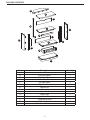
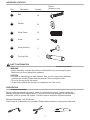
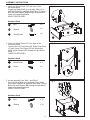
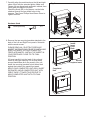
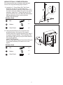
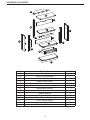
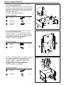
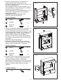
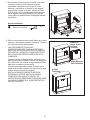
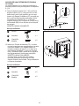
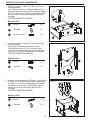
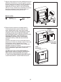
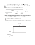
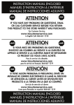
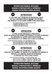
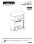
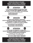
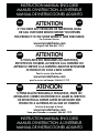
INSTRUCTION MANUAL ENCLOSED
MANUEL D’INSTRUCTION À L’INTÉRIEUR
MANUAL DE INSTRUCCIONES ADJUNTO
STOP
ATTENTION
STOP
IF YOU HAVE ANY PROBLEMS OR QUESTIONS, EMAIL
OR CALL CUSTOMER SERVICE BEFORE YOU RETURN
THIS PRODUCT TO THE STORE WHERE IT WAS PURCHASED.
For Customer Service:
www.twinstarhome.com
in English Call: 866-661-1218
ARRÊT
ATTENTION
ARRÊT
SI VOUS AVEZ DES PROBLÈMES OU QUESTIONS,
ENVOYEZ UN COURRIEL AU SERVICE À LA CLIENTÈLE OU
APPELEZ LE SERVICE À LA CLIENTÈLE AVANT DE RETOURNER
CE PRODUIT OÙ VOUS L’AVEZ ACHETÉ.
Pour le service à la clientèle:
www.twinstarhome.com
pour le service en français: 866-661-1219
PARE
ATENCIÓN
PARE
SI TIENE ALGÚN PROBLEMA O PREGUNTAS, ENVÍE UN
MENSAJE DE CORREO ELECTRÓNICO O LLAME AL SERVICIO
DE ATENCIÓN AL CLIENTE ANTES DE DEVOLVER ESTE
PRODUCTO A LA TIENDA EN LA QUE LO COMPRÓ.
Servicio de atención al cliente:
www.twinstarhome.com
Línea para llamadas en español: 866-661-1219
INSTRUCTION MANUAL ENCLOSED
MANUEL D’INSTRUCTION À L’INTÉRIEUR
MANUAL DE INSTRUCCIONES
ADJUNTO
1
ELECTRIC FIREPLACE MANTEL
26DE6439
ASSEMBLY INSTRUCTION
Españo p. 8
Français p. 15
Corner Mantel
Wall Mantel
Twin-Star International, Inc.
Delray Beach, FL 33445
Made in China
Printed in China
For Customer Service:
AT T E N T I O N
www.twinstarhome.com
Requires-Electric Fireplace
English Call: 866-661-1218
Spanish /French Call: 866-661-1219
1
Insert with Heater
PACKAGE CONTENTS
N
G
K
M
I
F
D
L
E
C
J
B
H
A
Part
A
B
C
D
E
F
G
H
I
J
K
L
M
N
Description
Hearth/Base
Left Front Panel
Right Front Panel
Center Front Panel
Left Side Panel
Right Side Panel
Mantel/Top
Drawer
Upper Shelf
Lower Shelf
Upper Back Panel
Lower Back Panel
“L” Corner Brace
Top Corner Extension
2
Quantity
1
1
1
1
1
1
1
1
1
1
1
1
1
1
HARDWARE CONTENTS
Description
Part
Picture
(Shown to size)
Quantity
AA
Bolt
36
BB
Washer
36
CC
Wood Dowel
32
DD
Screw
34
EE
Knob (with bolt)
2
ZZ
Touch-up Pen
1
SAFETY INFORMATION
WARNING
• Before assembly, carefully use scissors or utility knife to cut and unwrap all parts.
Make sure you do not discard the hardware.
CAUTION
• Use care in assembling your new fireplace. Take your time and use the hardware
provided and a quality Phillips head screwdriver. Never overtighten bolts.
• Do not sit on any part of the mantel.
• All panels are labeled left and right as viewed from the front of unit.
PREPARATION
Before beginning assembly of product, make sure all parts are present. Compare parts with
package contents list and diagram above. If any part is missing or damaged, do not attempt to
assemble, install or operate the product. Contact customer service for replacement parts.
Estimated Assembly Time: 60 Minutes
Tools Required for Assembly (not included): Phillips head screwdriver, scissors and utility knife
3
ASSEMBLY INSTRUCTIONS
1. Insert one Wood Dowel (CC) into each of the
pre-drilled holes.
Locate the Upper Shelf (I) and Lower Shelf (J) to
Left Side Panel (E) and Right Side Panel (F).Using
Bolt (AA) and Washer (BB) through the pre-drilled
holes in the mounting blocks.
HAND TIGHTEN ONLY.
Fig. 1
CC
AA
Hardware Used
AA
BB
Bolt
x8
Washer
x8
Wood Dowel
x8
F
I
BB
CC
J
E
2. Insert one Wood Dowel (CC) into each of the
pre-drilled holes.
Connect the Left Front Panel (B), Right Front Panel
(C) and Center Front Panel (D) with connection
plate, tighten Screws (DD) through the pre-drilled
holes.
HAND TIGHTEN ONLY.
Fig. 2
D
Hardware Used
CC
AA
CC
Wood Dowel
x4
DD
Screw
x2
B
C
DD
3. Locate assembly from Step 1 and Step 2.
Set out finished side up for assembly from Step 2
on the floor, attached to assembly from Step 1 Using
Bolts (AA) and Washer (BB) through the pre-drilled
holes in the mounting blocks.
HAND TIGHTEN ONLY.
Hardware Used
AA
Bolt
x 10
BB
Washer
x 10
4
Fig. 3
AA
BB
AA
BB
4. Locate Hearth/Base (A) and set out finished side up
on the floor.
Insert one Wood Dowel (CC) into each of the
pre-drilled holes.
Attach the Completed assembly from step 3 to the
Hearth/Base (A). Make sure that dowels (CC) are
seated into the pre-drilled holes in the Hearth/Base.
Using Bolts (AA) and Washers (BB) attach panels
through pre-drilled holes in the mounting blocks.
HAND TIGHTEN ONLY.
Fig. 4
AA
BB
Hardware Used
AA
Bolt
x6
BB
Washer
x6
AA
CC
Wood Dowel
x8
CC
A
5. Insert one Wood Dowel (CC) into each of the
pre-drilled holes on the top edges of the Assembly
from step 4. Then locate Mantel/Top (G) and lay
finished side up on top of completed assembly. From
the inside, attach Mantel/Top using Bolt (AA) and
Washer (BB) through the pre-drilled holes in the
mounting blocks.
HAND TIGHTEN ONLY.
Using Phillips head screwdriver tighten all Bolts
alternating top and bottom, left and right.
Hardware Used
AA
Bolt
x6
BB
Washer
x6
AA
CC
Wood Dowel
x8
Fig. 5
G
CC
BB
AA
6. Locate Upper Back Panel (K) and Lower Back Panel
(L). Attach to the Back of completed assembly from
Step 5, Using a Phillips Head screw driver, tighten
Screws (DD) to through the pre-drilled holes in
Upper Back Panel and Lower Back Panel to the
completed assembly.
Fig. 6
K
Hardware Used
DD
Screw
DD
x 32
L
5
7. Carefully align the metal tracks on the left and right
sides of box with the extended glides. Make sure
Drawer (H) are aligned and centered in cabinet, then
gently push the drawer into place.
Attach the Knob (EE) to the drawer, use the bolts
attached through the pre-drilled holes in the
drawers. Then use a Phillips Head Screw Driver to
tighten the bolts.
Fig. 7
Hardware Used
EE
Knob (with bolt)
x2
EE
H
8. Remove the two mounting brackets attached to the
back of the Left and Right Front panels. Set aside
with the wood screws.
PLEASE READ ALL “ELECTRIC FIREPLACE
INSERT” INSTRUCTIONS PRIOR TO INSTALLING
ELECTRIC INSERT IN YOUR COMPLETED
FIREPLACE MANTEL. INSTALL THE INSERT IN
YOUR FIREPLACE CLOSE TO ITS FINAL
POSITION.
Lift insert carefully into the back of the unit and
center in the insert opening. Do not drag insert
across Hearth/Base as it may scratch your unit.
Install the mounting brackets to hold insert flush
against the inside of the mantel front panel.
MOVE YOUR COMPLETED UNIT ONLY SHORT
DISTANCES. MOVE COMPLETED UNIT WITH
GREAT CARE. IT TAKES TWO PEOPLE TO
MOVE COMPLETED UNIT INTO ITS FINAL
POSITION.
6
Fig. 8
Install
Insert
From
Back
Electric
Fireplace Insert
Completed
Unit
ADDING OPTIONAL CORNER EXTENSION
We recommend having an assistant hold the back
corner of the top piece during steps 9 and 10.
Fig. 9
AA
9. Locate the “L” Corner Brace (M), Top Corner
Extension (N) and set out face down on a
scratch-free surface. Insert the Wood Dowel (CC)
into each of the pre-drilled holes on the top corner
extension. Attach the “L” Brace (M) snug to Top
Corner Extension (N), insert Bolt (AA) and Washer
(BB) into the holes in the mounting blocks.
HAND TIGHTEN ONLY.
BB
M
CC
Hardware Used
AA
Bolt
x1
BB
Washer
x1
Wood Dowel
x2
AA
CC
N
Fig. 10
10. Insert the Wood Dowel (CC) into each of the
pre-drilled holes in the bottom of the mantel.
Carefully slide the complete assembly from step 9
into place at back of Mantel. Then use Bolts (AA)
and Washers (BB) through the pre-drillled holes in
the mounting blocks.
HAND TIGHTEN ONLY.
Now you may tighten down all the bolts holding the
Corner Back assembly. Be careful not to over
tighten.
Hardware Used
AA
Bolt
x5
BB
Washer
x5
AA
CC
Wood Dowel
x2
7
CC
BB AA
CHIMENEA ELÉCTRICA
26DE6439
INSTRUCCIÓN DE MONTAJE
English. 1
Français p. 15
Repisa De Chimenea
De Esquina
Repisa De Chimenea
De Pared
Twin-Star International, Inc.
Delray Beach, FL 33445
Fabricado en China
Impreso en China
Servicio de atención al cliente:
AT E N C I Ó N
www.twinstarhome.com
Necesitará, Además, El
Hogar Eléctrico Con Calentador
Inglés llamadas:: 866-661-1218
Español /Français llamadas: 866-661-1219
8
CONTENIDO DEL PAQUETE
N
G
K
M
I
F
D
L
E
C
J
B
H
A
Pieza
A
B
C
D
E
F
G
H
I
J
K
L
M
N
Descripción
Âtre/base
Panel Frontal Izquierdo
Panel Frontal Derecho
Panel Frontal Central
Panel Lateral Izquierdo
Panel Lateral Izquierdo
Repisa/Parte Superior
Cajón
Estante Superior
Estante Inferior
Panel Trasero Superior
Panel Trasero Inferior
Soporte Angular En “L”
Pieza Angular Superior
9
Cantidad
1
1
1
1
1
1
1
1
1
1
1
1
1
1
HERRAJES INCLUIDOS
Descripción
Parte
Cantidad
AA
Perno
36
BB
Arandela
36
CC
Clavija De Madera
32
DD
Tornillo
34
EE
ZZ
Botón (Con Perno)
Stylo de retouche
Imagen
(Tamaño real)
2
1
INFORMACIÓN DE SEGURIDAD
ADVERTENCIA
• Antes del montaje, corte con unas tijeras o un bisturí y desenvuelva las piezas
cuidadosamente. Asegúrese de no desechar los herrajes.
PRECAUCIÓN
• Tenga cuidado al armar su nueva chimenea. Tómese su tiempo y use los elementos
suministrados y un destornillador Phillips de calidad. No apriete demasiado los pernos.
• No se siente en ninguna parte de la repisa de la chimenea.
• Todos los paneles están etiquetados izquierda y derecha, vistos desde el frente de la unidad.
PREPARACIÓN
Antes de empezar el montaje del producto, asegúrese de que todas las partes estén
presentes. Compare las piezas con la lista de empaque del paquete y el diagrama de arriba. Si alguna pieza falta o está dañada, no trate de armar, instalar o utilizar el producto.
Llame a servicio al cliente para piezas de repuesto.
Tiempo estimado para el montaje: 60 Minutos
Herramientas necesarias para el armado (no incluidas): Destornillador Phillips, tijeras y
un bisturí.
10
INSTRUCCIONES DE MONTAJE
1. Inserte una espiga de madera (CC) en cada uno
de los orificios pretaladrados.
Coloque el Estante Superior (I) y el Estante Inferior
(J) al Panel Lateral Izquierdo (E) y el Panel Lateral
Izquierdo (F). Utilizando Tornillos (AA) y Arandelas
(BB) a través de los agujeros pre-agujereados en
los bloques montantes.
APRIETE A MANO SOLAMENTE.
Fig. 1
CC
AA
Herrajes utilizados
BB
AA
Boulon
x8
BB
Arandela
x8
CC
Clavija De
Madera
x8
F
I
J
E
2. Inserte una espiga de madera (CC) en cada uno
de los orificios pretaladrados.
Conecte el Panel Frontal Izquierdo (B), el Panel
Frontal Derecho (C) y el Panel Frontal Central (D)
con la paleta de conexión, apriete Tornillos (DD) a
través de los agujeros pre-agujereados.
APRIETE A MANO SOLAMENTE.
Fig. 2
D
Herrajes utilizados
CC
AA
CC
Clavija De
Madera
x4
DD
Tornillo
x2
B
C
DD
3. Localice el montaje del Paso 1 y el Paso 2. Coloque
con la cara acabada hacia arriba para montar el
montaje del paso 2 en el suelo, adjuntado al
montaje del paso 1. Utilizando Tornillos (AA) y
Arandelas (BB) a través de los agujeros
pre-agujereados en los bloques montantes.
APRIETE A MANO SOLAMENTE.
Herrajes utilizados
AA
Boulon
x 10
BB
Arandela
x 10
11
Fig. 3
AA
BB
AA
BB
4. Ubique la chimenea/base (A) y colóquela con
el lado acabado hacia arriba sobre el piso.
Inserte una espiga de madera (CC) en cada uno de
los orificios pretaladrados.
Fije el ensamble frontal completo del paso 3 en la
chimenea/base (A). Asegúrese de que las espigas
de madera (CC) se asienten en los
orificios pretaladrados de la chimenea/base (A). Con
Tornillo (AA) y Arandela (BB), fije los paneles a
través de los orificios
pretaladrados en los bloques de montaje.
APRIETE A MANO SOLAMENTE.
Herrajes utilizados
AA
Boulon
x6
BB
Arandela
x6
AA
CC
Clavija De
Madera
x8
Boulon
x6
BB
Arandela
x6
AA
CC
Clavija De
Madera
x8
AA
BB
CC
A
5. Inserte una Espiga De Madera (CC) en cada uno de
los orificios previamente perforados del borde
superior del Conjunto que armó en el paso 4. Luego,
tome la Repisa/Parte Superior (G) y colóquela, con
el lado acabado hacia arrinba, sobre el conjunto
armado. Desde el interior, ajuste la Repisa
colocando un Tornillo (AA) y una Arandela (BB) en
los orificios previamente perforados de los bloques
de montaje.
APRIETE A MANO SOLAMENTE.
Utilizando un destornillador Phillips (cruciforme),
apriete todos los pernos, alternando entre la parte
superior e inferior la izquierda y la derecha.
Herrajes utilizados
AA
Fig. 4
Fig. 5
G
CC
BB
AA
Fig. 6
6. Localice el Panel Trasero Superior (K) y el Panel
Trasero Inferior (L). Adjunte a la pate trasera del
montaje completo del paso 5, utilizando un
destornillador Phillips apriete tornillos (DD) a través
de los agujeros pre-agujereados en el Panel Trasero
Superior y el Panel trasero Inferior al montaje
completo.
Herrajes utilizados
DD
Tornillo
K
DD
x 32
L
12
7. Con cuidado alinee los guías de metal a los lados
izquierdo t derecho de la caja con las guías
extendidas. Asegúrese que el Cajón (H) está
alineado y centrado en el mueble, luego empuje
suavemente el cajón en su sitio. Adjunte el Pomo
(EE) al cajón, use los tornillos adjuntados a través
de los agujeros pre-agujereados en los cajones.
Luego utilice un destornillador Phillips para apretar
los tornillos.
Fig. 7
Herrajes utilizados
EE
Botón (Con Perno)
x2
EE
H
8. Quite los dos soportes de montaje fijados en la parte
trasera de los paneles izquierdo y derecho. Coloque
a un lado los tornillos para madera.
LEA ATENTAMENTE TODAS LAS
INSTRUCCIONES DEL “HOGAR ELÉCTRICO”
ANTES DE SU INSTALACIÓN EN LA CHIMENEA
DECORATIVA. UBIQUE EL HOGAR ELÉCTRICO
EN LA POSICIÓN DEFINITIVA DENTRO DE LA
CHIMENEA.
Levante el hogar cuidadosamente, colóquelo en la
parte posterior de la unidad y céntrelo en la abertura
de la chimenea. No empuje el hogar desde su Base
dado que la unidad se puede dañar.
Coloque los soportes de montaje de modo que el
hogar se encuentre nivelado con respecto a la parte
interior del panel frontal de la repisa.
MUEVA LA UNIDAD COMPLETA SÓLO EN
DISTANCIAS CORTAS. MUEVA LA UNIDAD
COMPLETA CON MUCHO CUIDADO. SE
NECESITAN DOS PERSONAS PARA DESPLAZAR
LA UNIDAD COMPLETA AL LUGAR DEFINITIVO
QUE VA A OCUPAR.
13
Fig. 8
Instalar El
Hogar Desde
La Parte
Posterior
Hogar Eléctrico
Para Chimenea
Unidad
Terminada
ADICIÓN DE UNA EXTENSIÓN DE ESQUINA
OPCIONAL
Le recomendamos que un asistente sostenga la
esquina posterior de la pieza superior en los pasos
9 y 10.
Fig. 9
AA
BB
9. Tome el Soporte Angular En “L” (M) y la Pieza
Angular Superior (N), y colóquelos con la cara
hacia abajo, sobre una superficie que no raye.
Inserte una Espiga De Madera (CC) en cada uno
de los orificios previamente perforados. Ajuste
correctamente el Soporte En “L” a la Pieza
Angular Superior (N), e inserte los Tornillo (AA) y
las Arandela (BB) en los orificios de los bloques
de montaje.
APRIETE A MANO SOLAMENTE.
Herrajes utilizados
AA
Boulon
x1
BB
Arandela
x1
AA
CC
Clavija De
Madera
x2
Herrajes utilizados
Boulon
x5
BB
Arandela
x5
AA
CC
Clavija De
Madera
x2
CC
N
Fig. 10
10.Inserte los Toneles de Madera (CC) en cada
uno de los agujeros pre-agujereados en la parte
inferior del mueble. Con cuidado deslice el
montaje completo del paso 9 en su sitio en la
parte trasera del Mantel. Luego use Tornillos
(AA) y Arandelas (BB) a través de los agujeros
pre-agujereados en los bloques montantes.
APRIETE A MANO SOLAMENTE.
A continuación, ajuste todos los tornillos
mientras sostiene el conjunto de la Pieza
Angular Posterior del mueble. Tenga cuidado de
no ajustar demasiado.
AA
M
14
CC
BB AA
MANTEQU DE CHEMINÉE ÉLECTRIQUE
26DE6439
INSTRUCTION DE L'ASSEMBLAGE
English p. 1
Españo p. 8
Manteau Avec Coin
Manteau Sans Coin
Twin-Star International, Inc.
Delray Beach, FL 33445
Fabriqué en Chine
Imprimé en Chine
Pour le service à la clientèle :
AT T E N T I O N
www.twinstarhome.com
Nécessite AUSSI un foyer-insert
électrique avec chauffage
Anglais Appelez: 866-661-1218
Español /Français Appelez: 866-661-1219
15
CONTENU DU CARTON
N
G
K
M
I
F
D
L
E
C
J
B
H
A
Pièce
A
B
C
D
E
F
G
H
I
J
K
L
M
N
Description
Base
Panneau Avant Gauche
Panneau Avant Droit
Panneau Avant Central
Panneau Latéral Gauche
Panneau Latéral Droit
Manteau/Dessus
Tiroir
Etagère Haute
Etagère Basse
Panneau Arrière Haut
Panneau Arrière Bas
Écharpe de coin en « L »
Prolongation du coin supérieur
16
Quantité
1
1
1
1
1
1
1
1
1
1
1
1
1
1
CONTENU DU MATÉRIEL
Description
Pièce
Illustration
(en taille réelle)
Quantité
AA
Boulon
36
BB
Rondelle
36
CC
Goujon en bois
32
DD
Vis
34
EE
Bouton (avec boulon)
2
ZZ
Crayon pour retouches
1
INFORMATION DE SÉCURITÉ
AVERTISSEMENT
• Avant l’assemblage, à l’aide de ciseaux ou d’un couteau universel, coupez et déballez
soigneusement toutes les pièces. Assurez-vous de ne pas jeter de matériel.
MISE EN GARDE
• Faites preuve de prudence dans l’assemblage de votre nouvelle cheminée. Prenez
votre temps et utilisez le matériel fourni et un tournevis cruciforme de qualité. Ne serrez
pas trop les boulons.
• Ne vous asseyez pas sur des pièces du manteau.
• Tous les panneaux sont étiquetés de gauche et de droite quand on les regarde
en se tenant face à la cheminée.
PRÉPARATION
Avant de commencer l’assemblage du produit, assurez-vous que toutes les pièces sont présentes.
Comparez les pièces avec la liste du contenu de la boîte et le schéma ci-dessus. Si une pièce est
manquante ou endommagée, n’essayez pas d’assembler, d’installer ou de faire fonctionner le produit.
Communiquez avec le service à la clientèle pour obtenir des pièces de rechange.
Durée d’assemblage estimée : 60 minutes
Outils requis pour l’assemblage (non inclus) : Tournevis cruciforme, ciseaux et couteau universel
17
INSTRUCTIONS POUR L’ASSEMBLAGE
1. Insérez un goujon en bois (CC) dans chacun des
trous prépercés.
Fixer l’Etagère Haute (I) et l’Etagère Basse (J) au
Panneau Latéral Gauche (E) et au Panneau Latéral
Droit (F). Utiliser les Vis (AA) et les Rondelles (BB)
au travers des trous pré forés dans les blocs de
montage.
APRIETE A MANO SOLAMENTE.
Fig. 1
CC
AA
Matériel utilisé
AA
Boulon
BB
F
x8
I
BB
Arandela
x8
Goujon en bois
x8
J
CC
E
2. Insérez un goujon en bois (CC) dans chacun des
trous prépercés.
Raccorder le Panneau Avant Gauche (B), le
Panneau Avant Droit (C) et le Panneau Avant
Central (D) avec les plaquettes de raccordement,
serrer les Vis (DD) au travers des trous pré forés.
APRIETE A MANO SOLAMENTE.
Fig. 2
D
Matériel utilisé
CC
AA
CC
Boulon
x4
DD
Arandela
x2
B
C
DD
3. Localiser les assemblages de l’Etape 1 et de l’Etape
2. Etaler au sol coté fini vers le haut l’assemblage
de l’Etape 2, et le fixer à l’assemblage de l’Etape 1
en utilisant les Vis (AA) et les Rondelles (BB) au
travers des trous pré forés dans les blocs de
montage.
APRIETE A MANO SOLAMENTE.
Matériel utilisé
AA
Boulon
x 10
BB
Arandela
x 10
18
Fig. 3
AA
BB
AA
BB
4. Repérez la base (A) et déposez-la sur le plancher, le
côté fini vers le haut.
Insérez un goujon en bois (CC) dans chacun des
trous prépercés.
Fixez la partie avant assemblée lors de l’étape 1 à la
base (A). Assurez-vous que les goujons en bois (CC)
sont bien enfoncés dans les trous prépercés de la
base (A). Fixez les panneaux en insérant des boulon
(AA) avec des rondelle (BB) dans les trous prépercés
des blocs de montage.
APRIETE A MANO SOLAMENTE.
Matériel utilisé
AA
Boulon
x6
BB
Arandela
x6
AA
CC
Goujon en bois
x8
Boulon
x6
BB
Arandela
x6
AA
CC
Goujon en bois
x8
AA
BB
CC
A
5. Insérez un goujon en bois (CC) dans chacun des
trous pré-percés de la bordure supérieure du
panneau assemblé à l’étape 4.Trouvez ensuite le
manteau/dessus (G). Déposez le côté fini du
manteau sur le dessus du panneau entièrement
monté. De l’intérieur, fixez le manteau à l’aide d’un
boulon (AA) et d’une rondelle (BB), en les insérant
dans les trous pré-percés des blocs de montage.
APRIETE A MANO SOLAMENTE.
Avec un tournevis cruciforme, serrez tous les
goujons, en alternant entre le haut et le bas, la
gauche et la droite.
Matériel utilisé
AA
Fig. 4
6. Localiser le Panneau Arrière Haut (K) et le Panneau
Arrière Bas (L). Et les fixer au dos de l’assemblage
complété de L’Etape 5. Utiliser un tournevis
cruciforme, et serrer les Vis (DD) dans les trous
pré forés du Panneau Arrière Haut (K) et du
Panneau Arrière Bas (L) sur l’assemblage complété.
Fig. 5
G
CC
BB
AA
Fig. 6
K
Matériel utilisé
DD
Vis
DD
x 32
L
19
7. Aligner soigneusement les rails métalliques avec les
glissières extensibles sur les côtés gauche et droit
du tiroir. Assurez-vous que le Tiroir (H) est aligné et
centré par rapport au meuble, ensuite pousser
légèrement le tiroir en place. Fixer les Poignées
(EE) sur le tiroir, utiliser les vis attachées au travers
des trous pré forés du tiroir. Ensuite utiliser un
tournevis cruciforme pour serrer les vis.
Fig. 7
Matériel utilisé
EE
Bouton
(avec boulon)
x2
EE
H
8. Retirez les deux brides de montage fixées à
l’arrière des panneaux avant de gauche et de
droite. Mettez-les de côté, avec les vis à bois.
VEUILLEZ LIRE TOUTES LES INSTRUCTIONS
D’INSTALLATION DU FOYER ÉLECTRIQUE
ENCASTRABLE AVANT D’INSTALLER LE FOYER
DANS LE MANTEAU, UNE FOIS CELUI-CI
ASSEMBLÉ. INSTALLEZ LE FOYER DANS
L’ESPACE PRÉVU, PRÈS DE SA POSITION
FINALE.
Soulevez doucement le foyer encastrable pour le
déposer par l’arrière du manteau, dans le centre de
l’ouverture de celui-ci. Ne pas tirer le foyer
encastrable sur la âtre/base (A) car cela pourrait
égratigner la base du manteau.
Installez les brides de montage pour ainsi garder le
foyer encastrable à égalité avec l’intérieur du
manteau.
NE DÉPLACEZ LE FOYER ENTIÈREMENT
MONTÉ QUE SUR DE COURTES DISTANCES.
DÉPLACEZ L’UNITÉ MONTÉE AVEC SOIN.
IL FAUT DEUX PERSONNES POUR DÉPLACER
L’UNITÉ MONTÉE ET LA METTRE EN PLACE.
20
Fig. 8
Installer
le foyer
encastrable
par l’arrière
Foyer encastrable
électrique
Unité
assemblée
AJOUT DE LA RALLONGE SUPÉRIEURE EN COIN
Nous vous recommandons de faire appel à une
deuxième personne afin qu’elle tienne le coin arrière
de la rallonge supérieure en coin durant les étapes
9 et 10.
Fig. 9
AA
BB
9. Trouver écharpe de coin en « L » (M), et la
prolongation du coin supérieur (N) et les placer
face contre terre sur une surface qui ne risque
pas de s’érafler.Insérer un goujon en bois (CC)
dans chacun des trous prépercés. Unir le support
en « L » et la prolongation du coin supérieur (N)
sans qu’il y ait de jeu, insérer les boulon (AA) et
les rondelle (BB) dans les trous des blocs de
fixation.
APRIETE A MANO SOLAMENTE.
M
CC
N
Herrajes utilizados
AA
BB
AA
CC
Boulon
x1
Arandela
x1
Goujon en bois
x2
Fig. 10
10. Insérer une Cheville en Bois (CC) dans chaque
trou pré forés au bas du foyer. Glisser
soigneusement en place au dos du Foyer
l’assemblage complété de l’étape 9. Ensuite
utiliser les Vis (AA) et les Rondelles (BB) au
travers des trous pré forés dans les blocs de
montage.
APRIETE A MANO SOLAMENTE.
Vous pouvez maintenant serrer tous les boulons
retenant le coin arrière. Attention de ne pas trop
serrer.
Herrajes utilizados
AA
BB
AA
CC
Boulon
Arandela
Goujon en bois
x5
x5
x2
21
CC
BB AA