1
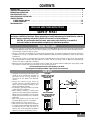
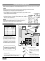
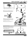
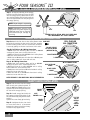
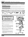
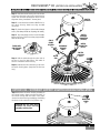
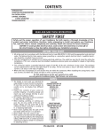
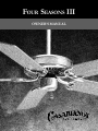
FOUR SEASONS III OWNERS MANUAL CONTENTS INTRODUCTION . . . . . . . . . . . . . . . . . . . . . . . . . . . . . . . . . . . . . . . . . . . . . . . . . . . . . . . . . . . . . . . . . . . . . . 1 MOUNTING RECOMMENDATIONS . . . . . . . . . . . . . . . . . . . . . . . . . . . . . . . . . . . . . . . . . . . . . . . . . . . . . . . . . . 2 PREPARATION INSTRUCTIONS . . . . . . . . . . . . . . . . . . . . . . . . . . . . . . . . . . . . . . . . . . . . . . . . . . . . . . . . . . . 3 FAN INSTALLATION (USA) . . . . . . . . . . . . . . . . . . . . . . . . . . . . . . . . . . . . . . . . . . . . . . . . . . . . . . . . . . . . . . . 4 FAN INSTALLATION (OUTSIDE USA) . . . . . . . . . . . . . . . . . . . . . . . . . . . . . . . . . . . . . . . . . . . . . . . . . . . . . . . . 8 CONTROL FEATURES: 3-SPEED CONTROL WIRING . . . . . . . . . . . . . . . . . . . . . . . . . . . . . . . . . . . . . . . . . . . . . . . . . . . . . . . . . . . 12 3-SPEED OPERATIONS . . . . . . . . . . . . . . . . . . . . . . . . . . . . . . . . . . . . . . . . . . . . . . . . . . . . . . . . . . . . . . . 13 TROUBLESHOOTING . . . . . . . . . . . . . . . . . . . . . . . . . . . . . . . . . . . . . . . . . . . . . . . . . . . . . . . . . . . . . . . . . . . 14 READ AND SAVE THESE INSTRUCTIONS SAFETY FIRST Safety and the proper operation of your Casablanca fan both require a thorough knowledge of the product and proper installation; therefore, before attempting to install and operate your Casablanca fan, read this owner’s manual completely and carefully. Retain this manual for future reference. CAUTION: To avoid possible electrical shock, make certain that electricity is turned off at the circuit breaker or fuse box before attempting any installation procedure. BEFORE YOU START • All wiring must be in accordance with the National Electric Code ANSI/NFPA 70-1993 and the appropriate local electrical codes. The National Electric Code requires proper grounding as a precaution against electrical shock. A qualified electrician should be consulted if you are unsure. • This fan is designed to be installed on an existing electrical outlet box. The outlet box must be UL Listed for ceiling fan installations, if it is not, a new box must be installed. Casablanca extension poles are available for sloped or high ceiling installations. • This ceiling fan requires a grounded electrical supply of 120 VAC, 60 Hz and a minimum 15 amp circuit. The maximum current requirement for the fan with light fixture is 3.8 amps. The fan uses about 1 amp or 100 watts. Maximum light current is 2.8 amps or 340 watts of lighting. • Where wire nuts are employed, be sure all bare wires are within the connectors. When installing the canopy hatch, make sure all wires are within the canopy and that no wires are being pinched. For best performance and for your warranty to be valid, use only genuine Casablanca blades, light fixtures, and accessories. SAFE USE • The blades in each pack are matched for equal weight to assure smooth fan operation. If more than one fan is being installed, be careful not to mix blades from different cartons. • Inspect the contents of your carton for possible shipping or handling damage and report any such damage directly to your authorized Casablanca dealer. • It is always a good idea to have an assistant to help with the installation. • When cleaning, painting, or working near your fan, be very careful of the fan and blades. Always turn the power OFF to the ceiling fan before servicing it, working on it, or replacing light bulbs. • Never insert anything into the path of the fan blades while the fan is in operation. • Never install a fan over a pool or spa. • Never operate a fan that has been damaged in any way. Contact Casablanca Fan Company by calling toll free 1-888-227-2178, or contact your local authorized Casablanca dealer for assistance in obtaining service. FUSE BOX (REMOVE FUSE FOR THE CIRCUIT YOU WILL BE WORKING ON) 18" 70" CIRCUIT BREAKER (TRIP BREAKER FOR THE CIRCUIT YOU WILL BE WORKING ON) P/N 8943150 REV.B P/D MAR00PDG 84" 1 MOUNTING RECOMMENDATIONS Before mounting your Casablanca fan, read the following helpful recommendations. The location of the fan, air circulation, and fan size are all important factors to consider before installation. Location Ceiling fans have practical uses in almost every room in your home. We suggest you follow these mounting recommendations as you decide where to install your Casablanca fan. • For safety reasons, the fan blades must be a minimum of 7' above the floor. • Do not locate the fan in a doorway or above a swinging door. • In any installation, the tips of the blades must be at least 18" from the wall in order to provide sufficient clearance for the blades. • In bedrooms, fans work best when mounted above the foot of the bed. • Over pool tables, be sure to provide plenty of clearance to avoid damage from pool cues. • In low ceiling locations, our optional Low Ceiling Adaptor (LCA)—available at extra cost—can be used to gain 31⁄2". • In kitchens be sure to allow for open cupboard doors to clear the fan blades. • Do not install a fan close to, or over, a pool or spa. High humidity combined Fan Size with corrosive gases will destroy the finish and warp the blades. Variable fan speed capability permits the use of a full-size 52" fan even in smaller rooms. For very large rooms, two fans may be needed. SLOPED CEILING INSTALLATIONS Suggested Extension Pole Lengths Ceiling Height Pole Length 8' Standard 8' 6" Standard 9' 6" 9' 6" 12" 10' 12" 11' 18" 12' 24" 13' 36" 14' 48" When to Use Extension Poles For best performance and best appearance, an extension pole should be used with your Casablanca fan when installing on high (cathedral) ceilings or sloped ceilings. Casablanca offers standard poles in increments of 6" up to 5'. Custom poles are available in lengths up to 10'. See your Authorized Casablanca Dealer for details. Note: Fan may wobble or vibrate if pole length is not long enough and inside blade is too close to downslope or side wall. Extending pole length will usually solve problem. Calculation of 32° Use the tear-off Ceiling Angle Template card inserted in the back of this manual, it provides you with a simple ‘go’ or ‘no-go’ for installing your fan on a sloped ceiling. 2 EXTENSION POLE MAXIMUM HANG-TRU® ANGLE 32º 32° BLADES MUST BE A MINIMUM OF 7′ ABOVE THE FLOOR 7′ MINIMUM EXAMPLE 1 This slope is less than 32˚. It is OK to install your fan. EXAMPLE 2 This slope is 32˚. This is the maximum slope that will allow the fan to hang straight down. It is OK to install your fan. EXAMPLE 3 This slope is more than 32˚. Your fan will not hang straight down, an adaptor is necessary. Contact your local Authorized Casablanca Dealer in regards to purchasing a “Slope Ceiling Adaptor.” FOUR SEASONS™ III PREPARATION INSTRUCTIONS Unpacking: Before assembling and installing your ceiling fan, remove all parts from the shipping cartons and check them against the parts listed here. Before discarding packaging material, be certain that all parts have been removed. GETTING STARTED Carton Contents The fan carton contains the fan body, warranty card, owner's Be sure to use only genuine Casablanca blades. The blade manual, and all the parts necessary to assemble and install shrink wrap holds 5 blades of matched weight. If more than your Casablanca ceiling fan. These parts are shown at the one fan is being installed, be sure not to mix blade sets. start of each installation section. Before you start, go through this Owner’s Manual and confirm that you have all the parts CAUTION: When removing the shrink wrap, shown in each section. be careful not to scratch the blades. PERMA•LOCK™ HARDWARE ALLEN SET SCREW 1 ⁄4-20 x 1⁄4" (PRE-INSTALLED) DOWNROD & BALL ASSEMBLY 3mm ALLEN WRENCH FAN PREPARATION IMPORTANT SAFETY INFORMATION! BEFORE STARTING THE INSTALLATION OF YOUR CEILING FAN, INSTALL THE THREADED DOWNROD INTO THE MOTOR COUPLING AND LOCK THE ASSEMBLY MOTOR WIRES Prepare for fan installation as follows: Step A. Route the wires from the motor through the Perma•Lock™ downrod and ball assembly. GROUND WIRE Tip: The downrod has a tapered thread that is designed to lock completely when correctly installed. DOWNROD & BALL ASSEMBLY Step B. Using the provided allen wrench, loosen the set screw several turns to allow installation of the downrod. Thread the downrod into the motor coupling until it stops turning, this will take at least four and a half full turns. Step C. Securely tighten the set screw with the provided allen wrench to ensure safe operation of your fan. TAPERED THREAD ALLEN SET SCREW CAUTION: Failure to fully lock in the downrod before securely tightening the allen set screw may cause the fan to separate from the downrod during normal operation! MOTOR COUPLING GETTING STARTED Installing a New Ceiling Fixture Outlet Box If you do not have an existing fixture located where you wish to place your Casablanca fan, an approved ceiling fixture outlet box must be installed and wired. WARNING: To reduce the risk of fire, electrical shock, or personal injury, mount to outlet box marked acceptable for ceiling fan support using the mounting hardware provided with the outlet box. Using Existing Ceiling Fixture Outlet Box After turning the power OFF at its source (either circuit breaker or fuse box), lower the old fixture and disconnect the wiring. Check the ceiling fixture outlet box to be sure that it is marked ‘Approved for ceiling fan mounting’. If it is not, a new box must be installed. NOTE: The fan weight is 17 pounds. 3 FOUR SEASONS™ III CROSSBAR MOUNTING BRACKET INSTALLATION FOR FAN INSTALLATION OUTSIDE THE USA GO TO PAGE 8 EXCLUDING MODELS ENDING IN ‘E’ CEILING FAN APPROVED WIRING BOX Proceed with installation as follows: Step 1. Route the wires from the ceiling outlet box through CEILING the crossbar mounting bracket center hole. Attach the bracket, WIRING with ground wire and ridges down, to the ceiling fixture outlet box with the mounting hardware included with the outlet CROSSBAR box. MOUNTING Tighten the screws firmly by hand only, being careful not to BRACKET bend the bracket by over tightening. RIDGE SIDE DOWN FLAT WASHER CAUTION: To reduce the risk of personal injury, use only the mounting hardware provided with the approved outlet box to install the crossbar mounting bracket. GREEN GROUND WIRE APPROVED OUTLET BOX HARDWARE CANOPY HARDWARE CANOPY SCREW (4) CANOPY LOCK WASHER (4) CANOPY HATCH CANOPY CANOPY INSTALLATION CROSSBAR MOUNTING BRACKET Step 2. Attach the canopy to the crossbar mounting bracket with three of the 8-32 x 21/4" long canopy screws and canopy lock washers. Tighten the screw firmly by hand only. NOTE: On sloped ceilings, align the canopy opening towards the top or room peak. CANOPY CANOPY LOCK WASHER CANOPY SCREW 4 FOUR SEASONS™ III SWITCH HOUSING INSTALLATION SWITCH HOUSING TIP: The packing styrofoam makes a handy work bench. Remove the bottom foam from the box. Step 3. Outside USA—Excluding Models Ending in ‘E’ Note: If you have a fan with a secondary support steel cable running through your fan motor, go to Page 8. MOTOR CONNECTOR (PLUG) STEEL CABLE (OUTSIDE USA INSTALLATION) Step 4. Hold the switch housing close to the fan and connect the motor plug to the switch housing socket. The connectors are keyed to ensure correct alignment during installation - Do not force! MOUNTING SCREW (3) SWITCH HOUSING CONNECTOR (SOCKET) SWITCH HOUSING PLATE Step 5. Remove the three mounting screws from the switch housing plate ready for the next step. SWITCH HOUSING INSTALLATION Step 6. Position the switch housing assembly on the switch housing plate and align the holes in the switch housing with the holes in the plate. Secure the switch housing assembly by reinstalling the three screws removed in the previous step. CAUTION! Do not pinch wires between the switch housing assembly and the plate. MOUNTING SCREW (3) 5 FOUR SEASONS™ III CROSSBAR MOUNTING HANGINGBRACKET THE FANINSTALLATION Step 7. To hang the fan body in the canopy, hold the fan body firmly and insert the ball into the canopy opening. Check that no wires were pinched. Rotate the fan body until the slot in the nylon ball fits into the pin opposite the canopy opening. NOTE: The fan weight is 17 pounds. NOTE: Independent control of the light fixture using a W-8 requires an additional power wire run from the wall switch to the fan. See Page 12 for wiring. BALL D1 OPTION WIRE SLOT PIN CAPPED BLUE D1-OPTION WIRE ON 3-SPEED ONLY FOR INDEPENDENT W-8 LIGHT CONTROL CANOPY ELECTRICAL CONNECTIONS PULL CHAIN OR Step 8a. Attach the fan wires to the ceiling fixture outlet WIRE NUT box wiring by twisting the bare ends of the wires together W-4 CONNECTIONS and then securing with a wire nut. Test that the connection is secure by pulling on the wire nut. Connect in this order: 2 BLACK & BLUE D1-OPTION WIRES Step 8b. Pull Chain or W-4 Wiring Connections (WITHOUT W-8) • GREEN leads from mounting plate and fan to GROUND conductor of power source. Secure with wire nut. • WHITE wire from fan to white NEUTRAL wire in ceiling fixture 2 WHITE WIRES outlet box. Secure with wire nut. • BLUE wire and BLACK power wire from fan to BLACK power 3 GREEN WIRES wire in ceiling outlet box. Secure with wire nut. Step 8c. W-8 Wiring Connections • GREEN leads from mounting plate and fan to GROUND conductor of power source. Secure with wire nut. • WHITE wire from fan to white NEUTRAL wire in ceiling fixture outlet box. Secure with wire nut. • BLACK power wire from fan to RED wire from W-8 in ceiling outlet box. Secure with wire nut. • BLUE wire from fan to YELLOW wire from W-8 in ceiling outlet box. Secure with wire nut. NOTE: SEE PAGE 12 FOR ADDITIONAL WIRING INFORMATION. W-8 CONNECTIONS BLUE & YELLOW WIRES BLACK & RED WIRES 2 WHITE WIRES 3 GREEN WIRES CANOPY HATCH INSTALLATION Step 9. Tuck the wires into the canopy with the wire nuts pointed upwards, so that the WHITE and BLACK wires are on opposite sides of the canopy and all wires are clear of the canopy opening. Step 10. Install canopy hatch with the last canopy screw and lock washer. To do this, tilt the fan body away from the hatch opening. Tighten the screws firmly by hand only. Step 11. Straighten the fan, then check to ensure that there is no movement between the canopy and ceiling or HangTru ball and top support shaft. 6 CANOPY HATCH LOCK WASHER CANOPY SCREW TILT THE FAN TO INSTALL LAST CANOPY SCREW FOUR SEASONS™ III BLADE & BLADE HOLDER HARDWARE BLADE HOLDER BLADE SCREW (3 PER BLADE) FLAT WASHER (3 PER BLADE) BLADE HOLDER SCREW (2 PER BLADE) BLADE & BLADE HOLDER INSTALLATION BLADE SCREW (3 PER BLADE) FLAT WASHER (3 PER BLADE) Step 12. Attach the blades to the blade holders with the three blade screws and flat washers provided for each blade. Hand tighten securely. Install the assembled blade and blade holder to the fan motor. Hand tighten securely. Repete for each assembly. Step 13. Attach the pull chain fob. BLADE HOLDER SCREW (2 PER BLADE HOLDER) PROCEED TO YOUR FAN’S CONTROL FEATURE SECTION ON THE PAGE 13. FOB 7 FOUR SEASONS™ III (OUTSIDE USA INSTALLATION) FAN INSTALLATION OUTSIDE THE USA - EXCLUDING MODELS ENDING IN ‘E’ If you do not have an existing fixture located where you wish to place your Casablanca fan, a new ceiling fixture outlet box must be installed (use an outlet box marked acceptable for fan support) and an electrical cable to run it. This box must be secured to the ceiling according to the outlet box manufacturer’s instructions. It is recommended that this be done by a qualified electrician. Vaulted or Cathedral Ceiling Installations Your Casablanca fan may be installed on a vaulted or cathedral ceiling in the same manner as described for a flat ceiling. The Hang-Tru® mounting system makes it possible to hang your fan on sloped ceilings up to a 32° angle. Using Existing Ceiling Fixture Outlet Box After turning electrical power off, lower the old fixture to expose the wiring and the ceiling fixture outlet box. Cut the fixture wires or if wire nuts have been used, unscrew them and disconnect the wires. The fixture can then be removed. After removing the old fixture, check the outlet box to sure that it is supported by a joist or beam across its upper surface. If not, a 2" x 4" stud must be installed. OUTSIDE USA - SECONDARY SUPPORT INSTALLATION PARTS OUTLET ADAPTOR PLATE 6" OUTLET BOX CABLE 3 ⁄8"- 7 LAG SCREW (5") FENDER WASHER SPRING LOCK HOOK OUTSIDE USA - MOUNTING SECONDARY SUPPORT PARTS TO OUTLET BOX JOIST OR BEAM WARNING: MOUNT ONLY TO AN OUTLET BOX MARKED ACCEPTABLE FOR FAN SUPPORT •••• ADVERTISSEMENT: ASSEMBLER UNIQUEMENT À UNE BÔITE DE SORTIE JUGÉE ACCEPTABLE POUR RETENIR UN VENTILATEUR. Before beginning Step 1, follow Steps A-C on Page 3. Step 1. Remove the knockout plug in the center of the outlet box or drill a 1⁄2" hole for the lag screw to pass through. Then drill a 1⁄4" guide hole into the joist or beam to a depth of 3 inches. 1 Step 2. Route the outlet box wires through the ⁄2" diameter outer hole of the outlet adaptor plate. Step 3. Line up the slotted holes and four canopy screw holes in the crossbar mounting bracket and outlet adaptor plate with the 8-32 mounting holes in the outlet box. Install the two 8-32 X 21⁄4" (1") screws and flat washers in fan hardware kit and tighten securely by hand only! Step 4. With fender washer and outlet box cable attached as shown, pass lag screw through center hole of outlet adaptor plate and screw into pre drilled 1⁄4" guide hole of joist. Tighten until outlet box is firmly mounted. 1 ⁄4" GUIDE HOLE CROSSBAR MOUNTING BRACKET 1 ⁄2" HOLE OUTLET ADAPTOR PLATE 8-32 X 21⁄4" (1") SCREW TIP: Threading two of the canopy screws into the crossbar mounting bracket will help everything stay aligned as you tighten the lag screw. Remove them before starting Step 12. 6" OUTLET BOX CABLE 8 OUTLET BOX LAG SCREW FENDER WASHER FOUR SEASONS™ III (OUTSIDE USA INSTALLATION) OUTSIDE USA - SECONDARY SUPPORT ♦ PREPARING THE SWITCH HOUSING Step 5. Hold the switch housing close to the fan and connect the motor plug to the switch housing socket. The connectors are keyed to ensure correct alignment during installation - Do not force! SWITCH HOUSING Step 6. Locate the blue and white LIGHT wires in the switch housing. Make sure they are NOT connected. Step 7. Check the tightness of the Cable Clamp & Screw. (The clamp should not slip along the cable.) SWITCH HOUSING CONNECTOR (SOCKET) Step 8. Tape completely over the end of the Cable Clamp and the end of the Secondary Support Cable with electrical tape. CABLE CLAMP & SCREW TAPED OVER CABLE CLAMP & SCREW Step 9. Pull the cable through the other side of the fan to snug the cable clamp. This makes it easier to install the switch housing. Step 10. Remove the three mounting screws from the switch housing plate. (Keep them for the next step). SECONDARY SUPPORT CABLE NYLON STOP MOTOR CONNECTOR (PLUG) SWITCH HOUSING PLATE MOUNTING SCREW (3) OUTSIDE USA - SECONDARY SUPPORT ♦ SWITCH HOUSING INSTALLATION Step 11. Position the switch housing assembly on the switch housing plate and align the holes in the switch housing with the holes in the plate. Secure the switch housing assembly by reinstalling the three screws removed in the previous step. MOUNTING SCREW (3) CAUTION! Do not pinch wires between the switch housing assembly and the plate. 9 FOUR SEASONS™ III (OUTSIDE USA INSTALLATION) OUTSIDE USA - SECONDARY SUPPORT ♦ CANOPY INSTALLATION Step 12. Attach the canopy to the crossbar mounting bracket behind the installed outlet adaptor plate with three of the 8-32 x 21⁄2" long canopy screws and lock washers provided with your Casablanca fan. Hand tighten until snug against the ceiling. NOTE: On sloped ceilings, align the canopy opening toward the top or peak of the room. Step 13. Attach the spring lock hook to the fan cable by depressing the spring lock and clipping onto the loop at the end. FAN CABLE SPRING LOCK SPRING LOCK HOOK FEED OUTLET BOX CABLE AND OUTLET BOX WIRES THROUGH CANOPY OPENING CANOPY LOCK WASHER CANOPY SCREW OUTSIDE USA - SECONDARY SUPPORT ♦ HANGING THE FAN Step 14. To hang the fan body in the canopy, hold the fan body firmly and insert the nylon ball into the canopy opening. Rotate fan body until slot on nylon ball fits into pin opposite canopy opening. Step 15. Attach the fan wires to the ceiling outlet box wiring by twisting the bare ends of the wiring together: • White wire from fan to white NEUTRAL wire in ceiling outlet box. • Black wire and blue wire from fan to black (or red) POWER wire in ceiling outlet box. • Green leads from crossbar mounting bracket and fan to grounding conductor of power source. Secure by threading on the wire nuts provided with the fan. NOTE: SEE PAGE 12 FOR ADDITIONAL WIRING INSTRUCTIONS. 10 OUTLET BOX CABLE CANOPY FAN CABLE PIN BALL SLOT FOUR SEASONS™ III (OUTSIDE USA INSTALLATION) OUTSIDE USA - SECONDARY SUPPORT ♦ COMPLETING INSTALLATION Step 16. Attach the fan cable to outlet box cable with the spring lock hook. Make sure the spring lock is tightly closed. Step 17. Tuck the wires into the canopy with the wire nuts pointed upward, so that the white and black wires are on opposite sides of the canopy and all wires are clear of the canopy opening. Tuck the extra cable and screw lock hook into the canopy. NOTE: International fans and light fixtures are supplied with plug and socket connectors. Substitute these connectors for the wire nuts shown throughout this manual. WIRE NUTS INSTALLED FAN AND OUTLET CABLES SECURED BY SPRING LOCK HOOK OUTSIDE USA - BLADE & BLADE HOLDER HARDWARE BLADE HOLDER BLADE SCREW (3 PER BLADE) FLAT WASHER (3 PER BLADE) BLADE HOLDER SCREW (2 PER BLADE) OUTSIDE USA - BLADE & BLADE HOLDER INSTALLATION Step 18. Attach the blades to the blade holders with the three blade screws and flat washers provided for each blade. Hand tighten securely. Step 19. Install the assembled blade and blade holder to the fan motor. Hand tighten securely. Repete for each assembly. BLADE SCREW (3 PER BLADE) Step 20. Attach the pull chain fob. FLAT WASHER (3 PER BLADE) PROCEED TO PAGE 13. FOB BLADE HOLDER SCREW (2 PER BLADE HOLDER) 11 3-SPEED 3-SPEED ♦ W-4 WALL CONTROL OF THE FAN • The W-4 allows the choice of four (4) different speed settings. • No light fixture is used. • Set the FAN pull chain switch to the HIGH speed setting. • No changes in household or fan wiring are required. • The fan may be turned ON and OFF by the W-4 wall control. CAUTION! Failure to set the pull-chain speed to HIGH can result in faulty operation of the fan and damage to the W-4 wall control. To confirm fan is set to HIGH: Turn W-4 fan speed switch to 'HI' - set fastest fan speed with pull chain. R 3-SPEED ♦ W-8 WALL CONTROL OF THE FAN & LIGHT(S) • The fan may be turned ON and OFF by the W-8 wall control. • The lights may be turned ON and OFF by the W-8 and the intensity adjusted from low to high. • The fan must be supplied with two independent 120V AC supply wires. • Set the FAN pull chain switch to the HIGH speed setting. • Turn the lights ON at the fan. • The W-8 allows the choice of four (4) different speed settings. CAUTION! Failure to set the pullchain speed to HIGH can result in faulty operation of the fan and damage to the W-8 wall control. To confirm fan is set to HIGH: Turn W-8 fan speed switch to 'HI' - set fastest fan speed with pull chain. 12 3-SPEED 3-SPEED ♦ OPERATION Pull-chain switches on the fan control the fan and lights. Using the fan control pull-chain switch: Fan off at start. • First pull: fan ON, low speed • Second pull: medium speed • Third pull: high speed • Fourth pull: fan OFF Using the optional light pull-chain switch: Light off at start. • First pull: light ON • Second pull: light OFF Direction of blade rotation is controlled by the reverse slide switch on the side of the switch housing. No changes in household wiring are required. OPTIONAL LIGHT PULL CHAIN SWITCH FAN & SPEED CONTROL PULL CHAIN SWITCH REVERSE SWITCH 3-SPEED ♦ OPTIONAL WALL CONTROL ♦ W-4 The W-4 wall control provides four-speed control of fan from a convenient wall location. The W-4 is designed to replace a standard wall switch and will fit wall boxes with a depth of 2" or greater. Not for use with single pull-chain fan/light option wiring. To install a W-4 wall control in place of an existing wall switch, follow the instructions on the W-4 package. Note: No rewiring is required if the fan is replacing an existing light fixture. Operation of the fan from the wall switch is simple: 1. Turn knob to obtain desired speed setting. R CAUTION! Failure to set the pull-chain speed to HIGH can result in faulty operation of the fan and damage to the W-4 wall control. To confirm fan is set to HIGH: Turn W-4 fan speed switch to 'HI' - set fastest fan speed with pull chain. 3-SPEED ♦ OPTIONAL WALL CONTROL ♦ W-8 The W-8 wall control provides separate control of fan and light with two separate knobs from a convenient wall location. The W-8 is designed to replace a standard wall switch and wall boxes with a depth of 2" or greater. Requires two hot leads from wall box to ceiling wiring box. To install a W-8 wall control in place of an existing wall switch, follow the instructions on the W-8 package. Operation of the fan from the wall switch is simple: 1. Turn the upper knob to the desired fan speed. 2. Turn the lower knob to the desired light setting. LO CAUTION! Failure to set the pull-chain speed to HIGH can result in faulty operation of the fan and damage to the W-8 wall control. To confirm fan is set to HIGH: Turn W-8 fan speed switch to 'HI' - set fastest fan speed with pull chain. SAVING MONEY WITH YOUR CEILING FAN I N S U M M E R , the movement of air creates a cooling “wind chill” effect. A room can actually feel several degrees cooler, without setting the thermostat lower. I N W I N T E R , hot air rises to the ceiling while cool air settles to the floor. Trapped against the ceiling, the warm air is wasted. If you turn up the thermostat, energy costs will rise. R U N N I N G I N R E V E R S E , your Casablanca fan can recirculate warm air near the ceiling down into the living area, providing even heating and comfort (with a pleasant effect on heating bills). 13 3-SPEED TROUBLESHOOTING BEFORE REQUESTING SERVICE: Please follow this troubleshooting guide before contacting your dealer for assistance. Caring for Finishes: For cleaning, a soft brush or lint-free cloth should be used to prevent scratching the finish. A vacuum cleaner brush nozzle can remove heavier dust. Surface smudges or an accumulation of dirt and dust can easily be removed by using a mild detergent and slightly dampened soft cloth. An antistatic agent may be used, but never use abrasive cleaning agents. These will damage the finish. Painted and high-gloss blades may be cleaned in the same manner. Blades: Wood finish blades should be cleaned with a furniture polishing cloth. Occasionally, a light coat of furniture polish may be applied for added protection and beauty. PROBLEM Never Lubricate this Fan! The precision motor at the heart of your Casablanca fan features sealed bearings that are lubricated for life. Do not attempt to oil the motor. Changing Light Bulbs Be sure to turn power to the fan OFF at the wall switch or circuit breaker before changing light bulbs. Replace bulbs with same type as removed from the fixture. Each fan is rated for a maximum TOTAL wattage of lighting. Exceeding the rated maximum allowable wattage for the fan will burn out the fan electronics module and void the warranty. 3-SPEED POSSIBLE REMEDIES.. FAN WILL NOT START Check main circuit fuses, circuit breakers, or wall switch position. Check all wire connections, making sure the power is turned off during this inspection. Check that reverse switch is not set in center of throw. FAN WOBBLES OR SHAKES EXCESSIVELY Be sure canopy pin is properly set into the slot on the ball. Check the screws holding the blade holders to the flywheel (or direct drive motor). Tighten as necessary. Check that bladeholders have not been bent during installation. FAN NOISY DURING OPERATION Check and tighten light fixture retaining screws, glass shade screws and/or the light bulb(s) as neccessary. Tighten the blade to bladeholder screws. Tighten canopy screws and mounting plate assembly. Check and tighten blade holders to flywheel (or direct drive motor). Make sure all screws in the motor housing are snug, but not overly tight. Check that the wire nuts inside the canopy and switch housing are not touching the metal parts or have fallen off the wire splices. Tighten or adjust as necessary. BREAK-IN PERIOD Let fan run at high speed for two (2) hours DOES NOT RUN ON LOW SPEED If new, “break-in” may be required - run at higher speed for several days FAN RUNS SLOWLY IN EITHER DIRECTION IF ROTATION IS STARTED BY HAND; WILL NOT REVERSE: Defective reverse switch; defective capacitor; or open motor winding: Replace reverse switch assembly; replace PCB assembly; or replace motor unit. FAN WILL NOT OPERATE AT PROPER SPEEDS OR WILL NOT OPERATE AT ANY SPEED: Defective three-speed pull-chain switch assembly; or defective capacitor: Replace three-speed pull-chain switch assembly; or replace PCB assembly. For questions or to locate the nearest Casablanca Authorized Service Center call toll free: 1-888-227-2178 or visit us on the web at: www.CasablancaFanCo.com 14 761 CORPORATE CENTER DRIVE • POMONA, CA 91768 TOLL FREE: 888-CASA-1ST (227-2178) www.CasablancaFanCo.com ©COPYRIGHT 1999 CASABLANCA FAN COMPANY • U.S. PATENT PENDING PRINTED IN ROC