1
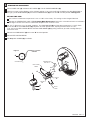
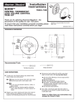
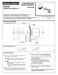
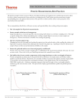
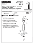
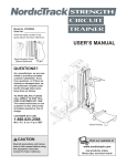
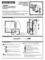
Installation
Instructions
SERIN ™
T064.740
2-HANDLE THERMOSTAT
WITH VOLUME CONTROL
TRIM KIT
Thank you for selecting American-Standard...the benchmark
of fine quality for over 100 years.
To ensure that your installation proceeds smoothly--please
read these instructions carefully before you begin.
Certified to comply with ANSI A112.18.1M
ASSE 1016
M968984 REV.1.2
ROUGHING-IN DIMENSIONS
160mm
(6-1/4)
FINISHED
WALL
200mm
(7-7/8)
100mm
(3-7/8)
186mm
(7-3/8)
R520
1/2" NPT INLETS
or
R540
3/4" NPT INLETS
150mm
(6)
25mm
NOTE: FITTING
(1)
MUST BE INSTALLED
WITH VOLUME CONTROL
ON TOP.
48mm to 68mm
(2 to 2-5/8)
Recommended Tools
Flat Blade Screwdriver
Phillips Screwdriver
CARE INSTRUCTIONS:
To keep your new faucet looking new, please follow
these simple care instructions:
DO:
Simply rinse the faucet clean with clear water.
Dry the faucet with a soft cotton cloth.
DO NOT:
Do not use any abrasive cleaners, cloths, or
paper towels.
Do not use any cleaning agents containing
acids, polish abrasives, or harsh cleaners or
soaps.
Regular and routine cleaning will reduce the need for
heavy cleaning and polishing. If heavy cleaning is
required, the following procedures are recommended:
Remove as much surface dirt and film using clear
water and soft cotton cloth (as described above).
Use any of the following to remove tough surface
film and build-up:
Mild liquid detergents
Clear ammonia free liquid glass cleaners
Non-acidic, non-abrasive gentle liquid or fully
dissolved powder cleansers mixed according to
manufacturers directions.
Non-abrasive liquid polishers
Once clean, rinse faucet again with clear water to
thoroughly remove cleaner or polish and blot dry with
a soft cotton cloth.
Failure to follow these care instructions may
damage the Faucet's finish.
1
TRIM INSTALLATION
Remove PLASTER GUARD (1) if attached.
2
Push CAPS (2 & 2a) as shown onto CONTROL
VALVES (3).
Push ESCUTCHEON HOLDER (4) with lightly greased
O-RING SEALS (5) over CAPS (2, 2a). Attach with the
two SCREWS (6) provided.
TOP
4
1
3
Align pins in back of ESCUTCHEON (7) with holes in
ESCUTCHEON HOLDER (4) and push ESCUTCHEON
(7) into place.
5
PINS
2a
7
6
1
2
INSTALL HANDLES
Align HANDLE (1) as shown and push onto KNOB MOUNT (2).
Tighten SET SCREW (3) with flat blade screwdriver.
6
8
Push COVER CAP (4) into SET SCREW (3).
5
Install HANDLE ADAPTER (5) onto VALVE STEM (6).
7
Install HANDLE SCREW (7) and tighten.
Push VOLUME CONTROL KNOB (8) onto HANDLE ADAPTER (5).
Use HEX WRENCH (9) supplied and tighten set screw to secure
VOLUME CONTROL KNOB (8).
Thread LEVER HANDLE (10) into VOLUME CONTROL KNOB (8).
10
2
9
1
3
4
3
TRANSPOSED SUPPLY PIPING
OR BACK TO BACK INSTALLATION
Should the hot and cold water supply pipes have been transposed making
adjustment impossible, proceed as follows:
Shut off water supply.
Remove handle and rim. (Reverse steps 1 and 2).
Remove check stops and re-install them transposed.
CHECK STOP
(BLUE TO RED)
Important note: RED CHECK STOP is now on the right of the mixer body and the BLUE
CHECK STOP is now on the left.
Turn the water supply back on and perform the temperature adjustment in step 4.
Assemble HANDLES and TRIM.
CHECK STOP
(RED TO BLUE)
M968984 REV.1.2
4
TEMPERATURE ADJUSTMENT
Pull out COVER CAP (1) and loosen SET SCREW (2). Pull off HANDLE ASSEMBLY (3).
Check that arrow marking B points to the 3 o'clock position. If not, push the BLACK CLAMP on the SECURING RING to
the right, pull off KNOB MOUNT (4) and reinstall KNOB MOUNT (4) with arrow "B" 3 o'clock position. See Figure 1.
SET HOT LIMIT STOP
The maximum mixed water temperature is set at 109˚F at the factory. This setting can be changed if desired.
Remove the TEMPERATURE LIMIT STOP (H shaped Black Plastic part). Reinstall it at the desired notch as indicated in
the diagram to limit the maximum mixed water temperature to 104˚F or 112˚F.
For 100 F adjustment, turn the water supply on. Turn KNOB MOUNT (4) until the spout temperature is 100˚F. Check
that arrow "A" on the KNOB MOUNT (4) still points 3 o'clock position after adjusting the thermostat to 100˚F.
If not, pull out the RED LOCKING DEVICE. Remove KNOB MOUNT (4) by pulling it towards you while standing directly in
front of the valve.
Reinstall the KNOB MOUNT (4) with arrow "A" 3 o'clock position.
Reinstall RED LOCKING DEVICE.
See Step 2 for HANDLE (3) installation.
Figure 1
ARROWS AT 3 O'CLOCK
POSITION
4
TEMPERATURE
LIMIT STOP
KNOB MOUNT
RED LOCKING
DEVICE
112
109
3
4
104
ARROW
"B"
ARROW
"A"
2
1
BLACK
CLAMP
M968984 REV.1.2