1
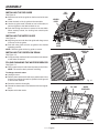
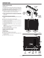
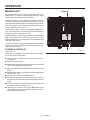
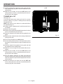
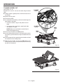
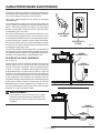
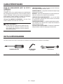
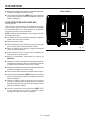
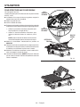
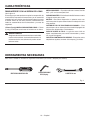
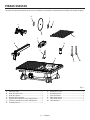
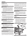
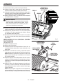
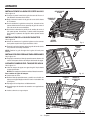
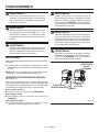
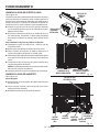
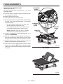
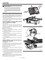
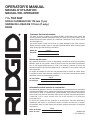
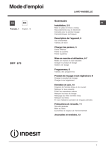
OPERATOR’S MANUAL 7 in. TILE SAW R4020 To register your RIDGID product, please visit: http://register.RIDGID.com Pour enregistrer votre produit de RIDGID, s’il vous plaît la visite: http://register.RIDGID.com Para registrar su producto de RIDGID, por favor visita: http://register.RIDGID.com Your tile saw has been engineered and manufactured to our high standards for dependability, ease of operation, and operator safety. When properly cared for, it will give you years of rugged, trouble-free performance. WARNING: To reduce the risk of injury, the user must read and understand the operator’s manual before using this product. Thank you for buying a RIDGID® product. SAVE THIS MANUAL FOR FUTURE REFERENCE TABLE OF CONTENTS Introduction....................................................................................................................................................................... 2 General Safety Rules......................................................................................................................................................3-4 Specific Safety Rules......................................................................................................................................................... 5 Symbols............................................................................................................................................................................. 6 Electrical.........................................................................................................................................................................7-8 Features........................................................................................................................................................................9-10 Tools Needed................................................................................................................................................................... 10 Loose Parts..................................................................................................................................................................... 11 Assembly....................................................................................................................................................................12-14 Operation....................................................................................................................................................................15-20 Adjustments..................................................................................................................................................................... 21 Maintenance.................................................................................................................................................................... 22 Warranty.......................................................................................................................................................................... 23 Parts Ordering and Service................................................................................................................................Back page INTRODUCTION This product has many features for making its use more pleasant and enjoyable. Safety, performance, and dependability have been given top priority in the design of this product making it easy to maintain and operate. 2 — English GENERAL SAFETY RULES WARNING: Read and understand all instructions. Failure to follow all instructions listed below, may result in electric shock, fire and/or serious personal injury. READ ALL INSTRUCTIONS KNOW YOUR POWER TOOL. Read the operator’s manual carefully. Learn the saw’s applications and limitations as well as the specific potential hazards related to this tool. GUARD AGAINST ELECTRICAL SHOCK BY PREVENTING BODY CONTACT WITH GROUNDED SURFACES. For example, pipes, radiators, ranges, refrigerator enclosures. KEEP GUARDS IN PLACE and in good working order. REMOVE ADJUSTING KEYS AND WRENCHES. Form habit of checking to see that keys and adjusting wrenches are removed from tool before turning it on. KEEP WORK AREA CLEAN. Cluttered areas and benches invite accidents. DO NOT leave tools or pieces of tile on the saw while it is in operation. DO NOT USE IN DANGEROUS ENVIRONMENTS. Do not use power tools in damp or wet locations or expose to rain. Keep the work area well lit. KEEP CHILDREN AND VISITORS AWAY. All visitors should wear safety glasses and be kept a safe distance from work area. Do not let visitors contact tool or extension cord while operating. MAKE WORKSHOP CHILDPROOF with padlocks and master switches, or by removing starter keys. DON’T FORCE TOOL. It will do the job better and safer at the feed rate for which it was designed. USE RIGHT TOOL. Don’t force the tool or attachment to do a job it was not designed for. Don’t use it for a purpose not intended. USE THE PROPER EXTENSION CORD. Make sure your extension cord is in good condition. Use only a cord heavy enough to carry the current your product will draw. An undersized cord will cause a drop in line voltage resulting in loss of power and overheating. A wire gauge size (A.W.G.) of at least 14 is recommended for an extension cord 25 feet or less in length. If in doubt, use the next heavier gauge. The smaller the gauge number, the heavier the cord. DRESS PROPERLY. Do not wear loose clothing, gloves, neckties, or jewelry. They can get caught and draw you into moving parts. Rubber gloves and nonskid footwear (rubber soled boots) are recommended when working outdoors. Also wear protective hair covering to contain long hair. ALWAYS WEAR SAFETY GLASSES WITH SIDE SHIELDS. Everyday eyeglasses have only impactresistant lenses, they are NOT safety glasses. SECURE WORK. Use clamps or a vise to hold work when practical, it is safer than using your hand and frees both hands to operate the tool. DON’T OVERREACH. Keep proper footing and balance at all times. MAINTAIN TOOLS WITH CARE. Keep tools sharp and clean for better and safer performance. Follow instructions for lubricating and changing accessories. DISCONNECT TOOLS. When not in use, before servicing, or when changing attachments, wheels, bits, cutters, etc., all tools should be disconnected. AVOID ACCIDENTAL STARTING. Be sure switch is off when plugging in any tool. USE RECOMMENDED ACCESSORIES. Consult the operator’s manual for recommended accessories. The use of improper accessories may risk injury. NEVER STAND ON TOOL. Serious injury could occur if the tool is tipped or if the cutting tool is unintentionally contacted. CHECK DAMAGED PARTS. Before further use of the tool, a guard or other part that is damaged should be carefully checked to determine that it will operate properly and perform its intended function. Check for alignment of moving parts, binding of moving parts, breakage of parts, mounting and any other conditions that may affect its operation. A guard or other part that is damaged must be properly repaired or replaced by an authorized service center to avoid risk of personal injury. USE THE RIGHT DIRECTION OF FEED. Feed work into a wheel or cutter against the direction of rotation of wheel or cutter only. NEVER LEAVE TOOL RUNNING UNATTENDED. TURN THE POWER OFF. Don’t leave tool until it comes to a complete stop. PROTECT YOUR LUNGS. Wear a face or dust mask if the cutting operation is dusty. PROTECT YOUR HEARING. Wear hearing protection during extended periods of operation. DO NOT ABUSE CORD. Never yank cord to disconnect from receptacle. Keep cord away from heat, oil, and sharp edges. ALWAYS USE AN OUTDOOR EXTENSION CORD MARKED “W-A” OR “W”. These cords are rated for outdoor use and reduce the risk of electric shock. ALWAYS KEEP THE WHEEL GUARD IN PLACE and in working order. 3 — English GENERAL SAFETY RULES KEEP HANDS AWAY FROM CUTTING AREA. Keep hands away from wheels. Do not reach underneath work or around or over the wheel while wheel is rotating. Do not attempt to remove cut material when wheel is moving. KEEP TOOL DRY, CLEAN, AND FREE FROM OIL AND GREASE. Always use a clean cloth when cleaning. Never use brake fluids, gasoline, petroleum-based products, or any solvents to clean tool. WHEEL COASTS AFTER BEING TURNED OFF. STAY ALERT AND EXERCISE CONTROL. Watch what you are doing and use common sense. Do not operate tool when you are tired. Do not rush. NEVER USE IN AN EXPLOSIVE ATMOSPHERE. Normal sparking of the motor could ignite fumes. INSPECT TOOL CORDS PERIODICALLY. If damaged, have repaired by a qualified service technician at an authorized service facility. The conductor with insulation having an outer surface that is green with or without yellow stripes is the equipment-grounding conductor. If repair or replacement of the electric cord or plug is necessary, do not connect the equipment-grounding conductor to a live terminal. Repair or replace a damaged or worn cord immediately. Stay constantly aware of cord location and keep it well away from the rotating wheel. INSPECT EXTENSION CORDS PERIODICALLY and replace if damaged. GROUND ALL TOOLS. If tool is equipped with threeprong plug, it should be plugged into a three-hole electrical receptacle. ONLY POWER THE TOOL WITH A GFCI (GROUND FAULT CIRCUIT INTERRUPTOR) PROTECTED OUTLET. CHECK WITH A QUALIFIED ELECTRICIAN or service personnel if the grounding instructions are not completely understood or if in doubt as to whether the tool is properly grounded. USE ONLY CORRECT ELECTRICAL DEVICES: 3-wire extension cords that have 3-prong grounding plugs and 3-pole receptacles that accept the tool's plug. DO NOT MODIFY the plug provided. If it will not fit the outlet, have the proper outlet installed by a qualified electrician. DO NOT USE TOOL IF SWITCH DOES NOT TURN IT ON AND OFF. Have defective switches replaced by an authorized service center. USE ONLY CORRECT WHEELS. Do not use wheels with incorrect size holes. Never use washers or arbor nuts that are defective or incorrect. The maximum wheel capacity of your saw is 7 in. (178 mm). BEFORE MAKING A CUT, BE SURE ALL ADJUSTMENTS ARE SECURE. NEVER TOUCH WHEEL or other moving parts during use. NEVER START A TOOL WHEN ANY ROTATING COMPONENT IS IN CONTACT WITH THE WORKPIECE. DO NOT OPERATE A TOOL WHILE UNDER THE INFLUENCE OF DRUGS, ALCOHOL, OR ANY MEDICATION. WHEN SERVICING use only identical replacement parts. Use of any other parts may create a hazard or cause product damage. USE ONLY RECOMMENDED ACCESSORIES listed in this manual or addendums. Use of accessories that are not listed may cause the risk of personal injury. Instructions for safe use of accessories are included with the accessory. DOUBLE CHECK ALL SETUPS. Make sure wheel is tight and not making contact with saw or workpiece before connecting to power supply. 4 — English SPECIFIC SAFETY RULES SECURE WORK firmly against the miter guide or fence. NEVER stand or have any part of your body in line with the path of the wheel. ALWAYS TURN OFF SAW before disconnecting it, to avoid accidental starting when reconnecting to power supply. NEVER attempt to free a stalled wheel without first turning the saw OFF and disconnecting the saw from the power source. IF THE POWER SUPPLY CORD IS DAMAGED, it must be replaced only by the manufacturer or by an authorized service center to avoid risk. AVOID AWKWARD OPERATIONS AND HAND POSITIONS where a sudden slip could cause your hand to move into the cutting tool. MAKE SURE THE WORK AREA HAS AMPLE LIGHTING to see the work and that no obstructions will interfere with safe operation BEFORE performing any work using the saw. THIS TOOL should have the following markings: a) Wear eye, hearing, and breathing protection. b) Use wheel guard for every operation for which it can be used. c) Disconnect saw before servicing, when changing cutting wheels, and cleaning. d) Use tool only with smooth edge cutting wheels free of openings, grooves, and teeth. e) Replace damaged cutting wheel before operating. f) Do not fill water bath above water fill line. SAVE THESE INSTRUCTIONS. Refer to them frequently and use to instruct other users. If you loan someone this tool, loan them these instructions too. WARNING: Some dust created by power sanding, sawing, grinding, drilling, and other construction activities contains chemicals known to cause cancer, birth defects or other reproductive harm. Some examples of these chemicals are: •lead from lead-based paints, •crystalline silica from bricks and cement and other masonry products, and •arsenic and chromium from chemically-treated lumber. Your risk from these exposures varies, depending on how often you do this type of work. To reduce your exposure to these chemicals: work in a well ventilated area, and work with approved safety equipment, such as those dust masks that are specially designed to filter out microscopic particles. 5 — English SYMBOLS The following signal words and meanings are intended to explain the levels of risk associated with this product. SYMBOL SIGNAL MEANING DANGER: Indicates an imminently hazardous situation, which, if not avoided, will result in death or serious injury. WARNING: Indicates a potentially hazardous situation, which, if not avoided, could result in death or serious injury. CAUTION: Indicates a potentially hazardous situation, which, if not avoided, may result in minor or moderate injury. CAUTION: (Without Safety Alert Symbol) Indicates a situation that may result in property damage. Some of the following symbols may be used on this tool. Please study them and learn their meaning. Proper interpretation of these symbols will allow you to operate the tool better and safer. SYMBOLNAME DESIGNATION/EXPLANATION Safety Alert Indicates a potential personal injury hazard. Read Operator’s Manual To reduce the risk of injury, user must read and understand operator’s manual before using this product. Eye, Ear, & Breathing Protection Always wear eye protection with side shields marked to comply with ANSI Z87.1 along with hearing and breathing protection. Wet Conditions Alert Do not expose to rain or use in damp locations. No Hands Failure to keep your hands away from the wheel will result in serious personal injury. Electrocution Failure to properly ground can result in electrocution. V Volts Voltage A Amperes Current Hz Hertz Frequency (cycles per second) min Minutes Time Alternating Current Type of current No Load Speed Rotational speed, at no load Per Minute Revolutions, strokes, surface speed, orbits etc., per minute no .../min 6 — English ELECTRICAL EXTENSION CORDS ELECTRICAL CONNECTION Use only 3-wire extension cords that have 3-prong grounding plugs and 3-pole receptacles that accept the tool’s plug. When using a power tool at a considerable distance from the power source, use an extension cord heavy enough to carry the current that the tool will draw. An undersized extension cord will cause a drop in line voltage, resulting in a loss of power and causing the motor to overheat. Use the chart provided below to determine the minimum wire size required in an extension cord. Only round jacketed cords listed by Underwriter’s Laboratories (UL) should be used. This tool is powered by a precision built electric motor. It should be connected to a power supply that is 120 V, AC only (normal household current), 60 Hz. Do not operate this tool on direct current (DC). A substantial voltage drop will cause a loss of power and the motor will overheat. If the saw does not operate when plugged into an outlet, double check the power supply. **Ampere rating (on tool data plate) 0-2.0 2.1-3.4 3.5-5.0 5.1-7.0 7.1-12.0 12.1-16.0 Cord LengthWire Size (A.W.G.) 25'16 16161614 14 50'16 16161414 12 100'16 16141210 — **Used on 12 gauge - 20 amp circuit. NOTE: AWG = American Wire Gauge Always use an extension cord that is designed for outside use. This is indicated by the letters “W-A” or “W” on the cord’s jacket. Before using an extension cord, inspect it for loose or exposed wires and cut or worn insulation. Use only extension cords that are intended for outdoor use. These extension cords are identified by a marking “Acceptable for use with outdoor appliances; store indoors while not in use”. Use only extension cords having an electrical rating not less than the rating of the product. Do not use damaged extension cords. Examine extension cord before using and replace if damaged. Do not abuse extension cords and do not yank on any cord to disconnect. Keep cord away from heat and sharp edges. Always disconnect the extension cord from the receptacle before disconnecting the product from the extension cord. SPEED AND WIRING The no-load speed of this tool is approximately 3,450 rpm. This speed is not constant and decreases under a load or with lower voltage. For voltage, the wiring in a shop is as important as the motor’s horsepower rating. A line intended only for lights cannot properly carry a power tool motor. Wire that is heavy enough for a short distance will be too light for a greater distance. A line that can support one power tool may not be able to support two or three tools. GROUNDING INSTRUCTIONS See Figure 1. This tool must be grounded. In the event of a m alfunction or breakdown, grounding provides a path of least resistance for electric current to reduce the risk of electric shock. This tool is equipped with an electric cord having an equipmentgrounding conductor and a grounding plug. The plug must be plugged into a matching outlet that is properly installed and grounded in accordance with all local codes and ordinances. Do not modify the plug provided. If it will not fit the outlet, have the proper outlet installed by a qualified electrician. WARNING: Improper installation of the grounding plug can result in a risk of electric shock. When repair or replacement of the cord is required, do not connect the grounding wire to either flat blade terminal. The wire with insulation having an outer surface that is green with or without yellow stripes is the grounding wire. WARNING: Keep the extension cord clear of the working area. Position the cord so that it will not get caught on lumber, tools or other obstructions while you are working with a power tool. Failure to do so can result in serious personal injury. WARNING: Check extension cords before each use. If damaged replace immediately. Never use tool with a damaged cord since touching the damaged area could cause electrical shock resulting in serious injury. Check with a qualified electrician or service personnel if the grounding instructions are not completely understood, or if in doubt as to whether the tool is properly grounded. Repair or replace a damaged or worn cord immediately. This product is for use on a nominal 120 volt circuit and has a grounding plug similar to the plug illustrated in figure 1. Only connect the product to an outlet having the same configuration as the plug. Do not use an adapter with this product. Ground Fault Circuit Interrupter (GFCI) protection should be provided on the circuit(s) or outlet(s) to be used for the tile saw. Outlets are available having built-in GFCI protection and may be used for this measure of safety. 7 — English ELECTRICAL If the saw is used with an extension cord, ensure the connection of the tool’s power cord and the extension cord are not on the ground. If a protected outlet is not available, do not use the saw until an outlet can be changed or auxiliary protection can be obtained. These auxiliary protection devices are available at your local retailer. POSITION OF THE TILE SAW See Figure 2. To avoid the possibility of the tool plug or outlet getting wet, position tile saw to one side of a wall-mounted outlet to prevent water from dripping onto the outlet or plug. The operator should arrange a “drip loop” in the cord connecting the saw to the outlet. The “drip loop” is that part of the cord below the level of the outlet, or the connector if an extension cord is used, to prevent water traveling along the cord and coming in contact with the outlet. If the plug or outlet does get wet, DO NOT unplug the cord. Disconnect the fuse or circuit breaker that supplies power to the tool then unplug and examine for the presence of water in the outlet. GROUNDING PIN GROUND FAULT OUTLET Fig. 1 POWER CORD WARNING: To reduce the risk of electrocution, keep all connections dry and off the ground. Do not touch the plug with wet hands. DRIP LOOP EXTENSION CORD Fig. 2 8 — English FEATURES PRODUCT SPECIFICATIONS Wheel Diameter.............................................................7 in. Wheel Arbor............................................................... 5/8 in. Rip Capacity (tile size).................................................18 in. Diagonal Capacity (tile size)........................................12 in. Maximum Depth of Cut.......................................... 1-1/4 in. Rating...........................................120 V~, 6.5 Amps, 60 Hz No Load Speed......................................3,450 r/min. (RPM) MAX WATER FILL LINE MITER GUIDE WATER RESERVOIR OVERFLOW DRAIN RIP GUIDE SCALE RIP GUIDE ON/OFF SWITCH SPLASH HOOD TILE CUTTING WHEEL BEVEL TABLE CORD STORAGE Fig. 3 9 — English FEATURES KNOW YOUR TILE SAW See Figure 3. The safe use of this product requires an understanding of the information on the tool and in this operator’s manual as well as a knowledge of the project you are attempting. Before use of this product, familiarize yourself with all operating features and safety rules. 7 in. TILE CUTTING WHEEL - A 7 in. tile cutting wheel is included with your saw. WARNING: Do not use wheels rated less than the speed of this tool. Failure to heed this warning could result in personal injury. BEVEL TABLE - Beveled 22.5° and 45° cuts can be made using the bevel table. MITER GUIDE - The easy-to-read indicator on the miter guide shows the exact angle for the desired cut. MOTOR - This machine has a strong motor with sufficient power to handle tough cutting jobs. ON/OFF SWITCH - This saw has an easy access on/off switch located below the front rail. RIP GUIDE - Rip guide is fully adjustable for making cross cuts and using the miter guide. SPLASH HOOD - The splash hood helps contain overspray and mist. TOOLS NEEDED The following tools (not included or drawn to scale) are needed for assembly and alignment: PHILLIPS SCREWDRIVER 5/16 in. HEX KEY 10 mm WRENCH Fig. 4 10 — English LOOSE PARTS Most of the Loose Parts shown below are stored in the water reservoir: G I J C H K F B D E A L M Fig. 5 A-Tile saw......................................................................1 B-Rip guide...................................................................1 C- Miter guide................................................................1 D- Overflow drain ..........................................................1 E-Splash hood bracket.................................................1 F-Splash hood assembly..............................................1 G- Inner washer..............................................................1 H- Cutting wheel ...........................................................1 I -Outer washer.............................................................1 J -Arbor nut....................................................................1 K-Bevel table.................................................................1 L-Wheel wrench............................................................1 M- Arbor wrench.............................................................1 11 — English ASSEMBLY UNPACKING See Figure 5. This product requires assembly. Carefully lift the saw from the carton and place on a level work surface. WARNING: Do not use this product if any parts on the Loose Parts List are already assembled to your product when you unpack it. Parts on this list are not assembled to the product by the manufacturer and require customer installation. Use of a product that may have been improperly assembled could result in serious personal injury. Inspect the tool carefully to make sure no breakage or damage occurred during shipping. Do not discard the packing material until you have carefully inspected and satisfactorily operated the tool. NOTE: Most the Loose Parts are stored in the water reservoir. The saw is factory set for accurate cutting. After assembling it, check for accuracy. If shipping has influenced the settings, refer to specific procedures explained in this manual. If any parts are damaged or missing, please call 1‑866‑539-1710 for assistance. sufficient length to accommodate the saw base, lock washers, hex nuts, and the thickness of the workbench. Tighten all four bolts securely. Carefully check the workbench after mounting to make sure that no movement can occur during use. If any tipping, sliding, or walking is noted, secure the workbench to the floor before operating. TILE CUTTING WHEEL For maximum performance and safety, it is recommended that you use the 7 in. cutting wheel provided with your saw. Additional cutting wheels of the same high quality are available at your local dealer. WARNING: Do not use cutting wheels rated less than the no load speed of this tool. Failure to heed this warning could result in personal injury. Do not use wheel with cracks, gaps, or teeth. INSTALLING THE TILE CUTTING WHEEL See Figure 6. WARNING: WARNING: If any parts are damaged or missing do not operate this tool until the parts are replaced. Use of this product with damaged or missing parts could result in serious personal injury. A 7 in. tile cutting wheel is the maximum wheel capacity of the saw. Never use a wheel that is too thick to allow wheel washer to engage with the flats on the spindle. Larger wheels will come in contact with the splash hood, while thicker wheels will prevent the wheel bolt from securing the wheel on the spindle. Either of these situations could result in a serious accident and can cause serious personal injury. TILE CUTTING WHEEL INNER WASHER WARNING: Do not attempt to modify this tool or create accessories not recommended for use with this tool. Any such alteration or modification is misuse and could result in a hazardous condition leading to possible serious personal injury. WARNING: Do not connect to power supply until assembly is complete. Failure to comply could result in accidental starting and possible serious personal injury. OUTER WASHER ARBOR ARBOR NUT MOUNTING HOLES The tile saw can be mounted to a firm supporting surface such as a workbench. Four bolt holes have been provided in the saw’s base for this purpose. Each of the four mounting holes should be bolted securely using 3/8 in. machine bolts, lock washers, and hex nuts (not included). Bolts should be of 12 — English Fig. 6 ASSEMBLY Unplug the saw and remove the bevel table. Place the wheel wrench on the arbor nut then slide the arbor wrench onto the arbor. Holding the arbor wrench firmly to prevent the wheel from moving, pull the wrench (left side) forward to the front of the machine to loosen. SPLASH HOOD BRACKET LIP SCREWS Remove the arbor nut and outer washer leaving the inner washer on the arbor. WARNING: Always install the inner wheel washer before placing wheel on arbor. Failure to do so could cause an accident since the wheel will not tighten properly. Never use wheels that have openings, grooves, or teeth on this tool. Place the cutting wheel onto arbor with the arrows on wheel going in the counterclockwise direction. Replace the outer washer. The double “D” flats on the washers align with the flats on the arbor. Replace the arbor nut on the arbor. Using wheel wrench and arbor wrench, tighten arbor nut securely. Fig. 7 INSTALLING THE SPLASH HOOD See Figure 7 - 8. Remove the bevel table. Loosen and remove the screws. Slide the L-shaped splash hood bracket into the lip under the table behind the cutting wheel. Reinstall the screws through the table and into the splash hood bracket. Tighten securely. NOTE: Align the hood bracket with the cutting wheel so that it does not interfere with the material being cut. Slide the splash hood over the bracket and align the holes in splash hood with the slot in the splash hood bracket. Insert the hex bolt through hood and bracket. Thread the splash hood knob onto the bolt and tighten to the desired height. NOTE: Always adjust the splash hood horizontally to the table and slightly above tile thickness. Hood should not touch the tile. SPLASH HOOD KNOB HEX BOLT SPLASH HOOD SPLASH HOOD BRACKET Fig. 8 13 — English ASSEMBLY INSTALLING THE RIP GUIDE See Figure 9. Place the front of the rip guide on the front rail of the saw table. Lower the back of the rip guide to the saw table. Use the rip guide scale, located on front of the table, to set the rip guide to the desired width of cut. Push the locking lever down to secure to the saw table. When securely locked, the locking lever should point downward. RIP GUIDE LOCKING LEVER INSTALLING THE MITER GUIDE See Figure 9. Align the grooves under the miter guide with the grooves in the top of the rip guide. Push the miter guide onto the rip guide to the desired operating position. NOTE: Slide the guide off the rip guide to remove. MITER GUIDE Fig. 9 OVERFLOW DRAIN INSTALLING THE OVERFLOW DRAIN See Figure 10. Firmly push the overflow drain into the hole in the bottom of the water fill reservoir. FILLING/CHANGING THE WATER RESERVOIR See Figure 11. Fill the water reservoir with clean tap water to the fill line. NOTE: The overflow drain prevents overfilling. To change reservoir water: Unplug the saw. Remove the overflow drain and empty waste water into a bucket. Do not allow the water to splash onto the ground or around the machine. Rinse the machine thoroughly. Discard the waste water in accordance with local regulations. Replace with clean water. Fig. 10 FILL LINE WATER RESERVOIR Fig. 11 14 — English OPERATION WARNING: WARNING: Do not allow familiarity with tools to make you careless. Remember that a careless fraction of a second is sufficient to inflict serious injury. WARNING: Always wear eye protection with side shields marked to comply with ANSI Z87.1. Failure to do so could result in objects being thrown into your eyes, resulting in possible serious injury. In the event of a power failure or when the tool is not in use, turn the switch OFF. This action will prevent the tool from accidentally starting when power returns. WARNING: ALWAYS make sure your workpiece is not in contact with the cutting wheel before operating the switch to start the tool. Failure to heed this warning may cause the workpiece to be kicked back toward the operator and result in serious personal injury. WARNING: Do not use any attachments or accessories not recommended by the manufacturer of this tool. The use of attachments or accessories not recommended can result in serious personal injury. WARNING: To reduce the risk of accidental starting, ALWAYS make sure the switch is in the OFF position before plugging tool into the power source. APPLICATIONS You may use this tool for the purposes listed below: Straight line cutting operations such as cross cutting, mitering, ripping, and beveling NOTE: This saw is designed to cut man-made tile, pavers, and stone tile products only. SWITCH ON ON/OFF SWITCH See Figure 12. This saw is equipped with an on/off switch that has a built-in locking feature. This feature is intended to prevent unauthorized and possible hazardous use by children and others. ON/OFF SWITCH To turn the saw on: Lift the switch to turn ON. To turn the saw off: Press the switch down to turn OFF. To lock the saw: With the saw turned OFF, install a padlock (not included) through the hole in the switch. 15 — English SWITCH OFF PADLOCK Fig. 12 OPERATION USING THE RIP GUIDE See Figure 13. The rip gui