1
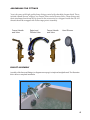
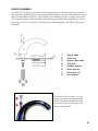
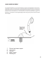
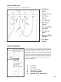
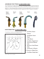
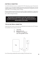
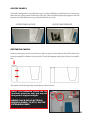
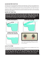
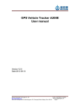
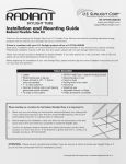
Installation and Operation
E
R
O
F
E
B
D
REA CKING!
A
UNP
Complies with
ADA
LISTED
Guidelines
CONTENTS
Introduction and Contact Information ................................... 3
Safety Instructions and Warnings ........................................ 4-5
INSTALLATION AND ASSEMBLY
Rough-In Dimensions .......................................................... 6
Location and Leveling .......................................................... 7
Assembling the Fittings........................................................ 8-13
Hose Connections ............................................................... 11-12
Drain Connection ................................................................. 11
Electrical Connection (Jetted Bathtubs Only) ............................ 14
Access Panels..................................................................... 15
Extension Panels................................................................. 15
OPERATION (Jetted Bathtubs Only)
Control Panel ....................................................................... 16-17
Inline Heater
Water Jets
CLEANING AND CARE
Cleaning and Care .............................................................. 18
FREQUENTLY ASKED QUESTIONS
FAQs ................................................................................... 19
WARRANTY AND RETURN INFORMATION
Warranty Information and Contact Policy ............................. 20
INTRODUCTION AND CONTACT INFORMATION
Congratulations on your Walk-In Bathtub purchase. We know you’ll enjoy
many years of comfort and convenience using it!
Great care has gone into the design of our walk-in tubs to simplify the
installation process, and to make the operation of your tub easy and troublefree.
This manual will explain basic installation techniques and cover the operation of your tub. Please read it completely before you or your installer begins
the installation process.
Each and every tub is thoroughly tested at the factory before shipping.
We’re confident that your Walk-In Bathtub sets the standard for comfort,
quality and durability. Should you have any questions, please contact us at:
Allure Walk-In Tubs
2340 W. Broadway Rd.
Suite 103
Mesa, Arizona 85202
Technical Support: Call toll-free (877) 629-5503
Be sure to keep your packing slip, delivery paperwork, order information
and any other documentation, so that it may be referenced if necessary.
3
INSTALLATION INSTRUCTIONS
UNPACKING AND MOVING YOUR TUB
Inspect the shipping carton prior to unpacking. Use caution with box cutters or razor knives.
In the unlikely event of damage which causes you to believe the bathtub inside may be damaged,
document the damage by taking a photograph of the damaged area, and immediately contact your
salesman or the company from which you purchased the tub.
When moving the tub prior to installation, carry the bathtub by its metal sub-frame. Do NOT lift or
carry the bathtub by the plumbing , air hoses, or deck. Carry or move the tub by holding the stainless
metal framework.
WARNING
When using electrical products, basic precautions should always be
followed, including the following:
DANGER: RISK OF ELECTRIC SHOCK. Connect only to a circuit protected by a Ground-Fault
Circuit-Interrupter.
Grounding is required. The unit should be installed by a qualified service representative and grounded.
Use of this unit is for its intended purpose only. Any attachments not included by the manufacturer
are prohibited.
Children, the elderly and the infirm should not use this unit without close and continuous supervision.
People using medications, pharmaceutical or natural supplements, sleep aids, or those with adverse
medical history should consult with a physician before using this product.
Water temperatures over 100 degrees Fahrenheit may pose a hazard to your health.
Use of your walk-in bathtub immediately after eating, or while under the influence of alcohol or
medication is not recommended. Alcohol or medication can cause drowsiness, loss of consciousness
and possible drowning.
Pregnant women should consult with a physician before using this bathtub.
In any bathtub, there is always the risk of electric shock by external appliances. Do not allow any
electric aplliances (hair dryers, fans, TV/radio, etc.) within 6 feet of this bathtub.
Do not operate without suction guard covers in place.
Installation must be done using a GFCI (Ground Fault Circuit Interrupter). Electrical and plumbing
connections shall meet all local codes.
4
IMPORTANT SAFETY INSTRUCTIONS
INSTRUCTIONS IMPORTANTES RELATIVES A
LA SECURITE
READ AND FOLLOW ALL INSTRUCTIONS
LIRE ET SUIVRE TOUTES LES INSTRUCTIONS
SAVE THESE INSTRUCTIONS
CONSERVER CES INSTRUCTIONS
WARNING: RISK OF ACCIDENTAL INJURY OR DROWNING; CHILDREN SHOULD NOT USE
HYDROMASSAGE BATHTUB WITHOUT ADULT SUPERVISION
AVERTISSEMENT: RISQUE DE BLESSURE ET DE NOYADE. NE PAS LAISSER UN ENFANT
UTILISER LA CUVE A REMOUS EN L’ABSENCE D’UN ADULTE.
WARNING: TO AVOID INJURY, EXERCISE CARE WHEN ENTERING OR EXITING THE
HYDROMASSAGE BATHTUB.
AVERTISSEMENT: POUR EVITER LES BLESSURES, USER DE PRUDENCE EN ENTRANT DANS
LA CUVE A REMOUS ET EN LA QUITTANT.
WARNING: RISK OF ELECTRIC SHOCK; DO NOT PERMIT ELECTRIC APPLIANCES (SUCH AS
A HAIR DRYER, LAMP, TELEPHONE, RADIO OR TELEVISION) WITHIN 1.5M OF THIS
HYDROMASSAGE BATHTUB.
AVERTISSEMENT: RISQUE DE CHOC ELECTRIQUE. NE PAS PLACER D’APPAREILS
ELECTRIQUES (LUMINAIRE, TELEPHONE, RADIO, TELEVISEUR, ETC.) A MOINS DE 1,5M
DE CETTE CUVE A REMOUS.
CAUTION: TEST THE GROUND FAULT CIRCUIT INTERRUPTER PROTECTING THIS
APPLIANCE PERIODICALLY IN ACCORDANCE WITH THE MANUFACTURER’S INSTRUCTIONS.
ATTENTION: VERIFIER REGULIEREMENT LE FONCTIONNEMENT DU DISJONCTEUR DE
FUITE A LA TERRE CONFORMEMENT AUX INSTRUCTIONS DU FABRICANT.
USERS RESIDING IN CANADA MUST INSTALL THIS UNIT IN ACCORDANCE WITH THE
CANADIAN ELECTRICAL CODE, PART 1.
LES UTILISATEURS RÉSIDANT AU CANADA DOIT INSTALLER CET APPAREIL SELON LE
CODE ÉLECTRIQUE CANADIEN, PARTIE 1.
5
ROUGH-IN DIMENSIONS
When installing tub, use galvanized screw or nail driven into wall stud to overlap tub flange as shown below
at left. Do NOT insert screw or nail through tub flange as shown below at right. This will weaken the
tub’s structure and void the warranty.
OK
1
2
3
4
5
1
NO!
2
Nail / screw
does NOT
pass through
tub flange,
damages
tub.
1.
2.
3.
4.
5.
Wall stud
Sheetrock
Nail or screw
Tile
Bathtub
3
Nail / screw
passes
through tub
flange,
damages
tub.
4
5
6
Note: Since no two customers’ installations will be identical,
these instructions are intended solely as a general reference.
Your installation may vary depending on your circumstances. Installations should be done by a licensed contractor or plumber,
and electrician.
LOCATION AND LEVELING
First, “test fit” the tub by placing it in the position where it will be installed. Be sure the tub’s
drain lines up with the floor drain, and note the position and length of the water inlet hoses*,
ensuring that they will reach the connecting points of your home’s water supply.
Once the tub is in place, it must be leveled. Do this by placing a carpenter’s level on the sides
and edge of the tub, and adjusting the feet. Adjust the feet by loosening the locknuts and
rotating the foot clockwise or counter-clockwise as needed, then tightening the locknuts. Although we check each tub at the factory, movement during shipping may cause adjustments
to be needed. Failure to properly level the tub may cause incomplete drainage, poor door seal
alignment, and other problems.
1. Place level on edge of tub.
2. Loosen locknuts on feet.
3. Rotate foot up or down
as needed to bring tub into
level position.
4. When tub is level, tighten
locknuts.
5. Repeat as necessary, until
all four edges of tub show
level.
*Water supply hoses not included.
7
ASSEMBLING THE FITTINGS
Your tub comes with high quality brass fittings coated with a durable chrome finish. These
include a Hand Shower, a Spigot, two Faucet Valves and a Diverter Valve. These fittings and
their attachment hardware can be found in the accessories box shipped inside the tub. All
threads should be wrapped with Teflon® tape prior to assembly.
Faucet Handle
and Valve
Spigot and
Diverter Valve
Faucet Handle
and Valve
Hand Shower
FAUCET ASSEMBLY
Assembly of the faucet and fittings (see diagram on next page) is simple and straightforward. The illustration
below shows a completed installation.
8
FAUCET ASSEMBLY (cont.)
To assemble the faucet valves, first install one rubber washer, steel washer, and retaining nut on faucet valve
body in order shown (parts 5,6 and 7). Push faucet valve body (3) from bottom through correct hole in tub
deck (4) and install second rubber washer, steel washer and retaining nut (5,6,7). Do not overtighten.
Screw on chrome retaining ring (2), being careful not to damage the tub’s finish. Attach faucet handle (1).
Note: It may be necessary to remove small plastic cap (8) in the side of the handle, to access the screw
which holds the faucet on. There is a hexagonal wrench provided in the faucet kit for this purpose. Repeat
procedure with second faucet valve.
1
1
8
8
5
6
7
7
6
5
2
2
4
4
3
3
1.
2.
3.
4.
5.
6.
7.
8.
5
6
7
7
6
5
Faucet handle
Chrome retaining ring
Faucet valve body
Tub deck
Retaining nut
Steel washer
Rubber washer
Cap and Attachment Screw
9
SPIGOT ASSEMBLY
Assembly of the spigot is as follows: Insert spigot body (1) and trim ring (2) from above
through hole in tub deck (4). Be sure locating pin (8) is aligned correctly with small hole in tub
deck. Install rubber washer (5) , steel washer (6) and retaining nut (7) on spigot valve body
(3). Thread the spigot valve body through trim ring and tighten into spigot body. Tighten
retaining nut. Do not overtighten. All threads should be wrapped with Teflon® tape prior to
assembly.
1
8
2
5
6
7
4
1.
2.
3.
4.
5.
6.
7.
8.
Spigot body
Trim ring
Spigot valve body
Tub deck
Rubber washer
Steel washer
Retaining nut
Locating pin
3
Operation of the Diverter Valve (to
change water flow from Spigot to Hand
Shower) is done by raising or lowering
the Diverter Stem on the rear of the
Spigot, as shown at left.
10
HAND SHOWER ASSEMBLY
To assemble the hand shower, insert chrome hand shower support (1) through tub deck (3) from above.
Install rubber washer (4) and retaining nut (5) on threaded portion of chrome hand shower support. Insert
flexible hand shower hose (not shown for clarity) through chrome hand shower support (1). Connect the
hand shower hose to the hand shower (1). Place hand shower (2) into chrome hand shower support. The
hand shower is designed to rest in an angled upright position when properly placed in the chrome hand
shower support.
2
Thread hand
shower hose
as shown
1
3
4
5
1.
2.
3.
4.
5.
Chrome hand shower support
Hand shower
Tub deck
Rubber washer
Retaining nut
11
HOSE CONNECTION
Connect hoses* as shown in the diagram below.
1. Cold Water
Faucet
2. Spigot/Diverter
1
5
2
4
3
6
3. Hot Water
Faucet
4. Hand Shower
8
9
5. Cold Water
Supply*
6. Faucet-to-Spigot
Line: Cold
7. Hand Shower
Hose
7
8. Faucet-to-Spigot
Line: Hot
9. Hot Water
Supply*
*Water supply hoses not included.
DRAIN CONNECTION
1
2
To
Overflow
Although drain connection may vary depending on
your circumstances, a typical installation is shown
at left. After the tub has been located over the existing drain, a “stub” is run up from the existing drain
in the floor. A threaded coupling is placed over the
stub, followed by a compression ring. Then the
threaded coupling is screwed onto the drain, forming a watertight seal.
3
4
5
1.
2.
3.
4.
5.
Tub Floor
Tub Drain
Compression Ring
Threaded Coupling
Existing “Stub” From Floor
12
ASSEMBLING THE FITTINGS: 46-INCH MODELS ONLY
The 46” bathtub uses a slightly different faucet configuration. Rather than a diverter within the
spigot, the diverter is a separate valve (see below). Installation and assembly is the same as
pages 8-10. These fittings and their attachment hardware can be found in the accessories box
shipped inside the tub. All threads should be wrapped with Teflon® tape prior to assembly.
Faucet
Handle
and Valve
Faucet
Handle
and Valve
Diverter
Valve
Spigot
Hand
Shower
HOSE CONNECTION - 46-INCH MODELS ONLY
Connect hoses* as shown in the diagram below.
1
6
2
7
3
4
Hot Water Faucet
3.
Cold Water Faucet
2.
4.
5.
6.
9
8
5
1.
10
11
7.
8.
9.
Diverter
Spigot
Hand Shower
Hot Water Supply Hose*
Hot Faucet to Diverter
Hose
Diverter to Hand Shower
Hose
Cold Faucet to Diverter
10. Diverter to Spigot Hose
11. Cold Water Supply Hose*
*Water supply hoses not included.
13
ELECTRICAL CONNECTION
Your Walk-In Bathtub functions on standard 110V-120V alternating current. The electrical
connection of your tub must be installed in accordance with the National Electrical Code and
with all local codes. It is highly recommended that your tub be wired on a separate circuit, with
a dedicated GFCI circuit breaker rated for 25 amps.
If the new circuit run exceeds 100 feet check with local codes for requirements. Any junction
box(es)installed should be moisture-proof, and unreachable while sitting or standing in the
tub, or while touching the faucet(s).
All electrical connections must be carried out by a
certified electrician in accordance with local electrical
requirements and codes.
TYPICAL ELECTRICAL CONNECTION
A typical electrical connection is shown below.A dedicated circuit is hardwired to a GFCI breaker.
Your installation must conform to local codes.
1.
2.
3.
Tub wiring
Dedicated circuit
Breaker box or subpanel
with 25-amp GFCI breaker
3
Tub
1
2
Note: Tub must be grounded and bonded according to local electrical codes.
14
ACCESS PANELS
Your tub is designed for a trouble-free service. In the unlikely event that service is necessary,
there are two access panels in the front of the tub. These are held in place by magnets, and can
be removed with the suction cup tool included with your tub.
ACCESS PANELS IN PLACE
ACCESS PANELS REMOVED
EXTENSION PANELS
In the event that you wish to install your tub in a space wider than the tub itself, there is an
extension panel kit inluded with your tub. Check the diagram and photos below for installation
The panels are held in place by metal clips, as shown below.
NOTE: The Extension Panels are for
aesthetic purposes only and are not
designed to support weight.
NEVER PLACE ANY ELECTRICAL
DEVICES (RADIO, TV, ETC.) ON THE
EXTENSION PANEL.
15
OPERATION
(Jetted Bathtubs Only)
CONTROL PANEL
Once your Walk-In Bathtub is assembled and installed the operation is simple. On the inside wall
of the tub you will see a control panel like the one
shown at right and below. There are three buttons
which control the functions of the tub.
On-Off Switch
Water
Jet
Switch
Air
Jet
Switch
First, turn on the power to the tub by pressing the On-Off button.
The indicator light on the button will illuminate, signifying that the tub has been turned on.
To activate the air jets, press the Air Jet switch.
To activate the water massage jets, press the Water Jet switch. Note: This will automatically
activate the Inline Heater function to help maintain the water temperature at a comfortable
level.
To turn off any or all functions, including the power, simply press the switch again.
All three buttons have indicator lights to show that they are in operation.
16
INLINE HEATER FUNCTION
The Inline Heater is pre-programmed to maintain a water temperature of 104o F. It is not designed to raise
the temperature of cold bathwater, but to maintain the water temperature while running the water jet
system. It is activated automatically when the water jet system is turned on, senses the current water
temperature, and turns on and off automatically as needed to maintain this temperature. Please note that the
Inline Heater will not operate unless the water jet system is turned on, as the water must circulate through
the heater for it to be effective.
WATER JET FUNCTION
NOTE: Ensure that the water level in the tub is above the sensors and
water jets in the back rest (see illustration). If water level is too low,
overspray may occur, or the water pump may not function.This is a
safety feature designed to prevent damage to the water pump.
CORRECT WATER LEVEL:
JETS FUNCTION CORRECTLY
WATER LEVEL TOO LOW:
OVERSPRAY FROM JETS
JETS
WATER LEVEL TOO LOW:
JETS WILL NOT FUNCTION
The sensors for the Water Pump are the small
silver studs located beneath the water jets on
the seat backrest.
AIR JET SYSTEM
The Air Jet system injects air into the bath from a number of fittings to create a soothing massage. The air
jets can be run in conjuction with the water jets or separately.
NOTE: After every bath, and after the bathtub has been drained, the
air jets should be run for 1 to 2 minutes, whether they were used
during the bath or not. This will clear the lines and prevent mildew.
17
CLEANING AND CARE
The water and air jet systems should be cleaned before first use and on a monthly basis afterwards while
the bathtub is in normal use.
WATER JET SYSTEM (Jetted Bathtubs Only)
1. Fill the tub with WARM water 2-3 inches above the jets. Add 1/4 to 1/2 box of baking soda to the
bathtub water.
2. Turn on jet massage system and run for 10 minutes.
3. Drain tub.
4. Fill tub with COLD water 2-3 inches above jets.
5. Turn on water jet system and run for 10 minutes.
6. Drain tub.
7. Run air jet system for 1-2 minutes to clear out lines.
8. Use a mild liquid household detergent such as or a spray-on aerosol cleaner designed for use on
fiberglass or acrylic tubs, and wipe with a clean soft cloth. A soft bristled brush may be used in the
textured areas of the slip-resistant floor if necessary.
SUCTION COVER (Jetted Bathtubs Only)
NEVER OPERATE THE WATER JET SYSTEM
WITH THE SUCTION COVER OFF!
Remove any hair, lint, or soap residue from the suction cover. An old toothbrush is especially good at
cleaning soap scum from the holes in the suction cover.
On a monthly basis, unscrew the suction cover and clean away any hair, lint or debris from the cover and
housing, then remount the cover in place.
SURFACE CLEANING
NEVER USE ABRASIVES OR POWDERED CLEANSERS. They will scratch and dull the surface.
Always use a mild liquid household detergent such as or a spray-on aerosol cleaner designed for use on
fiberglass or acrylic tubs. Test on a small area for the cleaner’s effect on the finish. DO NOT USE METAL
SCRAPERS, WIRE BRUSHES OR OTHER HARSH ABRASIVE TOOLS.
Never use bleach when cleaning the surface or the jet systems.
Light scratches and dulled areas may be restored to original luster by polishing with an automotive type
rubbing compound designed for use with fiberglass and gelcoat. Stubborn debris or construction adhesive
residue may be removed with denatured alcohol.
FADING
Avoid locating your bathtub where it will receive continuous direct sunlight. Continued exposure to the
sun’s UV rays can cause yellowing, fading or discoloration.
18
FREQUENTLY ASKED QUESTIONS
Q.
A.
Does the bathtub come with supply hoses?
These are not supplied with the tub. Hoses are available at any home supply or hardware store.
Q.
A.
What size threads are the faucet taps?
The faucet threads are all 1/2" NIP.
Q.
A.
Q.
A.
Q.
A.
Q.
A.
Q.
A.
Q.
A.
Q.
A.
Q.
A.
What if I am missing a part?
Carefully double-check all packaging and cartons. If you are still missing a part please call 877629-5503 and ask for the Parts Department.
There seems to be no power to the tub.
Check to be sure the top light ON/OFF on the keypad is ON (indicator light should be
illuminated).Check GFCI and/or Circuit Breaker. During initial Installation testing, if tub will not
operate be sure that the ground is dedicated and does not have any stray voltage present—this will
cause the control box not to energize.
The water jets (or air jets) do not come on.
Be sure there is power to the tub. (See question 4 above). If air jets operate but water jets do not,
be sure the water jet sensors are below the water level. (see page 17 of manual).
The bathwater does not stay warm.
The heater operates automatically when the water pump feature is turned on. If the water pump is
not on then the heater will not function. The heating system is designed to maintain water temperature of 104°. If water jets are on and temperature is not maintained, remove access panel and
check to be sure red light is illuminated on inline heater when water jets are in operation.
During cold winter months my tub will not fill up with enough hot water.
Home water heater capacity too small. Install a larger-capacity hot water heater, a fast-recovery
hot water heater, or an on-demand hot water heater.
How should I clean the tub?
See page 18 of manual.
What is the round chrome object in the bottom of the doorway?
This is a door drain, a safety feature which allows excess water to drain away from the doorway in
the event of a door seal leak, and to drain away standing water in the door sill after bathing.
Should I leave the bathtub door open or closed when I am not using it?
Always leave the door open when not in use. This prevents the door seal from becoming compressed over time, leading to premature failure. It can also prevent small pets from falling into the
tub and becoming trapped.
19
ALLURE WARRANTY POLICY
Allure® Bathroom Fixtures carry 5-year warranties. This is a manufacturer’s warranty, which covers the
mechanical and electrical assemblies of each bathroom fixture. There is a lifetime warranty on the door seal.
Installation and associated labor is the singular responsibility of the owner, not Allure. Any costs related to
installation and labor remain the responsibility of the owner and not Allure. If an electrical component
related to a bathroom fixture fails, the customer must utilize the services of a licensed electrician or electrical
contractor to verify this warranty claim. Any costs associated with the aforementioned testing requirement
remain the client’s full financial responsibility. If an installer has any questions prior to installation, Allure asks
the client to contact the tech department Monday-Friday (8:30am-4pm PST).
Allure’s Warranty Policy does not cover superficial fixtures and surfaces. It is the customer’s responsibility
to inspect a delivered product within 24 hours of receipt. If superficial damage is discovered, Allure must
be notified by phone: 877 629 5503. Additionally, this damage claim must carry accompanying digital
photographic images displaying said damage. If this damage claim is not filed within 24 hours of receipt, the
customer will be responsible for the price of the part and variable shipping rate. 24 hours represents the
standard period to file concealed damage claims with LTL and specialty shipping companies used by
Allure.
Allure maintains a parts department and associated parts in stock. Parts are shipped Monday-Friday
during regular shipping hours (10am-3pm PST). Standard parts are shipped standard ground. Larger parts
are shipped via LTL freight. If the customer chooses to expedite the shipment of an in-stock part, he or she
is responsible for the associated variable fee. If a part is on backorder, it may not re-enter stock for 2.5-8
weeks. If a backorder part(s) is needed immediately the customer can request air shipment from our
manufacturing facilities and will be responsible for variable international shipping rates. Air Shipped parts
can require 1-3 weeks for production.
ATTENTION
Please contact ALLURE® WALK-IN TUBS if any items are missing, misplaced or
defective, or if you have any questions or concerns with your product. We will be glad
to assist you promptly.
You may contact one of our friendly and helpful representatives at 1-877-629-5503
Monday through Friday, from 8:00 AM to 5:00 PM, Pacific Standard Time. We will
respond rapidly to provide a solution.
Thank you for your business and please enjoy your new Allure® Walk-In Bathtub!
20
Technical Support: Call toll-free (877) 629-5503