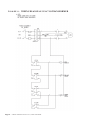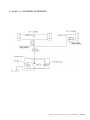
1
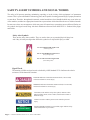
XL, X3W & X4W Series Scissor Lifts with Tilt Installation, Operation and Service Manual Model Number ___________________ Serial # _________________________ Date placed in service _____________ IMPORTANT: READ CAREFULLY BEFORE INSTALLING OR OPERATING LIFT Part orders are subject to a $50 minimum charge. September 2014 This manual was current at the time of printing. To obtain the latest, most updated version, please contact Presto Lifts Customer Service Department or go to our website: www. 3UHVWR/LIWVFRP\RXZLOO¿QGDFRPSOHWHOLVWRIFXUUHQW owner’s manuals to print. Page 2 — PRESTO OWNER’S MANUAL: XL, X3W & X4W SERIES CONTENTS S E C T I O N 1: Introduction .............................................................................................................4 Responsibility of Owners and Users .......................................................................5 Safety Alert Symbols and Signal Words .................................................................6 S E C T I O N 2: Safety ......................................................................................................................7 S E C T I O N 3: Installation...............................................................................................................8 A. Inspection ...........................................................................................................8 B. Installing .............................................................................................................8 C. Electricals ...........................................................................................................8 D. Hydraulics ..........................................................................................................9 E. Testing the Lift with No Load ............................................................................9 S E C T I O N 4: Operation.................................................................................................................9 A. Method of Operation ..........................................................................................9 B. Operating Procedures ........................................................................................9 S E C T I O N 5: Maintenance ..........................................................................................................10 A. Routine Maintenance......................................................................................10 B. Troubleshooting Maintenance ........................................................................10 S E C T I O N 6: Service................................................................................................................... 11 A. Replacing Cylinder Seals .................................................................................11 B. Replacing Leg Rollers ......................................................................................12 LIST OF FIGURES: Figure 1. Maintenance Chock .........................................................................................11 Figure 2. XL Scissor Lifts ................................................................................................13 Figure 3. Exposed Cylinder Assembly ............................................................................15 Figure 4. Exposed Power Pack ........................................................................................15 Figure 5. Wiring Schematic 115/1/60 power with 20 AMP Plug ....................................16 Figure 6. Wiring Schematic 208, 220, 460/3/60 Power with Pig Tail ............................17 Figure 7. Hydraulic Schematic for all Models .................................................................18 Figure 8. Labeling Diagram for all Models .....................................................................19 Figure 9. X4WT36-20......................................................................................................20 Figure 10. X3WT36 .........................................................................................................21 Figure 11. Wiring Diagonal 115 AC no Transformer.......................................................22 Figure 12. Plumbing Schematic .......................................................................................23 RECOMMENDED SPARE PARTS LIST ........................................................................14 RESTOCKING POLICY .................................................................................................24 RETURN GOODS AUTHORIZATION (RMA) PROCEDURES ...................................25 ORDERING REPLACEMENT PARTS ...........................................................................26 WARRANTY ....................................................................................................................27 PRESTO OWNER’S MANUAL: XL, X3W & X4W SERIES — Page 3 SECTION 1 INTRODUCTION This manual attempts to provide all of the information necessary for the safe and proper installation, operation and maintenance of Presto Lifts Inc. XL, X3W or X4W Series Scissor Lifts. It is important that all personnel involved with the installation, maintenance or operation of the scissor lift read this manual. Where unique situations arise, that are not covered in this manual, call Presto Lifts for further instructions. Additional manuals are available upon request or on our web site at www.prestolifts.com. 7KHVFLVVRUOLIWKDVDQDPHSODWHWKDWSURYLGHVWKHORDGFDSDFLW\UDWLQJVVHULDOQXPEHUDQGPRGHOLGHQWL¿FDWLRQV Please refer to these numbers when ordering parts or requesting further information. The Presto Lifts XL, X3W or X4W lifts are designed for lifting, lowering and positioning a variety of loads. WHERE UNIQUE SITUATIONS ARISE, THAT ARE NOT COVERED IN THIS MANUAL, CALL PRESTO LIFTS FOR FURTHER INSTRUCTIONS. The XL, X3W or X4W Series is designed for inplant/nonhazardous location use only. These units are not for personnel lifting. Page 4 — PRESTO OWNER’S MANUAL: XL, X3W & X4W SERIES Responsibility of Owners and Users Inspection and Maintenance The device shall be inspected and maintained in proper working order in accordance with Presto’s owner’s manual. Removal from Service Any device not in safe operating condition such as, but not limited to, excessive leakage, missing rollers, pins, or fasteners, any bent or cracked structural members, cut or frayed electric, hydraulic, or pneumatic lines, damaged or malfunctioning controls or safety devices, etc. shall be removed from service until it is repaired to the original manufacturer’s standards. Repairs $OOUHSDLUVVKDOOEHPDGHE\TXDOL¿HGSHUVRQQHOLQFRQIRUPDQFHZLWK3UHVWR¶VLQVWUXFWLRQV Operators Only trained personnel and authorized personnel shall be permitted to operate PowerStak. Before Operation Before using the device, the operator shall have: Read and/or had explained, and understood, the manufacturer’s operating instructions and safety rules. Inspected the device for proper operation and condition. Any suspect item shall be carefully exDPLQHGDQGDGHWHUPLQDWLRQPDGHE\DTXDOL¿HGSHUVRQDVWRZKHWKHULWFRQVWLWXWHVDKD]DUG$OO LWHPVQRWLQFRQIRUPDQFHZLWK3UHVWR¶VVSHFL¿FDWLRQVKDOOEHFRUUHFWHGEHIRUHIXUWKHUXVHRIWKH PowerStak. During Operation The device shall only be used in accordance with this owner’s manual. Do not overload. Ensure that all safety devices are operational and in place. 0RGL¿FDWLRQVRU$OWHUDWLRQV 0RGL¿FDWLRQVRUDOWHUDWLRQVWRDQ\3UHVWRLQGXVWULDOSRVLWLRQLQJHTXLSPHQWVKDOOEHPDGHRQO\ZLWK written permission from Presto. PRESTO OWNER’S MANUAL: XL, X3W & X4W SERIES — Page 5 SAFETY ALERT SYMBOLS AND SIGNAL WORDS The safety of all persons operating, maintaining, repairing, or in the vicinity of this equipment is of paramount concern. This is a powerful machine with moving parts, and is capable of causing personal injury if proper precautions DUHQRWWDNHQ7KHUHIRUHWKURXJKRXWWKLVPDQXDOFHUWDLQKD]DUGVKDYHEHHQLGHQWL¿HGZKLFKPD\RFFXULQWKHXVH of the machine, and there are appropriate instructions or precautions which should be taken to avoid these hazards. In some cases, there are consequences which may occur if instructions or precautions are not followed. Below are WKHV\PEROVDQGVLJQDOZRUGVDORQJZLWKWKHLUGH¿QLWLRQVUHIHUHQFHGIURP$16,=3URGXFW6DIHW\6LJQV and Labels. Safety Alert Symbols These are the safety alert symbols.. They are used to alert you to potential physical injury hazards. Obey all safety messages that follow this symbol to avoid possible injury or death. For use with DANGER signal word (Red Background) For use with WARNING signal word (Orange Background) For use with CAUTION signal word (Yellow Background) Signal Words 7KHPHDQLQJRIGLIIHUHQWVLJQDOZRUGVDVGH¿QHGE\$16,6WDQGDUG=LQGLFDWHVWKHUHODWLYH seriousness of the hazardous situation. DANGER indicates a hazardous situation which, if not avoided, will result in death or serious injury. (Red Background) WARNING indicates a hazardous situation which, if not avoided, could result in death or serious injury. (Orange Background) (Yellow Background) CAUTION, used with the safety alert symbol, indicates a hazardous situation which, if not avoided, could result in minor or moderate injury. NOTICE is used to address practices not related to personal injury. (Blue Background) SAFETY INSTRUCTIONS SAFETY INSTRUCTIONS (or equivalent) signs indicate safetyrelated instructions or procedures. (Green Background) Page 6 — PRESTO OWNER’S MANUAL: XL, X3W & X4W SERIES SECTION 2 SAFETY The safety of all persons installing, using, servicing, or working near the unit is of paramount concern to Presto Lifts. The lift is a powerful machine with moving parts, and is capable of causing personal injury if proper precautions are not taken. Therefore, throughout this manual, Presto Lifts has identi¿HGFHUWDLQKD]DUGVZKLFKPD\RFFXULQWKHXVHRIWKHXQLWDQGSURYLGHGDSSURSULDWHinstructions or precautions that should be taken to avoid these hazards. In some cases, Presto Lifts’ has also pointed out the consequences that may occur if Presto Lifts’ instructions or precautions are not followed. Presto Lifts uses the following nationally recognized system for identifying the severity of the hazards associated with its products: DANGER – Immediate hazard that will result in severe personal injury or death. WARNING – Hazard or unsafe practice, that could result in severe personal injury or death. CAUTION – Hazard or unsafe practice, that could result in minor personal injury or property damage. In the interest of safety, please read the entire manual carefully. You must understand the material in this manual before you install, use, or service the unit. If you have any question about any of the instructions in this manual, please contact Presto Lifts Inc. at 1-800-343-9322. PRESTO OWNER’S MANUAL: XL, X3W & X4W SERIES — Page 7 SECTION 3 INSTALLATION Upon receipt of the XL, X3W or X4W Series Scissor Lift, inspect the equipment completely to determine if there is any shipping damage, and that the lift is complete. Presto Lifts Inc. tests and inspects every piece of equipment prior to shipment. If damage is apparent, DIUHLJKWFODLPPXVWEH¿OHGZLWKWKHIUHLJKWFRPSDQ\ Do Not use the lift if there appears to be any damage. With the lift in a collapsed position, check the following: d). If the lift is provided with anchor holes or brackets, be sure the lift has been placed in the exact operating position before spotting or drilling holes for anchor bolts. Bolt the lift securely before using it. e). For lifts with remote power units, locate and bolt the power unit in place, so as to provide easy access. Do not obstruct the operator's work area. Make hydraulic connections according to the information contained in Section 3D. f). Electrical connections must be made according to the electrical schematics and information contained in Section 3C and in compliance to local codes and ordinances. Check for signs of damage especially to the electrical and hydraulic components. Check all connections for tightness. Is there K\GUDXOLFÀXLGYLVLEOH" &KHFNEDVHIUDPHIRUÀDWQHVV Inspect for any bent or damaged metal parts. 1. Pit Mounted Installation a). Build pit to standard pit dimension as outlined in Figure 2, Page 6, paying careful attention to raceway, sump, clearance and height requirements. b). The remaining steps are the same as required for ÀRRULQVWDOODWLRQ6HH6HFWLRQ%EWRI A. INSPECTION: B: INSTALLING Before starting, be sure that the electrical system is wired and is in full compliance with local electrical codes and ordinances. Read all of the instructions prior to starting the lift. 1. Floor Installation D0DNHVXUHWKDWWKHÀRRULQWKHLQVWDOODWLRQDUHDLV level, stable and free from dirt and surface defects. b). Place lift in exact operating position. WARNING! Do not install lifts in pits unless they have approved bevel edge top or electro-mechanical toe guards. CAUTION! Lifts with toeguard and oversized platforms must be secured with at least 4 anchor bolts with a minimum of 2000-lb pullout strength for each bolt. C. ELECTRICALS: CAUTION! When moving the lift, do not ever attempt to pick it up by the platform. The lift should be picked up by the base frame only. The use of a strap sling is suggested. If the lift has optional lifting eyebolts, attach a chain spreader and raise the lift from a center position. Be sure the eyebolts are secured in place with locking nuts prior to lifting. The motors on XL, X3W or X4W Scissor Lifts are special intermittent duty motors with high pull up torques. These motors require heavier duty electrical controls than standard motors. c). Make sure that the complete base of the lift is in conWDFWZLWKWKHÀRRU,QRUGHUWRSURYLGHFRPSOHWHFRQWDFW ZLWKWKHÀRRUWKHEDVHPD\EHVKLPPHGRUJURXWHG The following chart recommends power sources for various motors supplied with Scissor Lifts. CAUTION! Do not spot shim. The complete base must be in FRQWDFWZLWKWKHÀRRURUVKLPV Page 8 — PRESTO OWNER’S MANUAL: XL, X3W & X4W SERIES CAUTION! All wiring must conform to local codes and must be performed by licensed electricians. E. TESTING THE LIFT WITH NO LOAD: MOTOR SIZE FUSE BREAKER 1 HP 120 Volt 1 PH 25 AMP 20 AMP 25 AMP 20 AMP 208-20 Volt 3 PH 15 AMP 10 AMP 1 HP 240 Volt 1 PH 1-1/2 HP 1-1/2 HP 460 Volt 3 PH 7-1/2 AMP 5 AMP Schematics for wiring motors: Figure 6 for 120 volt 1 PH Figure 6 for 240 volt 1 PH Figure 7 for 208/240/460 volt 3 PH WARNING! Do not tamper with or remove cover of the electrical MXQFWLRQER[2QO\DXWKRUL]HGTXDOL¿HGSHUVRQQHO should service the electrical system. D. HYDRAULICS: 1. Use hydraulic oil only for the lift. The lift has been supplied with Conoco Super Hydraulic 32. 2. Before using the lift, check the hydraulic oil level DQGDGGRLOLIQHFHVVDU\&KHFN¿WWLQJVIRUWLJKWQHVV 3. External power pack units also require that the hydraulic lines be blown out with clean air. Then attach WRK\GUDXOLF¿WWLQJVSHUK\GUDXOLFVFKHPDWLF)LJXUH CAUTION! XL, X3W or X4W Scissor Lifts are designed for normal factory environments. Where below freezLQJFRQGLWLRQVPD\H[LVWVSHFLDOÀXLGPXVWEHXVHG Contact Presto Lifts for further information when freezing conditions exist. WARNING! Do not use automotive hydraulic, brake or transPLVVLRQ ÀXLGV7KH\ ZLOO GDPDJH VHDOV DQG SRVH D VHULRXV¿UHKD]DUG 1. Before testing the lift, clear the area of any loose material. Be sure the lift has no obstruction above it or RQDQ\VLGH8VLQJWKHFRQWUROVSURYLGHGEULHÀ\RSHUate the lift (5-10 seconds). If the lift begins to rise with a humming sound and functions properly, continue to the full upright position. CAUTION! If the lift does not rise immediately, or there is any operational problem, stop it immediately. Before continuing, check the rotation of the pump and moWRUDQGWKHYROWDJHDWPRWRUWHUPLQDOVDJDLQEULHÀ\ operate the lift. If the lift does not move smoothly with a humming sound, stop and review the procedures in the section on troubleshooting (5B). 2. After raising the lift completely, lower the lift. It should move slowly and smoothly without a humming sound. If the lift operates properly, raise and lower the lift and stop at different levels to get a good perspective on the lift's operations and movements. SECTION 4 OPERATION A. METHOD OF OPERATION: All XL, X3W or X4W Scissor Lifts are provided with a special relief valve and are factory preset for the maximum safe capacity of the lift. Activating and holding the up switch will energize the motor. The motor is attached to a positive displacement pump, that draws K\GUDXOLFÀXLGIURPWKHUHVHUYRLUDQGWUDQVIHUVLWXQGHU pressure to the cylinder. This forces the piston forward and the scissor legs to separate and raise the platform, releasing the up button will stop the lift. A check valve between the pump and piston holds the table in position. Depressing and holding the down switch will energize a solenoid, that allows the oil from the cylinder to return WRWKHUHVHUYRLUWKURXJKDSUHVHWÀRZFRQWURO7KLVDOlows the lift to lower smoothly and at a controlled speed. B. OPERATING INSTRUCTIONS: In order to operate the lift follow these operating procedures. PRESTO OWNER’S MANUAL: XL, X3W & X4W SERIES — Page 9 Read and understand all the instructions before operatLQJ,IWKHOLIWKDVPRGL¿FDWLRQVRUDFFHVVRULHVUHDGDQG understand their functions. performing any maintenance, shut the power off. Then raise the top over its center position, secure in place and perform the routine listed (1 through 7). 1). Load the lift correctly. a). Do not load the lift while it is running. b). Do not exceed the maximum rated load (note that load capacity is reduced due to side or end loading.) c). Place load in the center of table. d). If the load is unstable or may become unstable, fasten it into position. For lifts with oversized or beveled edge platforms, the lift must be serviced in an up position. The following procedure must be followed prior to servicing: 2). Operate the lift. a). To raise the lift, press and hold the up button. b). To lower the lift, press and hold the down button. c). Release the button to stop the lift. 3). Wait until the lift has come to a complete stop before unloading the lift. 4). Stand clear of lift when operating it in order to avoid injury. WARNING! a). Do not stand, sit or climb onto the lift. b). Do not load or unload a moving lift. c). If the lift fails to move or exhibits strange movements or sound, stop immediately. Do not operate the lift until it has been checked and repaired. d). Obey all warning labels. SECTION 5 MAINTENANCE Generally, the XL, X3W or X4W Series Scissor Lifts require very little maintenance. Reasonable care will result in excellent trouble-free performance. WARNING! Never go under or service lift with a load on the table or with the scissor mechanism unblocked. Always service the lift in a down position. A. ROUTINE MAINTENANCE: All routine maintenance should be performed monthly and can be performed on the standard XL, X3W or X4W Series Scissor Lifts in a lowered height position. Before Page 10 — PRESTO OWNER’S MANUAL: XL, X3W & X4W SERIES a). Raise the lift to the full up position. b). Place the safety chock in position as shown in Figure 1. c). Lower the lift until the wheels come in contact with the chock. d). Shut the power off. e). Perform the routine listed (1 through 7). WARNING! Wood blocks should be cut to the proper length and be of a hard wood variety such as oak or ash. Check for defects or damage to the blocks prior to each usage. These blocks are to be used only if the maintenance chock has been damaged or misplaced. 1). Check oil level. Add oil if necessary. 2). Check rollers for signs of wear. Replace if damaged. 3). Check snap ring and shield. Replace if damaged. 4). Check hydraulic lines for damage or leaking. Replace if damaged. &KHFNIRURLOVSRWVRQWKHÀRRU7UDFHOHDNVWRWKH SURSHU¿WWLQJDQGWLJKWHQ 6). Check wiring for damage. Replace immediately if any sign of wear is evident. 7). Bearings on these lifts are permanently lubricated and require no servicing. Look for any signs of wear. 8). Check that all pre-cautionary labeling is in place and legible. Replace damaged labels immediately. See Figure 8. B. TROUBLESHOOTING MAINTENANCE: LIFT WILL NOT MOVE: 1. No operational noises: a). Check power switch, fuses and overloads. b). Check voltage at motor -- motor may have failed. 2. Operational noises: a). Lift may be overloaded or jammed. Check load weight and obstructions. b). Motor (3 phase) single phasing. Check voltage at motor terminals. c). Motor (3 phase) reversed. Reverse 2 lines. d). Motor (1 phase) low voltage. Check voltage at motor terminal. e). Oil shortage -- reservoir low or oil line failure. Repair or replace. f). Down valve open, check wiring, remove and run lift. 3. Motor overheats: a). Excessive cycle rate (15 per hour max.). b). Low voltage -- check voltage at motor. F2LOVWDUYDWLRQFKHFN¿OWHULQUHVHUYRLU 3. 4. LIFT OPERATING SLOWLY: 1. Up cycle: D2LOVWDUYDWLRQFKHFN¿OWHULQUHVHUYRLU b). Oil viscosity -- oil is too heavy or too thin. c). Air in cylinder -- cycle lift with no load 2 times and hold down button for 20 seconds after bottoming out on each cycle. 2. Down cycle: a). Down valve dirty -- remove and clean. Check oil condition, replace if dirty. b). Pinched hydraulic lines. c). Oil viscosity is too heavy. 3. Lift raises, then slowly lowers without power: a). Down valve dirty. Remove and clean. E/HDNLQJK\GUDXOLFOLQHVRU¿WWLQJVFKHFNIRU telltale oil spots). c). Check valve in pump -- may not be seating. Requires new pump. 4. Lift will not lower when energized: a). Down solenoid faulty. Check voltage -- may be low or wrong voltage for coil. Check continuity of coil (burned out). 8. 9. 10. 11. 12. 5. 6. 7. Disconnect the electrical power. Disconnect the hydraulic hose from the cylinder DQGFDSWKHOLQHWRSUHYHQWK\GUDXOLFÀXLGORVV Loosen the set screws holding the cylinder pin. Remove the cylinder pin. Lift the cylinder out of the lift. CAUTION! Hold the cylinder securely while removing the pin WRSUHYHQWLWIURPIDOOLQJWRWKHÀRRU 13. 14. 15. 16. 17. 18. 19. 20. 21. 22. 23. Clamp cylinder securely at the base end. Completely collapse cylinder piston. Push gland into the cylinder 1/8''- 3/16''. Remove retaining ring. Remove piston rod, piston and gland from cylinder. Remove rod nut, piston and gland. Remove and replace seals and wipers. Assemble piston and gland to piston rod. Assemble rod nut to piston rod and torque to 100 ft./lb. Lubricate piston and seals and install cylinder. Insert retainer ring. Install cylinder and hydraulic lines. Fill reservoir. a). For the lifts serviced in lowered position, lower tabletop completely. b). For the lifts serviced in the up position, raise table and remove chocks. Cycle lift 2-3 times adding oil if necessary. Recheck reservoir oil level. F I G U R E 1: MAINTENANCE CHOCK SECTION 6 SERVICE A. REPLACING CYLINDER SEALS: (Seal kits are listed on page 11) 1. 2. Lower the lift to its lowest position and hold down switch for an additional 10 to 20 seconds. Then lift the top to its over center position and secure. For lifts with oversized platforms, the cylinder is replaced while the lift is in an up position. To position lift in the up position, follow instructions for routine maintenance (5A a-e). PRESTO OWNER’S MANUAL: XL, X3W & X4W SERIES — Page 11 A. REPLACING LEG ROLLERS (Seal kits are listed on page 11) 1. 2. 3. 4. 5. 6. a). For standard lifts, lower lift to is lowest position and hold down switch for an additional 10-20 seconds. Then lift the top to its over center position and secure. b). For lifts with oversize or beveled platform secure the lift as follows: Raise the lift to its full raised position. Place a steel 7/8'' or 1'' bar through both outer scissor leg holes. Lower the lift until WKHLQQHUOHJVDUH¿UPO\LQFRQWDFWZLWKWKHEDU Disconnect electrical power. Raise the leg assembly 2'' and support with the yellow supplied safety chock. Remove retainer clips, shield and rollers. Clean and lubricate axle. Replace with new rollers, shields and clips. a). For lifts serviced in a lowered position lower the tabletop completely. b). For lifts serviced in the up position, raise table slightly and remove steel bars. Page 12 — PRESTO OWNER’S MANUAL: XL, X3W & X4W SERIES F I G U R E 2: XL SCISSOR LIFTS ITEM # DESCRIPTION 1 Foot Control 2 Down Solenoid Coil 3 Pump 4 Motor 5 Roller 6 Suction Line 7 Pressure Line 8 Control Panel 9 Fill Plug 10 Upper Roller 11 Cylinder 12 Vent 13 Roller Chock PRESTO OWNER’S MANUAL: XL, X3W & X4W SERIES — Page 13 RECOMMENDED SPARE PARTS LISTING Description Part # Used On: Model Foot Switch E308-E36 All Units Down Solenoid 2562028 115 VAC Phase Power Lift, Coil Only 2562029 208, 220, 460, 1 & 3 Phase Power Lift, 24V Coil Only 2562033 Valve Stem Only 1000-034-10 1 GPM. All 24'' Travel Series. All 36'' Travel Series with 2000, 3000 and 4000 Capacities 1000-034-20 2 GPM. All 36'' Travel Series with 5000 and 6000 Capacities. All 48'' Travel Series. E255R 1HP 1PH. All 24'' Travel Series. All 36'' Travel Series with 2000, 3000 and 4000 Capacities. E255T 1.5 HP 3PH. All 36'' Travel Series with 5000 and 6000 Capacitities. All 48'' Travel Series. Roller Kit 1000-067VR* All Units Hose Hydraulic High Pressure Contact Presto Parts XL24 Series, X3W24 Seris, X4W24 Series Hose Hydraulic Low Pressure 80000006VR All Units, except X3W & X4W Junction Box EX 281 All Units (115V only) Reservoir Fill Plug 2946097 XL24 only. All others use #2904415 Cylinder 1000-018 (3-1/2'' bore) All 36'' travel lists with 2000, 3000, 4000, 5000 and 6000 capacity (not XT36-40) 1000-019 (4" bore) XL36-40 Only 1000-020 (4'' bore) XL24-40 Only 1000-021 (3-1/2'' bore) All 24'' travel lifts with 2000, 4000 and 6000 capacity (not XL24-40) 1000-023 (3-1/2'' bore) All 48'' travel lifts with 2000, 4000 and 6000 capacity Cylinder Vent Plug 1016-089 XL24 Series, XL48-20, XL48-40 Maintenance Chock 1000-234-01VR XL24 Series, X3W24 Seris, X4W24 Series Flow Control Valve B211RC-A All Units Hydraulic Safety Fuse 1000-086 All Units Cylinder Seal Kit 1000-059-01 For All 3-1/2'' bore Diameter Cylinders. 1000-059-02 For All 4'' bore Diameter Cylinders Pendant E307 NEMA 1-115 Volt AC 25 AMP Transformer E306 All units with non-115 voltage Contactor E305-24 All units with non-115 voltage Reservoir 1000-196-01VR All 36" Travel Units 1000-196-02VR All 48" Travel Units 1022-025VR All 24" Travel Units 1000-046 All Units Pump Motor Reservoir Filter *For machines purchased 2006 & before: 1000-067VR. For machines purchased 2007 & up, contact Parts Dept. with model and serial number of machine. Page 14 — PRESTO OWNER’S MANUAL: XL, X3W & X4W SERIES F I G U R E 3: EXPOSED CYLINDER ASSEMBLY ITEM # DESCRIPTION 1 Cylinder 2 Velocity Lock or Excess Flow Protector 3 Roller 4 Wheel Chock F I G U R E 4: EXPOSED POWERPACK ITEM # DESCRIPTION 1 Motor 2 Pump 3 Reservoir 4 Fill Plug 5 Control Box PRESTO OWNER’S MANUAL: XL, X3W & X4W SERIES — Page 15 F I G U R E 5: WIRING SCHEMATIC 115/1/60 power with 20 AMP PLUG Page 16 — PRESTO OWNER’S MANUAL: XL, X3W & X4W SERIES F I G U R E 6: WIRING SCHEMATIC 208, 220, 460/3/60 POWER with PIG TAIL PRESTO OWNER’S MANUAL: XL, X3W & X4W SERIES — Page 17 F I G U R E 7: HYDRAULIC SCHEMATIC for all MODELS Page 18 — PRESTO OWNER’S MANUAL: XL, X3W & X4W SERIES F I G U R E 8: LABELING DIAGRAM for all MODELS PRESTO OWNER’S MANUAL: XL, X3W & X4W SERIES — Page 19 F I G U R E 9: X4WT36-20 Page 20 — PRESTO OWNER’S MANUAL: XL, X3W & X4W SERIES F I G U R E 10: X3WT36 Plain View Shown with lift fully lowered & partial view of tilt top in phantom PRESTO OWNER’S MANUAL: XL, X3W & X4W SERIES — Page 21 F I G U R E 11: WIRING DIAGONAL 115 AC NO TRANSFORMER Page 22 — PRESTO OWNER’S MANUAL: XL, X3W & X4W SERIES F I G U R E 12: PLUMBING SCHEMATIC PRESTO OWNER’S MANUAL: XL, X3W & X4W SERIES — Page 23 PARTS Standard parts may be returned with a 20% restocking fee or $35.00 net, whichever LVJUHDWHU0RGL¿HGRUFXVWRPHQJLQHHUHGSDUWVDUHQRWUHWXUQDEOH8QIRUWXQDWHO\ GXHWRSRWHQWLDOO\FRQFHDOHGGDPDJHDOOVDOHVRIHOHFWULFDODVVHPEOLHVDUH¿QDO QUALITY ISSUES Should you feel there is a quality problem, please contact the seller to ask questions and gather information on how to rectify the issue. Presto Lift Inc. reserves the right to determine potential credits, as a result of factory defects, based on its inspection of the merchandise. GENERAL All products shipped from our factory have passed Quality Assurance inspection and testing. The carrier of choice has signed for, and accepted the product in new working condition. The customer should inspect to ensure it is not received damaged, has no concealed damage or is not incomplete. Parts orders are determined to be complete based upon Presto Lift, Inc. inspection sheets and carrier shipping weights. Page 24 — PRESTO OWNER’S MANUAL: XL, X3W & X4W SERIES RETURN GOODS AUTHORIZATION POLICY 3UHVWR/LIWVSURYLGHVWKH5HWXUQ*RRGV$XWKRUL]DWLRQ5*$3ROLF\IRUVSHFL¿FPRGHOVDVD courtesy to our distributors in the event they do not receive what they ordered. If a customer wishes to return a Presto Lifts product, please contact the Customer Service Department and UHTXHVWDQ5*$QXPEHU7KLVUHTXHVWPXVWEHPDGHRQRUEHIRUHWKH¿IWHHQWKFDOHQGDUGD\ following the date of Presto Lifts’ invoice for the merchandise. Not all units are returnable. Quantity orders and special designs cannot be returned under any circumstances. Presto CusWRPHU6HUYLFHUHVHUYHVWKHULJKWIRU¿QDOMXGJPHQWRQDOOSURGXFWUHWXUQV The RGA number must appear on the outside of any packaging material for a return to be accepted and processed by Presto Lifts. Customers shipping returns from the Continental US, Canada, or Mexico have thirty (30) days from date of RGA issue to have the product arrive at Presto Lifts’ facility. All merchandise must arrive Free on Board at Presto Lifts’ facility or the shipment will be refused and returned to the sender. All credits are issued less restocking and refurbishing charges, regardless if the merchandise was damaged in transit. Return addresses: please refer to your RMA for the address to which your product should be returned. Presto Lift Inc. 715 Highway 77 Manila, Arkansas 72442 Telephone: 800-343-9322 Fax: 888-788-6496 PRESTO OWNER’S MANUAL: XL, X3W & X4W SERIES — Page 25 Ordering Replacement Parts Presto Lifts has carefully chosen the components in your unit to be the best available for the purpose. Replacement parts should be identical to the original equipment. Presto Lifts will not be responsible for equipment failures UHVXOWLQJIURPWKHXVHRILQFRUUHFWUHSODFHPHQWSDUWVRUIURPXQDXWKRUL]HGPRGL¿FDWLRQVWRWKHXQLW Presto Lifts can supply all replacement parts for your lift. With your order, please include the model number DQGWKHVHULDOQXPEHURIWKHXQLW<RXFDQ¿QGWKHVHQXPEHUVRQWKHQDPHSODWH7KLVSODWHLVORFDWHGZLWKLQ the scissors mechanism. To order replacement parts, please call the Presto Parts Department. Parts are shipped subject to the following terms: )2%IDFWRU\ 5HWXUQVRQO\ZLWKWKHDSSURYDORIRXUSDUWVGHSDUWPHQW &UHGLWFDUGVSUHIHUUHGH[FHSWSDUWVFRYHUHGE\ZDUUDQW\ )UHLJKWFROOHFWIRUWUXFNH[FHSWSDUWVFRYHUHGE\ZDUUDQW\ )UHLJKW±SUHSDLGDQGLQYRLFHIRUVPDOOSDUFHOVKLSPHQWVH[FHSWSDUWVFRYHUHGE\ZDUUDQW\ Parts replaced under warranty are on a “charge-credit” basis. We will invoice you when we ship the replacement part, then credit you when you return the worn or damaged part, and we verify that it is covered by our warranty. Labor is not covered under warranty for Parts orders. Presto Parts Department 50 Commerce Way Norton, MA 02766 Telephone: 800-343-9322 FAX: 888-788-6496 Email: [email protected] www.PrestoLifts.com Page 26 — PRESTO OWNER’S MANUAL: XL, X3W & X4W SERIES Presto Lifts Limited Warranty Policy Presto Lifts warrants all of its products against defects in the welded structural frame and, if apSOLFDEOHVFLVVRUOHJVIURPIDXOW\PDWHULDODQGZRUNPDQVKLSIRUDSHULRGRI¿YH\HDUVIURP the date of invoice. All other components have a limited warranty against defects in faulty material and workmanship for a two (2) year period from the date of invoice date of invoice and 30 day limited warranty on labor. Please note that prior authorization from Presto Lifts is required on all warranty work. 7KHUHDUHQRLPSOLHGZDUUDQWLHVRIDQ\NLQGPRUHVSHFL¿FDOO\WKHUHDUHQRZDUUDQWLHVRIPHUFKDQWDELOLW\RU¿WQHVVIRUDQ\SDUWLFXODUSXUSRVH3UHVWR/LIWV VROHZDUUDQW\VKDOOEHDVVHWIRUWK in this limited warranty. Presto Lifts will elect to repair or replace a defective component without charge, if any components should become defective within the limited warranty period. Proof of purchase is required for warranty. The charge for shipping the defective component is the responsibility of the buyer and must be accompanied with an RMA number. The shipping charge to return the component to the buyer is the responsibility of Presto Lifts, Inc. This limited warranty does not cover labor expense for removal or reinstallation of components after thirty days. This limited warranty shall not cover, among other things: damages resulting from foreign matter or water, failure to provide reasonable and necessary maintenance, and if applicable, use of product while charger is plugged into an AC outlet, or failure to follow operating instructions. The limited warranty is not valid for damage resulting from negligence, accident, unreasonable use, abuse or misuse, exceeding data plate capacities or altering the product without Presto Lifts authorization. Presto Lifts expressly disclaims and excludes any liability for consequential, incidental, indirect RUSXQLWLYHGDPDJHVRU¿QDQFLDOORVVWRSHRSOHRUSURSHUW\UHVXOWLQJIURPDQ\EUHDFKRIZDUUDQW\ or the operation or failure of this product. Presto Lifts makes no representation that this product complies with local, state, or federal safety/ product standards codes. Should this product fail to comply in any way with those codes, it shall not be considered a defect of materials or workmanship. Presto Lifts shall not be held liable for any damages resulting from noncompliance. It is the dealer's responsibility to exercise this limited ZDUUDQW\7KLVOLPLWHGZDUUDQW\LVSURYLGHGWRWKHRULJLQDOSXUFKDVHUGH¿QHGDVWKHRULJLQDOHQG XVHUDQGLVQRQWUDQVIHUDEOH7KLVFRQVWLWXWHVWKHFRPSOHWHDQG¿QDODJUHHPHQWLQYROYLQJ3UHVWR Lifts and limited warranty obligations for products. PRESTO OWNER’S MANUAL: XL, X3W & X4W SERIES — Page 27 MANY NEEDS REQUIRE MANY OPTIONS... LET PRESTO MEET THOSE NEEDS! Call Presto Sales for stock or customized lift inquiries: 800-343-9322 Email: [email protected]