1
GEO T Series
T4805 5° Tangent Array Module
T2815 15° Tangent Array Module
CD18 Directional Sub-bass
User Manual
Page 2/63
INTRODUCTION
GEO Technology is radically new thinking
The GEO R&D Project has, to date, resulted in the following patent applications:
•
The GEO Hyperboloid Reflective Wavesource™ differs radically from the megaphone-variant
type horns you know and love (or hate). “Tried and true” methods will produce entirely
unexpected results. HRW technology produces precise and predictable results.
•
The Configurable Directivity Flange. A waveguide that allows the operator to alter its behaviour.
An unprecedented NEXO development that is easy to use – once you know how and when.
•
The Directivity Phase Device needs no operator input to function, but it is reassuring to know that
the coupling of the midrange of the system is considered as important as the high frequencies…
•
GEO’s DSP-driven Cardioid Dipolar Sub-bass devices are a new approach to controlling LF/VLF
acoustic energy.
GEO is not hard to use when you understand how…
The technology behind GEO is revolutionary, but it is grounded in years of practical experience with the
problems of delivering high quality professional sound to large audiences at high SPL levels. The GEO
toolbox includes GEOSoft -a simple yet powerful and highly predictive design tool. The array assembly
system is keyed to the design software and will easily enable you to deploy your design with great
precision. The NX242 Digital TDcontroller provides driver protection and system optimization as well as
DSP-driven cardioid pattern control for the T4805 Tangent Array Module and the CD18 Cardioid Dipole
Sub-bass.
GEO is a high precision system
The GEO HRW™ controls acoustic energy more precisely than other multiple element waveguides. It
also makes GEO less forgiving of mistakes. Whilst conventional horns never combine into a coherent
array, they may deliver acceptable results even if the design and deployment of the system is less than
optimal. This is not the case with GEO where careless installation produces catastrophic results.
A GEO Tangent Array is not a “line array”
GEO Technology is equally effective in designing and deploying tangent horizontal arrays or curved
vertical arrays. For best results in a specific application the user needs to know how multi-speaker
arrays interact with audience geometry, along with the benefits and drawbacks of curved vertical arrays
and horizontal arrays.
Curved vertical tangent arrays require different design techniques
For the past 20 years, sound reinforcement professionals have worked with horizontal arrays that use
conventional horns to deliver [more or less] ‘equal power to equal angles’. Curved vertical arrays are
designed to deliver [more or less] equal power to equal areas’. When arrays use conventional horns,
the lack of precision, overlap and interference masks errors in array design and aiming. The highly
precise GEO wavesource responds accurately, consistently and predictably to the design and
deployment of a curved vertical tangent array. This is why the GEO rigging system is designed to
control angular splay to 0.01° precision.
GEO curved vertical tangent arrays require different operational techniques
Over the years, system designers and operators have developed a number of signal processing
techniques to disguise and partly overcome the limitations of horn design. “Frequency shading,”
“amplitude shading,” “system tuning,” all of these are tools of the advanced sound system operator.
NONE OF THESE TECHNIQUES ARE APPLICABLE TO GEO TANGENT ARRAYS. Instead of
enhancing the array’s performance they will severely degrade it.
Take time to learn how to get great results with GEO Technology. It is an investment that will pay off in
more satisfied clients, more efficient operating procedures and more recognition for your skill as a
sound system designer and operator. A comprehensive understanding of GEO theory, tangent arrays,
and specific features of the GEO T Series will help you to operate your system at its full potential.
GEO T Series User Manual V1.04
Date: 22/12/2005
INTRODUCTION
Page 3/63
TABLE OF CONTENTS
1
2
Introduction....................................................................................................................... 4
GEO T General Set-up Instructions .................................................................................. 6
2.1
Speaker Wiring .......................................................................................................... 6
2.2
Amplifier Selection..................................................................................................... 8
2.3
Current rating ............................................................................................................ 9
2.4
Amplifier settings .......................................................................................................9
2.5
Example .................................................................................................................. 10
3 GEO T rigging procedure................................................................................................ 12
3.1
SAFETY FIRST ....................................................................................................... 12
3.2
General Description................................................................................................. 14
3.3
“Tension Mode” Setup ............................................................................................. 15
3.4
“Compression Mode Full Kelping Beam” Setup....................................................... 22
3.5
“Compression Mode – Half Kelping Beam” Setup ................................................... 29
3.6
Testing and Maintenance of the system .................................................................. 36
4 NEXO NX242 Digital Controller for GEO T..................................................................... 37
4.1
NX242 Proprietary Functions .................................................................................. 37
4.2
Cardioid LF and VLF ............................................................................................... 38
4.3
GEO T NX242 Setups description ........................................................................... 39
4.4
Trouble shooting...................................................................................................... 40
4.5
Delays & System alignment..................................................................................... 41
4.6
Driving the CD18s from the AUX send .................................................................... 42
5 GEO T Tangent Array System Check List ...................................................................... 44
5.1
Are the NX242 Digital TDcontrollers properly configured? ...................................... 44
5.2
Are the amplifiers properly configured? ................................................................... 44
5.3
Are the amps and the NX properly connected?....................................................... 44
5.4
Are the speakers properly connected and angled ? ................................................ 45
5.5
Final Pre-Sound Check Check ................................................................................ 45
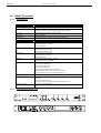
6 Technical Specifications ................................................................................................. 46
6.1
GEO T4805 Vertical Tangent Array Module ............................................................ 46
6.2
GEO T2815 Vertical Tangent Array Module ............................................................ 48
6.3
CD18 Directional Sub-Bass..................................................................................... 50
6.4
GEO T Rigging system............................................................................................ 52
6.5
NX242 TDcontroller ................................................................................................. 54
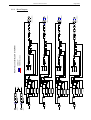
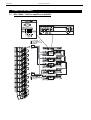
7 Connection diagrams...................................................................................................... 56
7.1
GEO T4805 / T2815 to amplifiers and NX242 ......................................................... 56
7.2
CD18 to amplifiers and NX242 ................................................................................ 57
8 GEO T Series Parts & Accessories List.......................................................................... 58
8.1
Array Modules & Control Electronics List ................................................................ 58
8.2
Accessories List ...................................................................................................... 58
9 Recommended installation tools and equipment ............................................................ 60
10
USER NOTES............................................................................................................. 61
Page 4/63
1
INTRODUCTION
INTRODUCTION
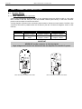
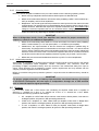
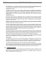
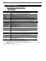
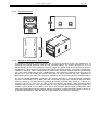
Thank you for selecting a NEXO GEO T Series Tangent Array .System This manual is intended to
provide you with necessary and useful information about your GEO System, which includes the
following products:
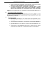
750 mm
[29.53"]
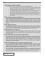
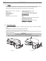
•
T4805 5° Tangent Array Module. 4x 8”
(20cm) Neodymium Hi-flux 16 Ohm LF
Drivers (two forward-facing LF/MF, two rearfacing LF) and one 3” voice coil, 1.4” Throat
Neodymium 16 Ohm HF Driver with a 5°
Hyperboloid Reflective Wavesource™. The
main building block for curved vertical
tangent arrays.
•
T2805 15° Tangent Array Module. 2 x 8”
(20cm) Neodymium Hi-flux 16 Ohm LF
Drivers (forward-facing LF/MF), 2 x rear
passive acoustic resistance radiator and a 3”
voice coil, 1.4” Throat Neodymium 16 Ohm
HF Driver with a 15° Hyperboloid Reflective
Wavesource™. The near-field building block
for curved vertical tangent arrays.
•
CD18 Cardioid Dipole Sub-bass. Two 18”
(45cm) Long Excursion Neodymium 6 Ohm
Drivers, each controlled by one DSP
channel, producing a 110° x 110° SuperCardioid pattern. Can be used in flown or
ground-stacked configurations.
750 mm
[29.53"]
1200 mm
[47.24"]
•
NX242 Digital TDcontroller. Provides comprehensive control of GEO T Series loudspeakers in
multiple configurations. For a complete description of this unit, please refer to the NX242 User
Manual. The NX242 DSP algorithms and parameters are fixed in software and are updated
regularly: please consult the NEXO web site (www.NEXO.fr or www.NEXO-sa.com) for the latest
software releases.
INTRODUCTION
•
•
Page 5/63
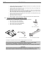
GEO Array Flying System. A fully integrated and
accurate flying system that provides safe, flexible and
simple means of flying GEO Tangent Arrays. NOTE:
GEO Tangent Arrays control the dispersion of acoustic
energy with a high degree of precision. Inclinometers
and laser aiming tools are essential to ensure proper
audience coverage when installing a GEO Tangent
Array.
GEOSoft Array Design Software simplifies the design
and implementation of vertical tangent GEO arrays.
Please consult the NEXO web site (www.NEXO.fr or
www.NEXO-sa.com) for the latest software releases.
Please devote your time and attention to reading this manual.
A comprehensive understanding of GEO theory, tangent
arrays, and specific features of the GEO T Series will help
you to operate your system at its full potential.
Page 6/63
2
GEO T GENERAL SET-UP INSTRUCTIONS
GEO T GENERAL SET-UP INSTRUCTIONS
2.1
Speaker Wiring
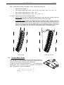
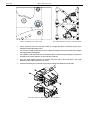
2.1.1
GEO T4805 & T2815 connectors
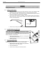
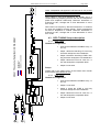
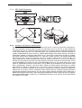
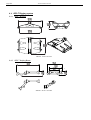
GEO T’s are connected to power amplifiers via one AP6 Male Connector (GEOT-612M) on a link cable
that is stowed in the rear vent port. One EP6 Female Chassis (GEOT-613F) on the back connector
panel is used as output to feed the next GEO T.
A wiring diagram is printed on the connection panel located on the back of each cabinet. The EP6 / AP6
connectors are linked in parallel within the enclosures (see the Connections Diagrams section of this
manual).
EP6/AP6 Pin #
GEO T4805
1/2
3/4
5 / 6-
Rear 8” LF - 32 Ω
Front 8” LF/MF - 32 Ω
1.4” HF – 16 Ω
1 Negative – 2 Positive
3 Negative – 4 Positive
5 Negative – 6 Positive
GEO T2815
Not connected
Front 8” LF/MF – 32 Ω
1.4” HF – 16 Ω
Through
3 Negative – 4 Positive
5 Negative – 6 Positive
IMPORTANT
NEVER USE a male connector to feed the signal:
High voltages and currents are delivered from the amplifiers to the GEO T system.
1
2
3
4
5
6
BACK BACK +
FRONT FRONT +
HF HF +
GEO T4805 REAR CONNECTOR PANEL
GEO T2815 REAR CONNECTOR PANEL
GEO T GENERAL SET-UP INSTRUCTIONS
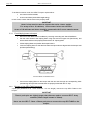
2.1.2
Page 7/63
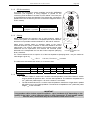
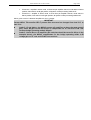
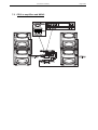
CD18 connectors
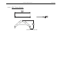
The CD18 are connected to power amplifiers via NL4FC SPEAKON
connectors (not supplied). A wiring diagram is printed on the
connection panel located on the back of each cabinet. The in/out pins
of the SPEAKON sockets are identified. The sockets are connected in
parallel within the enclosures (see the Connections Diagrams section
of this manual).
Front
Back
NL4FC #
1- / 1+-
2.1.3
2- / 2+
Rear 18” VLF - 8 Ω
Front 18” VLF - 8 Ω
1(-) Negative – 1(+) Positive
2(-) Negative – 2(+) Positive
CD18
Cabling
NEXO recommends the exclusive use of multi-conductor cables to
connect the system: the cable kit is compatible with all the cabinets,
and there is no possible confusion between LF, MF and HF sections.
Cable choice consists mainly of selecting cables of the correct
sectional dimension (size) in relation to the load resistance and the
cable length. Too small a cable section will increase both its serial
resistance and its capacitance; this reduces the electrical power
delivered to the loudspeaker and can also induce response (damping
factor) variations.
CD18 REAR CONNECTOR
PANEL
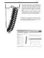
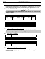
For a serial resistance less or equal to 4% of the load impedance (damping factor = 25), the maximum
cable length is given by:
Lmax = Z x S
S in mm2, Z in Ohm, Lmax in meters
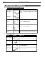
The table below indicates these values, for 3 common sizes.
2.1.4
Load Impedance (Ω)
2
Cable section
Maximum Length (meters)
3
4
6
8
12
16
1,5 mm² (AWG #14)
3
4.5
6
9
12
18
24
2,5 mm² (AWG #12)
5
4 mm² (AWG #10)
8
7.5
10
15
20
30
40
12
16
24
32
48
64
Examples:
•
The GEO T4805 LF section has a 32 Ohm nominal impedance, so 6x GEO T4805 LF section
wired in parallel will present a 32/6 = 5.3 Ohm load impedance. The maximum acceptable 2x2.5
mm2 (AWG #12) cable length Lmax for such a cluster is 13.25 meters.
•
The CD18 subwoofer has a 2 x 8 Ohm nominal impedance, therefore 2 CD18s wired in parallel
will present a 2 x 4 Ohm load impedance. The maximum acceptable 2x4 mm2 (AWG #10) cable
length Lmax is then 16 meters.
IMPORTANT
Long speaker cables induce capacitive effects – up to hundreds of pF depending on the
quality of the cable - with a high-pass effect on high frequencies. If long speaker cables
must be used, ensure that they do not remain coiled while in use.
Page 8/63
GEO T GENERAL SET-UP INSTRUCTIONS
2.2
Amplifier Selection
NEXO recommends high power amplifiers in all cases. Budget constraints are the only reason to select
lower power amplifiers. A lower power amplifier will not reduce the chances of driver damage due to
over-excursion, and may actually increase the risk of thermal damage due to sustained clipping. If an
incident occurs on an installation without protection, the fact that amplifiers only generating half their
rated output power (-3dB) are used will not change anything in respect of possible damage. This is due
to the fact that the RMS power handling of the weakest component in the system is always 6 to 10 dB
lower than the amplifier rating.
2.2.1
GEO T4805 recommended amplification
GEO T4805 is rated for very high power handling and has a 16 Ohm (HF) or 32 Ohm (LF Rear / LF/MF
Front) nominal impedance.
These high impedance values allow connection of up to 6 cabinets in parallel for each amplifier channel.
For such setup :
2.2.2
•
HF section: NEXO recommends that the amplifier should be capable of delivering 2700 Watts
into a 3 Ohm load.
•
LF Rear section: NEXO recommends that the amplifier should be capable of delivering 5200
Watts into a 6 Ohm load (typically the same amplifier as for the HF section but in Bridged Mono
mode)
•
LF/MF front section: NEXO recommends that the amplifier should be capable of delivering 5200
Watts into a 6 Ohm load (typically the same amplifier as for the HF section but in Bridged Mono
mode).
GEO T2815 recommended amplification
GEO T2815 is rated for very high power handling and has a 16 Ohm (HF) or 32 Ohm (LF/MF) nominal
impedance.
These high impedance values allow connection of up to 6 cabinets in parallel for each amplifier channel
For such setups:
2.2.3
•
HF section: NEXO recommends that each amplifier channel should be capable of delivering
2700 Watts into a 2 Ohm load.
•
LF/MF section: NEXO recommends that the amplifier should be capable of delivering 5200 Watts
into a 4 Ohm load (typically the same amplifier as for the HF section but in Bridged Mono mode).
CD18 Power recommended amplification
The CD18 requires two amplifier channels delivering separately processed signals to produce its
directional pattern.
NEXO recommends that each amplifier channel dedicated to CD18 should be capable of delivering
1000 to 2000 Watts into an 8 Ohm load.
Using the same amplifier model as those used for the GEO T will allow connection of up to 2 CD18 in
parallel to one amplifier (Stereo Mode).
GEO T GENERAL SET-UP INSTRUCTIONS
2.3
Page 9/63
Current rating
It is very important that the amplifier behaves correctly under low load conditions. A speaker system is
reactive by nature: on transient signals like music it will require four to ten times more instantaneous
current than its nominal impedance would indicate. Amplifiers are generally specified by continuous
RMS power into resistive loads, however the only useful information about current capacity is the
specification into a 2 Ohm load. It is possible to perform an amplifier listening test by loading the amps
with twice the number of cabinets considered for the application (2 speakers per channel instead of one,
4 instead of 2) and running the amps up to the onset of clipping. If the signal does not noticeably
deteriorate, the amplifier is well adapted (overheating after approximately ten minutes is normal but
thermal protection must not operate too quickly after starting this test).
2.4
Amplifier settings
2.4.1
Gain value
Gain is the key to correct alignment of the system. It is especially important to know the gain of all
amplifiers used in your set-up. The tolerance should be about ±0.5 dB. In practice this can be difficult to
achieve because:
•
Some amplifier brands have an identical input sensitivity for models of different power rating (this
infers a different voltage gain for each model). For example, a range of amplifiers with different
power outputs, all having a published input sensitivity of 775mV/0dBm or 1.55V/+6dBm, will have
a wide range of actual gains – the higher the power, the greater the gain.
•
Various other brands may offer constant gain but only within a given product range, for example
they may fit fixed input sensitivity only on their semi-professional amps.
•
Even if a manufacturer applies the constant gain rule to all models, the value selected will not
necessarily be the same as that chosen by other manufacturers.
•
Some products can exhibit manufacturing tolerances for the same model of ±1dB or more. Some
amplifiers may have been modified, possibly without any label indicating the new values. Others
may have gain switches fitted internally where it is impossible for the user to verify the actual
setting without opening the amplifier casing.
•
In cases where you don't know the gain of your amplifier (or want to check it) please follow this
procedure:
1) Unplug any loudspeakers from the amplifier outputs
2) With a signal generator, feed a sine wave at 1000Hz at a known voltage (say 0.5V) to
the input of the amplifier under test
3) Measure the voltage at the output of the amplifier
4) Calculate the gain using the formula Gain = 20 * LOG10(Vout/Vin).
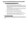
Some examples:
GainVin
20dB
26dB
32dB
37dB (1.4V sensitivity / 1350Wrms)
0.1V
1V
2V
4V
7.1V
0.5V
5V
10V
20V
35.4V
1V
10V
20V
40V
70.8V
Remember that constant sensitivity settings will give a different gain value when the amplifier power is
different.
NEXO recommends low gain amplifiers: +26dB is recommended, as it is at the same time adequately
low and quite common amongst amplifier manufacturers. This gain setting improves signal to noise ratio
and allows all preceding electronic equipment, including the NX242 TDcontroller, to operate at optimum
level. Remember that using a high gain amplifier will raise the noise floor proportionally.
Page 10/63
2.4.2
GEO T GENERAL SET-UP INSTRUCTIONS
Operating Mode
Most two channel amplifiers available on the pro-audio market have the following operating modes:
•
Stereo: two fully independent channels deliver identical power into identical loads
•
NEXO recommends Stereo Mode for HF sections when paralleling 6 GEO T series modules (2 x
6 HF per amplifier), and for CD18 amplification.
•
Bridge-Mono: the second signal channel processes the same input as the first channel, but with
reversed phase. The (single) load is connected between the two positive channel outputs using a
suitable connection. While the total output of the amplifier remains the same, the available output
voltage, the minimum impedance that can be connected and the voltage gain are doubled as
compared with stereo operation. Typically, only channel 1 input is active. Positive and negative
output connections vary depending on amplifier manufacturers.
IMPORTANT
When in Bridge-Mono mode, check your amplifier user manual for proper connection of
outputs 1(+) and (2+) in relation to input phase.
2.4.3
•
NEXO recommends Bridge Mono Mode for LF Rear and LF/MF Front sections when paralleling
6 GEO T series modules (1 x 6 LF rear per amplifier, 1 x 6 LF/MF front per amplifier).
•
Parallel-mono: the output terminals of the two channels are configured in parallel using an
internal relay. The (single) load is connected either to the output of channel 1 or to that of channel
2 (as if in stereo). While the total output of the amplifier remains the same the output voltage level
is also the same as in stereo mode. The minimum impedance that can be connected is reduced
by half due to the fact that current capability is doubled. Typically, only channel 1 input is active.
•
NEXO does not recommend Parallel-Mono Mode for any GEO T or CD18 amplification.
Advanced protection
Some high-end amplifiers may include signal processing functions similar to those found in the NX242
TDcontroller ("loudspeaker offset integration", "limiter", "compressor," etc.). Moreover, when this
processing is digital, computation latency time can introduce a few milliseconds delay from input to
output. These functions are not adapted to specific system requirements and may interfere with the
complex protection algorithms used in the NX242.
NEXO do not advise using other protection systems in conjunction with the NX242 and they should be
disabled.
IMPORTANT
For proper system protection, no latency time should be introduced between the output
of the NX242 TDcontroller and the input of loudspeakers through use of DSP modules
such as internal amplifier signal processing.
2.5
Example
For a 12 GEO T4805 and 4 CD18 cluster, and considering an amplifier model which is capable of
delivering 1 x 6000W into 4 Ohm or 2 x 3000W into 2 Ohm or 2 x 2000W into 4 Ohm, NEXO
recommends the following quantities and settings:
•
HF: 1 amplifier, 6 x GEO T4805 HF per channel, mode switch in Stereo position, Gain switch in
26 dB gain position, all dynamic or filter processing switches off.
•
LF/MF front: 2 amplifiers, 6 x GEO T4805 LF/MF per amplifier, mode switch in Bridge Mono
position, Gain switch in 26 dB gain position, all dynamic or filter processing switches off.
•
LF rear: 2 amplifiers, 6 x GEO T4805 LF Rear per amplifier, mode switch in Bridge Mono
position, Gain switch in 26 dB gain position, all dynamic or filter processing switches off.
GEO T GENERAL SET-UP INSTRUCTIONS
Page 11/63
•
CD18 rear: 1 amplifier in stereo mode, 2 CD18 rear per amplifier channel, mode switch in Stereo
position, Gain switch in 26 B gain position, all dynamic or filter processing switches off.
•
CD18 front: 1 amplifier in stereo mode, 2 CD18 front per amplifier channel, mode switch in
Stereo position, Gain switch in 26 B gain position, all dynamic or filter processing switches off.
Which gives a total of 7 identical amplifiers for such a cluster.
IMPORTANT
Former NX241 TDcontroller GEO T presets Gain structure has changed from load 2.13 to
load 2.14.
•
Loads 2.13 and below: the NX242 expects all amplifiers to have the same overall
gain; add 6 dB gain to the HF section to compensate for LF rear and LF/MF rear
sections bridge operating mode 6 dB gain.
•
Loads 2.14 and above: all amplifier gain switches should be set at 26 dB (as in the
example above); the NX242 compensates for the bridge operating mode 6 dB
voltage gain on LF rear and LF/MF front sections.
Page 12/63
3
GEO T RIGGING PROCEDURE
GEO T
RIGGING PROCEDURE
Before proceeding with assembly of GEO T arrays, please ensure that the components are present and
undamaged. A component list is appended to this manual. In the event of any shortage, please contact
your supplier.
For maximum efficiency the GEO T rigging system requires three experienced persons for set-up:
typically one motor hoist operator, and one GEO T operator per side of the array. Good synchronisation
and crosscheck between the operators are key elements for a reliable and safe set-up.
3.1
SAFETY FIRST
GeoT / CD18 Rigging System has been approved by Certification Organization RWTÜV. Structural
computations, test reports, certificates are available in Geosoft2 or at Nexo ([email protected]) upon
request.
We include this section to remind you of safe practice when flying the GEOT / CD18 system. Please
read it carefully. However, user must always apply his or her knowledge, experience and common
sense. If in any doubt, seek advice from your supplier or NEXO agent.
This manual offers guidance only for GEOT / CD18 loudspeaker systems. References in this manual to
other rigging equipment such as motor hoists, steels, shackles etc. are made to clarify the description of
GEOT / CD18 procedures. The user must ensure that operators are properly trained by other agencies
in the use of these items.
The GEOT / CD18 Rigging System has been optimised for the deployment of curved vertical tangent
arrays of GEO T4805 / T2815 / CD18 loudspeakers. Vertical angle adjustment between cabinets has
been limited to specific settings to ensure correct acoustic coupling.
The GEOT / CD18 Rigging System is a professional precision tool set, and should be handled with
extreme care. Only persons who are fully conversant with the operation of the GEOT / CD18 Rigging
System and provided with suitable safety equipment should deploy GEO Arrays. Misuse of the GEOT /
CD18 Rigging System could lead to dangerous consequences.
Used and maintained correctly, the GEOT / CD18 Rigging System will give many years of reliable
service in portable systems. Please take the time to read and understand this manual. Always use
GEOSoft2 to determine the optimum angle settings for a particular venue, hang point and curved
vertical GEOT / CD18 array. Applied forces and moments are strongly cabinet quantity and angle
configuration dependent. Cluster configuration must be implemented and validated in Geosoft2 prior to
installation.
3.1.1
Flown Systems Safety
•
Always inspect all the rigging components and cabinets for damage before assembly. Pay
special attention to the lifting points, and safety clips. If you suspect that any of the components
are damaged or defective, DO NOT USE THE AFFECTED PARTS. Contact your supplier for
replacements.
•
Read this manual carefully. Also be familiar with the manuals and safe working procedures for
any ancillary equipment that will be used with the GEOT / CD18 Rigging System.
•
Applied forces and moments are strongly cabinet quantity and angle configuration dependent.
Cluster configuration must be implemented and validated in Geosoft2 prior to installation.
•
Ensure that all local and National regulations regarding the safety and operation of flying
equipment are understood and adhered to. Information on these regulations can usually be
obtained from Local Government Offices.
•
When deploying a GEOT / CD18 system always wear protective headwear, footwear and eye
protection.
•
Do not allow inexperienced persons to handle a GEOT / CD18 system. Installation personnel
should be trained in loudspeaker flying techniques and should be fully conversant with this
manual.
GEO T RIGGING PROCEDURE
3.1.2
Page 13/63
•
Ensure that motor hoists, hoist control systems and ancillary rigging components are currently
certified as safe and that they pass a visual inspection prior to use.
•
Ensure that public and personnel are not allowed to pass beneath the system during the
installation process. The work area should be isolated from public access.
•
Never leave the system unattended during the installation process.
•
Do not place any object, no matter how small or light, on top of the system during the installation
procedure. The object may fall when the system is flown and is likely to cause injury.
•
Secondary safety steels must be installed once the system has been flown to the operating
height. Secondary steels must be fitted irrespective of requirements of the local safety standards
applicable to the territory.
•
Ensure that the system is secure and prevented from pivoting around the motor hoist.
•
Avoid any form of excessive dynamic loading to the assembly (structural computations on GeoT
Rigging System are based on a 1/1.2 factor for hoist or motor acceleration).
•
NEVER attach any item to the GEOT / CD18 system other than the GEOT / CD18 accessories.
•
When flying outdoor systems ensure that the system is not exposed to excessive wind or snow
loads and is protected from rainfall.
•
The GEOT / CD18 Rigging System requires regular inspection and testing by a competent test
centre. NEXO recommend that the system is load tested and certified annually or more
frequently if local regulations require.
•
When de-rigging the system ensure that the same duty of care is given to the procedure as for
the installation. Pack GEOT / CD18 components carefully to prevent damage in transit.
Ground Stacking Safety
Statistically, many more injuries occur due to unstable ground stacked PA systems than those
associated with flown systems. There are several reasons for this fact, however the message is clear:
•
Always survey the supporting structure upon which a ground stack is to be built. Always look
beneath PA wings to inspect the deck support and if necessary ask for the stage scrims and
dressings be removed to allow access.
•
If the stage surface slopes, as it does in some theatres, ensure that the system is prevented from
sliding forwards due to vibration. This may require the fitting of timber battens to the stage floor.
•
For outdoor systems ensure that that the system is protected from wind forces which might
cause the ground stack to become unstable. Wind forces can be huge, especially upon large
systems, and should never be underestimated. Observe meteorological forecasts, calculate the
“worst case” effect upon the system prior to erection and ensure that the system is secured
appropriately.
•
Take care when stacking cabinets. Always employ safe lifting procedures and never attempt to
build stacks without sufficient personnel and equipment.
•
Never allow anyone, whether operators, artists or members of the public to climb onto a ground
stacked PA system. Anyone who needs to climb over 2m high should be fitted with suitable safely
equipment including a clip-on harness. Please refer to local Health and Safety legislation in your
territory. Your dealer can help with advice on access to this information.
•
Apply the same attention to all safety matters when de-stacking systems.
•
Be aware that safety procedures are as important in the truck and in the warehouse as they are
at the venue.
Page 14/63
3.1.3
GEO T RIGGING PROCEDURE
Contacts
Correct training is fundamental to safe practise when working with loudspeakers flying systems. NEXO
recommend that users contact local industry associations for information on specialist course.
Information for International training agencies can be obtained by contacting either:
The Production Services Association
(PSA),
School Passage,
Kingston-upon-Thames,
KT1 SDU Surrey,
ENGLAND
Telephone: +44 (0) 181 392 0180
Rigstar Training and Testing Center
82 Industrial Dr. Unit 4
Northampton, Massachusetts 01060 U.S.A.
Phone: 413-585-9869 -- Fax: 413-585-9872
[email protected]
ESTA
Entertainment Services & Technology Association
875 Sixth Avenue, Suite 1005
NEW YORK, NY 10001 USA
Phone: 212-244-1505 – Fax: 212-244-1502
[email protected] - www.esta.org
3.2
General Description
Each GEO T Array Module includes an individual rigging system, which is mounted at the NEXO
factory.
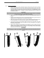
Six BLGEOT12-30 push-pins are provided with the GEO T4805.
Four BLGEOT12-30 push-pins are provided with the GEO T2815.
All holes on GEO T side rigging plates are 12mm diameter, matching the push-pins which are 12mm
diameter x 30mm length.
IMPORTANT
Provided push-pins are specifically rated.
Never use other push-pins than the ones provided with the GEO T components
GEO T2815
GEO T4805
GEO T RIGGING PROCEDURE
Page 15/63
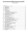
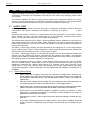
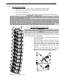
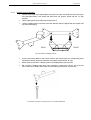
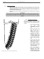
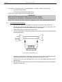
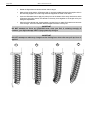
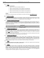
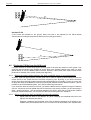
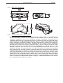
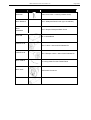
GEO T angle sequences follow logarithmic scales. Angle setting values are:
•
Bumper to GEO T4805 : 0°
•
GEO T4805 to GEO T4805: 0.125° - 0.20° - 0.315° - 0.50° - 0.80° - 1.25° - 2.0° - 3.15° - 5.0°
•
GEO T4805 to GEO T2815: 6.30° - 8.00° - 10.0°
•
GEO T2815 to GEO T2815: 6.30° - 8.00° - 10.0° - 12.5° - 15°
The GEO T rigging system has two operating modes:
•
Tension mode: the force of gravity sets angles between upper and lower cabinets. When the
array is lifted into position each cabinet opens automatically to the correct angle.
•
Compression mode: pull-back force applied between the extreme bottom cabinet and the top
bumper set angles between cabinets. When the array is lifted into position all cabinets are at 0°
and it is only when the pull-up force is applied that the correct angles are obtained. Compression
mode can be applied either with articulated kelping beam (“Compression Mode – Full Kelping
Beam”) or with fix beam and chain lever hoist (“Compression Mode – Half Kelping Beam”).
911 mm
[35.87"]
310 mm
[12.20"]
TENSION MODE
3.3
839 mm
[33.03"]
“Tension Mode” Setup
Tension mode is restricted to small bumper initial angle settings (+/~10°, depending on configuration), and does not require any other
accessory than the GEO T bumper (GEOT-BUMPER).
In order to increase initial angle settings to +/- ~15° (depending658
onmm
[25.91"]
configuration), GEO T bumper can be connected to front beam of
GEO T Kelping Beam (GEOT-KELPBEAM).
COMPRESSION MODE
Page 16/63
GEO T RIGGING PROCEDURE
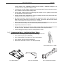
To be lifted in tension mode, the GEO T bumper requires either:
•
one motor hoist and a bridle;
•
or two motor hoists (easier initial angle setting);
In both cases, ensure that the motors are properly rated.
IMPORTANT
Motor hoists must be rated to support the entire cluster weight.
For arrays of 6 to 18 cabinets, 1 tonne motor hoists are sufficient.
Arrays of 18 cabinets and above should be supported with 2-tonne capacity motor
hoists.
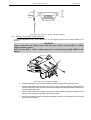
3.3.1
Front Kelping beam to bumper
•
Disconnect Rear Beam from Front Beam by removing connecting axis. Store Rear Beam.
•
Link the motor hoists to the Kelping Beam using front and rear upper axis (fixed beam), and
ensure that these axes are properly locked with the “R” clips supplied.
•
Lift the Kelping Beam and position the bumper below it.
•
Lower the Kelping beam so that the front beam load pin holes are aligned with the bumper load
pin holes (see drawing).
KELPING BEAM TO BUMPER SETUP
•
3.3.2
Connect the Kelping Beam to the bumper with the two axes through the corresponding holes
(see drawing above) and ensure that these are properly locked with the “R” clips.
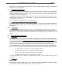
Bumper to first GEO T4805 assembly
4 push-pins (BLGEOT12-35, 12mm diameter x 35 mm length) connect the top GEO T4805 to the
bumper.
IMPORTANT
These 4 push-pins are slightly longer than the ones used to connect GEO T Array
modules (35mm length instead of 30mm).
Never use the GEO T 12mm x 30mm push-pins to connect the top GEO T4805 to the
bumper.
GEO T RIGGING PROCEDURE
Page 17/63
A
BUMPER TO FIRST GEO T4805 ASSEMBLY
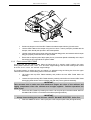
3.3.3
•
Position the bumper on the first GEO T4805 so that the bumper side slot (A) is at the rear.
•
Link the GEO T4805 to the bumper using the four 12mm x 35mm push-pins provided with the
bumper; check that all push-pins are in the locked position.
•
Link the motor hoists to the bumper using front and rear lifting points, and ensure that the bumper
lifting pins properly locked with the “R” clips provided.
•
Ensure that no objects (rolls of tape, spare pins etc.) have been placed accidentally on the top of
the bumper as they might fall when system is lifted.
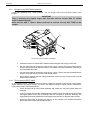
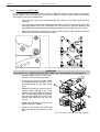
First to second GEO T4805
The linking bar has two oblong holes. When the linking bar is in “tension mode” position, the upper
oblong hole is used for 1.25°, 2.00°, 3.15° and 5.00° angle settings, and the lower oblong hole is used
for 0.125°, 0.20°, 0.315°, 0.5° and 0.8° angle settings.
The angle between a cabinet and the one below it is adjusted using the linking bar from the upper
cabinet and the tension mode setting holes in the lower cabinet.
•
Lift bumper and top GEO T4805 assembly and position the next GEO T4805 below the
assembly.
•
Lower the bumper and top GEO T4805 assembly carefully until the first and second GEO T4805
side rigging plates locate. Use front flanges and side vent ports to guide the assembly.
IMPORTANT
Take extreme care to make sure that hands and fingers are clear of the cabinets and
rigging components when the cabinets are brought together. Careless operation can
cause injury.
•
Fix the two GEO T4805’s by inserting one 12mm x 30 mm push-pin in the hole marked “SAFETY
PIN MUST BE FITTED” on each side of the cabinet (see figure below).
IMPORTANT
Always insert locking pins into the two “SAFETY PIN MUST BE FITTED” holes first.
•
Insert two additional 12mm x 30mm push-pins in the front pivot point holes (see figure below).
Page 18/63
GEO T RIGGING PROCEDURE
“SAFETY PIN MUST BE FITTED“ HOLE
GEO T4805: RIGGING PLATES IN TENSION MODE
•
Lift the bumper and the two first GEO T4805 to a height that allows convenient access to the
linking bars and angle setting holes.
•
The top GEO T4805’s linking bars must be rotated downwards and into the lower GEO T4805’s
side rigging plate (see drawing).
•
One operator must then lift the rear of the bottom GEO T while the angle settings push-pins are
inserted by the second operator on each side of the cabinet.
•
Once the angle setting push-pins are inserted, lower the rear of the lower GEO T: the angle
between the two GEO T4805’s is now correct.
•
Check that all push-pins are locked and that angle settings are identical on both sides.
FIRST GEO T4805 TO SECOND GEO T4805 ASSEMBLY
GEO T RIGGING PROCEDURE
3.3.4
Page 19/63
Subsequent GEO T4805’s
•
Repeat the above section steps, until you have positioned six GEO T4805’s.
•
Fix the speaker cable to the bumper, and connect it to the top GEO T4805.
•
Connect the five speaker links.
•
Check the six cabinets according to the Checklist procedure described in the following section
IMPORTANT – Tension Mode
DO NOT attempt to make any changes to the linking bars while the system is in tension
or while it is being lifted or lowered.
DO NOT attempt to correct any angle mistakes without removing the tension load from
the system. For small arrays, this can be achieved by carefully landing the array and
allowing the cabinets to close together, supported from above by the motor hoist. Take
care during this procedure to keep hands and fingers clear of the rigging system.
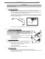
3.3.5
Last GEO T4805 to first GEO T2815
IMPORTANT
Unlike GEO T 4805, GEO T2815 does not have the 0° safety
position.
The linking bar has two oblong holes. When the linking bar is in “tension
mode” position, the upper oblong hole and the upper hole series is used
for 6.3°, 8.00° and 10.0° angle settings.
•
Lift the GEO T4805 array and position the GEO T2815
below the assembly.
•
Using two operators, align the GEO T2815 with the
lowest GEO T4805 so that the pivot point positions
coincide. The profiles of the ‘male’ part of the GEO
T2815 and the ‘female’ part of the GEO T4805 rigging
accessories are designed to align the pivot holes
correctly.
•
Link the bottom GEO T4805 and GEO T2815 by
inserting one 12mm x 30 mm push-pin in the front pivot
point hole on each side of the cabinet (see figure ).
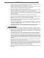
6.3˚
n
ssio ns
pre sitio
Com ng Po
ti
Set
8˚
10˚
15˚
12 GEO T 4805 cluster set in tension mode
12.5˚
Page 20/63
3.3.6
GEO T RIGGING PROCEDURE
•
Lift the bumper and GEO T4805 at a height that allows convenient access to the linking bars and
angle setting holes.
•
Lift the rear of GEO T2815 and insert push-pins into the desired angle setting hole. The centre of
gravity of the GEO T2815 is close to the pivot point and it is very easy to rotate the cabinet to the
desired angle.
•
Once the angle setting push-pins are inserted, release the rear of the GEO T2815: the angle
between the last GEO T4805 and the first GEO T2815 is correct.
•
Check that all push-pins are locked and that angle settings are identical on either side.
First to second GEO T2815
In “tension mode” position, the upper oblong hole and the upper hole series is used for 6.3°, 8.00°,
10.0°, 12.5° and 15° angle settings.
3.3.7
•
Repeat the steps described in 3.3.4 until all GEO T2815 are positioned.
•
Connect the speaker links.
•
Check the bottom cabinets according to the Checklist procedure described later in this manual.
Positioning the cluster
•
If one motor hoist only is used, the bridle chain length must be adjusted for the correct bumper
angle prior to cluster lift.
•
Lift the GEO T array to the height determined in GeoSoft (GeoSoft array height definition is for
the top surface of the topmost cabinet).
•
Adjust the bumper angle as determined in GeoSoft by lowering or lifting rear motor hoist (so that
the front height does not change).
•
Check all GEO T angles with an inclinometer (cumulative error should always be lower than
0.5°).
•
Once the bumper is in definitive position a secondary safety steel must be fitted (this secondary
safety steel should link the bumper to a suitable point in the supporting structure)
IMPORTANT
The requirements for secondary safety systems vary with territories. However, the
secondary safety steel MUST have a SWL equivalent to or greater than the dynamic
weight of the rigging system.
GEO T RIGGING PROCEDURE
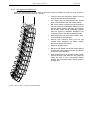
3.3.8
Page 21/63
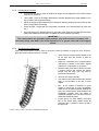
De-rigging and loading out
Taking the system down is just a case of doing the reverse procedure to flying the array. However,
there are some important factors to consider.
10 GEO T 4805 + 2 GEO T 2815 SET IN TENSION MODE
•
Lower the array until the bottom cabinet is just off
the floor and close to horizontal position.
•
Link cables must be disconnected and stowed
away in the recesses in the rear of each cabinet.
•
NB : As the system is lowered it is good practise to
disconnect as many loudspeaker cables as can be
reached without climbing the array. This ensures
that a cable should not be accidentally forgotten
when the system is separated. Damage to the
connector will occur should this mistake be made.
•
While holding the rear of the bottom GEO T 2815,
remove the linking bar push-pins.
•
Remove front push-pins linking the two last
cabinets while supporting the bottom cabinet.
Remove the bottom GEO T2815.
•
Repeat for all GEO T2815.
•
NB: when one cabinet is removed, always balance
front and rear motor hoists so that the next cabinet
is close to horizontal position.
•
While holding the rear of the bottom GEO T4805,
remove the linking bar push-pins and rotate the
linking bar back to the “Compression Setting
Position” at 5° so that the bottom cabinet sits flat in
the flight case.
Page 22/63
3.4
GEO T RIGGING PROCEDURE
•
All other GEO T4805’s should have their linking bars returned to 0.125° position to ensure that
the cabinets stay vertical when landing.
•
Position the flight case underneath the array and carefully lower the array into the flight case,
taking care not to catch any parts in the case.
•
NB: When lowering the system into the flight case, alignment is easier if two operators lift the
flight case onto the bottom of the system as it is lowered. This ensures that the lowest cabinet
does not hit the flight case extrusion if the case is to be mis-aligned.
•
Remove the front and rear push-pins linking the two last cabinets, and carefully lift the array using
both motor hoists until the array is clear.
•
Repeat the procedure for all cabinets.
•
Remove the GEO T bumper. Remember to replace all the pins back in their respective beams.
“Compression Mode Full Kelping Beam” Setup
“Compression mode – Full Kelping Beam” requires the following accessories:
310 mm
[12.20"]
•
GEO T Main Bumper (GEOT-BUMPER)
•
GEO T Kelping Beam (GEOT-KELPBEAM)
•
GEO T Bottom Bumper (GEOT-BTBUMPER)
•
GEO T Kelping Chain (GEOT-BCCH)
GEO T KELPING CHAIN
658 mm
[25.91"]
GEO T MAIN BUMPER
GEO T BOTTOM BUMPER
GEO T FOLDED KELPING BEAM
To be lifted in compression mode, the GEO T bumper requires two motor hoists.
IMPORTANT
Front and rear motor hoists must be rated to support the entire cluster weight.
For arrays of 6 to 18 cabinets, 1 tonne motor hoists are sufficient.
Arrays of 18 cabinets and above should be supported with 2-tons capacity motor hoists.
IMPORTANT
The front motor hoist must be positioned so that there is enough space in front of the
future cluster location to allow the cluster to swing forward without obstruction.
GEO T RIGGING PROCEDURE
3.4.1
Page 23/63
Kelping beam to bumper
•
Link the motor hoists to the Kelping Beam using the front upper axis (fixed beam) and rear upper
axis (articulated beam), and ensure that these axes are properly locked with the “R” clips
supplied.
•
Lift the Kelping Beam and position the bumper below it.
•
Lower the Kelping beam so that the front beam load pin holes are aligned with the bumper load
pin holes (see drawing).
REAR
FRONT
KELPING BEAM TO BUMPER SETUP
•
Connect the Kelping Beam to the bumper with the two axes through the corresponding holes
(see drawing above) and ensure that these are properly locked with the “R” clips.
•
Attach one end of the GEO T Kelping Chain to the Kelping Beam rear lower axis.
•
NB : the GEO T Kelping chain has a clutch assembly 0.5 meter from one end. This is the end
that connects to the bottom GEO T4805, and a small bag is provided for excess chain.
ATTACHING THE GEO T KELPING CHAIN TO THE KELPING BEAM
Page 24/63
3.4.2
GEO T RIGGING PROCEDURE
Bumper to fist GEO T4805 assembly
4 push-pins (BLGEOT12-35, 12mm diameter x 35 mm length) connect the top GEO T4805 to the
bumper.
IMPORTANT
These 4 push-pins are slightly longer than the ones used to connect GEO T’s (35mm
length instead of 30mm).
Never use the GEO T 12mm x 30mm push-pins to connect the top GEO T4805 to the
bumper.
A
FIRST GEO T4805 TO BUMPER ASSEMBLY
3.4.3
•
Position the bumper on the first GEO T4805 so that the bumper side slot (A) is at the rear.
•
Link the GEO T4805 to the bumper using the four 12mm x 35mm push-pins provided with the
bumper; depress the button at the rear of the pin to release the locking mechanism, insert the pin
fully, and release the button.
•
Link the GEO T4805 to the bumper using the four 12mm x 35mm push-pins provided with the
bumper; check that all push-pins are in their locked position.
•
Ensure that no objects have been placed accidentally on the top of the bumper as they may fall
when the system is lifted.
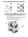
First to second GEOT 4805
In “Compression Mode”, the linking bars must remain inside their respective cabinet side rigging plates.
Angles between one cabinet and the one below are adjusted using the upper cabinet “compression
mode setting” holes (see drawing below).
•
Lift the bumper and top GEO T4805 assembly and position the next GEO T4805 below the
assembly.
•
Lower the bumper and top GEO T4805 assembly carefully until the first and second GEO T4805
side rigging plates locate. Use front flanges and side vent ports to guide the assembly. The
rigging plates have been designed to locate against each other and so align the holes correctly.
•
Fix the two GEO T4805 by inserting one 12mm x 30 mm push-pin in the “SAFETY PIN MUST
BE FITTED” hole on each side (see figure below).
GEO T RIGGING PROCEDURE
“SAFETY PIN MUST BE FITTED“ HOLE
Page 25/63
GEO T4805: RIGGING PLATES IN COMPRESSION MODE
IMPORTANT
The push-pins for “SAFETY PIN MUST BE FITTED” holes must always be inserted first.
•
Insert two additional 12mm x 30mm push-pins in the front holes (see figure below).
•
Lift the bumper and two first GEO T4805 to a height that allows convenient access to the linking
bars and the angle setting holes.
•
Release the linking bar push-pin from its storage position (typically 0.125° when stored in flight
cases), rotate the linking bar within the side rigging plate and position the linking bar oblong hole
in front of the required angle value hole and insert the push-pin.
•
Repeat the angle setting procedure on the opposite side of the cabinet.
•
Check that all push-pins are locked and that angle settings are identical on each side.
FIRST GEO T4805
TO SECOND GEO
T4805 ASSEMBLY
Page 26/63
GEO T RIGGING PROCEDURE
IMPORTANT
DO NOT attempt to make any changes to the linking bars whilst the system is landed or
being lifted or lowered.
•
3.4.4
3.4.5
Subsequent GEO T4805’s
•
Repeat the above section steps, until six GEO T4805 are in place. As the assembly is lifted,
angles between GEO T4805 cabinets will remain at 0° whatever the linking bar positions.
•
NB : In “Compression Mode”, the linking bars are free to be adjusted while the system is clear of
the ground, provided that rear pull-up force is not applied.
•
Once the GEO T4805 assembly is completed, connect the bottom bumper to the last GEO T
4805 with the 12mm x 30mm push-pins inserted in the position marked “Safety Pin Must Be
Inserted” (see drawings below).
•
Check the array according to the Checklist procedure described later in this manual.
Last GEO T4805 to first GEO T2815
IMPORTANT
Unlike GEO T 4805, GEO T2815 does not have the 0° safety
position.
“Compression Mode” only applies to GEO T4805. GEO T2815’s must
always be installed in “Tension Mode”.
3.4.6
•
Follow the instructions given in section 3.3.4 for fitting GEO
T2815 cabinets in tension mode.
•
Check that all push-pins are locked and that angle settings are
identical on each side.
First to second GEO T2815
6.3˚
In “tension mode” position, the upper oblong hole and the upper hole
series is used for 6.3°, 8.00°, 10.0°, 12.5° and 15° angle settings.
•
Repeat the above section steps, until you have positioned the
required number of GEO T2815 cabinets.
•
Connect the speaker links.
•
Check the array according to the Checklist procedure.
n
ssio ns
pre sitio
Com ng Po
ti
Set
8˚
10˚
15˚
12.5˚
GEO T RIGGING PROCEDURE
3.4.7
Page 27/63
Applying compression
•
With the cluster raised 1 meter (~3feet) off the ground, lower the rear motor hoist only. The array
will swing slowly forwards until the centre of gravity lies directly below the front motor hoist.
Continue to lower the rear motor hoist and the rear articulated part of the Kelping Beam will swing
downwards towards the cabinets. Stop the hoist when the rear arm of the Kelping Beam reaches
an elevation of approximately –70 degrees. The angle is approximate and is not critical to the
final angle of the array.
IMPORTANT
When lowering rear motor hoist, the cluster swings forward: ensure there is no obstacle
in front of the cluster within sufficient distance
•
Attach the lower hook of the Kelping Chain Link to the rear of the Bottom Bumper using a 3/4
Shackle.
•
Manually raise the Bottom Bumper until it is approximately parallel with the ground and set the
adjustable clutch in the Kelping Chain Link so that the chain is taught.
•
Make a final check that the Kelping Link Chain is correctly installed and store the surplus chain in
the chain bag supplied. The chain bag should be clipped to the clutch adjuster assembly.
•
The rear motor hoist may now be raised to apply the pull-up force to the bottom of the array.
Notice that, as the rear hoist is raised, the cabinets in the array close together to the angles set
by the linking bar adjustments.
•
When all of the cabinets are closed together the array begins to move as a whole. This is the
indication that the angles have been correctly set. Ensure that the rear arm and the main
member of the Kelping Beam remain at an angle of ~20° with respect to each other, indicating
that the pull-up force will remain constantly applied.
IMPORTANT
DO NOT attempt to make any changes to the linking bars when the rear pull-up force is
applied.
1
2
3
4
Page 28/63
3.4.8
GEO T RIGGING PROCEDURE
Positioning the cluster
•
Adjust the overall height and aiming angle of the array by adjusting the front and rear motor
hoists accordingly. Note that the accuracy of the angle and height of the array are critical and the
appropriate measurement tools are necessary to achieve this (see the appendix for a
recommended list of installation tools).
•
Install a secondary safety steel between the Kelping Beam and a suitable point in the supporting
structure.
IMPORTANT
The requirements for secondary safety systems vary with territories. However, the
secondary safety steel MUST have a SWL equivalent to or greater than that of the rigging
system.
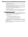
3.4.9
De-rigging and loading out
Taking the system down is just a case of doing
the reverse procedure to flying the array.
However, there are some important factors to
consider.
10 GEO T 4805 + 2 GEO T 2815 set in compression mode
•
Lower the array running the
two
motor
hoists
simultaneously until the
bottom cabinet is just off the
floor.
•
Run the rear motor hoist
down until there is no
tension on the GEO T
kelping chain and no
compression on the system.
•
Disconnect the GEO T
kelping chain from the GEO
T bottom bumper and
remove the bottom bumper
from the array. (You may
have to remove the T2815’s
first)
•
Run the rear motor hoist
back up until the GEO T
kelping beam is level and
the array hangs vertically.
•
Link cables must be
disconnected and stowed
away in the recesses in the
rear of each cabinet.
•
NB : As the system is
lowered it is good practise to
disconnect
as
many
loudspeaker cables as can
be reached without climbing
the array. This ensures that
GEO T RIGGING PROCEDURE
Page 29/63
a cable should not be accidentally forgotten when the system is separated. Damage to the
connector will occur should this mistake be made.
3.5
•
In each group of 3 GEO T4805’s, the linking bar of the lowest GEO T4805 should be returned to
the 5° position in order to sit flat in the flight case.
•
All other GEO T4805’s should have their linking bars returned to 0.125° position to ensure that
the cabinets stay vertical when landing.
•
Position the flight case underneath the array and carefully lower the array into the flight case,
taking care not to catch any parts in the case.
•
NB: When lowering the system into the flight case, alignment is easier if two operators lift the
flight case onto the bottom of the system as it is lowered. This ensures that the lowest cabinet
does not hit the flight case extrusion if the case is mis-aligned.
•
Remove front and rear push pins from the two last cabinets, and carefully lift the array using both
motor hoists until the array is clear. Ensure the array is vertical at all times.
•
Repeat the procedure for all cabinets.
•
Remove the GEO T kelping chain from the GEO T Kelping Beam, the GEO T kelping beam and
the GEO T bumper. Remember to replace all the pins back in their respective beams.
•
Fold the kelping beam and pin it into the closed position for transit.
“Compression Mode – Half Kelping Beam” Setup
“Compression mode – Half Kelping Beam” requires the following accessories:
310 mm
[12.20"]
•
GEO T Main Bumper (GEOT-BUMPER)
•
GEO T Kelping Beam, Front Beam Only (GEOT-KELPBEAM)
•
GEO T Bottom Bumper (GEOT-BTBUMPER)
•
GEO Chain Lever Hoist 1.5 tonne – 9m chain (LEVA1500)
CHAIN LEVER HOIST 1.5 TONNE
658 mm
[25.91"]
GEO T MAIN BUMPER
GEO T BOTTOM BUMPER
GEO T FOLDED KELPING BEAM
Page 30/63
GEO T RIGGING PROCEDURE
To be lifted in “Compression mode – Half Kelping Beam”, the GEO T bumper requires either:
•
one motor hoist and a bridle;
•
or two motor hoists (easier initial angle setting);
In both cases, ensure that the motors are properly rated.
IMPORTANT
Motor hoists must be rated to support the entire cluster weight.
For arrays of 6 to 18 cabinets, 1 tonne motor hoists are sufficient.
Arrays of 18 cabinets and above should be supported with 2-tons capacity motor hoists.
3.5.1
Front Kelping beam to bumper
•
Disconnect Rear Beam from Front Beam by removing connecting axis. Store Rear Beam.
•
Link the motor hoists to the Kelping Beam using front and rear upper axis (fixed beam), and
ensure that these axes are properly locked with the “R” clips supplied.
•
Lift the Kelping Beam and position the bumper below it.
•
Lower the Kelping beam so that the front beam load pin holes are aligned with the bumper load
pin holes (see drawing).
KELPING BEAM TO BUMPER SETUP
•
Connect the Kelping Beam to the bumper with the two axes through the corresponding holes
(see drawing above) and ensure that these are properly locked with the “R” clips.
•
Attach theChain Lever Hoist LEVA1500 chain hook to the Kelping Beam rear lower axis see
drawing below).
•
NB : the Chain Lever Hoist LEVA1500 connects to the bottom GEO T4805, and a small bag is
provided for excess chain.
GEO T RIGGING PROCEDURE
Page 31/63
ATTACHING THE LEVA1500 CHAIN TO THE KELPING BEAM
3.5.2
Bumper to fist GEO T4805 assembly
4 push-pins (BLGEOT12-35, 12mm diameter x 35 mm length) connect the top GEO T4805 to the
bumper.
IMPORTANT
These 4 push-pins are slightly longer than the ones used to connect GEO T’s (35mm
length instead of 30mm).
Never use the GEO T 12mm x 30mm push-pins to connect the top GEO T4805 to the
bumper.
A
FIRST GEO T4805 TO BUMPER ASSEMBLY
•
Position the bumper on the first GEO T4805 so that the bumper side slot (A) is at the rear.
•
Link the GEO T4805 to the bumper using the four 12mm x 35mm push-pins provided with the
bumper; depress the button at the rear of the pin to release the locking mechanism, insert the pin
fully, and release the button.
•
Link the GEO T4805 to the bumper using the four 12mm x 35mm push-pins provided with the
bumper; check that all push-pins are in their locked position.
•
Ensure that no objects have been placed accidentally on the top of the bumper as they may fall
when the system is lifted.
Page 32/63
3.5.3
GEO T RIGGING PROCEDURE
First to second GEOT 4805
In “Compression Mode”, the linking bars must remain inside their respective cabinet side rigging plates.
Angles between one cabinet and the one below are adjusted using the upper cabinet “compression
mode setting” holes (see drawing below).
•
Lift the bumper and top GEO T4805 assembly and position the next GEO T4805 below the
assembly.
•
Lower the bumper and top GEO T4805 assembly carefully until the first and second GEO T4805
side rigging plates locate. Use front flanges and side vent ports to guide the assembly. The
rigging plates have been designed to locate against each other and so align the holes correctly.
•
Fix the two GEO T4805 by inserting one 12mm x 30 mm push-pin in the “SAFETY PIN MUST
BE FITTED” hole on each side (see figure below).
“SAFETY PIN MUST BE FITTED“ HOLE
GEO T4805: RIGGING PLATES IN COMPRESSION MODE
IMPORTANT
The push-pins for “SAFETY PIN MUST BE FITTED” holes must always be inserted first.
•
Insert two additional 12mm x 30mm pushpins in the front holes (see figure below).
•
Lift the bumper and two first GEO T4805
to a height that allows convenient access
to the linking bars and the angle setting
holes.
•
Release the linking bar push-pin from its
storage position (typically 0.125° when
stored in flight cases), rotate the linking bar
within the side rigging plate and position
the linking bar oblong hole in front of the
required angle value hole and insert the
push-pin.
•
Repeat the angle setting procedure on the
opposite side of the cabinet.
•
Check that all push-pins are locked and
that angle settings are identical on each
side.
FIRST GEO T4805 TO SECOND GEO T4805 ASSEMBLY
GEO T RIGGING PROCEDURE
Page 33/63
IMPORTANT
DO NOT attempt to make any changes to the linking bars whilst the system is landed or
being lifted or lowered.
3.5.4
3.5.5
Subsequent GEO T4805’s
•
Repeat the above section steps, until six GEO T4805 are in place. As the assembly is lifted,
angles between GEO T4805 cabinets will remain at 0° whatever the linking bar positions.
•
NB : In “Compression Mode”, the linking bars are free to be adjusted while the system is clear of
the ground, provided that rear pull-up force is not applied.
•
Once the GEO T4805 assembly is completed, connect the bottom bumper to the last GEO T
4805 with the 12mm x 30mm push-pins inserted in the position marked “Safety Pin Must Be
Inserted” (see drawings below).
•
Check the array according to the Checklist procedure described later in this manual.
Last GEO T4805 to first GEO T2815
IMPORTANT
Unlike GEO T 4805, GEO T2815 does not have the 0° safety
position.
“Compression Mode” only applies to GEO T4805. GEO T2815’s must
always be installed in “Tension Mode”.
3.5.6
•
Follow the instructions given in section 3.3.4 for fitting GEO
T2815 cabinets in tension mode.
•
Check that all push-pins are locked and that angle settings are
identical on each side.
First to second GEO T2815
6.3˚
6.3
n
ssio ns
pre sitio
Com ng Po
ti
Set
8˚
10˚
15˚
12.5˚
In “tension mode” position, the upper oblong hole and the upper hole
series is used for 6.3°, 8.00°, 10.0°, 12.5° and 15° angle settings.
3.5.7
•
Repeat the above section steps, until you have positioned the
required number of GEO T2815 cabinets.
•
Connect the speaker links.
•
Check the array according to the Checklist procedure.
Applying compression
•
Raise the cluster 1 meter (~3feet) off the ground keeping bumper horizontal;
•
Manually raise the Bottom Bumper and connect the Chain Lever Hoist hook to the rear of the
Bottom Bumper using a ¾ Shackle.
Page 34/63
GEO T RIGGING PROCEDURE
•
Rotate the fingerwheel clockwise until the chain is taught.
•
Make a final check that the LEVA1500 chain is correctly installed and store the surplus chain in
the chain bag supplied. The chain bag should be clipped to the Chain Lever Hoist.
•
Unse the LEVA1500 lever to apply the pull-up force to the bottom of the array. Notice that, as the
LEVA1500 chain gets shorter, the cabinets in the array close together to the angles set by the
linking bar adjustments.
•
When all of the cabinets are closed together, required force to rotate LEVA1500 lever becomes
much stronger. This is the indication that the angles have been correctly set.
IMPORTANT
DO NOT attempt to force on LEVA1500 lever once you feel it resisting strongly to
rotation; you might damage GEOT flying system by doing so
IMPORTANT
DO NOT attempt to make any changes to the linking bars when the rear pull-up force is
applied.
1
2
3
4
GEO T RIGGING PROCEDURE
3.5.8
Page 35/63
Positioning the cluster
•
If one motor hoist only is used, the bridle chain length must be adjusted for the correct bumper
angle prior to cluster lift.
•
Lift the GEO T array to the height determined in GeoSoft (GeoSoft array height definition is for
the top surface of the topmost cabinet).
•
Adjust the bumper angle as determined in GeoSoft by lowering or lifting rear motor hoist (so that
the front height does not change).
•
Check all GEO T angles with an inclinometer (cumulative error should always be lower than
0.5°).
•
Once the bumper is in definitive position a secondary safety steel must be fitted (this secondary
safety steel should link the bumper to a suitable point in the supporting structure)
IMPORTANT
The requirements for secondary safety systems vary with territories. However, the
secondary safety steel MUST have a SWL equivalent to or greater than that of the rigging
system.
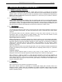
3.5.9
De-rigging and loading out
Taking the system down is just a case of doing the reverse procedure to flying the array. However,
there are some important factors to consider.
•
10 GEO T 4805 + 2 GEO T 2815 SET IN COMPRESSION MODE
•
Lower the array until the bottom cabinet is just
off the floor and the bumper is back to
horizontal.
•
Rotate the LEVA1500 lever counterclockwise
until there is no tension on the GEO T kelping
chain and no compression on the system.
•
Disconnect the LEVA1500 hook from the GEO
T bottom bumper and remove the bottom
bumper from the array. (You may have to
remove the T2815’s first)
•
The array now hangs vertically.
•
Link cables must be disconnected and stowed
away in the recesses in the rear of each
cabinet.
•
NB : As the system is lowered it is good
practise to disconnect as many loudspeaker
cables as can be reached without climbing the
array. This ensures that a cable should not be
accidentally forgotten when the system is
separated. Damage to the connector will occur
should this mistake be made.
•
In each group of 3 GEO T4805’s, the linking
bar of the lowest GEO T4805 should be
returned to the 5° position in order to sit flat in
the flight case.
Page 36/63
3.6
GEO T RIGGING PROCEDURE
•
All other GEO T4805’s should have their linking bars returned to 0.125° position to ensure that
the cabinets stay vertical when landing.
•
Position the flight case underneath the array and carefully lower the array into the flight case,
taking care not to catch any parts in the case.
•
NB: When lowering the system into the flight case, alignment is easier if two operators lift the
flight case onto the bottom of the system as it is lowered. This ensures that the lowest cabinet
does not hit the flight case extrusion if the case is mis-aligned.
•
Remove front and rear push pins from the two last cabinets, and carefully lift the array using both
motor hoists until the array is clear. Ensure the array is vertical at all times.
•
Repeat the procedure for all cabinets.
•
Remove the LEVA1500 chain hook from the GEO T font Kelping Beam, the GEO T kelping
beam and the GEO T bumper. Remember to replace all the pins back in their respective beams.
•
Reassemble front and rear kelping beams, and pin them into the closed position for transit.
Testing and Maintenance of the system
•
General: Geo is a precision piece of equipment and requires regular attention to maintenance in
order to give long and reliable service. NEXO recommends regular testing of loudspeaker rigging
components, preferably using a suitable test rig coupled with a visual inspection.
•
Fasteners: there are several critical points in the Geo T cabinets.
Of primary concern are:
a) The machine screws attaching the rigging system to the cabinet.
b) The screws attaching the rear aluminium section to the cabinet.
c) The screws attaching the directivity flanges to the front of the cabinet.
These fasteners should be regularly checked and tightened as necessary.
•
Cleaning: The exterior of the cabinet and the rigging system can be cleaned with a damp cloth
soaked in mild soapy water. On no account use solvent based cleaners , which may damage the
finish of the cabinet
After cleaning, the rigging system must be treated with a suitable lubricant to prevent rusting. NEXO
recommends the use of Scottoil FS365 which is a water-based lubricant with a mixture of machine
oil, surfactant and anti-rust treatment.
NEXO NX242 DIGITAL CONTROLLER FOR GEO T
4
Page 37/63
NEXO NX242 DIGITAL CONTROLLER FOR GEO T
4.1
NX242 Proprietary Functions
The NX242 is much more than a “generic” Digital Signal Processor. It provides all the standard
functions that you expect from this type of unit, but its real value is the interface between you and your
speaker system. The NX242 includes a number of proprietary functions, developed and refined during
NEXO’s 20 years of loudspeaker development experience, to ensure that your PA delivers maximum
performance and reliability.
4.1.1
Upgradable Firmware
NEXO releases regular firmware updates. Each new release is the result of our ongoing R&D program
combined with user feedback from the field. New firmware releases can include new setups for different
combinations of NEXO full range loudspeakers and subwoofers, improvements to existing setups, and
new software functions. The NX242 is thus evolving with each of those releases, profiting from the
latest discoveries of NEXO’s R&D department as well as the experience of NEXO users.
4.1.2
EQ & Filtering
Subsonic and VHF filtering
Low and high-pass filters are used to filter out frequencies that could possibly degrade the performance
of the TDcontroller and amplifiers. The filters are optimised to work in conjunction with overall system
response.
The high pass filters are also extremely important as they help control excursion at very low
frequencies, which is a major feature for system reliability. This is one of the main reasons to avoid
using setups which are not designed for the cabinet you are using.
Equalising acoustical response
NEXO loudspeakers are acoustically designed for maximum efficiency over their operating bandwidth.
The NX242 provides the correction required to obtain a flat system response. Active rather than passive
attenuation allows the lowering of amplifier voltages for a given output SPL and therefore increases the
maximum SPL achievable with the same amplifier. Active equalisation can also extend a NEXO
loudspeaker’s frequency response, especially at low frequencies where acoustical performance is
limited by cabinet size.
While many DSP processors can provide this type of EQ, none can include the extensive measurement
facilities and listening tests employed by NEXO R&D when adjusting NX242 setups for a particular
loudspeaker.
Crossover section
Crossover between different bands is tuned for every set-up of every cabinet. The crossover is
designed to ensure the best phase alignment possible throughout the crossover overlap region.
Each crossover is “made to measure” in order that each transducer can fit with its neighbour by
achieving a perfect phase alignment. Unconventional filters are used, ranging from 6dB/octave to near
infinite slopes depending of the type of crossover wanted. Time alignment is also performed in an
unconventional way, by using the crossover filter group delays in combination with allpass and/or
frequency dependent delays.
4.1.3
Protection
VCAs and VCEQs
Each channel has its own simulation and protection process.
Each audio channel contains a combination of controlled gain stages (let's call them VCAs as in
analogue circuitry). These VCAs are embedded into complex composite signal chains that adapt
change their basic operation into frequency selective attenuation, similar to an analog voltage controlled
dynamic equaliser (VCEQ).
Page 38/63
NEXO NX242 DIGITAL CONTROLLER FOR GEO T
Each VCEQ and VCA is controlled via synthesis of several signals from the various detection sections.
That synthesis is in fact the envelope of those signals, with an optimised release and attack time for
each VCEQ and VCA (depending on its frequency range and the cabinet selected).
Displacement Control
The Sense input signal is sent to a shaping filter producing a signal whose instantaneous amplitude is
proportional to the voice coil excursion. This signal, after rectification, is compared to a preset threshold
matching the maximum usable value, as determined from laboratory measurements. Any part of the
signal exceeding the threshold is sent to the VCEQ control buffer while the VCEQ acts as an
instantaneous (very short attack time) limiter to prevent displacement from exceeding the maximum
permissible value.
Temperature Control
Each sense signal is fed into a shaping filter (one per transducer), each one producing a signal
proportional to the instantaneous current flowing into the voice coil of the transducer. After rectification,
this signal is integrated with attack and release time constants equivalent to the thermal time constants
of the voice coil and chassis, producing a voltage, which is representative of the instantaneous
temperature of the voice coil.
When this voltage reaches the threshold value corresponding to the driver’s maximum safe operating
temperature, the VCA becomes active to reduce the NX242’s output signal level until the effective
temperature falls below the maximum usable value.
In order to avoid detrimental effects induced by very long release time constants produced by the
temperature detection signal (system output being reduced for an extended period, “pumping” effects,
etc.), the detection signal is modulated by another voltage integrated with faster time constants that
match the subjective perception of sound level. This allows the controller to reduce the effective
operating duration of the temperature limiter and make it sound more natural, while the efficiency of
protection is fully preserved and protection thresholds are kept as high as possible.
Physiologic Dynamic Control
The Physiologic Dynamic Control is intended to avoid unwanted effects produced by long attack time
constants. By anticipating the operation of the temperature limiter, it prevents a high level audio signal
appearing suddenly, then being kept up for long enough to trigger the temperature limiter. Without this,
a rough and delayed gain variation would result that would be quite noticeable and unnatural.
The Physio control voltage acts independently on the VCA with its operation threshold slightly (3 dB)
above that of the temperature limiter and a low compression ratio; its optimised attack time constant
allows it to start operating without any subjectively unpleasant transient effects.
Peak Limiter
The peak limiter primary function is to avoid massive clipping of the amplifier, which can have some
very audible artefacts and in some cases may be damaging to the loudspeakers. Modulation of the
amplifier’s supply voltage rails can create very low frequencies or high-frequency, high level harmonics.
Since these occur after the NX242 in the signal path, they are not filtered by the TDcontroller circuitry.
The threshold of the peak limiter is set by the user to match the amplifier’s clipping point.
The second function of the peak limiter is to avoid huge amounts of power being sent to a driver. Each
driver is protected against overheating and overexcursion, but there could be other failure modes that
cannot be predicted by simulation (especially mechanical damage to the cone). Each driver is specified
for a certain power handling and a factory set peak limiter threshold is tuned to avoid any abuse.
4.2
Cardioid LF and VLF
Cardioid LF and VLF is one of the key advances of the GEO T/CD18 system. This feature is only
achievable with a total control of the DSP chain. Although the basic concept as presented in audio text
books is relatively simple, producing a cardioid pattern from a loudspeaker without a major loss of
efficiency requires advanced DSP processing.
OUTPUT CHANNEL 4
NEXO NX242 DIGITAL CONTROLLER FOR GEO T
Other “loudspeaker management” DSP devices do not provide
the algorithms that the NX242 uses to optimise the cardioid
operation of the GEO T4805, CD18 and CD12.
GEO T2815 low frequency directional behaviour is achieved
by using rear radiating acoustic resistor. These are designed
so that LF dispersion is cardioid. Maximum attenuation is
achieved at 180°, average rear to front attenuation is more
than 12 dB.
EQ
1
Gain2
MUTE
DAC
GEO T4805 LF and CD18 dispersion are digitally set to a
cardioid pattern by adjusting the front and rear 8” loudspeakers
phase and amplitude relationship. Maximum attenuation is
achieved at 180°; average rear to front attenuation is more
than 12 dB.
4.3
4.3.1
GEO T NX242 Setups description
GEO T4805
Hardware configuration
Input can be selected in the MENU 3.2 (L, R
or L+R)
•
Output 1 drives the rear-firing LF 8 inch long
excursion neodymium cone transducers
•
Output 2 drives the front-firing LF/MF 8 inch
long excursion neodymium cone transducers
•
Output 3 drives the HF 3-inch voice coil, 1.4
inch exit neodymium compression driver
•
Output 4 is not used.
VCA
•
Setups
Please refer to the latest version of the NX242 user manual
and firmware (www.NEXO-sa.com).
3
L
1
R
2
R+L
PATCH
DELAY 1
EQ
Analogue part
Digital Audio
Digital servo & protections
4.3.2
GEO T2815
Hardware configuration
PHYSIO 1
Command
PEAK SIMULATION
Command
ChassisTemp.
Voice Coil Temp.
HF TEMPERATURE
Disp.
AMP VOLTAGE AMP GAIN
AD
5
SENSE 1
INPUT L
INPUT R
LF TEMPERATURE
Command
Command
DISPLACEMENT 1
displacement
AMP POWER
Signal
FALLBACK
0
INPUT VU-METER
EQ
SHELVING
0
INPUT VU-METER
AD
SHELVING
EQ
AD
•
Input can be selected in the MENU 3.2 (L, R
or L+R)
•
Output 1 is not used
•
Output 2 drives the LF/MF 8 inch long
excursion neodymium cone transducers
•
Output 3 drives the HF 3-inch voice coil, 1.4
inch exit neodymium compression driver
•
Output 4 is not used.
2
L
1
R
3
R+L
Voice Coil Temp.
Command
ChassisTemp
ATT/REL.
NX241 TDcontroller Partial BLOCK DIAGRAM
Page 39/63
Page 40/63
4.3.3
NEXO NX242 DIGITAL CONTROLLER FOR GEO T
CD18
Hardware configuration
•
Input (L, R or L+R) can be selected in MENU 3.2
•
Output 1 drives the rear-firing 18 inch transducer of the left CD18’s
•
Output 2 drives the front-firing 18 inch transducer of the left CD18’s
•
Output 3 drives the rear-firing 18 inch transducer of the right CD18 ‘s
•
Output 4 drives the front-firing 18 inch transducer of the right CD18 ‘s
Setups
Please refer to the latest versions of the NX242 user manual and firmware (www.NEXO-sa.com).
4.4
Trouble shooting
The NX242 has been designed to be user-friendly. However with highly technical systems such as the
GEO T & CD18, incorrect adjustment of the NX242 can lower the quality & safety of your system. Listed
below are the most common errors encountered by NEXO Technical Support.
4.4.1
Operation of Multiple TDcontrollers
Typically, GEO T/CD18 systems require a minimum of two NX242’s per side (one NX242 for GEO T’s,
another for the CD18’s). Eventually, two or more NX242’s will operate within the same GEO T cluster. It
is mandatory to verify the consistency of the setups and adjustment between processors to avoid the
problems described below.
IMPORTANT
When using multiple NX242’s in a single array, all parameters should be identical and set
to proper values.
4.4.2
Amplifier Power (MENU 2.7)
If the amplifier power (MENU 2.7) is set to a value below the amplifer’s actual power, the peak limiter of
the NX242 will trigger continually, creating audible distortion. Please note that this peak limiter is not set
to act as a compressor on the signal. It is intended to minimize the clipping of the amplifier by operating
slightly after the amplifier’s clipping point.
One way to properly adjust this parameter is to set amplifier power at maximum (5000W) and decrease
the value until the amplifier and TDcontroller clip at the same time.
4.4.3
Amplifier Gain (MENU 2.6)
It is very important to check the gain of each channel. When all amplifier gain switches are set to
identical gain and LF rear and LF/MF front amplifier operate in bridge mono mode, you must remember
to add 6dB to the normal gain on the channels connected to mono bridged amplifiers. If this value is not
set properly the TDcontroller will not be able to protect your system properly. The second line of the
MENU2.6 displays the gain as seen by the NX242 to ease the setting of this parameter.
4.4.4
Gains
If your amplifier gains are not the same on each channel, you will have to adjust the inter-channel gain
in order to compensate for this amplifier gain difference.
4.4.5
Delays
Multiple NX242’s can be used on a single GEO T array. When changing the delay in one NX242
TDcontroller that is part of a multi-controller system, take great care to have exactly the same delay
setting in all NX242 TDcontrollers that receive the same input signal (i.e. all NX242’s that are fed from
the Left output of the mixing console should have the same delay settings). A Tangent Array is very
sensitive to delay differences between sections of the array in the same line. You could experience
coverage problems if all delays applied to a Tangent Array are not equal.
NEXO NX242 DIGITAL CONTROLLER FOR GEO T
Page 41/63
Please refer to the chapter in the NX242 User Manual on setting delay for proper time alignment
between GEO T Series and CD18.
4.4.6
Reversed Cardioid Pattern
Polarity checks are often performed while the system is being set up. Keep in mind that cardioid
speakers may also require a coverage test. If you invert two outputs of the NX242, you could have the
main lobe inverted and firing to the rear. It may be quite hard to detect a reversed cardioid pattern when
it involves one section of a large array.
A good practice is to test the each cabinet in the array with the front speakers only. The system is then
omni-directional. Then turn on the back speaker: you should notice a massive reduction at the back,
and additional level at the front.
This test must be done in addition to the usual polarity test.
4.4.7
Using the wrong NX242 setups for a given cabinet
Each NX242 setup is tailored for a certain NEXO loudspeaker. Using the wrong setup will create safety
and quality problems. Always check that every cabinet in your system is being driven by the correct
NX242 setup.
4.4.8
Connections
To ensure correct electronic behaviour, and to guarantee specifications and EMC performance, a
NX242 must be properly wired. Always use balanced connectors with the shield connected to pin 1 on
both sides. For more wiring recommendations please refer to the application note in the NX242 manual
update.
4.5
Delays & System alignment
4.5.1
Description
The NX242’s factory delay presets are optimised to provide the best possible crossover between the
GEO T and CD18 systems. The reference point for this adjustment is the front of each cabinet. (This
means that the internal delays needed to achieve a correct time alignment are set for cabinets standing
next to each other with both fronts aligned). We recommend that the system is adjusted so that arrivals
from GEOT array and CD18 sub-bass speakers are coincident at a fairly distant listening position.
In the examples below, r1 being the distance from GEO T array to listener position, and r2 being the
distance from CD18 to listener position, the distance difference is then r1–r2 (specified meters or feet).
•
r1 > r2, the delay should be set on the CD18 NX242 TDcontroller.
•
r1 < r2, the delay should be set on the GEO T NX242 TDcontroller
•
To convert the result in time delay (specified in seconds), apply:
•
∆t = (r1-r2)/Cr1 and r2 in meters, C (sound speed) ≈ 343 m/S.
The delay parameter is set in MENU 1.2 (set the units to meters, feet or seconds according to your
preference).
4.5.2
Examples:
Flown CD18s
If the CD18s are flown behind a GEO T Array, delay will have to be adjusted on the GEO T NX242
TDcontrollers according to distance difference r2–r1. (see figure below).
Page 42/63
NEXO NX242 DIGITAL CONTROLLER FOR GEO T
750 mm
[29.53"]
750 mm
[29.53"]
750 mm
[29.53"]
r2
750 mm
[29.53"]
750 mm
[29.53"]
750 mm
[29.53"]
r1
1200 mm
[47.24"]
1200 mm
[47.24"]
1200 mm
[47.24"]
Stacked CD18s
If the CD18s are stacked on the ground, delay will have to be adjusted on the CD18 NX242
TDcontrollers according to the distance difference r1–r2 (see figure below).
r1
750 mm
[29.53"]
750 mm
[29.53"]
r2
750 mm
[29.53"]
750 mm
[29.53"]
750 mm
[29.53"]
750 mm
[29.53"]
1200 mm
[47.24"]
1200 mm
[47.24"]
4.6
Driving the CD18s from the AUX send
1200 mm
[47.24"]
It is quite common to use the AUX send of a mixing desk to drive the Sub section of a PA system. This
gives the mixing engineer more flexibility to set the level of the subbass relative to the main PA, apply
special effects, or to use a different EQ on the Sub. However, it also raises some serious issues for the
performance & safety of the system (mostly time alignment).
4.6.1
What is the phase relation between the AUX and MAIN output of your mixing desk?
At NEXO, when we align systems, we take great care to have an optimum phase alignment from one
octave above to one octave below the crossover frequency point. By doing so, we ensure that both
drivers are working perfectly together and providing the best efficiency possible. It is then up to the user
to adjust the delay on the NX242 to match the physical path difference of the different systems. It is thus
possible to get a well adjusted system, even without measuring instruments.
If you choose to drive the Sub from the AUX, you feed the NX242 with two signals coming from different
sources. If those two sources (MAIN output & AUX send) are not exactly in phase, you are introducing a
delay – without knowing it – into the crossover between your GEO T array and your CD18 subs. Without
the proper measurement tools, you will never be able to tune the system as it should be.
4.6.2
Why it is unlikely the AUX and MAIN have the same phase?
•
Signal paths are likely to be different; any filter modifying the bandwidth and EQ of the
signal is also affecting the phase.
Example: a 24dB/oct high pass filter set at 15Hz is affecting amplitude of the signal by only
0.6dB at 30Hz, but the phase shift is 90°!! At 100Hz we can still measure 25° of phase shift.
NEXO NX242 DIGITAL CONTROLLER FOR GEO T
Page 43/63
•
Should you want to restrict the bandwidth with a low pass filter, you can introduce a phase
difference of up to 180° (completely out of phase) at the cross over point.
•
If the signal is passing though any digital equipment you are adding between 1.4ms and
2.2ms (around 70° phase shift at 100Hz) due solely to the converter delay! The additional
delay due to the processing itself (look ahead compressor, delay…) can be quite important
as well.
If both outputs are not measured in the actual configuration, it is very likely that phase alignment will not
be correct.
4.6.3
Consequences of badly aligned systems
Mis-aligned systems have lower efficiency: i. e. for the same SPL you would be obliged to drive the
system harder, activating the displacement & temperature protection at lower output levels. Both sound
quality and reliability will decrease as the system is stressed. In certain situations you will even need
more speakers to do the same job.
4.6.4
Precautions & Checks
•
Before using the AUX send of your desk, ensure that the outputs are in phase (you can
feed a 1000Hz signal at the input and monitor the MAIN and AUX outputs on a dual trace
oscilloscope).
•
Always apply EQ or processing on both channels at once, so that the phase relationship will
not be altered.
•
Never add additional low pass filtering on the SUB or high pass filtering on the main
system.
•
Inverting polarity on one channel should always result in a massive difference near the
crossover point. If the sound is more or less the same the system is no longer aligned.
Page 44/63
5
GEO T TANGENT ARRAY SYSTEM CHECK LIST
GEO T TANGENT ARRAY SYSTEM CHECK LIST
It is essential to execute all these check steps prior to perform a sound check on the “front end” to the
system. Following this checklist step by step will prevent many troubles and will save time in the end.
5.1
Are the NX242 Digital TDcontrollers properly configured?
IMPORTANT
If you must change any of the parameters listed above, make sure that you use the same
values on all NX242’s.
5.1.1
NX242 Load 2.13 and below
Freq. Band
Gain
Global Gain
Amp Power
Delay
Sense Gain
Array EQ
Headroom
HF
32 dB
0 dB
1350 Watts
0 ms
0 dB
0 dB
5 bars
LF (rear)
32 dB
0 dB
2600 Watts
0 ms
0 dB
0 dB
5 bars
MF/LF (front)
32 dB
0 dB
2600 Watts
0 ms
0 dB
0 dB
5 bars
CD18 Sub
26 dB
0 dB
2000 Watts
0 ms
0 dB
0 dB
5 bars
5.1.2
NX242 Load 2.14 and above
Freq. Band
Gain
Global Gain
Amp Power
Delay
Sense Gain
Array EQ
Headroom
HF
26 dB
0 dB
1350 Watts
0 ms
0 dB
0 dB
5 bars
LF (rear)
32 dB
0 dB
2600 Watts
0 ms
0 dB
0 dB
5 bars
MF/LF (front)
32 dB
0 dB
2600 Watts
0 ms
0 dB
0 dB
5 bars
CD18 Sub
26 dB
0 dB
2000 Watts
0 ms
0 dB
0 dB
5 bars
5.2
Are the amplifiers properly configured?
IMPORTANT NOTE FOR BRIDGE MONO MODE OPERATING AMPLIFIERS
• Bridged mono operating mode adds 6 dB voltage gain.
• Phase relation from amplifier input to output 1(+) and 2(+) has to be checked.
5.2.1
NX242 Load 2.13 and below
Freq. Band
HF
Mode
Stereo
Limiter
None
High Pass
None
LF (rear)
Bridged Mono
26 dB*
None
None
MF/LF (front)
Bridged Mono
26 dB*
None
None
CD18 Sub
Stereo
26 dB
None
None
5.2.2
NX242 Load 2.14 and above
Freq. Band
5.3
Gain Switch
32 dB
Mode
Gain Switch
Limiter
High Pass
HF
Stereo
26 dB
None
LF (rear)
Bridged Mono
26 dB*
None
None
None
MF/LF (front)
Bridged Mono
26 dB*
None
None
CD18 Sub
Stereo
26 dB
None
None
Are the amps and the NX properly connected?
Check that the sense LEDs on the NX242’s used for the full range Tangent Array Modules are
connected properly by applying a signal to the corresponding output and verifying that the correct
Sense LED illuminates.
GEO T TANGENT ARRAY SYSTEM CHECK LIST
5.4
5.5
Page 45/63
Are the speakers properly connected and angled ?
•
Attach the first 6 array modules to the bumper.
•
Before flying, verify that all channels of all modules are functioning properly.
•
Make sure that each module is producing the proper front/rear summation: when listening from
behind the array, switch the front drivers in and out. You should hear a reduction in the LF range
when the both front and rear drivers are on as compared to when the rear drivers only are on.
When listening from the front, you should hear a strong increase in the LF range when
connecting the rear drivers.
•
To check that all front elements have the proper amplitude and phase, you should listen to the six
box cluster at a close distance (<1 meter). You should be able to move from the top to the bottom
of the cluster without hearing any change in the tonal balance.
•
Verify that the angle settings are the same on both sides of each module.
•
Raise the bumper, attach the next 6 modules and repeat the above checks.
•
Make sure that these 6 modules sum properly with the modules above them.
•
When all the modules are flown, check that the aiming angles are the same left and right.
•
Verify that the CD18 is functioning properly: when listening from behind the subs, summing the
front and rear sub drivers lowers the level in comparison with rear driver only.
•
Make sure that multiple CD18s are summing properly: 6 dB gain per doubling of quantity.
Final Pre-Sound Check Check
Play a CD track mono left, and then right : both sides must sound strictly identical. When listening in the
center between two Vertical Tangent Arrays, everything from LF to HF should be located to the
“phantom center” position. If not, repeat the above check sequence to identify the source of the
problem.
Page 46/63
6
TECHNICAL SPECIFICATIONS
TECHNICAL SPECIFICATIONS
6.1
GEO T4805 Vertical Tangent Array Module
6.1.1
System specifications
PRODUCT FEATURES
Components
GEO T4805
Height x Width x Depth
HF: 1 x 3” voice coil, 1.4” throat neodymium 16 Ohm driver on an hyperboloid reflective wavesource.
MF/LF (front-firing): 2 x 8” (20cm) long excursion neodymium hi-flux 16 Ohm drivers in series.
LF (rear-firing): 2 x 8” (20cm) long excursion neodymium hi-flux 16 Ohm drivers in series.
286 x 903 x 627 mm (11 1/4” x 35 1/2” x 24 5/8”) including array assembly system
Shape
5° Trapezoid.
Weight: net
52 kg (114.6 lbs) including array assembly system.
Connectors
1 x AMPHENOL EP6 6 pole socket In; 1 x AMPHENOL AP6 6 pole connector Through.
Construction
Main structure: Baltic birch ply with structured black coating. Rear section: Aluminum with dark grey coating.
Front finish
Injected polyurethane flange, metallic gray coating (structured black on request).
Flying points
Integral flying system.
Intercabinet angle adjustments = 0.125°, 0.2°, 0.315°, 0.5°, 0.8°; 1.25°, 2.0°, 3.15°, 5° (logarithmic steps)
SYSTEM SPECIFICATIONS
Frequency response [a]
GEO T4805 with NX242 TDcontroller
67 Hz – 19 kHz ± 3 dB
Usable range @-6dB [a]
60 Hz – 20 kHz
Sensitivity 1W @ 1m [b]
109 dB SPL nominal (107 dB SPL wideband)
Peak SPL @ 1m [b]
Configuration dependent [d].
Dispersion [c]
Vertical plane: Configuration dependent [d].
Horizontal plane: 90°.
Low Frequency: cardioid
LF-MF: 250 Hz active; MF-HF: 1.3 kHz active
Crossover frequencies
Nominal impedance
HF: 16 Ohm; LF/MF front: 32 Ohm; LF rear: 32 Ohm
Recommended amplifiers
HF: 2700 Watts into ~3 Ohm (6 cabinets parallel per amp channel).
MF/LF front: 5200 Watts into ~6 Ohm (6 cabinets parallel per bridged mono amp).
LF rear section: 5200 Watts into ~6 Ohm (6 cabinets parallel per bridged mono amp).
SYSTEM OPERATION
Electronic controller
Array design
The NX242 Digital TDcontroller presets are precisely matched to the GEO T Series cabinets and include sophisticated
protection systems as well as advanced cardioid directivity DSP algorithms. Using GEO T Series cabinets without a
properly connected NX242 will result in poor sound quality and can damage components.
Arrays of less than 6 x GEO T4805 will provide poor dispersion control and are neither recommended nor supported.
Sub-bass
CD18 directional sub extends system low frequency response down to 25 Hz
Speaker cables
HF: wired 5(-) / 6(+).
MF/LF front section: wired 3(-) / 4(+).
LF rear section: wired 1(-) / 2(+).
Please refer to the GEO user manual before any operation.
Rigging System
As part of a policy of continual improvement, NEXO reserves the right to change specifications without notice.
[a]
Response curves and data: anechoic far field above 200 Hz, half-space anechoic below 200 Hz.
[b]
Sensitivity & peak SPL: will depend on spectral distribution. Measured with band limited pink noise.
Refers to the specified +/- 3 dB range. Data are for speaker + processor + recommended amplifier combinations.
[c]
Directivity curves and data: 1/3 octave smoothed frequency response, normalized to on-axis response. Data obtained by computer processing of off-axis
response curves.
[d]
Please refer to the GEO T user Manual.
Usable range data: frequency response capability with TD crossover slopes removed.
TECHNICAL SPECIFICATIONS
6.1.2
Page 47/63
GEO T4805 Dimensions
903 mm
[35.55"]
286 mm
[11.26"]
250 mm
[9.84"]
750 mm
[29.53"]
627 mm
[24.68"]
6.1.3
Architects’ & Engineers’ Specifications
The 3-way full range tangent array module shall have four 8 inch 16 Ohm long excursion neodymium hiflux cone transducers in series (two front-firing, two rear-firing), and a 1.4 inch exit 16 Ohm neodymium
compression driver on a hyperboloid reflective wavesource. Coverage shall be configuration-dependent
in the vertical plane and 90° in the horizontal plane. The system shall have a nominal sensitivity of
109dB (107dB wideband). When driven by a NEXO NX242 Digital TDcontroller properly connected to
amplification capable of delivering 5200 Watts into a 5 Ohm load (6 cabinets per channel in parallel),
the system shall produce 138dB peak SPL at 1 meter (for a single enclosure: configuration-dependent
when arrayed) with a frequency response of 67 Hz to 19 kHz ±3 dB (60 Hz to 20 kHz ±6 dB). The
system shall have an active crossover with crossover points of 250 Hz and 1.3 kHz. Low frequency
directional control shall be achieved with DSP algorithms. Electrical connections shall be made via one
6 pole AMPHENOL EP6 socket and one 6 pole AMPHENOL EP6 plug. The system shall have a tuned
ported 5° trapezoidal enclosure constructed of 18 ply Baltic birch (midsection) and aluminium (rear
driver compartment), finished in structured black coating and having exterior dimensions no greater
than 286mm H x 903mm W x 627mm D (11 1/4 in H x 35 1/2 in W x 24 5/8 in D): the system shall weigh
52kg (114.6 lbs). Exterior hardware shall include an integral array assembly system with logarithmic
steps and 0.01° precision: interior components shall be protected by an injection-molded polyurethane
Configurable Directivity Device flange. The full range system shall be the NEXO GEO T4805 with a
NEXO NX242 Digital TDcontroller. Other integrated loudspeaker/controller systems shall be acceptable,
provided submitted results of testing by an independent laboratory verify that the above specifications
are equalled or exceeded.
.
Page 48/63
6.2
TECHNICAL SPECIFICATIONS
GEO T2815 Vertical Tangent Array Module
6.2.1
System specifications
PRODUCT FEATURES
Components
GEO T2815
Height x Width x Depth
HF: 1 x 3” voice coil, 1.4” throat neodymium 16 Ohm driver on an hyperboloid reflective wavesource.
MF/LF: 2 x 8” (20cm) long excursion neodymium hi-flux 16 Ohm drivers in series.
Rear Passive Acoustic Resistor
249 x 903 x 537 mm (9 13/16” x 35 1/2” x 21 1/8”) including array assembly system
Shape
15° Trapezoid.
Weight: net
29 kg (63.9 lbs) including array assembly system.
Connectors
1 x AMPHENOL EP6 6 pole socket In; 1 x AMPHENOL AP6 6 pole connector Through.
Construction
Main structure: Baltic birch ply with structured black coating. Rear section: Aluminum with dark grey coating.
Front finish
Injected polyurethane flange, metallic gray coating (structured black on request).
Flying points
Integral flying system.
Intercabinet angle adjustments = 6.30°, 8.00°, 10.0°, 12.5°, 15° (logarithmic steps)
SYSTEM SPECIFICATIONS
Frequency response [a]
GEO T2815 with NX242 TDcontroller
85 Hz – 19 kHz ± 3 dB
Usable range @-6dB [a]
77 Hz – 20 kHz
Sensitivity 1W @ 1m [b]
107 dB SPL nominal (105 dB SPL wideband)
Peak SPL @ 1m [b]
Configuration dependent [d].
Dispersion [c]
Vertical plane: Configuration dependent [d].
Horizontal plane: 120°.
Low Frequency: cardioid
LF/MF-HF: 1.3 kHz active
Crossover frequencies
Nominal impedance
HF: 16 Ohm; LF/MF: 32 Ohm
Recommended amplifiers
HF: 2700 Watts into ~3 Ohm (6 cabinets parallel per amp channel).
MF/LF: 5200 Watts into ~6 Ohm (6 cabinets parallel per bridged mono amp).
SYSTEM OPERATION
Electronic controller
Array design
The NX242 Digital TDcontroller presets are precisely matched to the GEO T Series cabinets and include sophisticated
protection systems as well as advanced cardioid directivity DSP algorithms. Using GEO T Series cabinets without a
properly connected NX242 will result in poor sound quality and can damage components.
Arrays of less than 4 x GEO T2815 will provide poor dispersion control and are neither recommended nor supported.
Sub-bass
CD18 directional sub extends system low frequency response down to 25 Hz
Speaker cables
HF: wired 5(-) / 6(+).
MF/LF: wired 3(-) / 4(+).
1(-) / 2(+) not connected (through).
Please refer to the GEO user manual before any operation.
Rigging System
As part of a policy of continual improvement, NEXO reserves the right to change specifications without notice.
[a]
Response curves and data: anechoic far field above 200 Hz, half-space anechoic below 200 Hz.
[b]
Sensitivity & peak SPL: will depend on spectral distribution. Measured with band limited pink noise.
Refers to the specified +/- 3 dB range. Data are for speaker + processor + recommended amplifier combinations.
[c]
Directivity curves and data: 1/3 octave smoothed frequency response, normalized to on-axis response. Data obtained by computer processing of off-axis
response curves.
[d]
Please refer to the GEO T user Manual.
Usable range data: frequency response capability with TD crossover slopes removed.
TECHNICAL SPECIFICATIONS
6.2.2
Page 49/63
GEO T2815 Dimensions
903 mm
[35.55"]
249 mm
[9.80"]
213 mm
[8.39"]
750 mm
[29.53"]
537 mm
[21.14"]
6.2.3
Architects’ & Engineers’ Specifications
The 2-way full range tangent array module shall have two 8 inch 16 Ohm long excursion neodymium hiflux cone transducers in series, two rear passive acoustic resistors and a 1.4 inch exit 16 Ohm
neodymium compression driver on a hyperboloid reflective wavesource. Coverage shall be
configuration-dependent in the vertical plane and 120° in the horizontal plane. The system shall have a
nominal sensitivity of 107dB (105dB wideband). When driven by a NEXO NX242 Digital TDcontroller
properly connected to amplification capable of delivering 5200 Watts into a 5 Ohm load (6 cabinets per
channel in parallel), the system shall produce 135dB peak SPL (for a single enclosure: configurationdependent when arrayed) with a frequency response of 85 Hz to 19 kHz ±3 dB (77 Hz to 20 kHz ±6 dB).
The system shall have an active crossover with DSP algorithms and a crossover point of 1.3 kHz.
Electrical connections shall be made via one 6 pole AMPHENOL EP6 socket and one 6 pole
AMPHENOL EP6 plug. The system shall have a 15° trapezoidal enclosure constructed of 18 ply Baltic
birch (midsection) and aluminium, finished in structured black coating and having exterior dimensions
no greater than 249mm H x 903mm W x 537mm D (9 13/16 in H x 35 1/2 in W x 21 1/8 in D): the
system shall weigh 29kg (63.9 lbs). Exterior hardware shall include an integral array assembly system
with logarithmic steps and 0.01° precision: interior components shall be protected by an injectionmolded polyurethane Configurable Directivity Device flange. The full range system shall be the NEXO
GEO T2815 with a NEXO NX242 Digital TDcontroller. Other integrated loudspeaker/controller systems
shall be acceptable, provided submitted results of testing by an independent laboratory verify that the
above specifications are equalled or exceeded.
Page 50/63
6.3
TECHNICAL SPECIFICATIONS
CD18 Directional Sub-Bass
6.3.1
System specifications
PRODUCT FEATURES
CD18
Components
2 x 18” (46cm) long excursion neodymium 8 Ohm drivers
Height x Width x Depth
750 x 1200 x 750 mm (29 1/2” x 47 1/4” x 29 1/2”)
Shape
Rectangular
Weight: Net
116 kg (256 lbs)
Connectors
2 x NL4MP SPEAKON 4 pole (In & Through)
Construction
Baltic birch ply finish with structured black coating. Dark grey carpet finish also available.
Flying points
Integral flying system.
SYSTEM SPECIFICATIONS
CD18 with NX242 TDcontroller
Frequency Response @-3dB [a]
32 Hz – 80 Hz
Usable Range @-6dB [a]
29 Hz – 180 Hz
Sensitivity 1W @ 1m [b]
105 dB SPL Nominal
Peak SPL @ 1m [b]
142-145 dB Peak
Dispersion [c]
Cardioid pattern over the entire useable bandwidth (two channels of the NX242 are used for the process).
Directivity Index [c]
Q = 4.3 & DI = 5.3 dB over the entire useable bandwidth.
Crossover Frequency
80 Hz active through NX242 Digital TDcontroller.
Nominal Impedance
2 x 8 Ohm
Recommended Amplifiers
2 amplifier channels are required for directional operation, each rated at 1000 to 2000 Watts into 8 Ohm per
channel.
SYSTEM OPERATION
Electronic Controller
Speaker Cables
Rigging System [d]
The NX242 Digital TDcontroller presets are precisely matched to the CD18 and include sophisticated protection
systems. Using the CD18 subbass without a properly connected NX242 Digital TDcontroller will result in poor
sound quality and can damage components.
The front loudspeaker of the CD18 is wired 2+ & 2- while the rear loudspeaker is wired 1- & 1+. The CD18 must
use separate cables from the main system.
Please refer to the user manual before any operation.
As part of a policy of continual improvement, NEXO reserves the right to change specifications without notice.
[a]
Response curves and data: anechoic far field above 400 Hz, half-space anechoic below 400 Hz.
Usable range data: frequency response capability with TD crossover slopes removed.
[b]
Sensitivity & peak SPL: will depend on spectral distribution. Measured with band limited pink noise.
Refers to the specified +/- 3 dB range. Data are for speaker + processor + recommended amplifier combinations.
[c]
Directivity curves and data: 1/3 octave smoothed frequency response, normalized to on-axis response. Data obtained by computer processing of off-axis
response curves.
[d]
Please refer to the user manual.
TECHNICAL SPECIFICATIONS
6.3.2
Page 51/63
CD18 dimensions
750 mm
[29.53"]
750 mm
[29.53"]
750 mm
[29.53"]
750 mm
[29.53"]
1200 mm
[47.24"]
1200 mm
[47.24"]
6.3.3
Architects’ & Engineers’ Specifications
The subbass loudspeaker system shall have two 18 inch long excursion 8 Ohm cone transducers. Its
horizontal and vertical dispersion shall be 120° (cardioid pattern). The system shall have a Q of 4.3
(cardioid mode) over is entire operating frequency range. The system shall have a nominal sensitivity of
105dB/1W/1m. When driven by a NEXO NX242 Digital TDcontroller properly connected to amplification
capable of delivering 1000 to 2000 Watts into a 2x 8 Ohm load (two channels required for directional
VLF), the system shall produce 142 to 145dB peak SPL with a frequency response of 32 Hz to 80 Hz ±3
dB (29 Hz to 180 Hz ±6 dB). The system shall have an active crossover with DSP algorithms for
directional control of sub bass with a crossover point of 80 Hz. Electrical connections shall be made via
two 4 pole NL4MP SPEAKON connectors. The system shall have a tuned dual-ported rectangular
enclosure constructed of 18 ply Baltic birch with low speed port geometry, finished in structured black
coating or dark grey carpeting and having exterior dimensions no greater than 750mm H x 1200mm W x
750mm D (29 1/2 in H x 47 1/4 in W x 29 1/2 in D): the system shall weigh 116kg (256 lbs). Exterior
hardware shall include four front-mounted flytracks, four rear-mounted flytracks and four handles. The
subbass system shall be the NEXO GEO CD18 with a NEXO NX242 Digital TDcontroller. Other
integrated loudspeaker/controller systems shall be acceptable, provided submitted results of testing by
an independent laboratory verify that the above specifications are equalled or exceeded.
Page 52/63
TECHNICAL SPECIFICATIONS
6.4 GEO T Rigging system
6.4.1
GEO T Bumper
911 mm
[35.87"]
310 mm
[12.20"]
839 mm
[33.03"]
658 mm
[25.91"]
WEIGHT : 45 KG / 99.2 LBS
6.4.2
GEO T Kelping Beam
1850 mm
1247 mm
[72.83"]
[49.09"]
1075 mm
[42.32"]
850 mm
[33.46"]
418 mm
405 mm
[16.46"]
[15.94"]
WEIGHT : 53 KG / 116.8 LBS
TECHNICAL SPECIFICATIONS
Page 53/63
836.5 mm
[32.93"]
6.4.3
GEO T Bottom Bumper
35 mm
[1.38"]
836.5 mm
[32.93"]
35 mm
[1.38"]
474 mm
[18.66"]
WEIGHT: 9.5 KG / 20.9 LBS
474 mm
[18.66"]
Page 54/63
6.5
6.5.1
TECHNICAL SPECIFICATIONS
NX242 TDcontroller
Specifications
SPECIFICATIONS
NX242 Digital TDcontroller
Output Level
+28 dBu Max. into 600 Ohm load
Dynamic Range
Channels 1 & 2 = 99 dBu
Channel 3 & 4 = typical 107 dBu. (Flat without gain scaling: 101dBu)
THD + Noise
< 0.02% flat setup (max0.04% for Output 27.5dBu)
Latency time
1.4ms on a flat setup
Power Supply
115/230 Volts 50/60 Hz (operating range 90-125V & 180-264V)
FEATURES
Audio Inputs
2 Audio Inputs 24 bit converters
Electronically Balanced, 36 k Ohm.
2 XLR-3F Connectors.
Sense Inputs
4 Amplifier Sense Inputs (LF mono, MF/HF L&R)
Floating 150 kΩ. 18 bit converters
8 Pole Removable Strip Terminal.
Audio Outputs
4 Audio Outputs. 24 bit converters
Electronically balanced, 50 Ohm
4 XLR-3M connectors
Processing
24 bit data with 48-bit accumulator. 100MIPS
Optional Expansion Board 300MIPS
Front Panel
Menu A and Menu B buttons
16 characters by 2 lines display
Select Wheel & Enter button ()
IN Clip – DSP Clip red LED’s
Speaker Protection yellow LED for each channel
Individual Mute/Solo buttons and red LED for each channel
Amp. Sense & Peak (green & red) LED’s for each channel
FLASH EPROM
Rear Panel
Software updates/upgrades, new system setups, available on www.nexo-sa.com
90-240 V
Fuse holder
RS232 connector for serial com
Empty slot for extension card (communication & processing power)
Dimensions & Weight
1U 19" Rack - 230 mm (9") Depth.
4 kg
6.5.2
Front and Rear Panel view
8
SENSE 4
7
SENSE 3
6
SENSE 2
5
SENSE 1
INPUT L
AD
AD
AD
AD
0
AMP POWER
Signal
EQ
EQ
AMP POWER
Signal
AMP POWER
Signal
Signal
AMP POWER
AMP VOLTAGE AMP GAIN
FALLBACK
AMP VOLTAGE AMP GAIN
FALLBACK
AMP VOLTAGE AMP GAIN
FALLBACK
AMP VOLTAGE AMP GAIN
FALLBACK
INPUT VU-METER
AD
INPUT VU-METER
0
ChassisTemp.
Voice Coil Temp.
Command
displacement
ChassisTemp.
Voice Coil Temp.
Command
ChassisTemp.
Voice Coil Temp.
Command
PEAK SIMULATION 4
Command
HF TEMPERATURE 4
Command
LF TEMPERATURE 4
Disp.
displacement
Command
DISPLACEMENT 4
PEAK SIMULATION 3
Command
HF TEMPERATURE 3
Command
LF TEMPERATURE 3
Disp.
displacement
Command
DISPLACEMENT 3
PEAK SIMULATION 2
Command
HF TEMPERATURE 2
Command
LF TEMPERATURE 2
ChassisTemp.
Voice Coil Temp.
Command
displacement
Command
DISPLACEMENT 2
PEAK SIMULATION
Command
HF TEMPERATURE
Command
LF TEMPERATURE
Disp.
1
R
PHYSIO 2
Voice Coil Temp.
Command
ChassisTemp
PHYSIO 1
Voice Coil Temp.
Command
ChassisTemp
PHYSIO 4
Voice Coil Temp.
Command
ChassisTemp
PHYSIO 3
Voice Coil Temp.
Command
ChassisTemp
2
L
3
R+L
Command
DISPLACEMENT 1
Disp.
SHELVING
SHELVING
ATT/REL.3
ATT/REL.2
ATT/REL.1
ATT/REL.
16
L3
15
R+L 3
14
R3
13
L2
12
R+L 2
11
R2
10
L1
9
R+L 1
4
R1
3
L
2
R+L
1
R
PATCH 4
PATCH 3
PATCH 2
DELAY 3
DELAY 2
DELAY 4
PATCH
DELAY 1
EQ
EQ
EQ
EQ
VCA
VCA
VCA
VCA
Analogue part
Digital Audio
Digital servo & protections
NX241 TDcontroller BLOCK DIAGRAM
EQ
EQ
EQ
EQ
1
Gain18
Gain13
1
Gain8
1
1
MUTE
MUTE
MUTE
MUTE
Gain2
DAC
DAC
DAC
DAC
OUTPUT CHANNEL 1
OUTPUT CHANNEL 2
OUTPUT CHANNEL 3
OUTPUT CHANNEL 4
6.5.3
INPUT R
AD
TECHNICAL SPECIFICATIONS
Page 55/63
Block Diagram
Page 56/63
7
7.1
CONNECTION DIAGRAMS
CONNECTION DIAGRAMS
GEO T4805 / T2815 to amplifiers and NX242
CONNECTION DIAGRAMS
7.2
CD18 to amplifiers and NX242
Page 57/63
Page 58/63
8
8.1
GEO T SERIES PARTS & ACCESSORIES LIST
GEO T SERIES PARTS & ACCESSORIES LIST
Array Modules & Control Electronics List
MODEL
DRAWING
GEO T4805
8.2
DESCRIPTION
GEO 4x 8” Neodymium 5° Module (+6x BLGEOT
12-30)
GEO T2815
GEO 2x 8” Neodymium 15° Module (+4x BLGEOT
12-30)
CD18-C
CD18 2x 18" Carpeted Cardioid
CD18-P
CD18 2x 18" Painted Cardioid
ANX 242
Digital TDcontroller for PS, Alpha and Geo series
Accessories List
MODEL
GEOT-BUMPER
GEOT-BCCH
DRAWING
DESCRIPTION
Main Geo T Bumper (4x BLGEOT 12-35 included)
Compression Mode Kelping Chain
GEOTBTBUMPER
Geo T Bottom Bumper
GEOTKELPBEAM
Geo T Kelping Beam
GEO T SERIES PARTS & ACCESSORIES LIST
MODEL
DRAWING
DESCRIPTION
LEVA1500
Chain Lever Hoist 1.5 tonne (9 meters chain)
GEOT-RAINCO
Geo T Waterproof Back Cover (up to 6 cabinets)
GEOTBPRAINCO
Geo T Bumper Waterproof Back Cover
CD18-WB
BLGEOT12-30
BLGEOT12-35
GEOT-CABLE
GEOT-613F
GEOT-612M
Page 59/63
CD 18 WheelBoard
GEO T 12mm x 30mm Quick Release Pin
GEO T Bumper 12mm x 35mm Quick Release Pin
1m Linking Cable For Geo T4805/T2815
EP6 Female Connector
AP6 Male Connector
Page 60/63
9
RECOMMENDED INSTALLATION TOOLS AND EQUIPMENT
RECOMMENDED INSTALLATION TOOLS AND EQUIPMENT
•
Tape measure – should be 30m/100ft in length and be of durable fibre material. Have one per
array available to speed up the installation process.
•
Laser inclinometer – For measuring vertical and horizontal angles in the venue. An ideal product
is the Calpac ‘Laser projecting a dot’ version which costs approximately €60.
•
Spirit level – used to ascertain the trueness of the surface from which the angle measurements
originate.
•
Rangefinder measuring device – either a Disto type laser measure or an optical laser rangefinder
can be used. Devices such as the Bushnell ‘Yardage Pro’ sports rangefinders provide sufficiently
accuracy and are easy to use. They have the additional advantage of working very well in bright
sunlight.
•
Electronic calculator with trigonometric functions to calculate the height from ground level to
points in the room. The formula to calculate height of a point from measured angle and distance
is:
•
Height of point = Sin(vertical angle in degrees) x distance to point
•
NB: Take care when using spreadsheets as they calculate using radians by default. To convert
degrees to radians use the formula:
•
Angle (in radians)=3.142 x Angle (in degrees)/180
•
Computer – Laptop or Desktop PC running Windows 95/98/2000 or XP with the current version
of NEXO GeoSoft installed. It is not possible to configure a Geo tangent array properly without
using GeoSoft. Note that, when GeoSoft designs are prepared prior to arrival at the venue, it is
often necessary to modify or update the design to accommodate special circumstances. A PC is
absolutely essential to make such changes.
•
Digital remote inclinometer – with a remote sensor in the bumper and a meter unit at ground level
to ensure precise installation of the cluster. A typical unit for this purpose is the Schaevitz
Anglestar which typically costs around €350 for a sensor and meter unit pair. At greater cost but
with very high precision is the NEXO GeoSight system that predicts the stationary angle of the
array, even while it is swinging, and has a green laser mounted coincident to and parallel with the
axis of the topmost cabinet.
•
Audio Analysis Software – recommended but not absolutely essential, programs such as SIA
Smaart Pro or Spectrafoo enable rapid and detailed analysis of the installation. Consider taking a
training course in using one of these tools if you are not already competent with them – it will pay
dividends in increased performance of the system.
USER NOTES
10 USER NOTES
Page 61/63
France
Nexo S.A.
154 allée des Erables
ZAC des PARIS NORD II B.P.
50107
F-95950 Roissy CDG Cedex
Tel: +33 1 48 63 19 14
Fax: +33 1 48 63 24 61
E-mail: [email protected]
www.nexo-sa.com