1
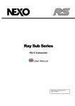
GEO S Series
S805 5° Tangent Array Module
S830 30° Tangent Array Module
CD12 HyperCardoid Subbass
User Manual
P.2
INTRODUCTION
GEO is new technology
The 3 year GEO R&D Project has generated the following patent applications:
•
The GEO Hyperboloid Reflective Wavesource™ works on a different principle from the
coercive megaphone-variant horns you know and love/hate. If you apply “tried and true”
methods to this entirely different species of waveguide, the results are likely to be very
different from what you expect.
•
The Configurable Directivity Device. A waveguide that allows the operator to alter its
behaviour in the field? Yes. Another unprecedented development that’s easy to use – once
you know how and when.
•
The Directivity Phase Device needs no operator input to work properly, but it’s always nice
to know…
GEO is not hard to use when you understand how…
The R&D behind GEO is revolutionary, but it is grounded in years of practical experience with the problems of
delivering high quality sound to large audiences at professional SPL levels. GEO includes a simple yet
powerful and highly predictive design tool – GEOSoft2. The array assembly system is keyed to the design
software and will easily enable you to deploy your design with precision to 0.01°. The NX242 includes presets
that have been tested and measured by NEXO R&D. They cover virtually any GEO tangent array
configuration, horizontal or vertical, with or without the CD12 HyperCardioid Subbass.
GEO is a high precision system
The GEO Wavesource controls acoustic energy more precisely than previous generations of coercive
waveguides based on the megaphone. This precision makes the GEO system more capable than previous
array elements. It also makes GEO less forgiving of mistakes in design and deployment. While megaphonevariant horns never combine into a coherent array, they can deliver acceptable results even if the design and
deployment of the system is less than optimal. This is not the case with GEO.
GEO is a tangent array, not a “line array”
GEO Technology is equally effective in designing and deploying tangent horizontal arrays or curved vertical
arrays. For best results in a specific application you need to know how multi-speaker arrays interact with
audience geometry, along with the benefits and drawbacks of curved vertical arrays and horizontal arrays.
Curved vertical tangent arrays require different design techniques
For the past 20 years, sound reinforcement professionals have worked with horizontal arrays that use
megaphone-variant horns to deliver “[more or less] equal power to equal angles.” Curved vertical arrays are
designed to deliver “equal power to equal areas.” When conventional coercive horns are used in the array
elements, their lack of precision masks errors in the design of the array and in the aiming of the individual
cabinets. The highly precise GEO wavesource responds accurately, consistently and predictably to the design
and deployment of a curved vertical tangent array. This is why the GEO rigging system is designed to control
angular splay to 0.01° accuracy.
GEO curved vertical tangent arrays require different operational techniques
Over the years, system designers and operators have developed a number of signal processing techniques to
disguise and partly overcome the limitations of coercive megaphone waveguides. “Frequency shading,”
“amplitude shading,” “system tuning,” all of these are tools of the advanced sound system operator. NONE OF
THESE TECHNIQUES ARE APPLICABLE TO GEO TANGENT ARRAYS. Instead of enhancing the array’s
performance they will severely degrade it.
Take a little time to learn how to get great results with GEO Technology. It’s an investment that will pay off in
more satisfied clients, more efficient operating procedures and more recognition for your skill as a sound
system designer and operator
GEO S SERIES USER MANUAL V1.04
Date: 22/12/2005
INTRODUCTION
P.3
TABLE OF CONTENTS
INTRODUCTION...........................................................................................................................................................................4
GENERAL SET-UP INSTRUCTIONS...............................................................................................................................................5
Speaker Wiring ....................................................................................................................................................................5
Amplifier Selection ...............................................................................................................................................................6
NX242 DIGITAL TDCONTROLLER SETTINGS...............................................................................................................................8
GEO Vertical Arrays ............................................................................................................................................................8
GEO Horizontal Tangent Arrays.........................................................................................................................................9
Speaker Quantity.................................................................................................................................................................9
Delays & System Alignment............................................................................................................................................. 10
Initial Set-up Precautions ................................................................................................................................................. 10
DEPLOYING GEO TANGENT ARRAYS ...................................................................................................................................... 11
Vertical vs. Horizontal....................................................................................................................................................... 11
CD12 HyperCardioid Subbass ........................................................................................................................................ 11
GEOSOFT2............................................................................................................................................................................ 12
USING THE CONFIGURABLE DIRECTIVITY DEVICE .................................................................................................................... 13
Installing & removing GEO’s Configurable Directivity flanges........................................................................................ 13
When & where to use Configurable Directivity flanges .................................................................................................. 14
GEO APPLICATION GUIDELINES ............................................................................................................................................. 15
GEO TANGENT ARRAY RIGGING SYSTEM............................................................................................................................... 16
SAFETY FIRST ................................................................................................................................................................ 16
GEO Loudspeakers.......................................................................................................................................................... 18
Angle-setting bar............................................................................................................................................................... 19
Assembling a curved vertical GEO array ........................................................................................................................ 19
CD12 BUMPER................................................................................................................................................................ 21
Combination GEO/CD12 bumper.................................................................................................................................... 22
Assembling Horizontal GEO Arrays ................................................................................................................................ 23
Ground stacking Geo Array ............................................................................................................................................. 23
Dimensions & Weights ..................................................................................................................................................... 24
TECHNICAL SPECIFICATIONS ................................................................................................................................................... 25
GEO S805......................................................................................................................................................................... 25
GEO S830......................................................................................................................................................................... 27
GEO CD12........................................................................................................................................................................ 29
USER’S NOTES ........................................................................................................................................................................ 31
P.4
INTRODUCTION
INTRODUCTION
Thank you for selecting NEXO GEO S Series products. This manual is intended to provide you with
necessary and useful information about your GEO System, which includes the following products:
•
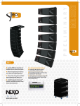
S805 5° Tangent Array Module. 8” (20cm) Neodymium Hi-flux 16 Ohm LF Driver and 1”
Throat Neodymium HF Driver on a 5° Hyperboloid Reflective Wavesource. Your main
building block for curved vertical tangent arrays; integral precision array assembly system.
•
S830 30° Tangent Array Module. 8” (20cm) Neodymium Hi-flux 16 Ohm LF Driver and 1”
Throat Neodymium HF Driver on a 30° Hyperboloid Reflective Wavesource. The building
block for horizontal tangent arrays, and the tangent down-fill element for curved vertical
arrays; integral precision array assembly system.
•
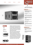
CD12 HyperCardoid Subbass. Two 12” (30cm) Long Excursion Neodymium 6 Ohm Drivers,
each controlled by one DSP channel, creating a 120° x 120° hypercardioid pattern. Can be
flown or ground-stacked.
•
NX242 Digital TDcontroller. Provides comprehensive control of the above GEO S Series
loudspeakers in multiple configurations. For a complete description of this unit, please refer
to the NX242 User Manual. Please remember that the NX242 Digital TDcontroller’s DSP
algorithms and parameters are software and are updated regularly. Please consult the
NEXO web site (www.nexo.fr or www.nexo-sa.com) for the latest software releases.
•
GEO Flying System. Coupled with the integral array assembly system on GEO S Series
cabinets, provides safe, flexible and simple means of flying GEO Tangent Arrays. NOTE:
GEO Tangent Arrays control the dispersion of acoustic energy with a high degree of
precision. Inclinometers and laser aiming devices are essential to ensure proper audience
coverage when hanging or flying a GEO Tangent Array.
•
GEOSoft2 Array Design Software. MATLAB based Windows software simplifies the design
and implementation of vertical tangent GEO arrays.
Please devote some attention to reading this manual. A comprehensive understanding of GEO
waveguide theory, tangent arrays, and specific features of the GEO S Series will help you to operate
your system at its full potential.
GENERAL SET-UP INSTRUCTIONS
P.5
GENERAL SET-UP INSTRUCTIONS
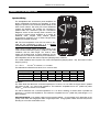
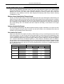
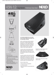
Speaker Wiring
The loudspeakers are connected to power amplifiers via
NL4FC SPEAKON connectors (not supplied). A wiring
diagram is printed on the connection panel located on the
back of each cabinet. The in/out pins of the SPEAKON
sockets are identified. The sockets are connected in
parallel within the enclosures (see the Connections
Diagrams section of this manual). Either connector can
be used to connect power amplifiers or to power an
additional GEO Tangent Array Module (NEXO
recommend a maximum of six S Series Tangent Array
Modules per amplifier channel).
NB: The front loudspeaker of the CD12 is wired 2+ & 2while the rear loudspeaker is wired 1- & 1+. NEVER
connect the CD12 to the GEO S805/S830.
Cable choice consists mainly of selecting cables of the
correct sectional dimension (size) in relation to the load
resistance and the cable length. Too small a cable
section will increase both its serial resistance and its
capacitance; this reduces the electrical power delivered to
the loudspeaker and can also induce response (damping factor) variations.
For a serial resistance less or equal to 4% of the load impedance (damping factor = 25), the maximum cable
length is given by:
Lmax = Z x S
S in mm2, Z in Ohms, Lmax in meters
The table below indicates these values, for 3 common sizes.
Load Impedance (Ω)
2
Cable section
Maximum Length (meters)
3
4
6
8
12
16
1,5 mm² (AWG #14)
3
4.5
6
9
12
18
24
2,5 mm² (AWG #12)
5
7.5
10
15
20
30
40
4 mm² (AWG #10)
8
12
16
24
32
48
64
Examples :
The GEO S805 and S830 have a nominal impedance of 16 ohms, so a 6x GEO S8 cluster wired in parallel
will present a 16/6 = 2.7 Ohms load impedance. The maximum acceptable 2x2.5 mm2 (AWG #12) cable
length Lmax for such a cluster is 6.75 meters.
The CD12 subwoofer has a nominal impedance of 2 x 6 Ohms, therefore 2 CD12s wired in parallel will
present a 2 x 3 Ohms load impedance. The maximum acceptable 4x4 mm2 (AWG #10) cable length Lmax is
then 12 meters.
IMPORTANT NOTE: Long speaker cables induce capacitive effects – up to hundreds of pF depending on the
quality of the cable, with a high-pass effect in high frequencies. If long speaker cables must be used, ensure
that they do not remain coiled while in use.
P.6
GENERAL SET-UP INSTRUCTIONS
Amplifier Selection
Power
GEO S8 Series array elements are rated for 500 Watts power handling. Although each array element has a
16 Ohm nominal impedance, NEXO recommends that you connect no more than six S8 Series array
elements to a single amplifier channel. The amplifiers used for this application should be capable of delivering
1500 to 3000 Watts into a low impedance (typically specified as 2 Ohm) load. Budget constraints are the only
reason to select lower output power amplifiers. A lower power amplifier will not reduce the chances of driver
damage due to overexcursion, and may actually increase the risk of thermal damage due to sustained
clipping.
The CD12 requires two amplifier channels delivering separately processed signals to produce its
hypercardioid pattern. The amplifier model should be the same as that used for the GEO S8 Series array
elements. Two CD12s can be connected in parallel: take care that both front woofers and both rear woofers
are connected in parallel.
Current rating
It is very important that the amplifier behaves correctly under low load conditions. A speaker system is reactive
by nature: on transient signals like music it will require four to ten times more instantaneous current than its
nominal impedance would indicate. Amplifiers are generally specified by continuous RMS power into resistive
loads, however the only useful information about current capacity is the specification into a 2 Ohm load. It is
possible to perform an amplifier listening test by loading the amps with twice the number of cabinets
considered for the application (2 speakers per channel instead of one, 4 instead of 2) and running the amps
up to the onset of clipping. If the signal does not noticeably deteriorate, the amplifier is well adapted
(overheating after approximately ten minutes is normal but thermal protection must not operate too quickly
after starting this test).
Amplifier gain settings
Technical knowledge of the amplifiers to be used with the system is essential. This data is the key to the
correct alignment of the system. It is especially important to know the gain of all amplifiers used in your set-up.
The tolerance should be about ±0.5 dB. In practice this can be difficult to achieve because:
•
Some amplifier brands have an identical input sensitivity for models of different power rating
(this infers a different voltage gain for each model). For example, a range of amplifiers with
different power outputs, all having a published input sensitivity of 775mV/0dBm or
1.55V/+6dBm, will have a wide range of actual gains – the higher the power, the greater the
gain.
•
Various other brands may offer constant gain but only within a given product range, for
example they may fit fixed input sensitivity only on their semi-professional amps.
•
Even if a manufacturer applies the constant gain rule to all models, the value selected will
not necessarily be the same as that chosen by other manufacturers.
•
Some products can exhibit manufacturing tolerances for the same model of ±1dB or more.
Some amplifiers may have been modified, possibly without any label indicating the new
values. Others may have gain switches fitted internally where it is impossible for the user to
verify the actual setting without opening the amplifier casing. In cases where you don't know
the gain of your amplifier (or want to check it) please follow this procedure:
1) Unplug any loudspeakers from the amplifier outputs
2) With a signal generator, feed a sine wave at 1000Hz at a known voltage (say 0.5V) to
the input of the amplifier under test
3) Measure the voltage at the output of the amplifier
4) Calculate the gain using the formula Gain = 20 * LOG10(Vout/Vin).
GENERAL SET-UP INSTRUCTIONS
P.7
Some examples:
Gain
20dB
26dB
32dB
37dB (1.4V sensitivity / 1350Wrms)
0.1V
1V
2V
4V
7.1V
0.5V
5V
10V
20V
35.4V
1V
10V
20V
40V
70.8V
Vin
Remember that constant sensitivity settings will give a different gain value when the amplifier power is
different.
Gain value
NEXO recommends low gain amplifiers: +26dB is recommended, as it is at the same time adequately low and
quite common amongst amplifier manufacturers. This gain setting improves signal to noise ratio and allows all
preceding electronic equipment, including the NX242 TDcontroller, to operate at optimum level. Remember
that using a high gain amplifier will raise the noise floor proportionally.
Advanced protection
Some high-end amplifiers may include signal processing functions similar to those found in the NX242
TDcontroller ("loudspeaker offset integration", "limiter", "compressor," etc.). These functions are not adapted to
specific system requirements and may interfere with the complex protection algorithms used in the NX242.
NEXO do not advise using other protection systems in conjunction with the NX242 and they should be
disabled.
Connection Diagrams
The NX242 TDcontroller provides two basic modes of operation with GEO S Series products, as shown
below.
1)
Stereo GEO S8 with no CD12 sub,
2)
Mono GEO S8 with CD12 Sub.
P.8
NX242 DIGITAL TDCONTROLLER SETTINGS
NX242 DIGITAL TDCONTROLLER SETTINGS
The GEO S Series cabinets will not perform correctly without the NX242 TDcontroller. Sound quality and
reliability are totally dependent on the correct use of the NX242 TDcontroller, in accordance with the
instructions provided in this manual and in the NX242 User Manual.
All manuals & associated technical notes must be read before set-up. Please contact your NEXO agent for
any literature you may need. The NX242 Digital TDcontroller is able to drive the entire current NEXO range
(GEO, PS & Alpha series, CD12 subs). The following GEO set-ups are examples, for a complete and updated
list please refer to the documentation describing the NX-LOAD.
GEO Vertical Arrays
Input/Output Assignments:
GEO S8 Series Wideband Configurations (No Sub)
Input A
Input B
Left
Right
Output 4 HF
Output 3 HF
Output 2 LF
Output 1 Sub
Left
Right
No Signal
No Signal
S805 4-8 boxes No Sub
Stereo Setup. Input A (Left) & B (right). Output 3 (left) and 4 (right). No signal on output 1 &2.
Configure GEO S805 Wideband for 4-8 boxes.
S805 9-16 boxes No Sub
Stereo Setup. Input A (Left) & B (right). Output 3 (left) and 4 (right). No signal on output 1 &2.
Configure GEO S805 Wideband for 9-12 boxes.
Input/Output Assignments: GEO S8 + CD12 Configurations
Input A
Input B
Mono
No Signal
Output 4 HF
Output 3 HF
Output 2 LF
Output 1 Sub
No Signal
GEO S8
CD12 Front Driver
CD12 Back Driver
S805 4-8 boxes CD12 Ground
Mono Setup. Input A. Output 1 (back driver of the CD12), Output 2 (front driver of the CD12), Output 3 (GEO),
no signal on Output 4.
Configure GEO S805 (4-8 boxes) with CD12.
S805 9-6 boxes CD12 Ground
Mono Setup. Input A. Output 1 (back driver of the CD12), Output 2 (front driver of the CD12), Output 3 (GEO),
no signal on Output 4.
Configure GEO S805 (9-16 boxes) with CD12.
S805 4-8 boxes CD12 Flown
Mono Setup. Input A. Output 1 (back driver of the CD12), Output 2 (front driver of the CD12), Output 3 (GEO),
no signal on Output 4.
Configure GEO S805 (4-8 boxes) with CD12 flown.
NX242 DIGITAL TDCONTROLLER SETTINGS
P.9
S805 9-16 boxes CD12 Flown
Mono Setup. Input A. Output 1 (back driver of the CD12), Output 2 (front driver of the CD12), Output 3 (GEO),
no signal on Output 4.
Configure GEO S805 (9-16 boxes) with CD12 flown.
GEO Horizontal Tangent Arrays
Input/Output Assignments: GEO S8 Series Wideband
Configurations (No Sub)
Input A
Input B
Left
Right
Output 4 HF
Output 3 HF
Output 2 LF
Output 1 Sub
Left
Right
No Signal
No Signal
S830 3 boxes No Sub
Stereo Setup. Input A (Left) & B (right). Output 3 (left) and 4 (right). No signal on output 1 &2.
Configure three GEO S830 Wideband.
Input/Output Assignments: GEO S8 + CD12 Configurations
Input A
Input B
Mono
No Signal
Output 4 HF
Output 3 HF
Output 2 LF
Output 1 Sub
No Signal
GEO S8
CD12 Front Driver
CD12 Back Driver
S830 3 boxes CD12 Flown
Mono Setup. Input A. Output 1 (back driver of the CD12), Output 2 (front driver of the CD12), Output 3 (GEO),
no signal on Output 4.
Configure three GEO S830 with a CD12 flown.
S830 3 boxes CD12 Ground
Mono Setup. Input A. Output 1 (back driver of the CD12), Output 2 (front driver of the CD12), Output 3 (GEO),
no signal on Output 4.
Configure three GEO S830 with a CD12 ground.
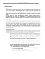
Speaker Quantity
Speaker Quantity (MENU 1.7)
parameter acts on an Array
EQ that has been tuned to
reduce the coupling effect of
multiple GEO cabinets at Low
Frequencies. It will help you
to fine tune your system
according to the number of
cabinets and personal taste.
Array EQ is at 0dB when
Spekaer Quantity is 8, boosts
for lower quantities, and cuts
for higher quantities.
P.10
NX242 DIGITAL TDCONTROLLER SETTINGS
Delays & System Alignment
The NX242 internal time adjustments (factory presets) have been optimised to provide the best crossover
possible between the MAIN and SUB systems. The reference point for this adjustment is the front side of
each cabinet. (That means that the internal delays are set for a S8 cabinet standing close to the CD12, with
both front sides being aligned).
Should you rig your CD12 behind the S8, you will have to delay the MAIN system the according distance D.
The delay parameter is set in MENU 1.2 (set the units to meters or feet according to your preference).
Should you leave your CD12 on the ground, you will have to adjust the delay on the CD12 (using MENU 1.2)
according to the path difference between the flown GEO and the ground stacked CD12. We recommend you
to adjust your system for the more distant listening point.
In the following case where A is the average height, B the listening point and C the difference between front
sides of both systems
CD12 Delay =
A2 + B 2 − B ± C (specify meters or feet)
If this formula gives a negative result the delay should be implemented on the MAIN channel.
D
A
B
+C
-C
Initial Set-up Precautions
When running up a system that includes new cabinets for the first time, the power should be increased slowly
to approximately 50% and the system operated at this level for two hours. During the following two hours of
operation the power level should be limited to approximately 75%. This procedure allows the adhesives and
suspensions within the loudspeaker components to stabilise and will extend their working life.
In all cases, it is advisable to connect the loudspeakers only after all the other components have been wired
and are operating correctly. This is particularly important for the amplifiers and the TDcontroller. It is a good
practice to turn down all the amplifier gains before connecting the cabinets and then turn them up again
individually with a medium level music source fed into the system. The sense LEDs of the corresponding
TDcontroller channel should light up accordingly. This will help to locate cabling errors, particularly channel
line inversions, which would disable the TDcontroller protections and may invalidate the warranty.
IMPORTANT
If more than one amplifier is being driven from an output of the NX242 TDcontroller, only those amplifiers that
are not connected to sense inputs may be attenuated. If the sensed amplifier is attenuated and the slave
amplifiers are not, severe system damage will result!
DEPLOYING GEO TANGENT ARRAYS
P.11
DEPLOYING GEO TANGENT ARRAYS
Vertical vs. Horizontal
One of the advantages of the GEO S Series is the ability to construct coherent vertical and horizontal arrays
from the appropriate GEO Tangent Array Modules. These two types of arrays are very different in their
behaviour and intended applications.
Vertical tangent arrays of GEO are intended for applications where the horizontal coverage (80 or 120º) is
suitable for the application and even SPL from the first row to the last row of the audience is desired. The
GEOSoft2 software will help you design a vertical array of S805 and S830 cabinets and tailor the acoustic
wave generated by the cluster to fit your audience profile, providing equal power to equal areas. When done
properly, the GEO S Series can provide extremely even SPL throughout the depth of your audience, including
balcony coverage.
Horizontal tangent arrays of GEO S830 cabinets provide exceptional control of horizontal coverage but are
not intended to provide the same even SPL capability as a vertical array. Horizontal arrays deliver equal
power to equal angles, with SPL decreasing as you move further back in the audience. However, the GEO
S830 is designed to array tangentially with adjacent S830 cabinets providing a much more coherent wave
front from an array of multiple cabinets than conventional arrayable cabinets. This allows the user to provide
30º increments of horizontal coverage as needed.
CD12 HyperCardioid Subbass
The CD12 is a hypercardioid subbass device providing directional low frequency energy with a dramatic
reduction in low frequencies behind the loudspeaker(s). This is achieved using the interaction of two
independently driven 12” drivers, highly specialized ports, and the digital processing capabilities of the NX242
Loudspeaker Controller.
It is important to follow these guidelines to attain the best performance from the CD12;
•
Keep at least 3’ to 4’ (1m) of space around the CD12(s) when they are located on the
ground. Objects or barriers within this space can interfere with the interaction of wave fronts
from the front and rear of the CD12.
•
Drive the front and rear drivers with identical amplifier channels set to the same gain. The
operation of the CD12 is based on the assumption that both the front and rear sub-systems
are identical in terms of the amplifier’s electrical performance.
•
When flying the CD12(s), use the linking bar to connect the CD12 bumper to the GEO
Bumper and keep at least 50cm (~20”) of space between the back of the GEO cabinets and
the front of the CD12(s).. It provides enough distance that the GEO cabinets will not
interfere with the acoustical wave front from the CD12. For time alignment with the main
system see page 10 “Delays & System Alignment”
•
When ground stacking the CD12, it is better to stack them vertically than horizontally.
•
When hanging or stacking multiple CD12 cabinets make sure they are all oriented correctly;
fronts forward and tops up. Do not hang one CD12 upside down relative to the others.
P.12
GEOSOFT2
GEOSOFT2
GEOSoft2 software processes measured speaker data with complex mathematical algorithms to assist the
user in designing vertical tangent GEO arrays that provide even SPL throughout the depth of the audience.
Due to the complexity of the interaction of multiple cabinets, it is simply not possible to reliably design curved
vertical arrays without using the processing power of a computer to predict the optimum array structure for a
given audience geometry. The design logic is far more complex than looking at a section drawing of the
venue, measuring the overall angle needed to cover the audience from your cluster location, and dividing by
5º to determine the number of S805 cabinets you will need.
GEOSoft2 is an easy to use tool that will allow you to shape the energy leaving the cluster to fit your audience.
In addition you will be able to predict the average and peak SPL of the system to ensure you have provided
enough cabinets for the application.
GEOSoft2 is used only for determining the structure of the cluster to attain proper coverage in the vertical
plane. In the horizontal plane, you project 80º, 100º, or 120º degrees of horizontal coverage from your cluster
locations on a plan view of the venue to determine optimum locations for your hanging points.
For a more complete and up-to-date information, Geosoft2 can be downloaded from Nexo’s website
www.nexo-sa.com. Please check that link for application examples and latest upgrades periodically.
USING THE CONFIGURABLE DIRECTIVITY DEVICE
P.13
USING THE CONFIGURABLE DIRECTIVITY DEVICE
The GEO Wavesource controls dispersion of acoustic energy using an hyperboloid acoustical reflector in the
“coupling plane” (the vertical plane of a curved vertical tangent array) and a diffraction slot in the “non-coupling
plane” (the horizontal plane of a curved vertical tangent array). The patent-pending Configurable Directivity
Device consists of bolt-on flanges that alter the diffraction slot’s exit flare rate. The flanges look like this:
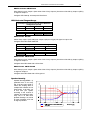
In the graph below, the red curve shows the dispersion in the non-coupling plane with the flanges installed:
the narrower blue curve shows the dispersion without the flanges.
COVERAGE ANGLE (Degree)
180°
120°
Angle [°]
60°
0°
−60°
−120°
−180°
1k
10k
Freq [Hz]
GEO Hyperboloid Reflective Wavesource
with Configurable Directivity Device flanges
Non-coupling plane dispersion vs. frequency, with
(120° black) and without (80° grey) Configurable
Directivity flanges installed
Installing & removing GEO’s Configurable Directivity flanges
GEO S805 are shipped in the 80° dispersion (without the flanges installed). GEO S830 Series loudspeakers
are shipped with the flanges installed (120° dispersion in the non-coupling plane). To remove the flanges for
narrower 80° dispersion in the non-coupling plane, remove the front grill and the four TORX (head 25) screws
in each side of the GEO Wavesource. Store these screws with the flanges. To fill in the holes, use the shorter
replacement screws provided with your GEO S8 Series loudspeaker. Do not attempt to screw the longer
flange attachment screws into the waveguide attachment points: this will damage your GEO S8 Series
loudspeaker’s Hyperboloid Reflective Wavesource.
NOTE: A torque of 1N.m maximum shall be applied to the screw. NEVER USE POWER TOOLS TO
INSTALL OR REMOVE CDD FLANGES: THEIR EXCESSIVE TORQUE CAPABILITY CAN EASILY
DAMAGE THE GEO WAVESOURCE.
M5x12
M5x25
P.14
USING THE CONFIGURABLE DIRECTIVITY DEVICE
When & where to use Configurable Directivity flanges
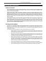
The diagram below can be considered as a plan view of the audience area shown in Figure 1. Instead of
looking through the sidewall, we are looking through the ceiling. While the GEO cluster will deliver even SPL
from the front to the rear of this audience area, there are “holes” near the front in the centre and at the outside
edges. We cannot fill the outside coverage gaps without enlarging the centre gap, and vice versa.
- Figure 1 :Plan view of coverage using two GEO curved vertical arrays
without Configurable Directivity flanges
- Figure 2 : Plan view of coverage using two GEO curved vertical
arrays. Both Configurable Directivity flanges have been installed in
the bottom two cabinets of the clusters.
However, if we install Configurable Directivity Devices in the bottom two cabinets of the cluster, coverage will
look more like the pattern in Figure 2.
In curved vertical arrays, the Configurable Directivity Device can be used:
•
On the bottom two rows of curved vertical arrays, to fill in coverage gaps in the front rows.
•
On all rows of curved vertical arrays, in cases where 240° of horizontal coverage is preferred to
160°.
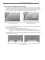
In horizontal arrays of GEO S830s, the Configurable Directivity Device can be removed to narrow the vertical
coverage of the array from 120° to 80°.
- Sectional view of a 100’ deep space, showing coverage alternatives using GEO S830 arrays aimed straight down, with (right) and
without (left) CDD flanges.
GEO APPLICATION GUIDELINES
P.15
GEO APPLICATION GUIDELINES
GEO is a highly adaptable and flexible system due to the unique performance factors of the patent-pending
Hyperboloid Reflective Wavesource, the Configurable Directivity Device flanges and other innovations.
However, like all tools, your GEO system has been designed to function in specific ways: these lend
themselves to many situations, but not all. When designing and deploying GEO arrays, keep the following
considerations in mind.
Minimum Array Height (Vertical Tangent Arrays)
Like any “line array,” GEO’s ability to control lower frequencies with longer wavelengths is determined by the
height of the array. NEXO recommend that curved vertical GEO tangent arrays include at least four (4) S805’s
and one (1) S830. Lines shorter than this will not provide adequate control of lower frequencies. You will see
this in GEOSoft2: the black dBA trace will curve downward and will approach the red HF trace towards the
rear of the listening area. This indicates that lower frequencies are falling in level relative to the higher
frequencies.
Optimum Height of the Bumper
Can be found by experimenting with different heights and aiming angles in GEOSoft2. Your system can also
be ground staked by using the proper accessory and the later revision of the GEOSoft2 which allow the
simulation of ground-stacked GEO vertical arrays.
How Loud for the Crowd?
Keep in mind that due to the superior coherency of GEO arrays, you may not need to get as loud in order to
“hear what is going on” as was the case with previous generations of sound reinforcement loudspeakers using
coercive megaphone-variant horn designs. The following chart offers some guidelines about the capability of
curved vertical GEO tangent arrays of various lengths. Maximum values in dBA are for all cabinets angled at
0.31°, minimum values are for all cabinets angled at 5° ; these values are calculated for open air conditions.
For an audience of the indicated total length, the ±3 dB value will probably fall somewhere in between the Min
and Max values. So a four-tall vertical tangent array, you will be able to produce levels of between 105 dBA
and 110 dBA from the front to the rear of a 10m long audience area, and from 87 to 92 dBA throughout an
80m long audience area.
GEO Array
Array Length
4 x S805
8 x S805
12 x S805
16 x S805
Output ±3 dB
Total Length of Audience Area
10 meters
20 meters
40 meters
80 meters
dBA Min
105
99
93
87
dBA Max
110
104
98
92
dBA Min
106
100
94
88
dBA Max
111
108
104
98
dBA Min
107
101
95
89
dBA Max
111
108
105
100
dBA Min
107
102
96
90
dBA Max
113
110
107
104
P.16
GEO TANGENT ARRAY RIGGING SYSTEM
GEO TANGENT ARRAY RIGGING SYSTEM
Before proceeding with assembly of GEOS / CD12 arrays, please ensure that the components are present
and undamaged. A component list is appended to this manual. In the event of any shortage, please contact
your supplier.
SAFETY FIRST
GeoS / CD12 Rigging System has been approved by Certification Organization RWTÜV. Structural
computations, test reports, certificates are available in Geosoft2 or at Nexo ([email protected]) upon request.
We include this section to remind you of safe practice when flying the GEOS / CD12 system. Please read it
carefully. However, user must always apply his or her knowledge, experience and common sense. If in any
doubt, seek advice from your supplier or NEXO agent.
This manual offers guidance only for GeoS / CD12 loudspeaker systems. References in this manual to other
rigging equipment such as motor hoists, steels, shackles etc. are made to clarify the description of GeoS /
CD12 procedures. The user must ensure that operators are properly trained by other agencies in the use of
these items.
The GEOS / CD12 Rigging System has been optimised for the deployment of curved vertical tangent arrays
of GEO S805 / S830 / CD12 loudspeakers. Vertical angle adjustment between cabinets has been limited to
specific settings to ensure correct acoustic coupling.
The GEOS / CD12 Rigging System is a professional precision tool set, and should be handled with extreme
care. Only persons who are fully conversant with the operation of the GEOS / CD12 Rigging System and
provided with suitable safety equipment should deploy GEO Arrays. Misuse of the GEOS / CD12 Rigging
System could lead to dangerous consequences. Please refer to the safety section of this manual for advice
concerning GEOS / CD12 Rigging System installation and handling.
Used and maintained correctly, the GEOS / CD12 Rigging System will give many years of reliable service in
portable systems. Please take the time to read and understand this manual. Always use GEOSoft2 to
determine the optimum angle settings for a particular venue, hang point and curved vertical GEOS / CD12
array. Applied forces and moments are strongly cabinet quantity and angle configuration dependent. Cluster
configuration must be implemented and validated in Geosoft2 prior to installation.
Flown Systems Safety
•
Always inspect GEOS / CD12 Rigging System components for damage before assembly.
Pay special attention to lifting points and safety clips. If you suspect that any of the
components are defective DO NOT USE THE AFFECTED PARTS. Contact your supplier
for replacements.
•
Read this manual carefully. Also be familiar with the manuals and safe working procedures
for any ancillary equipment that will be used with the GEOS / CD12 Rigging System.
•
Ensure that all local and National regulations regarding the safety and operation of flying
equipment are understood and adhered to. Information on these regulations may usually be
obtained from Local Government Offices.
•
When deploying the GEOS / CD12 Rigging System always wear protective headgear,
footwear as well as eye protection.
•
Do not allow inexperienced persons to handle the GEOS / CD12 Rigging System.
Installation personnel should be trained in loudspeaker flying techniques and should be fully
conversant with this manual.
•
Ensure that motor hoists, hoist control systems and ancillary rigging components are
currently certified as safe and that they pass a visual inspection prior to use.
•
Ensure that public and personnel are not allowed to pass beneath the system during the
installation process. The work area should be isolated from public access.
GEO TANGENT ARRAY RIGGING SYSTEM
P.17
•
Never leave the system unattended during the installation process.
•
Do not place any object, no matter how small or light, on top of the system during the
installation procedure. The object may fall when the system is flown and is likely to cause
injury.
•
Motor or hoist secondary safety steels must be installed once the system has been flown to
the operating height. Secondary steels requirements depend on the local safety standards
applicable to the territory.
•
Ensure that the system is secure and prevented from pivoting around the motor hoist.
•
Avoid any form of excessive dynamic loading to the assembly (structural computations on
GeoS Rigging System are based on a 1/1.2 factor for hoist or motor acceleration).
•
NEVER attach any item to the GEOS / CD12 system other than NEXO GEOS / CD12
accessories.
•
When flying outdoor systems ensure that the system is not exposed to excessive wind or
snow loads and is protected from rainfall.
•
The GEOS / CD12 Rigging System requires minimum yearly inspection by a competent
person. Please follow local regulations for inspection procedures.
•
When de-rigging the system ensure that the same care is given to the load out procedure
as for installation. Pack GEOS / CD12 Rigging System components carefully to prevent
damage in transit.
Ground Stacking Safety
Statistically, many more injuries occur due to unstable ground stacked PA systems than those associated with
flown systems. There are several reasons for this fact, however the message is clear:
•
Always survey the supporting structure upon which a ground stack is to be built. Always
look beneath PA wings to inspect the deck support and if necessary ask for the stage
scrims and dressings be removed to allow access.
•
If the stage surface slopes, as it does in some theatres, ensure that the system is prevented
from sliding forwards due to vibration. This may require the fitting of timber battens to the
stage floor.
•
For outdoor systems ensure that that the system is protected from wind forces which might
cause the ground stack to become unstable. Wind forces can be huge, especially upon
large systems, and should never be underestimated. Observe meteorological forecasts,
calculate the “worst case” effect upon the system prior to erection and ensure that the
system is secured appropriately.
•
Take care when stacking cabinets. Always employ safe lifting procedures and never attempt
to build stacks without sufficient personnel and equipment.
•
Never allow anyone, whether operators, artists or members of the public to climb onto a
ground stacked PA system. Anyone who needs to climb over 2m high should be fitted with
suitable safely equipment including a clip-on harness. Please refer to local Health and
Safety legislation in your territory. Your dealer can help with advice on access to this
information.
•
Apply the same attention to all safety matters when de-stacking systems.
•
Be aware that safety procedures are as important in the truck and in the warehouse as they
are at the venue.
P.18
GEO TANGENT ARRAY RIGGING SYSTEM
Contacts
Correct training is fundamental to safe practise when working with loudspeakers flying systems. NEXO
recommend that users contact local industry associations for information on specialist course.
Information for International training agencies can be obtained by contacting either:
The Production Services Association (PSA),
School Passage,
Kingston-upon-Thames,
KT1 SDU Surrey,
ENGLAND
Telephone: +44 (0) 181 392 0180
Rigstar Training and Testing Center
82 Industrial Dr. Unit 4
Northampton, Massachusetts 01060 U.S.A.
Phone: 413-585-9869 -- Fax: 413-585-9872
[email protected]
ESTA
Entertainment Services & Technology Association
875 Sixth Avenue, Suite 1005
NEW YORK, NY 10001 USA
Phone: 212-244-1505 – Fax: 212-244-1502
[email protected] - www.esta.org
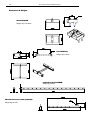
GEO Loudspeakers
Front connection
point
Angle setting plate
Pivot point
Angle setting bar
Avoids the bar
of the last cabinet to fall
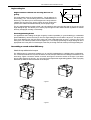
GEO S850 and S830 Tangent Array Modules are shipped from the factory with identical array assembly
hardware. The GEO Tangent Array Assembly System has three attachment points on each side. The points
in the front connect each GEO cabinet to the adjacent enclosures above and below. The angle between
cabinets is set by attaching one end of the angle-setting bar to the proper hole on the angle-setting plate,
which extends beyond the rear of the cabinet.
The front connection points and the angle-setting holes in the angle plate are milled for the supplied pins,
which have a diameter of 8 mm. Possible replacements for specific applications include:
•
Nuts and bolts with a diameter of 8mm or 5/16 in. (7.94 mm) for fixed installation
•
8mm (NEXO REF: BLGEOS) or 5/16 in pins with spring-loaded locking balls for quicker
array assembly and disassembly in portable applications.
GEO TANGENT ARRAY RIGGING SYSTEM
P.19
Angle-setting bar
Angles between cabinets are set using the force of
gravity
The angle setting pivots on the hole marked 1. For all angles up to
and including 17.5°, use the oblong hole on the unattached end of
the bar (A). This allows you to set the angles of the array while the
cabinets are lying flat on the ground. When the array is lifted into
position each cabinet will fall automatically into the proper angle.
The 30° angle adjustment is always fixed, use hole marked 2, and is set using the hole on the very end of the
angle-setting bar (B). This allows you to set the proper angles for GEO S830 cabinets regardless of whether
the array is deployed vertically or horizontally.
Fixed Angle-Setting Points
For applications where setting the angles via gravity is either impossible (i.e. ground stacking) or undesirable
(fixed installations), remove the front pin from the angle-setting bar and re-attach it at point 2. This pivot point
is the same distance from the hole at the other end of the angle-setting bar as point 1 is from the end of the
oblong slot. This makes it possible to set all angles up to 17.5° directly by attaching the angle-setting bar to the
appropriate hole in the plate. For fixed angles, insert the pin through the hole at the tip of the angle-setting bar.
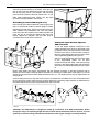
Assembling a curved vertical GEO array
Attach the top cabinet to the bumper
The GEO Bumper is symmetrical, enabling you to use GEO loudspeakers in a left/right stereo configuration.
The connection between the top GEO enclosure and the bumper determines the left/right orientation for the
entire array. Figure 3 shows the woofer on the left, and Figure 4 shows the woofer on the right. If you attach
the top GEO enclosure in this way, you must remove and replace the angle-setting plates in order to properly
attach the top GEO enclosure at the rear of the bumper.
- Figure 3
- Figure 4
P.20
GEO TANGENT ARRAY RIGGING SYSTEM
After having positioned the top enclosure, insert the pins
into the front and rear attachment points and lock them
with R clips (see picture). The bumper’s rear mounting
point should be connect to the hole marked “LIFT” on the
GEO Angle Adjustment Plate. NOTE: The top GEO
enclosure is always parallel to the bumper.
Assembling a vertical GEO tangent array
Place the top GEO cabinet (attached to the bumper) face
down on a horizontal surface (a narrow length of carpet
will help protect the grills). Align the top holes of the next
GEO cabinet’s front attachment bar with the bottom
holes of the first GEO cabinet’s front attachment bar and
insert the pins to connect both sides at the front (see
below). Repeat this operation until the entire array is
connected at the fronts of the enclosures.
Lift
Setting the angles between adjacent
GEO enclosures
To set the angles between enclosures to the
values specified for this array by GEOSoft2, begin
by lifting the array until only the bottom enclosure
remains on the ground. This will make it easier to
align the angle-setting bars with the proper holes
in the angle-setting plates (see Figure 5).
Align the angle-setting bars with the proper holes
in the angle-setting plates. For all GEO
enclosures except the S830, insert pins through
the hole in the angle-setting plate and the oblong
slot at the end of the angle-setting bar (see Figure
6).
NOTE: GEO S830’s are always “tight-packed” with the adjacent enclosure so that the wavefronts will be
tangent and will combine coherently without interference. The angle of a GEO S830 at the bottom of a curved
vertical array and just below a GEO S850 will therefore be 17.5°. The angle between any two GEO S830’s will
always be 30°.
Continue lifting the array so that the fronts of all the enclosures are accessible, then lock all the attachment
pins in place with R-clips. While the array is being raised to the operating height specified by GEOSoft2, the
enclosures will fall into the proper angular alignment with each other.
- Figure 6
- Figure 5
CAUTION: The GEO Bumper is designed to safely fly a maximum of 24 GEO loudspeakers. Before
raising the array to its operating height, be sure to check that all attachment pins are in place, secured
by R-clips or another locking mechanism and that both sides angles settings are strictly identical.
GEO TANGENT ARRAY RIGGING SYSTEM
P.21
Extension Bar
- Figure 7
- Figure 8
The GEO Bumper has two lift points, which are adequate for many situations. The extension bar is designed
for those applications where the bumper’s lift points are too close together to allow setting the proper tilt angle
for the entire array. With 16 GEO cabinets, a vertical GEO array can be tilted ±15°. NOTE: Always use an
inclinometer and/or a laser aiming device to verify that the array has the tilt angle specified in GEOSoft2.
The extension bar has several tilt-angle adjustment points. It must always be secured by inserting two of the
supplied 12mm pins into two of these points: pins must be locked in place with the supplied R-clips. The GEO
bumper, with or without the extension bar, should be lifted by a single motor hoist using the two adjustable
chains connected to a central flying ring (see Figure 8).
CD12 BUMPER
The bumper of the CD12 is an independent hardware element that enables GEO users to fly one or more
CD12’s either alone or directly behind a GEO array. The CD12 bumper is shipped with four link steels. To
connect the top CD12, attach these steels to the four rails located on the bumper and the four rails located on
the CD12 (Figure 9).
- Figure 9
P.22
GEO TANGENT ARRAY RIGGING SYSTEM
Combination GEO/CD12 bumper
It is possible to make a single bumper by using the connecting bar to join the GEO bumper and the CD12
bumper. The cluster will then consist of:
•
The GEO enclosures, attached to the GEO bumper
•
The CD12 enclosures, attached to the CD12 bumper directly behind the GEO array
•
The connecting bar which joins the entire array assembly together.
The procedures for attaching GEO loudspeakers and CD12 enclosures to their respective bumpers are the
same as previously explained.
The connecting bar must be passed through the bodies of both bumpers and locked in position using two
12mm pins for each bumper. These 12mm pins use the same R-clips as on the GEO pins (see Figure 10).
NOTE: The list points of the CD12 Bumper are positioned on the centre of gravity of the CD12. They are
offset from the centre of the tube to allow the correct positioning when assembling a combination GEO/CD12
bumper.
If you are assembling left/right stereo arrays as described in section IV-1, you must reverse the CD12 bumper
in order to maintain the correct orientation with respect to the GEO Array. In a frontal view of the cluster, the
GEO array must be centred with respect to the CD12. (see Figure 11).
CAUTION: In this configuration, the CD12 Bumper is designed to hang a maximum of 8 CD12
enclosures.
- Figure 10
- Figure 11
GEO TANGENT ARRAY RIGGING SYSTEM
P.23
Assembling Horizontal GEO Arrays
Horizontal GEO arrays are composed exclusively of GEO S830 loudspeakers.
In this configuration, it is imperative that the cabinets are “tight packed,” that is arrayed at 30° splay angles,
matching the trapezoidal sides of the GEO S830 enclosures. This ensures that the wavefronts are truly
tangent and combine without destructive interference.
Up to three Horizontal GEO S830 arrays can be well hung by using the accessory GEOS-HRPL, attached to
the GEO Array Assembly System with 8mm rings and locking nuts. Always use the “LIFT” point for the rear
attachment. To vary the vertical angle of the array, use different points for the front attachment. For mounting
instruction, please refer to the document shipped with the accessory.
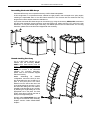
Ground stacking Geo Array
Up to 8 GEO S805 cabinets can be
stacked with the accessory GEOSGRND. GEO S830 should never be
ground stacked together with GEO
S805. The stacking configuration is
taken into account in the GEOSoft2
software. For mounting instruction,
please refer to the document shipped
with the accessory.
Before
assembling
for
stacked
configuration, remove the front pin from
the angle-setting bar and re-attach it at
point 2. This pivot point is the same
distance from the hole at the other end
of the angle-setting bar as point 1 is from
the end of the oblong slot. This makes it
possible to set all angles up to 5° directly
by attaching the angle-setting bar to the
appropriate hole in the plate. For fixed
angles, insert the pin through the hole at
the tip of the angle-setting bar.
Properly adjust GEOS-GRND front and
rear legs so that GEOS stack assembly
footprint remains inside GEOS-GRND
footprint.
P.24
GEO TANGENT ARRAY RIGGING SYSTEM
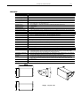
Dimensions & Weights
GEOS-BUMPER
Weight 11kg / 24.25 lbs
CD12-BUMPER
Weight 15kg / 33 lbs
Link BAR (CD12-LINKBAR)
Weight 9kg /19.8 lbs
GEO/CD12 Extension BAR (EXBAR-S)
Weight 4kg / 8.8 lbs
TECHNICAL SPECIFICATIONS
P.25
TECHNICAL SPECIFICATIONS
GEO S805
SYSTEM SPECIFICATIONS
GEO S805 with NX242 TDcontroller
Frequency Response [a]
67 Hz – 19 kHz ± 3 dB
Usable Range @-6dB [a]
60 Hz – 20 kHz
Sensitivity 1W @ 1m [b]
99 dB SPL Nominal -97 dB SPL Wideband
Peak SPL @ 1m [b]
125 to 128 dB Peak for a single cabinet. Configuration dependant when arrayed.
Dispersion [c]
Coupling Plane: Not useable as a single cabinet. Configuration dependant
Non-coupling plane: 120° (configurable to 80°).
Not useable as a single cabinet. Configuration dependant
Directivity Index [c]
Crossover Frequency
1.8 kHz Passive
Nominal Impedance
16 ohms
Recommended Amplifiers
1500 to 3000 Watts into 4 ohms / 4 cabinets per channel. Up to 6 cabinets per channel may be connected to
large amplifiers capable of operating into low impedance loads.
FEATURES
GEO S805
Components
Height x Width x Depth
LF: 1 x 8” (20cm) Neodymium Hi-flux 16 Ohm Driver
HF: 1 x 1” Throat Neodymium Driver on a Hyperboloid Reflective Wavesource
406 x 250 x 219 mm (16” x 9 7/8” x 5 5/8”) without flying hardware
Shape
5° Trapezoid
Weight
13 kg (28.7 lbs) with Tangent Array Assembly System; 10.5 kg (23 lbs) net
Connectors
2 x NL4MP SPEAKON 4 pole (In & Through)
Construction
Baltic Birch Ply finish with structured black coating.
Front Finish
Perforated Steel Grill
Flying points
Integral flying system. Intercabinet Angle Adjustments = 0.31 to 5° (logarithmic steps), 17.5° & 30°
SYSTEM OPERATION
Electronic Controller
Speaker Cables
The NX242 Digital TDcontroller presets are precisely matched to the GEO S8-Series cabinets and include
sophisticated protection systems. Using GEO S Series cabinets without a properly connected NX242 Digital
TDcontroller will result in poor sound quality and can damage components.
After quick release of the front grill from its fittings, the HF Waveguide can be configured for 80° or 120°
dispersion in the non-coupling plane.
Arrays of less than 4 GEO S805 will provide poor dispersion control and are not recommended or supported.
S805 and S830 cabinets, having tangent waveguides, can be mixed in the same array.
The GEO S805 can be used without the optional CD12 Hypercardiod Sub. In this case the NX242 can be used
in stereo. With the CD12 Hypercardiod Sub each Sub channel requires two NX242 outputs and the NX242 will
operate in mono.
The GEO S805 are wired 1- & 1+ on both Speakon connectors; 2- & 2+ are not connected.
Rigging System
See corresponding chapter of this manual.
HF Dispersion Configuration
Array Design
Sub-bass
[a] [b] [c] See
measurement
notes at the end of
CD12
specifications
5°
302 mm
276 mm
428 mm
Weight: 13 kg/28.7 lbs
P.26
TECHNICAL SPECIFICATIONS
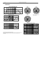
GEO S805 curves
ON AXIS RESPONSE (dB)
IMPEDANCE (Ohms)
10
64
0
32
−10
16
−20
−30
30
100
1k
10k
20k
On Axis response in dB. From dark to light: set up ‘wide range’, ‘CD12 stacked’ and ‘CD12
flown’.
8
30
100
1k
10k
20k
Impedance in Ohms
THD + N (%)
OFF AXIS RESPONSE Flange 80° (dB)
10
10%
0
1%
−10
−20
100
1k
10k
20k
0.1%
100
1k
10k
20k
Total harmonic distortion + noise in percentage. Level = 110dB @ 1m.
Off axis response in dB in the non-coupling plane flange 80°.
Dark to light: 0°, 10°, 20°, 30° and 40° off axis.
OFF AXIS RESPONSE Flange 120° (dB)
5000 Hz
10
0
2500Hz
30
330
0
30
330
60
0
60
300
300
90
270
−10
90
270
240
120
−20
100
240
120
1k
10k
210
150
20k
180
Off axis response in dB in the non-coupling plane flange 120°.
From dark to light: 0°, 15°, 30°, 45° and 60° off axis.
210
150
180
COVERAGE ANGLE (Degree)
Flange 80° (dark) and flange
120° (light) polar plot in the
non-coupling plane.
3dB/division.
200˚
10000 Hz
0
100˚
30
330
60
300
90
10˚
100
270
120
1k
10k
240
20k
Total coverage @-6dB in the coupling plane in degrees.
From dark to light: 1, 2 and 4 boxes.
150
210
180
Q & DI
COVERAGE ANGLE (Degree)
200˚
20
100
10
10
100˚
20˚
100
1k
10k
Total coverage @-6dB in the non-coupling plane in degrees:
flange 80° (dark) and flange 120 (light).
All measurements made with dedicated NX program.
Measurements conditions: far field, half space below 400Hz; anechoic above 400Hz.
Directivity Index and factor: computer synthesized from coverage. Coverage 1/3rd octave
band synthesized from FFT measurements.
0
100
1
1k
10k
Directivity Index in dB (Left hand side scale) and directivity factor (
Right hand side scale) for flange 120° (dark) and flange 80° (light).
20k
TECHNICAL SPECIFICATIONS
P.27
GEO S830
SYSTEM SPECIFICATIONS
GEO S830 with NX242 TDcontroller
Frequency Response [a]
67 Hz – 19 kHz ± 3 dB
Usable Range @-6dB [a]
60 Hz – 20 kHz
Sensitivity 1W @ 1m [b]
99 dB SPL Nominal -97 dB SPL Wideband
Peak SPL @ 1m [b]
125 to 128 dB Peak for a single cabinet. Configuration dependant when arrayed
Dispersion [c]
Directivity Index [c]
Coupling Plane: 30° for a single cabinet. Configuration dependant
Non-coupling plane: 120° (configurable to 80°).
DI = 12 Nominal (f > 1.5 kHz) for a single cabinet. Configuration dependant when arrayed.
Crossover Frequency
1.8 kHz Passive
Nominal Impedance
16 ohms
Recommended Amplifiers
1500 to 3000 Watts into 4 ohms / 4 cabinets per channel. Up to 6 cabinets per channel may be connected to large
amplifiers capable of operating into low impedance loads.
FEATURES
GEO S830
Components
Height x Width x Depth
LF: 1 x 8” (20cm) Neodymium Hi-flux 16 Ohm Driver
HF: 1 x 1” Throat Neodymium Driver on a Hyperboloid Reflective Wavesource
406 x 250 x 219 mm (16” x 9 7/8” x 5 5/8”) without flying hardware
Shape
30° Trapezoid
Weight
13 kg (28.7 lbs) with Tangent Array Assembly System; 10.5 kg (23 lbs) net
Connectors
2 x NL4MP SPEAKON 4 pole (In & Through)
Construction
Baltic Birch Ply finish with structured black coating.
Front Finish
Perforated Steel Grill
Flying points
Integral flying system. Intercabinet Angle Adjustments = 0.31 to 5° (logarithmic steps), 17.5° & 30°
SYSTEM OPERATION
Electronic Controller
HF Dispersion Configuration
Array Design
Sub-bass
The NX242 Digital TDcontroller presets are precisely matched to the GEO S8-Series cabinets and include
sophisticated protection systems. Using GEO S Series cabinets without a properly connected NX242 Digital
TDcontroller will result in poor sound quality and can damage components.
After quick release of the front grill from its fittings, the HF Waveguide can be configured for 80° or 120° dispersion
in the non-coupling plane.
S805 and S830 cabinets, having tangent waveguides, can be mixed in the same array.
Speaker Cables
The S830 can be used without the optional CD12 Hypercardiod Sub. In this case the NX242 can be used in
stereo. With the CD12 Hypercardiod Sub each Sub channel requires two NX242 outputs and the NX242 will
operate in mono.
The GEO S830 are wired 1- & 1+ on both Speakon connectors, 2- & 2+ are not connected.
Rigging System
See corresponding chapter of this manual.
302 mm
30°°
30
276 mm
[a] [b] [c] See measurement notes at the end of CD12 specifications
428 mm
Weight: 13 kg/28.7 lbs
P.28
TECHNICAL SPECIFICATIONS
GEO S830 curves
ON AXIS RESPONSE (dB)
IMPEDANCE (Ohms)
10
64
0
32
−10
16
−20
−30
30
100
1k
10k
8
20k
On Axis response in dB. From dark to light: set up ‘wide range’, ‘CD12 stacked’ and
‘CD12 flown’.
30
100
1k
10k
20k
Impedance in Ohms.
THD + N (%)
OFF AXIS RESPONSE Flange 80° (dB)
10
10%
0
1%
−10
−20
100
1k
10k
20k
0.1%
100
1k
10k
20k
Total harmonic distortion + noise in percentage. Level = 110dB @ 1m.
Off axis response in dB in the non-coupling plane flange 80°.
Dark to light: 0°, 10°, 20°, 30° and 40° off axis.
OFF AXIS RESPONSE Flange 120° (dB)
2500Hz
10
5000 Hz
0
30
0
60
0
30
330
90
330
60
300
270
300
90
270
−10
240
120
−20
100
1k
10k
20k
COVERAGE ANGLE (Degree)
210
150
180
Off axis response in dB in the non-coupling plane flange 120°.
From dark to light: 0°, 15°, 30°, 45° and 60° off axis.
240
120
210
150
180
10000 Hz
200˚
Flange 80° (dark) and flange 120° (light) polar
plot in the non-coupling plane. 3dB/division.
0
30
330
100˚
60
300
90
270
240
120
10˚
100
210
150
1k
10k
20k
180
Total coverage @-6dB in the coupling plane in degrees.
From dark to light: 1, 2 and 4 boxes.
Q & DI
COVERAGE ANGLE (Degree)
200˚
20
100
10
10
100˚
20˚
100
1k
10k
Total coverage @-6dB in the non-coupling plane in degrees: flange
80° (dark) and flange 120 (light).
All measurements made with dedicated NX program.
Measurements conditions: far field, half space below 400Hz; anechoic above 400Hz.
Directivity Index and factor: computer synthesized from coverage. Coverage 1/3rd octave
band synthesized from FFT measurements.
0
100
1
1k
10k
Directivity Index in dB (Left hand side scale) and directivity factor
(Right hand side scale) for flange 120° (dark) and flange 80° (light).
20k
TECHNICAL SPECIFICATIONS
P.29
GEO CD12
SYSTEM SPECIFICATIONS
CD12 with NX242 TDcontroller
Frequency Response [a]
42 Hz – 200 Hz ± 3 dB
Usable Range @-6dB [a]
39 Hz – 250 Hz
Sensitivity 1W @ 1m [b]
102 dB SPL Nominal
Peak SPL @ 1m [b]
131 to 134 dB Peak (500 to 1200W RMS Amp)
Dispersion [c]
Directivity Index [c]
Hypercardiod pattern 120° x 120° over the entire useable bandwidth. Directivity Control is achieved through
DSP algorithms in the NX242 Digital TDcontroller (two channels of the NX242 are used for the process).
Q = 3.773 DI = 5.7 dB over the entire useable bandwidth.
Crossover Frequency
150 Hz Active through NX242 Digital TDcontroller
Nominal Impedance
2x 6 Ohms
Recommended Amplifiers
2 amplifier channels are required for Hypercardiod operation, each rated at 1500 to 3000 Watts into 4 ohms
per channel. Up to 2 complete CD12s per channel may be connected to a two channel amplifier.
FEATURES
GEO CD12
Components
2 x 12” (30cm) Long Excursion Neodymium 6 Ohm Driver
Height x Width x Depth
400 x 600 x 754 mm (15 3/4” x 23 5/8” x 29 11/16”)
Shape
Rectangular
Weight: Net
35 kg (77 lbs)
Connectors
2 x NL4MP SPEAKON 4 pole (In & Through)
Construction
Baltic Birch Ply finish with structured black coating. Dark grey carpet finish also available.
Flying points
Integral flying system.
SYSTEM OPERATION
Electronic Controller
Sub-bass
Speaker Cables
Rigging System
The NX242 Digital TDcontroller presets are precisely matched to the GEO S8-Series cabinets and include
sophisticated protection systems. Using GEO S8-Series cabinets without a properly connected NX242 Digital
TDcontroller will result in poor sound quality and can damage components.
The GEO S805 & S830 can be used without the optional CD12 Hypercardiod Sub. In this case the NX242
can be used in stereo. With the CD12 Hypercardiod Sub each Sub channel requires two NX242 outputs and
the NX242 will operate in mono.
The front loudspeaker of the CD12 is wired 2+ & 2- while the rear loudspeaker is wired 1- & 1+. The CD12
must use separate cables to the GEO S805/S830.
See corresponding chapter of this manual.
As part of a policy of continual improvement, NEXO reserves the right to change specifications without notice.
[a]
Response Curves and Data: Anechoic Far Field above 200 Hz, Half-space Anechoic below 200 Hz.
Usable Range Data: Frequency Response Capability with TD crossover slopes removed.
[b]
Sensitivity & Peak SPL: will depend on spectral distribution. Measured with band limited Pink Noise.
Refers to the specified +/- 3 dB range. Data are for Speaker + Processor + recommended amplifier combinations.
[c]
Directivity Curves and Data: 1/3 octave smoothed frequency response, normalized to On-Axis response. Data obtained by computer processing of
off-axis response curves.
400 mm
600 mm
754 mm
Weight : 35 kg/77 lbs
P.30
TECHNICAL SPECIFICATIONS
CD12 curves
ONAXIS RESPONSE (dB)
63 Hz
40 Hz
10
0
0
330
30
300
60
330
30
300
60
0
90
270
90
270
10
120
20
150
30
100
120
240
200
240
150
210
180
On-axis response in dB. Maximum Bandwidth. Actual bandwidth depends from NX242 settings
IMPEDANCE (Ohms)
Horizontal (dark) and vertical (light)
polar plot. 3dB/division.
100 Hz
32
210
180
0
330
30
16
300
60
8
90
270
4
30
100
200
120
240
Impedance in Ohms.
150
210
180
Q & DI
10
COVERAGE ANGLE (Degree)
10
180
120
5
60
0
1
30
100
200
0
Directivity Index in dB (Left hand side scale) and directivity factor (Right hand side scale).
−60
−120
All measurements made with dedicated NX242 program.
Measurements conditions: far field, half space below 400Hz; anechoic above 400Hz. Directivity Index and
factor: computer synthesized from coverage. Coverage 1/3rd octave band synthesized from FFT
measurements.
−180
30
100
Horizontal (dark) and vertical (light) coverage @-6dB.
200
USER’S NOTES
USER’S NOTES
P.31
France
Nexo S.A.
154 allée des Erables
ZAC des PARIS NORD II B.P. 50107
F-95950 Roissy CDG Cedex
Tel: +33 1 48 63 19 14
Fax: +33 1 48 63 24 61
E-mail: [email protected]
www.nexo-sa.com