1
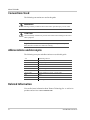
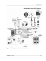
Smart choice for power
Installation Guide
Inverter Stacking
Control Series
(ISC-S) Cable
www.xantrex.com
Inverter Stacking Control Series (ISC-S)
Cable
Installation Guide
About Xantrex
Xantrex Technology Inc. is a world-leading supplier of advanced power electronics and controls with products from
50 watt mobile units to one MW utility-scale systems for wind, solar, batteries, fuel cells, microturbines, and backup
power applications in both grid-connected and stand-alone systems. Xantrex products include inverters, battery
chargers, programmable power supplies, and variable speed drives that convert, supply, control, clean, and distribute
electrical power.
Trademarks
Inverter Stacking Control – Series Cable is a trademark of Xantrex International. Xantrex is a registered trademark of
Xantrex International.
Other trademarks, registered trademarks, and product names are the property of their respective owners and are used
herein for identification purposes only.
Notice of Copyright
Inverter Stacking Control Series (ISC-S) Cable Installation Guide© January 2004 Xantrex International. All rights
reserved.
Disclaimer
UNLESS SPECIFICALLY AGREED TO IN WRITING, XANTREX TECHNOLOGY INC. (“XANTREX”)
(a) MAKES NO WARRANTY AS TO THE ACCURACY, SUFFICIENCY OR SUITABILITY OF ANY
TECHNICAL OR OTHER INFORMATION PROVIDED IN ITS MANUALS OR OTHER DOCUMENTATION.
(b) ASSUMES NO RESPONSIBILITY OR LIABILITY FOR LOSS OR DAMAGE, WHETHER DIRECT,
INDIRECT, CONSEQUENTIAL OR INCIDENTAL, WHICH MIGHT ARISE OUT OF THE USE OF SUCH
INFORMATION. THE USE OF ANY SUCH INFORMATION WILL BE ENTIRELY AT THE USER’S RISK.
Date and Revision
January 2004 Rev A
Part Number
975-0059-01-01 Rev A
Contact Information
Telephone: 1 800 670 0707 (toll free North America)
1 360 925 5097 (direct)
Fax:
1 800 994 7828 (toll free North America)
1 360 925 5143 (direct)
Email:
[email protected]
Web:
www.xantrex.com
About This Guide
Purpose
The purpose of this Installation Guide is to provide explanations and procedures
for installing the Inverter Stacking Control – Series Cable and provides
information regarding stacking two identical Sine Wave Plus inverters.
Scope
The Guide provides safety guidelines, detailed planning and setup information for
stacking inverters, and procedures for installing the ISC-S cable.
Audience
The Guide is intended for anyone who needs to install series-stacked, Sine Wave
Plus inverters using the Inverter Stacking Control – Series Cable. Installers should
be certified technicians or electricians.
Organization
This Guide is organized into three chapters.
Chapter 1, “Introduction” provides information on stacking of Sine Wave Plus
inverters.
Chapter 2, “Installation” provides information on installing the DC wiring, AC
Wiring, and the ISC-S for Sine Wave Plus inverters.
Chapter 3, “Operation”contains information on startup and functional testing
procedures for series-stacked Sine Wave Plus inverters.
Warranty and Product Information is provided at the end of the Guide.
975-0059-01-01 Rev A
iii
About This Guide
Conventions Used
The following conventions are used in this guide.
WARNING
Warnings identify conditions that could result in personal injury or loss of life.
CAUTION
Cautions identify conditions or practices that could result in damage to the unit or
other equipment.
Important: These notes describe things which are important for you to
know, but not as serious as a caution or warning.
Abbreviations and Acronyms
The following acronyms and abbreviations are used in this guide:
AC
ASC
BTS
DC
DCCB
DVM
GSM
ISC-S cable
Hz
RMA
Vac
Alternating Current
Authorized Service Center
Battery Temperature Sensor
Direct Current
DC Conduit Box
Digital Voltage Meter
Generator Start Module
Inverter Stacking Control – Series Cable
Hertz
Return Material Authorization
AC Voltage
Related Information
You can find more information about Xantrex Technology Inc. as well as its
products and services at www.xantrex.com
iv
975-0059-01-01 Rev A
Important Safety Instructions
WARNING
This chapter contains important safety and operating instructions. Read and keep this
Installation Guide for future reference.
1. Before installing and using the ISC-S cable, read all instructions and
cautionary information in this guide.
2. Do not expose the ISC-S cable to rain, snow, spray, or water.
3. Use only attachments recommended or sold by the manufacturer. Doing
otherwise may result in a risk of fire, electric shock, or injury to persons.
4. Do not operate the ISC-S cable if it has been damaged in any way. If the ISCS cable is damaged, see the Warranty section.
5. Do not disassemble the ISC-S cable. It contains no user-serviceable parts. See
Warranty for instructions on obtaining service. Attempting to service the ISCS cable yourself will void your wawrranty.
6. To reduce the risk of electrical shock, disconnect both AC and DC power
from the inverters before attempting any maintenance or cleaning or working
on any circuits connected to the ISC-S cable. Turning off the inverters will not
reduce this risk.
975-0059-01-01 Rev A
v
vi
Contents
Important Safety Instructions - - - - - - - - - - - - - - - - - - - - - - - - - - - - - - - - - - - - - - - - - - - -v
1
Introduction
Stacking Inverters - - - - - - - - - - - - - - - - - - - - - - - - - - - - - - - - - - - - - - - - - - - - - - - - - - - - - - 1–2
The ISC-S Cable - - - - - - - - - - - - - - - - - - - - - - - - - - - - - - - - - - - - - - - - - - - - - - - - - - - - - - - 1–5
2
Installation
DC Wiring - - - - - - - - - - - - - - - - - - - - - - - - - - - - - - - - - - - - - - - - - - - - - - - - - - - - - - - - - - - 2–2
Battery Requirements for Series-stacked Inverters - - - - - - - - - - - - - - - - - - - - - - - - - - - - - - 2–2
Battery-Bank Configuration for Series-stacked Inverters - - - - - - - - - - - - - - - - - - - - - - - - - 2–2
Grounding Series-stacked Inverters - - - - - - - - - - - - - - - - - - - - - - - - - - - - - - - - - - - - - - - - 2–3
Connecting the Battery Bank to the Inverters - - - - - - - - - - - - - - - - - - - - - - - - - - - - - - - - - 2–4
AC Wiring - General - - - - - - - - - - - - - - - - - - - - - - - - - - - - - - - - - - - - - - - - - - - - - - - - - - - - 2–6
Inverter AC Distribution Panel (Sub-Panel) Wiring (if used) - - - - - - - - - - - - - - - - - - - - - - - 2–6
Neutral Bonding - - - - - - - - - - - - - - - - - - - - - - - - - - - - - - - - - - - - - - - - - - - - - - - - - - - - 2–7
Grounding - - - - - - - - - - - - - - - - - - - - - - - - - - - - - - - - - - - - - - - - - - - - - - - - - - - - - - - - - 2–7
AC Wiring - Specific - - - - - - - - - - - - - - - - - - - - - - - - - - - - - - - - - - - - - - - - - - - - - - - - - - - - 2–8
Off-Grid AC Wiring for Sine Wave Plus Inverters - - - - - - - - - - - - - - - - - - - - - - - - - - - - - - 2–8
On-Grid AC Wiring for Sine Wave Plus Inverters - - - - - - - - - - - - - - - - - - - - - - - - - - - - - 2–10
Generator AC Wiring to Series-stacked Inverters - - - - - - - - - - - - - - - - - - - - - - - - - - - - - 2–12
Wiring for a 240 Vac-Only Input Source - - - - - - - - - - - - - - - - - - - - - - - - - - - - - - - - - - - 2–14
Connecting the ISC-S Cable - - - - - - - - - - - - - - - - - - - - - - - - - - - - - - - - - - - - - - - - - - - - - - 2–16
3
Operation
Start-up and Testing- - - - - - - - - - - - - - - - - - - - - - - - - - - - - - - - - - - - - - - - - - - - - - - - - - - - - 3–2
Setting Changes - - - - - - - - - - - - - - - - - - - - - - - - - - - - - - - - - - - - - - - - - - - - - - - - - - - - - - - 3–4
Automatic and Manual Generator Control - - - - - - - - - - - - - - - - - - - - - - - - - - - - - - - - - - - 3–4
Bulk and Float Charging Parameters - - - - - - - - - - - - - - - - - - - - - - - - - - - - - - - - - - - - - - - 3–4
Equalize Charging - - - - - - - - - - - - - - - - - - - - - - - - - - - - - - - - - - - - - - - - - - - - - - - - - - - 3–4
Automatic Generator Equalize Charging - - - - - - - - - - - - - - - - - - - - - - - - - - - - - - - - - 3–5
Manual Equalize Charging - - - - - - - - - - - - - - - - - - - - - - - - - - - - - - - - - - - - - - - - - - - 3–5
Warranty and Return Information - - - - - - - - - - - - - - - - - - - - - - - - - - - - - - - - - - - - WA–1
Index - - - - - - - - - - - - - - - - - - - - - - - - - - - - - - - - - - - - - - - - - - - - - - - - - - - - - - - - - - - - - - - - IX–1
975-0059-01-01 Rev A
vii
viii
Figures
Figure 1-1
Figure 1-2
Figure 1-3
Figure 2-1
Figure 2-2
Figure 2-3
Figure 2-4
Figure 2-5
Figure 2-6
Figure 2-7
Figure 2-8
Figure 2-9
Figure 2-10
Figure 3-1
Off-Grid Applications with Series-Stacked Inverters- - - - - - - - - - - - - - - - - - - - - - - - - 1–3
On-Grid Applications with Series-stacked Inverters - - - - - - - - - - - - - - - - - - - - - - - - - 1–4
Inverter Stacking Control – Series Cable (ISC-S cable) - - - - - - - - - - - - - - - - - - - - - - - 1–5
Example of Battery Connections for Series-stacked Inverters (24 Vdc shown) - - - - - - - 2–2
DC Grounding of Series-stacked Inverters - - - - - - - - - - - - - - - - - - - - - - - - - - - - - - - 2–3
DC Connections for Dual Inverters, Series-stacked- - - - - - - - - - - - - - - - - - - - - - - - - - 2–5
AC Wiring for Series-stacked SW Plus Inverters Off Grid - - - - - - - - - - - - - - - - - - - - - 2–9
AC Wiring for Series-stacked SW Plus Inverters OnGrid - - - - - - - - - - - - - - - - - - - - 2–11
Generator Wiring to Series-stacked SW Plus Inverters - - - - - - - - - - - - - - - - - - - - - - 2–13
AC Wiring for a 240 Vac-Only Input Source - - - - - - - - - - - - - - - - - - - - - - - - - - - - - 2–15
The 25-pin D-connector on the ISC-S Cable - - - - - - - - - - - - - - - - - - - - - - - - - - - - - 2–16
Stacking Port Locations on SW Plus Inverters - - - - - - - - - - - - - - - - - - - - - - - - - - - - 2–16
The ISC-S Cable Connected to Dual Sine Wave Plus Inverters- - - - - - - - - - - - - - - - - 2–17
Testpoints for Confirming Voltages - - - - - - - - - - - - - - - - - - - - - - - - - - - - - - - - - - - - 3–3
975-0059-01-01 Rev A
ix
x
1
Introduction
Chapter 1, “Introduction” provides information on stacking of Sine
Wave Plus inverters.
The following topics are covered in this chapter.
For this topic:
See:
“Stacking Inverters”
page 1–2
“The ISC-S Cable”
page 1–5
Introduction
Stacking Inverters
Two identical, series-stacked, inverters can be connected together for the
following purposes.
•
•
The voltage output of a single inverter is insufficient to power the 240 Vac
loads attached to the system;
Multi-wire branch circuits exists in the current structure. Please see Appendix
F, “Multi-wire Branch Circuit Wiring”, in the Sine Wave Plus Owner’s
Manual for additional information.
Important: Inverter types and models must be identical for stacking
configurations. In other words, you can use two SW Plus 2548 inverters, or two
SW Plus 4048 inverters. You cannot stack a SW Plus 2548 with a SW Plus 4048.
Different types of inverters cannot be intermixed in a stacking configuration.
Models with 230 Vac, 50 Hz, output cannot be series-stacked.
Stacking inverters in a “series” configuration can double the output voltage at the
same current level as an individual inverter.
Series-stacking connects the neutral outputs of each inverter together and enables
the inverters to synchronize their hot outputs to be 180 degrees out-of-phase with
each other. This maintains the wattage output at the rated level, but doubles the
voltage output available, thereby allowing 240 Vac loads to be supported by the
system.
Example: Two series-stacked, Sine Wave Plus 4024 Vac inverters can run both
120 Vac and 240 Vac loads at 33 amps continuous output.
Stacking inverters in a series configuration requires the use of the Inverter
Stacking Control-Series (ISC-S) Cable.
1–2
975-0059-01-01 Rev A
Stacking Inverters
Figure 1-1 Off-Grid Applications with Series-Stacked Inverters
975-0059-01-01 Rev A
1–3
Introduction
Figure 1-2 On-Grid Applications with Series-stacked Inverters
1–4
975-0059-01-01 Rev A
The ISC-S Cable
The ISC-S Cable
Required accessory
cable
Stacking two identical inverters requires the use of the Inverter Stacking Control –
Series Cable (ISC-S cable). The ISC-S cable is a special cable specifically
designed for series-stacking two identical inverters. It consists of one 36-inch
stacking control cable with two 25-pin D connectors. It connects to the “Stacking
Ports” on the respective inverters and allows the AC output of two (identical)
inverters to provide both 120 and 240 Vac, 60 Hz.
CAUTION: Damage to Equipment
Do not use a standard computer cable in place of the ISC-S cable cable. This ISCS cable is custom made for Xantrex to allow series-stacking with the SW Plus
Inverter/charger. Look for the label as shown in Figure 1-3 to properly identify the
cable.
Use of any other cable may damage your inverters and will not be covered by
Warranty/ Repair.
Xantrex ISC-S Cable
CAUTION: This cable is designed
for series stacking of the SW,
SW Plus, or PS inverters only.
Use of any other cable may damage
your inverter and void it’s warranty.
Figure 1-3 Inverter Stacking Control – Series Cable (ISC-S cable)
975-0059-01-01 Rev A
1–5
What it
does
The ISC-S cable provides communication between the two stacked inverters for two
purposes.
•
•
What it
does not do
1–6
It provides synchronization information for inverting and charging.
It provides a method for one inverter detecting an error condition to send a shutdown command to the other inverter, to prevent a 240Vac load from only receiving
one leg of power.
The ISC-S cable does not allow programming or access to the display from one inverter
to the other. If there are changes to the default setting necessary, each inverter must be
programmed separately. This includes selecting “On” in the “On/Off” menu.
2
Installation
Chapter 2, “Installation” provides information on installing the
DC wiring, AC Wiring, and the ISC-S for Sine Wave Plus inverters.
The following topics are covered in this chapter.
For this topic:
See:
“DC Wiring”
page 2–2
“AC Wiring - General”
page 2–6
“AC Wiring - Specific”
page 2–8
“Connecting the ISC-S Cable”
page 2–16
Installation
DC Wiring
The success of series-stacked, inverter systems is dependent on the quality and
maintenance of the DC connections. Stacked inverter sets are far less forgiving to
long, undersized, uneven, and/or poor connections than are single inverters.
Battery Requirements for Series-stacked Inverters
When inverters are “stacked” they must operate from a common battery bank. In
other words, the DC negative of one inverter must be common with the second
inverter and likewise for the DC positive.
For example:
If you have eight 6-volt batteries in a 24-volt configuration, they would be
arranged in two rows of four batteries (see Appendix C of the Sine Wave Plus
Owner’s Manual for diagrams of various arrangements). The negative ends of
the two “strings” of batteries must be jumpered together to become common
with each other. Likewise, the positive ends of the two “strings” must also be
jumpered together so that they are also common with each other.
Battery-Bank Configuration for Series-stacked Inverters
When using inverters in a stacked configuration, the same battery bank must be
used for both inverters. To ensure even charging of the batteries, each inverter
must be connected to both strings (i.e., positive cable to string two, and negative
cable to string one for inverter 1, and positive cable to string one and negative
cable to string two for inverter 2) as shown in Figure 2-1. In other words, a
separate positive (+) and negative (–) cable pair is required for each inverter in the
series-stacked configuration. This means there will be four battery cables from the
stacked inverters to the battery bank.
Refer to the Owner’s Manual for the Sine Wave Plus to determine the correct size
and length of cable required.
DC conduit for
L1 Inverter
DC conduit for
L2 Inverter
–
+
–
12 Volt
Battery
200 Ah
Series-strings
wired in Parallel
24 Vdc/400 Ah
–
+
12 Volt
Battery
200 Ah
12 Volt
Battery
200 Ah
–
+
Series String 1
24 Vdc/200 Ah
+
Series String 2
24 Vdc/200 Ah
12 Volt
Battery
200 Ah
Figure 2-1 Example of Battery Connections for Series-stacked Inverters
(24 Vdc shown)
2–2
975-0059-01-01 Rev A
DC Wiring
Grounding Series-stacked Inverters
To ground series-stacked inverters:
1. Connect the ground bond in the DC disconnect between the inverters and the
batteries to the primary grounding electrode, in accordance with local and
national electrical codes.
2. Connect an appropriately sized ground wire from the chassis bonding ground
lug on the L1 inverter DC end to the ground bond inside the DC disconnect.
3. Connect a second appropriately sized ground wire from the chassis bonding
ground lug on the L2 inverter DC end to a different terminal in the ground
bond inside the DC disconnect.
–
xantrex
I nver t er Cont r ol M odul e
+
01A Inverter
OFF SRCH ON CHG
INV
GEN
ONO
/ FF
ME N U
xantrex
G R IDT IE
IN V ER T
ME N U
HE A D N
I GS
S i ne Wave P l us I nverter/ Charger
ME N U
AC1
BUL K
E RROR
AC2
F L OAT
ST AT US
SET
P O IN T S
IT E M S
C o n tr a s t
R e s e tD e fa u lts
L1 Inverter
Chassis Bonding
Ground Lug
–
xantrex
I nver t er Cont r ol M odule
+
01A Inverter
OFF SRCH ON CHG
INV
GEN
O N /O F F
ME N U
xantrex
S i ne Wave P l us Inverter/ Charger
G R IDT IE
IN V ER T
ME N U
HEADN
I GS
ME N U
IT E M S
AC1
BUL K
AC2
F L OAT S T AT US
DC
DISCONNECT
E RROR
SET
P O IN T S
C o n rt a s t
R e s e tD e fa u lts
SHUNT &
NEGATIVE BUS
L2 Inverter
Chassis Bonding
Ground Lug
ON
ON
ON
OFF
OFF
OFF
GROUND
To primary
Earth/ground
connections
Figure 2-2 DC Grounding of Series-stacked Inverters
975-0059-01-01 Rev A
2–3
Installation
Connecting the Battery Bank to the Inverters
The following instructions are illustrated in Figure 2-3.
To connect the battery (or battery bank) to the inverters:
1. Connect POSITIVE cables:
a) one cable from the battery POSITIVE terminal to a circuit breaker in the
DC disconnect (torque to manufacturer’s recommendations). The DC
disconnect should be located as close to the batteries as possible.
b) a second cable from the same battery POSITIVE terminal to another
circuit breaker in the DC disconnect.
c) a third cable from the first circuit breaker in the DC disconnect to the
L2 inverter POSITIVE (+) terminal.
d) a fourth cable from the second DC disconnect to the L1 inverter
POSITIVE (+) terminal.
2. Connect NEGATIVE cables:
a) one cable from the same battery NEGATIVE terminal (torque to
manufacturer’s recommendations) to the ground bond in the DC
disconnect.
b) a second cable from the same battery NEGATIVE terminal (torque to
manufacturer’s recommendations) to the ground bond in the DC disconnect.
c) a third cable from the ground bond in the DC disconnect to the L2 inverter
NEGATIVE (–) terminal.
d) a fourth cable from the ground bond in the DC disconnect to the
L1 inverter NEGATIVE (–) terminal.
3. Ensure the correct polarity of the cables with a DC voltmeter (DVM).
4. Use an insulated 1/2 inch wrench or socket to tighten the 5/16 SAE nuts to
10-15 foot/lb for each inverter input terminal.
5. After tightening the connections on the batteries, apply antioxidant paste to
the battery terminals, if desired. Do not apply antioxidant paste to the inverter
terminals.
6. Install the battery terminal covers (if used)—red for positive, black for
negative—over the inverter DC terminals and secure with the screws and
washers provided.
2–4
975-0059-01-01 Rev A
DC Wiring
–
xantrex
I nverter Contr ol M odul e
+
01A Inverter
OFF SRCH ON CHG
INV
GEN
ON /O F F
xantrex
ME N U
G R ID T IE
IN V E R T
ME N U
HE A DN
I GS
S ine Wave P l us I nverter/ Charger
ME N U
IT E M S
AC 1
BU L K
E R R OR
AC 2
F L OA T
S T A T US
SE T
P OIN T S
C o n tr a s t
R ese D
t e fa u lts
L1 Inverter
Chassis Bonding
Ground Lug
2d
–
xantrex
I nver ter Control Modul e
+
01A Inverter
OFF SRCH ON CHG
INV
GEN
O N /O F F
ME N U
xantrex
S i ne Wave P l us I nve rter/ C harger
ME N U
H E A DN
I G S
ME N U
IT E MS
GR D
I TE
I
A C1
BU L K
IN V E R T
A C2
F L OA T S T A T U S
2c
DC
DISCONNECT
E R R OR
SE T
P OIN T S
C o n tr a s t
SHUNT &
NEGATIVE BUS
R e s e tD e fa u lts
L2 Inverter
1d
1c
Chassis Bonding
Ground Lug
ON
ON
Neutral-to-Ground
Bond
OFF
OFF
GROUND
1b
1a
2b
2a
DC Conduit for
L1 Inverter
DC Conduit
L2 Inverter
To primary
Earth/ground
connections
–
+
–
12 Volt
Battery
200 Ah
Series-strings
wired in Parallel
24 Vdc/400 Ah
12 Volt
Battery
200 Ah
+
Series String 1
24 Vdc/200 Ah
Series String 2
–
+
12 Volt
Battery
200 Ah
–
+
24 Vdc/200 Ah
12 Volt
Battery
200 Ah
Figure 2-3 DC Connections for Dual Inverters, Series-stacked
975-0059-01-01 Rev A
2–5
Installation
AC Wiring - General
Be sure to use the recommended wire and disconnect size as recommended in the
Owner’s Manual for the Sine Wave Plus Inverter.
WARNING
Before connecting any AC wiring, ensure that there is no DC energy accessible by the
inverter by opening the DC disconnect switch(es).
Inverter AC Distribution Panel (Sub-Panel) Wiring (if used)
An Inverter AC Distribution Panel (referred to here as the inverter panel) and AC
conduit must be installed before AC output wiring is connected to the dual
inverters. The inverter panel is a sub-panel to the main utility panel.
Install the Inverter AC Distribution Panel and conduit as follows:
1. Determine the location for the Inverter AC Distribution Panel (i.e., the
sub-panel) and install it according to the manufacturer’s directions.
2. Install an AC conduit to the inverter panel and the inverter.
3. Determine which circuits the inverter will power and install the appropriate
circuit breakers into the inverter panel.
4. For On-Grid systems, remove wires for circuits to be backed up from the main
utility panel and install then in the new inverter (sub) panel.
5. Install a double pole 60-amp maximum (disconnect) main circuit breaker in
the inverter panel: one for each leg of the circuit for L1 and L2.
6. Verify that under no circumstances can utility power or generator power
energize the inverter panel directly while the inverter also energizes the
inverter panel.
WARNING: Shock Hazard
Verify that only one neutral/ground bond exists in the system. Having more than one
neutral to ground bond in a system may create a shock hazard and cause some sensitive
equipment to malfunction.
On-Grid systems always have a ground-to-neutral bond provided by the utility meter or
service entrance, therefore do not need a ground-to-neutral bond made in the inverter
panel. Remove it if present in the sub-panel.
2–6
975-0059-01-01 Rev A
AC Wiring - General
Neutral Bonding
The HOT output of each inverter provides 120 Vac to neutral. The voltage
between the HOT outputs from the L1 and L2 inverter is 240 Vac when the ISC-S
cable is used.
When using a series-stacked, inverter configuration, it is important to provide a
neutral bond between both inverters. Accomplish this bond by establishing an
inverter-to-inverter neutral bond.
Keep the neutral bonding jumper as short as possible to provide a better AC “zero
volt” reference for each inverter to measure AC voltages from, as well as saving
on wire. The neutral bond wire must be the same gauge as the other AC wires
attached to the inverter.
Grounding
Ensure all components are grounded properly for safety and for code-compliance.
WARNING: Hazardous Voltage
When stacking inverters, ensure the chassis of each inverter is connected to the same
common ground (i.e., in the utility or inverter panels); otherwise a hazardous voltage may
be present between the chasses.
975-0059-01-01 Rev A
2–7
Installation
AC Wiring - Specific
The following AC connections are specific to installing the Sine Wave Plus
Inverter/chargers in a series-stacked configuration for off-grid and on-grid
applications.
Off-Grid AC Wiring for Sine Wave Plus Inverters
The following steps are illustrated in Figure 2-4.
Grounding
To connect the AC wiring for an off-grid application using Sine Wave Plus
Inverters:
1. Connect GROUND (green) wires:
Neutral Bonds
a) from the primary earth/ground to the AC distribution panel,
b) from the L1 inverter AC ground bar to the inverter panel ground bar,
c) from the L2 inverter AC ground bar to the inverter panel ground bar.
2. Connect NEUTRAL (white) wires:
Inverter to AC
Distribution Panel
2–8
a) from the NEUTRAL bus in the inverter panel, to the ground bar in the
inverter panel, (Neutral-to-Ground Bond),
b) from the L1 inverter NEUTRAL OUT terminal, to the L2 inverter NEUTRAL
2 terminal. (Inverter-to-inverter neutral bond),
c) from the L2 inverter NEUTRAL OUT terminal to the inverter panel
NEUTRAL bus. (Common neutral bond in inverter panel).
3. Connect a HOT wire:
a) (black) from the L1 inverter AC HOT OUTPUT (120 Vac) to the inverter
panel L1 terminal,
b) (red) from the L2 inverter AC HOT O UTPUT (120 Vac) to the inverter
panel L2 terminal.
4. Torque all inverter terminal block connections to 25 inch-pounds.
975-0059-01-01 Rev A
AC Wiring - Specific
Sine Wave Plus
Inverter/Charger
LEGEND
GROUND
NEUTRAL
HOT L1
INV OUT
NEUTRAL OUT
NEUTRAL 2
NEUTRAL 1
AC1 GRID
AC
GROUND
BAR
(inside)
AC2 GEN
AC TERMINAL
BLOCK
HOT L2
(L1)
1b
3a
Sine Wave Plus
Inverter/Charger
3b
L1
INV OUT
NEUTRAL OUT
NEUTRAL 2
AC1 GRID
AC Distribution Panel
(Inverter Panel) 3a
120/240 Vac
NEUTRAL 1
AC TERMINAL
BLOCK
AC
GROUND
BAR
(inside)
AC2 GEN
2b
(L2)
1c
L2
NEUTRAL
2c
3b
2a
GROUND
To AC Loads
To AC Loads
1b
1c
1a
To primary
Earth/ground
connections
NEUTRAL/
GROUND BOND
Figure 2-4 AC Wiring for Series-stacked SW Plus Inverters Off Grid
975-0059-01-01 Rev A
2–9
Installation
On-Grid AC Wiring for Sine Wave Plus Inverters
Prepare the AC wiring as follows for an on-grid application using series-stacked,
Sine Wave Plus Inverter/chargers. The following steps are illustrated in
Figure 2-5.
Grounding
1. Connect GROUND (green) wires:
Neutral Bonds
a) from the primary earth/ground to the main utility panel,
b) from the main utility panel to the AC distribution panel (Sub-panel),
c) from the L1 inverter AC ground bar to the utility panel ground bar,
d) from the L2 inverter AC ground bar to the utility panel ground bar.
2. Connect NEUTRAL (white) wires:
Inverter to AC
Distribution Panel
Inverter to Utility
Panel
a) from the Neutral bus in the utility panel to the ground bar in the utility
panel. (Neutral-to-ground bond),1
b) from the L1 inverter NEUTRAL OUT terminal to the L2 inverter
NEUTRAL 2 terminal (Interter-to-inverter neutral bond),
c) from the L1 inverter NEUTRAL OUT terminal to the utility or utility panel
neutral bus (Common neutral bond in utility panel),
d) from the L2 inverter NEUTRAL O UT terminal to the AC distribution panel
neutral bus (Common neutral bond in sub-panel),
3. Connect HOT wires:
a) (black) from the L1 inverter AC HOT OUTPUT (120 Vac) to the inverter
panel L1 terminal.
b) (red) from the L2 inverter AC HOT O UTPUT (120 Vac) to the inverter
panel L2 terminal.
4. Connect HOT wires:
a) (black) from the utility panel HOT L1 terminal to the L1 inverter’s AC1
GRID terminal.
b) (red) from the utility panel HOT L2 terminal to the L2 inverter’s AC1
GRID terminal.
5. Torque all inverter terminal block connections to 25 inch-pounds.
1.This connection may already exist from the original installation of AC service to the
building.
2–10
975-0059-01-01 Rev A
AC Wiring - Specific
Main Utility Panel
LEGEND
120/240 Vac Panel
GROUND
L1
NEUTRAL
L2
HOT L1
NEUTRAL
HOT L2
Sine Wave Plus
Inverter/Charger
L1
2c
L2
AC TERMINAL
BLOCK
1b
1c
1d
To primary
Earth/ground
connections
INV OUT
AC
GROUND
BAR
(inside)
AC1 GRID
1a
2a
NEUTRAL OUT
GROUND
NEUTRAL 1
NEUTRAL 2
4b
AC2 GEN
4a
NEUTRAL/GROUND
BOND
3a
4a
2b
(L1)
Sine Wave Plus
Inverter/Charger
3a
L1
INV OUT
NEUTRAL OUT
NEUTRAL 1
NEUTRAL 2
120/240 Vac
AC
GROUND
BAR
(inside)
AC2 GEN
AC Distribution Panel
(Sub-panel)
AC1 GRID
AC TERMINAL
BLOCK
(L2)
3b
1d
L2
NEUTRAL
4b
3b
2d
To AC Loads
GROUND
To AC Loads
1b
Figure 2-5 AC Wiring for Series-stacked SW Plus Inverters OnGrid
975-0059-01-01 Rev A
2–11
Installation
Generator AC Wiring to Series-stacked Inverters
The following wiring diagrams show the AC wiring from an AC generator to the
inverters.
The following procedures are illustrated in Figure 2-6.
Important: Ensure that an inverter-to-inverter neutral bond is in place
before proceeding with this procedure.
With a generator
disconnect switch
To install the AC wiring from a generator with a (GDS):
1. Connect GROUND (green) wires:
a) from the generator GROUND to the generator disconnect switch GROUND
terminal,
b) from the generator disconnect switch GROUND to the AC Ground bar in
the utility panel*.
2. Connect NEUTRAL (white) wires:
a) from the generator NEUTRAL to the GDS N EUTRAL terminal,
b) from the generator disconnect switch NEUTRAL to the L1 INVERTER
NEUTRAL 2 terminal.
3. Connect HOT (L1- black) wires:
a) from the generator L1 GEN HOT OUT to the GDS L1 HOT terminal,
b) from the generator disconnect switch L1 HOT to the L1 INVERTER AC2
GEN terminal.
4. Connect HOT (L2 - red) wires:
a) from the generator L2 HOT OUT to the generator disconnect switch
L2 HOT terminal,
b) from the generator disconnect switch L2 HOT to the L2 INVERTER AC2
GEN terminal.
5. Torque all inverter terminal block connections to 25 inch-pounds.
Important: *If this is an off-grid installation, then all connections that would normally
go to the Main Utility Panel should be routed to the AD Distribution Panel instead.
2–12
975-0059-01-01 Rev A
AC Wiring - Specific
Main Utility
Panel
LEGEND
120/240 Vac Panel
GROUND
L1
NEUTRAL
L2
HOT L1
NEUTRAL
NEUTRAL/GROUND
BOND
HOT L2
Sine Wave Plus
Inverter/Charger
L1
L2
GROUND
To primary
Earth/ground
connections
INV OUT
NEUTRAL OUT
NEUTRAL 2
NEUTRAL 1
AC1 GRID
1b
AC2 GEN
AC TERMINAL
BLOCK
AC
GROUND
BAR
(inside)
(L1)
2b
3b
4b
Generator
Disconnect
Switch
(optional)
Generator
120/240 Vac
N
G
L1
L2
Sine Wave Plus
Inverter/Charger
1a 3a 4a 2a
GROUND
NEUTRAL
L1
L2
GEN HOT OUT
INV OUT
NEUTRAL OUT
NEUTRAL 2
NEUTRAL 1
AC2 GEN
AC
GROUND
BAR
(inside)
AC Distribution Panel
(Sub-panel)
AC1 GRID
AC TERMINAL
BLOCK
(L2)
120/240 Vac
L1
L2
NEUTRAL
To AC Loads
GROUND
To AC Loads
Figure 2-6 Generator Wiring to Series-stacked SW Plus Inverters
975-0059-01-01 Rev A
2–13
Installation
Wiring for a 240 Vac-Only Input Source
A 240 Vac source does not allow for the connection to the input of a 120 Vac
inverter as no neutral line is supplied from the utility or generator. In order to use
stacked inverters, a neutral line must be added by using a center-tapped
autotransformer (such as a T240) on the inverter’s input. This will create the
necessary neutral return line for the inverters, and half the voltage for each
inverter to 120 Vac. The output of the inverter supplies both 120 and 240 Vac to
the loads.
The ISC-S cable and autotransformer (capable of handling the system’s power
requirements) are required in this configuration..
To wire the inverters for a 240-Vac only input source:
1. Run GROUND wires (green):
a) from the AC Distribution Panel to the primary earth/ground connection.
b) from the generator ground to the AC Distribution Panel ground.
c) from the ground terminal in the Autotransformer to the AC Distribution
Panel.
d) from the AC Distribution Panel to the Ground bar in the L1 inverter.
e) from the AC Distribution Panel to the Ground bar in the L2 inverter.
2. Run NEUTRAL wires (white):
a) from the center-tapped neutral connection in the autotransformer to the
NEUTRAL 1 terminal in the L1 inverter.
b) from the center-tapped neutral connection in the autotransformer to the
NEUTRAL 1 terminal in the L2 inverter.
c) from the NEUTRAL OUT on the L1 inverter to the NEUTRAL 2
terminal on the L2 inverter.
d) from the Neutral OUT on the L2 inverter to the Neutral terminal in the
AC Distribution Panel.
3. Run HOT wires:
a) (black) from the L1 Output in the generator to the L1 terminal in the
Autotransformer.
b) (black) from the L1 output terminal in the Autotransformer to the
AC2 GEN terminal in the L1 inverter.
c) (black) from the INV OUT terminal in the L1 inverter to the L1 input
terminal in the AC Distribution Panel.
d) (red) from the L2 Output in the generator to the L2 terminal in the
Autotransformer.
e) (red) from the L2 output terminal in the Autotransformer to the AC2 GEN
terminal in the L2 inverter.
f) (red) from the INV OUT terminal in the L2 inverter to the L2 input
terminal in the AC Distribution Panel.
4. Torque all inverter terminal block connections to 25 inch-pounds.
2–14
975-0059-01-01 Rev A
AC Wiring - Specific
LEGEND
Sine Wave Plus
Inverter/Charger
GROUND
NEUTRAL
HOT L1
HOT L2
INV OUT
3b
GROUND
GEN HOT
OUT
(L1)
1d
L1
1b
NEUTRAL OUT
(with center-tapped neutral-out)
AC1 GRID
AC
GROUND
BAR
(inside)
NEUTRAL 1
NEUTRAL 2
Auto-transformer
AC2 GEN
AC TERMINAL
BLOCK
L1
3a
2a
Neutral
L2
3d
Generator
240 Vac - ONLY
3e
L2
Ground
2c
3c
1c
Sine Wave Plus
Inverter/Charger
2b
120/240 Vac
L2
(L2)
INV OUT
NEUTRAL OUT
NEUTRAL 1
NEUTRAL 2
AC2 GEN
3f
L1
AC TERMINAL
BLOCK
AC1 GRID
AC Distribution Panel
(Inverter Panel) 3c
AC
GROUND
BAR
(inside)
1e
NEUTRAL
3f
2d
GROUND
To AC Loads
To AC Loads
1d
1a
1c
NEUTRAL/GROUND
BOND
1b
To primary Earth/
ground connections
Figure 2-7 AC Wiring for a 240 Vac-Only Input Source
975-0059-01-01 Rev A
2–15
Installation
Connecting the ISC-S Cable
The ISC-S Cable connects to the Stacking Port on the AC end of the Sine Wave
Plus Inverter/charger. The Stacking Port is a 25-pin receptacle for the 25-pin
D-connector on the ISC-S Cable. Once the connector is in place, it is secured by
two screws on the sides of the connector.
Align the head of the connector
with the Stacking Port on the
inverter and insert into the port.
Gently tighten these two screws to
secure in place.
Figure 2-8 The 25-pin D-connector on the ISC-S Cable
Stacking Port
Figure 2-9 Stacking Port Locations on SW Plus Inverters
To connect the ISC-S cable:
1. Orient the 25-pin D-connector to align with the Stacking Port on the Inverter
and gently press the connector into the port. Use caution not to bend the pins
inside the connector head.
2. Tighten the screws on the connector to secure the cable to the port.
3. Connect the other end of the ISC-S cable to the second inverter’s Stacking
Port as instructed in step 1 and 2.
2–16
975-0059-01-01 Rev A
Connecting the ISC-S Cable
Connect one end of ISC-S
Cable to the Stacking Port
of the L1 inverter.
Connect the other end of
ISC-S Cable to the Stacking
Port of the L2 inverter.
Figure 2-10 The ISC-S Cable Connected to Dual Sine Wave Plus Inverters
CAUTION; Damage to Loads
Until the units are tested, do not connect any loads to the inverters. Proceed to the next
chapter for Start up and Functional Testing Procedures.
975-0059-01-01 Rev A
2–17
2–18
3
Operation
Chapter 3, “Operation”contains information on startup and functional
testing procedures for series-stacked Sine Wave Plus inverters.
The following topics are covered in this chapter.
For this topic:
See:
“Start-up and Testing”
page 3–2
“Setting Changes”
page 3–4
Operation
Start-up and Testing
Stacked inverters must operate together in order to provide the 120/240 Vac to the
loads. The ISC-S cable ensures the output from each inverter is 180 degrees
out-of-phase for operating 240 Vac loads.
To start up and test the inverters:
1. Ensure the circuit breakers on all AC sources (utility or generator, if any)
feeding the inverters are OFF.
2. Ensure the circuit breakers in the AC distribution panel (sub-panel) are OFF.
3. Switch ON both inverters. The inverters should be providing 120/240 Vac to
the AC distribution panel.
4. In the AC distribution panel, use an AC voltmeter and measure the voltage
between the L1 (HOT) terminal and the neutral bus. This voltage should be
120 Vac (± 3%). See Figure 3-1 for testpoint locations.
5. In the AC distribution panel, use an AC voltmeter and measure the voltage
between the L2 (HOT) terminal and the neutral bus. This voltage should be
120 Vac (± 3%). See Figure 3-1 for testpoint locations.
6. In the AC distribution panel, measure the voltage between the L1 (HOT) and
L2 (HOT) terminals. This voltage should be 240 Vac (± 3%). See Figure 3-1
for testpoint locations.
7. If all voltages/tests are correct,
a) switch on the circuit breakers in the AC distribution panel, and
b) switch on the generator or utility circuit breakers feeding the inverters.
8. Verify the inverters are charging the batteries and powering the AC
distribution panel.
9. Switch both inverters OFF and open the circuit breakers to ensure all AC and
DC power is turned OFF to the inverters.
10. Replace all covers and panels on the inverters and sub-panel.
11. The series-stacked inverter system is now tested and ready for use.
If the inverters are not operating properly, please refer to the Sine Wave Plus
Operator’s Manual for setup and troubleshooting information.
3–2
975-0059-01-01 Rev A
Start-up and Testing
LEGEND
GROUND
NEUTRAL
HOT L1
HOT L2
AC Distribution Panel
(Sub-panel)
To L1 Inverter
120/240 Vac
6
L1
L2
NEUTRAL
4
5
To L2 Inverter
To L2 Inverter
To 120 Vac
Loads
GROUND
To 240 Vac
Loads
To Main Utility
Panel Ground
Figure 3-1 Testpoints for Confirming Voltages
975-0059-01-01 Rev A
3–3
Operation
Setting Changes
When operating a Sine Wave Plus in a series-stacked configuration, the following
settings must be changed for proper operation.
See the Owner’s Manual for the Sine Wave Plus for detailed instructions on
accessing and changing the settings using the Inverter Control Module (ICM) on
the inverter.
Automatic and Manual Generator Control
When multiple inverters are used with a generator, the inverter connected to the
generator via the Generator Start Module (GSM) is designated as the “generator
controlling” inverter. The most efficient battery charging is achieved by setting
the charging parameters of each inverter slightly differently.
Bulk and Float Charging Parameters
Change the Bulk and Float Charging settings as follows:
• Set the 12B BULK VOLTS DC to the same setting on both inverters.
• Set the 12C FLOAT VOLTS DC to the same setting on both inverters.
• On the non-generator-controlling inverter (the inverter not connected to a
GSM), set the charging time for a shorter period than on the generator
controlling inverter. This is accomplished by setting the 12F BULK DONE
AMPS to a higher setting. If the 12F BULK DONE AMPS is set to zero (0), then
the 12H MAX BULK/EQ Timer h:m should be set to a shorter time period on
the non-generator-controlling inverter.
Equalize Charging
Change the Equalize Charging settings as follows:
• Set both inverters to the same 12D EQUALIZE VOLTS DC setting.
• Set the 12G EQ VDC DONE TIMER H:M on the “generator controlling” inverter
to a shorter equalize time.
To start an Equalize charge (manually or automatically), set both inverters to EQ
by scrolling to 01B EQ CHARGE ON/O FF and selecting ON.
During the equalize charge, the Bulk LED will slowly flash on each inverter,
indicating the EQ selection has been enabled.
3–4
975-0059-01-01 Rev A
Setting Changes
Automatic Generator Equalize Charging
If the inverters are set to automatically charge the batteries using the generator, the
equalize process will begin during the next, automatically started, generator run
period. When the equalizing process has completed, the generator automatically
stops and the cursor returns to the OFF position in the 01B EQ CHARGE menu
item on the generator-controlling inverter. The non-generator-controlling inverter
must be set from EQ to OFF from the 01B EQ CHARGE menu item or it will start
another equalize charge the next time the generator is started.
Manual Equalize Charging
If the batteries were equalized using a manually started generator or from the
utility grid, the FLOAT LED illuminates, indicating the equalization process is
complete. Set the cursor to OFF on both inverters under the 01B EQ CHARGE
menu item when the equalization process is complete.
Important: If using multiple battery temperature sensors (BTS) ensure they are all
connected to the same location (battery).
975-0059-01-01 Rev A
3–5
3–6
Warranty and Return Information
Warranty
What does this warranty cover? This Limited Warranty is provided by Xantrex Technology, Inc. ("Xantrex")
and covers defects in workmanship and materials in your Inverter Stacking Control – Series Cable. This warranty
period lasts for two (2) years from the date of purchase at the point of sale to you, the original end user customer. You
require proof of purchase to make warranty claims.
This Limited Warranty is transferable to subsequent owners but only for the unexpired portion of the Warranty
Period.Subsequent owners also require proof of purchase.
What will Xantrex do?
Xantrex will, at its option, repair or replace the defective product free of charge, provided that you notify Xantrex of
the product defect within the Warranty Period, and provided that Xantrex through inspection establishes the existence
of such a defect and that it is covered by this Limited Warranty.
Xantrex will, at its option, use new and/or reconditioned parts in performing warranty repair and building
replacement products. Xantrex reserves the right to use parts or products of original or improved design in the repair
or replacement. If Xantrex repairs or replaces a product, its warranty continues for the remaining portion of the
original Warranty Period or 90 days from the date of the return shipment to the customer, whichever is greater. All
replaced products and all parts removed from repaired products become the property of Xantrex.
Xantrex covers both parts and labor necessary to repair the product, and return shipment to the customer via a
Xantrex-selected non-expedited surface freight within the contiguous United States and Canada. Alaska and Hawaii
are excluded. Contact Xantrex Customer Service for details on freight policy for return shipments outside of the
contiguous United States and Canada.
How do you get service? If your product requires troubleshooting or warranty service, contact your merchant. If
you are unable to contact your merchant, or the merchant is unable to provide service, contact Xantrex directly at:
Telephone: 1 800 670 0707 (toll free North America)
1 360 925 5097 (direct)
Fax:
1 800 994 7828 (toll free North America)
1 360 925 5143 (direct)
Email:
[email protected]
Direct returns may be performed according to the Xantrex Return Material Authorization Policy described in your
product manual. For some products, Xantrex maintains a network of regional Authorized Service Centers. Call
Xantrex or check our website to see if your product can be repaired at one of these facilities.
What proof of purchase is required? In any warranty claim, dated proof of purchase must accompany the
product and the product must not have been disassembled or modified without prior written authorization by Xantrex.
Proof of purchase may be in any one of the following forms:
• The dated purchase receipt from the original purchase of the product at point of sale to the end user, or
• The dated dealer invoice or purchase receipt showing original equipment manufacturer (OEM) status, or
• The dated invoice or purchase receipt showing the product exchanged under warranty
975-0059-01-01 Rev A
WA–1
Warranty and Return
What does this warranty not cover? This Limited Warranty does not cover normal wear and tear of the
product or costs related to the removal, installation, or troubleshooting of the customer's electrical systems. This
warranty does not apply to and Xantrex will not be responsible for any defect in or damage to:
a) the product if it has been misused, neglected, improperly installed, physically damaged or altered, either internally or externally, or damaged from improper use or use in an unsuitable environment;
b) the product if it has been subjected to fire, water, generalized corrosion, biological infestations, or input voltage
that creates operating conditions beyond the maximum or minimum limits listed in the Xantrex product specifications including high input voltage from generators and lightning strikes;
c) the product if repairs have been done to it other than by Xantrex or its authorized service centers (hereafter
"ASCs");
d) the product if it is used as a component part of a product expressly warranted by another manufacturer;
e) the product if its original identification (trade-mark, serial number) markings have been defaced, altered, or
removed.
Disclaimer
Product
THIS LIMITED WARRANTY IS THE SOLE AND EXCLUSIVE WARRANTY PROVIDED BY XANTREX IN CONNECTION WITH YOUR
XANTREX PRODUCT AND IS, WHERE PERMITTED BY LAW, IN LIEU OF ALL OTHER WARRANTIES, CONDITIONS,
GUARANTEES, REPRESENTATIONS, OBLIGATIONS AND LIABILITIES, EXPRESS OR IMPLIED, STATUTORY OR OTHERWISE IN
CONNECTION WITH THE PRODUCT, HOWEVER ARISING (WHETHER BY CONTRACT, TORT, NEGLIGENCE, PRINCIPLES OF
MANUFACTURER'S LIABILITY, OPERATION OF LAW, CONDUCT, STATEMENT OR OTHERWISE), INCLUDING WITHOUT
RESTRICTION ANY IMPLIED WARRANTY OR CONDITION OF QUALITY, MERCHANTABILITY OR FITNESS FOR A PARTICULAR
PURPOSE. ANY IMPLIED WARRANTY OF MERCHANTABILITY OR FITNESS FOR A PARTICULAR PURPOSE TO THE EXTENT
REQUIRED UNDER APPLICABLE LAW TO APPLY TO THE PRODUCT SHALL BE LIMITED IN DURATION TO THE PERIOD
STIPULATED UNDER THIS LIMITED WARRANTY.
IN NO EVENT WILL XANTREX BE LIABLE FOR ANY SPECIAL, DIRECT, INDIRECT, INCIDENTAL OR CONSEQUENTIAL
DAMAGES, LOSSES, COSTS OR EXPENSES HOWEVER ARISING WHETHER IN CONTRACT OR TORT INCLUDING WITHOUT
RESTRICTION ANY ECONOMIC LOSSES OF ANY KIND, ANY LOSS OR DAMAGE TO PROPERTY, ANY PERSONAL INJURY, ANY
DAMAGE OR INJURY ARISING FROM OR AS A RESULT OF MISUSE OR ABUSE, OR THE INCORRECT INSTALLATION,
INTEGRATION OR OPERATION OF THE PRODUCT.
Exclusions
If this product is a consumer product, federal law does not allow an exclusion of implied warranties. To the extent
you are entitled to implied warranties under federal law, to the extent permitted by applicable law they are limited to
the duration of this Limited Warranty. Some states and provinces do not allow limitations or exclusions on implied
warranties or on the duration of an implied warranty or on the limitation or exclusion of incidental or consequential
damages, so the above limitation(s) or exclusion(s) may not apply to you. This Limited Warranty gives you specific
legal rights. You may have other rights which may vary from state to state or province to province.
Warning: Limitations On Use
Please refer to your product manual for limitations on uses of the product.
SPECIFICALLY, PLEASE NOTE THAT THE INVERTER STACKING CONTROL – S ERIES CABLE SHOULD NOT BE USED IN
CONNECTION WITH LIFE SUPPORT SYSTEMS OR OTHER MEDICAL EQUIPMENT OR DEVICES. WITHOUT LIMITING THE
GENERALITY OF THE FOREGOING, XANTREX MAKES NO REPRESENTATIONS OR WARRANTIES REGARDING THE USE OF THE
XANTREX INVERTER STACKING CONTROL – S ERIES CABLE IN CONNECTION WITH LIFE SUPPORT SYSTEMS OR OTHER
MEDICAL EQUIPMENT OR DEVICES.
Please note that the Inverter Stacking Control – Series Cable is not intended for use as an uninterruptible power
supply and Xantrex makes no warranty or representation in connection with any use of the product for such purposes.
WA–2
975-0059-01-01 Rev A
Warranty and Return
Return Material Authorization Policy
Before returning a product directly to Xantrex you must obtain a Return Material Authorization (RMA) number and
the correct factory "Ship To" address. Products must also be shipped prepaid. Product shipments will be refused and
returned at your expense if they are unauthorized, returned without an RMA number clearly marked on the outside of
the shipping box, if they are shipped collect, or if they are shipped to the wrong location.
When you contact Xantrex to obtain service, please have your instruction manual ready for reference and be prepared
to supply:
• The serial number of your product
• Information about the installation and use of the unit
• Information about the failure and/or reason for the return
• A copy of your dated proof of purchase
Record these details in on page WA–4.
Return Procedure
1.
2.
3.
Package the unit safely, preferably using the original box and packing materials. Please ensure that your product
is shipped fully insured in the original packaging or equivalent. This warranty will not apply where the product is
damaged due to improper packaging.
Include the following:
• The RMA number supplied by Xantrex Technology, Inc. clearly marked on the outside of the box.
• A return address where the unit can be shipped. Post office boxes are not acceptable.
• A contact telephone number where you can be reached during work hours.
• A brief description of the problem.
Ship the unit prepaid to the address provided by your Xantrex customer service representative.
If you are returning a product from outside of the USA or Canada In addition to the above, you MUST
include return freight funds and are fully responsible for all documents, duties, tariffs, and deposits.
If you are returning a product to a Xantrex Authorized Service Center (ASC) A Xantrex return
material authorization (RMA) number is not required. However, you must contact the ASC prior to returning the
product or presenting the unit to verify any return procedures that may apply to that particular facility.
Out of Warranty Service
If the warranty period for your Inverter Stacking Control – Series Cable has expired, if the unit was damaged by
misuse or incorrect installation, if other conditions of the warranty have not been met, or if no dated proof of purchase
is available, your inverter may be serviced or replaced for a flat fee.
To return your Inverter Stacking Control – Series Cable for out of warranty service, contact Xantrex Customer
Service for a Return Material Authorization (RMA) number and follow the other steps outlined in “Return
Procedure” on page WA–3.
Payment options such as credit card or money order will be explained by the Customer Service Representative. In
cases where the minimum flat fee does not apply, as with incomplete units or units with excessive damage, an
additional fee will be charged. If applicable, you will be contacted by Customer Service once your unit has been
received.
975-0059-01-01 Rev A
WA–3
Warranty and Return
Information About Your System
As soon as you open your Inverter Stacking Control – Series Cable package, record the following information and be
sure to keep your proof of purchase.
❐ Purchased From
_________________________________
❐ Purchase Date
_________________________________
If you need to contact Customer Service, please record the following details before calling. This information will help
our representatives give you better service.
❐ Type of installation
__________________________________
❐ Length of time inverter has been installed
__________________________________
❐ Battery/battery bank size
__________________________________
❐ Battery type (e.g. flooded, sealed gel cell, AGM)
__________________________________
❐ DC wiring size and length
__________________________________
❐ Alarm sounding?
__________________________________
❐ Description of indicators on front panel
__________________________________
❐ Appliances operating when problem occurred
__________________________________
❐ Description of problem
__________________________________
______________________________________________________________________________________
______________________________________________________________________________________
WA–4
975-0059-01-01 Rev A
Index
Numerics
240 Vac-Only Input Source 2–14
A
Abbreviations and Acronyms iv
AC Wiring - General 2–6
AC Wiring - Specific 2–8
B
Battery Requirements 2–2
Battery-Bank Configuration 2–2
Bulk and Float Charging Parameters 3–4
C
Connecting the Battery Bank 2–4
Customer Service
preparing to call WA–4
D
DC Wiring 2–2
O
Off-Grid AC Wiring 2–8
Off-Grid Applications with Series-Stacked Inverters
1–3
On-Grid AC Wiring 2–10
On-Grid Applications with Series-stacked Inverters
1–4
P
proof of purchase WA–4
purchase date WA–4
S
Stacking Inverters 1–2
Start-up 3–2
Sub-Panel 2–6
T
Testing 3–2
testpoints 3–2
G
W
I
X
Generator AC Wiring 2–12
Generator Control 3–4
Grounding 2–3, 2–7
Information about Your System form WA–4
inverter
purchase date WA–4
serial number WA–4
Inverter Stacking Control – Series (ISC-S) cable 1–5
ISC-S Cable 1–5
ISC-S Cable Connections 2–16
M
Multi-wire branch circuits 1–2
N
Neutral Bonding 2–7
warranty
out of warranty service WA–3
terms and conditions WA–1
Xantrex
web site iv
IX-2
Xantrex Technology Inc.
1 800 670 0707 Tel toll free NA
1 360 925 5097 Tel direct
1 800 994 7828 Fax toll free NA
1 360 925 5143 Fax direct
[email protected]
www.xantrex.com
PN 975-0059-01-01
PC Printed in USA